EP1598268A1 - Rotor shaft support and drive arrangement - Google Patents
Rotor shaft support and drive arrangement Download PDFInfo
- Publication number
- EP1598268A1 EP1598268A1 EP05016185A EP05016185A EP1598268A1 EP 1598268 A1 EP1598268 A1 EP 1598268A1 EP 05016185 A EP05016185 A EP 05016185A EP 05016185 A EP05016185 A EP 05016185A EP 1598268 A1 EP1598268 A1 EP 1598268A1
- Authority
- EP
- European Patent Office
- Prior art keywords
- arrangement
- fluid
- rotor
- chambers
- helicopter rotor
- Prior art date
- Legal status (The legal status is an assumption and is not a legal conclusion. Google has not performed a legal analysis and makes no representation as to the accuracy of the status listed.)
- Granted
Links
- 230000008878 coupling Effects 0.000 claims abstract description 12
- 238000010168 coupling process Methods 0.000 claims abstract description 12
- 238000005859 coupling reaction Methods 0.000 claims abstract description 12
- 239000012530 fluid Substances 0.000 claims description 36
- 230000033001 locomotion Effects 0.000 claims description 18
- 238000013016 damping Methods 0.000 claims description 11
- 238000003780 insertion Methods 0.000 claims 1
- 230000037431 insertion Effects 0.000 claims 1
- 230000005540 biological transmission Effects 0.000 description 8
- OKTJSMMVPCPJKN-UHFFFAOYSA-N Carbon Chemical compound [C] OKTJSMMVPCPJKN-UHFFFAOYSA-N 0.000 description 1
- 238000010521 absorption reaction Methods 0.000 description 1
- 238000005452 bending Methods 0.000 description 1
- 230000009286 beneficial effect Effects 0.000 description 1
- 230000000740 bleeding effect Effects 0.000 description 1
- 229910052799 carbon Inorganic materials 0.000 description 1
- 230000000295 complement effect Effects 0.000 description 1
- 230000001105 regulatory effect Effects 0.000 description 1
- 238000010008 shearing Methods 0.000 description 1
Images

Classifications
-
- F—MECHANICAL ENGINEERING; LIGHTING; HEATING; WEAPONS; BLASTING
- F16—ENGINEERING ELEMENTS AND UNITS; GENERAL MEASURES FOR PRODUCING AND MAINTAINING EFFECTIVE FUNCTIONING OF MACHINES OR INSTALLATIONS; THERMAL INSULATION IN GENERAL
- F16C—SHAFTS; FLEXIBLE SHAFTS; ELEMENTS OR CRANKSHAFT MECHANISMS; ROTARY BODIES OTHER THAN GEARING ELEMENTS; BEARINGS
- F16C27/00—Elastic or yielding bearings or bearing supports, for exclusively rotary movement
- F16C27/04—Ball or roller bearings, e.g. with resilient rolling bodies
-
- B—PERFORMING OPERATIONS; TRANSPORTING
- B64—AIRCRAFT; AVIATION; COSMONAUTICS
- B64C—AEROPLANES; HELICOPTERS
- B64C27/00—Rotorcraft; Rotors peculiar thereto
- B64C27/04—Helicopters
- B64C27/12—Rotor drives
-
- B—PERFORMING OPERATIONS; TRANSPORTING
- B64—AIRCRAFT; AVIATION; COSMONAUTICS
- B64C—AEROPLANES; HELICOPTERS
- B64C27/00—Rotorcraft; Rotors peculiar thereto
- B64C27/04—Helicopters
- B64C27/12—Rotor drives
- B64C27/14—Direct drive between power plant and rotor hub
-
- F—MECHANICAL ENGINEERING; LIGHTING; HEATING; WEAPONS; BLASTING
- F16—ENGINEERING ELEMENTS AND UNITS; GENERAL MEASURES FOR PRODUCING AND MAINTAINING EFFECTIVE FUNCTIONING OF MACHINES OR INSTALLATIONS; THERMAL INSULATION IN GENERAL
- F16D—COUPLINGS FOR TRANSMITTING ROTATION; CLUTCHES; BRAKES
- F16D3/00—Yielding couplings, i.e. with means permitting movement between the connected parts during the drive
- F16D3/50—Yielding couplings, i.e. with means permitting movement between the connected parts during the drive with the coupling parts connected by one or more intermediate members
- F16D3/72—Yielding couplings, i.e. with means permitting movement between the connected parts during the drive with the coupling parts connected by one or more intermediate members with axially-spaced attachments to the coupling parts
-
- F—MECHANICAL ENGINEERING; LIGHTING; HEATING; WEAPONS; BLASTING
- F16—ENGINEERING ELEMENTS AND UNITS; GENERAL MEASURES FOR PRODUCING AND MAINTAINING EFFECTIVE FUNCTIONING OF MACHINES OR INSTALLATIONS; THERMAL INSULATION IN GENERAL
- F16H—GEARING
- F16H1/00—Toothed gearings for conveying rotary motion
- F16H1/28—Toothed gearings for conveying rotary motion with gears having orbital motion
- F16H1/2809—Toothed gearings for conveying rotary motion with gears having orbital motion with means for equalising the distribution of load on the planet gears
- F16H1/2827—Toothed gearings for conveying rotary motion with gears having orbital motion with means for equalising the distribution of load on the planet gears by allowing limited movement of the planet carrier, e.g. relative to its shaft
-
- F—MECHANICAL ENGINEERING; LIGHTING; HEATING; WEAPONS; BLASTING
- F16—ENGINEERING ELEMENTS AND UNITS; GENERAL MEASURES FOR PRODUCING AND MAINTAINING EFFECTIVE FUNCTIONING OF MACHINES OR INSTALLATIONS; THERMAL INSULATION IN GENERAL
- F16C—SHAFTS; FLEXIBLE SHAFTS; ELEMENTS OR CRANKSHAFT MECHANISMS; ROTARY BODIES OTHER THAN GEARING ELEMENTS; BEARINGS
- F16C2326/00—Articles relating to transporting
- F16C2326/43—Aeroplanes; Helicopters
Definitions
- the present invention relates to rotor shafts and, more particularly, to support and drive arrangements suited for helicopter rotors.
- a helicopter mast is typically driven by an engine via a separate rotor transmission attached to the helicopter airframe by a relatively complex articulated, flexible mounting structure.
- the mounting structure must be designed to control the transmission of rotor flight and dynamic loads to the airframe. It would be beneficial to have a new arrangement in which the transmission would be integrated to the engine and mounted to the airframe via a simple mounting structure adapted to reduce airframe vibrations.
- a damping fluid such as oil
- an annular chamber surrounding the bearing supporting the rotor. Radial motion of the bearing together with the rotor relative to the annular chamber creates hydrodynamic forces opposing the radial motion of the bearing. The shearing action occurring upon the oil effectively dampens the radial motion.
- a fluid damper for absorbing radial motion of a bearing supporting a rotary shaft, comprising a number of circumferentially distributed fluid containing cylinders adapted to be concentrically placed about a bearing, each said fluid cylinder being radially oriented relative to the bearing and defining a chamber in which a piston is slidably displaceable against a damping fluid to oppose a radial movement of the bearing.
- a drive connection for a rotor shaft comprising a driving member having a first meshing structure, a driven member adapted to rotate with a rotor shaft and having a second meshing structure, and an intermediate diaphragm coupling adapted to be mounted about the rotor shaft and having third and fourth meshing structures flexibly connected to each other for meshing engagement, respectively, with said first and second meshing structures for enabling said driven member to rotate with said driving member.
- a helicopter rotor support and drive arrangement comprising a stationary housing adapted to be rigidly mounted to an airframe of a helicopter, a helicopter rotor extending through said stationary housing, bearings for rotatably supporting said helicopter rotor in said stationary housing, a fluid damping structure for accommodating radial motion of said helicopter rotor relative to said stationary housing, a driving member mounted in said stationary housing and having a first meshing structure, a driven member for rotation with said helicopter rotor and having a second meshing structure, and an intermediate diaphragm coupling mounted about said helicopter rotor and having third and fourth axially spaced-apart meshing structures flexibly connected to each other for meshing engagement, respectively, with said first and second meshing structures to transmit a torque from said driving member to said driven member and said helicopter rotor.
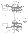
- Fig. 1 illustrates a main rotor shaft support and drive arrangement 10 suited for use in an integrated helicopter transmission wherein the engine and transmission of the helicopter are modularly assembled together into a single unit rigidly mounted to the helicopter frame, as disclosed in U.S. patent application Ser. No. 09/409,991 filed 30 September 1999.
- the support and drive arrangement 10 generally comprises a top thrust ball bearing 11, a spherical roller thrust bearing 12 and a bottom roller bearing 14 cooperating to rotatably support a helicopter rotor 16 extending upwardly through a stationary housing assembly 18 rigidly mounted to the helicopter frame (not shown).
- the top thrust ball bearing 11 is press fitted about the rotor 16.
- Bellows 20 are attached at opposed ends thereof to the bearing 11 and a cover 22 fitted on the top of the housing assembly 18 about the rotor 16.
- the bellows 20 and the cover 22 are welded together and carry a carbon face seal element.
- the bellows 20 and the cover 22 can be bolted to the housing assembly 18.
- a spiral retaining ring 24 is mounted to the rotor 16 above the cover 22 to act as a slinger.
- the spherical roller thrust bearing 12 is preloaded by the top thrust ball bearing 11 and a set of belleville disc springs 26.
- the spherical roller thrust bearing 12 includes an inner race 28 mounted to the rotor 16 for movement therewith, an outer race 30 for engagement with a complementary abutment structure 29 secured to the housing assembly 18, and a number of spherical rollers 32 placed between the inner and outer races 28 and 30.
- the outer race 30 and the abutment structure 29 cooperate to prevent axial removal of the rotor 16 while the helicopter is being operated.
- a fluid bearing damper 34 is provided about the bottom roller bearing 14 to accommodate and absorb vibrations due to rotor dynamics.
- the fluid bearing damper 34 comprises a flexible support 36 secured to the housing 18 and having an axial cylindrical wall 38 for supporting the roller bearing 14.
- the flexible support 36 has a predetermined stiffness to maintain bearing concentricity while allowing the bearing 14, together with the rotor 16, to move in a radial direction around a central axis A of the rotor 16 in an orbital motion.
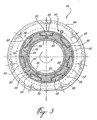
- the cylindrical wall 38 of the flexible support 36 is fitted within a stationary cylinder ring 40 containing a number of interconnected oil cylinders 42.
- the ring 40 acts as a snubber limiting the flexible support 36 deflection.
- the ring 40 is, in turn, tightly fitted and supported within a cylindrical support 44 secured to the stationary housing 18.
- each oil cylinder 42 includes a chamber 46 defined in an outer annular surface 48 of the ring 40 and a piston 50 slidably mounted within the chamber 46 for movement in a radial direction relative to the central axis A of the rotor 16.
- the chambers 46 have respective first and second opposed ends 52 and 54.
- the first end 52 of each chamber 46 is closed by an inner cylindrical surface 56 of the support 44.
- Each piston 50 includes a piston rod 58 extending outwardly of the associated chamber 46 through the second end 54 thereof.
- the piston rods 58 extend radially inwardly of the ring 40 for engagement with an outer cylindrical surface 60 of the flexible support 36, thereby allowing each piston 50 to be pushed by the flexible support 36 against the damping fluid, i.e. the oil, to oppose a radial movement of the bearing 14 and the rotor 16.
- Fluid passages 62 are provided between the chambers to connect the oil cylinders 42 in fluid flow communication.
- Each passage 62 is formed by the inner cylindrical surface 56 of the support 44 and a groove 64 defined in the outer surface 48 of the ring 40.
- the interconnecting passages 62 not necessarily have to be of the same size. However, the passages 62 all have a fluid inlet 66 and a fluid outlet 68.
- the fluid outlets 68 are provided at the first ends 52 of the chambers 46, whereas the fluid inlets 66 are located at a distance from these first ends 52 so as to be blocked by the pistons 50 when the same are pushed into the chambers 46 under bearing loads.
- This arrangement of the fluid passages 62 will ensure that the oil will mainly flow successively through each chamber 46 in a predetermined direction starting from one of the chambers 46 into which the associated piston 50 is pushed. Furthermore, by positioning the fluid inlets 66 on the side of the chambers 46 which corresponds to the rotating direction of the rotor 16, the flow of oil will be in the same direction as that of the shaft rotation.
- the oil flow is regulated by a number of feed holes 70 defined in the support 44 and communicating with the passages 62. Oil bleeding occurs through the gap between the pistons 50 and the chambers 46.
- the fluid bearing damper 34 operates similarly to conventional squeeze-film damper wherein an oil film is squeezed (sheared) under the action of bearing loads and whirling of the rotor, resulting in energy absorption.
- the oil film is substituted by the cylinders 42 where squeezing oil creates much more resistance matching much higher loads and vibratory energy.
- a bevel gear 76 forming part of a drive assembly 72 is in meshing engagement with a reduction bevel gear 80 for transmitting the mechanical power generated by the helicopter engine (not shown) to the rotor 16.
- the bevel gear 76 is journaled by suitable bearings 78 relative to the housing assembly 18.
- the reduction bevel gear 80 is provided with a central tubular portion 74 mounted about the rotor 16 via anti-friction bearings 82 and 84 respectively mounted to the housing assembly 18 and the support 44 via suitable means.
- a sun gear structure 86 is disposed about the rotor 16 and is coupled at a lower end portion thereof to an inner surface of the central tubular portion 74 of the bevel gear 80 by a free spline.
- the sun gear structure 86 is meshed with a planet gear 88 which is also meshed with a fixed internal ring gear 90 concentrically disposed about the sun gear 86 and secured to the housing 18, such as at 92.
- the planet gear 88 is carried by a planet carrier 94 which is operatively connected to the rotor 16 via a flexible free spline coupling 96 designed to obtain highest misalignment capability.
- the flexible free spline coupling 96 is provided in the form of two axially spaced-apart disc members 98 and 100 fitted about the rotor 16 and connected to each other via a cylindrical web 102 provided at an inner diameter of the disc members 98 and 100 to form a diaphragm structure having a low bending stiffness so as to allow the disc members 98 and 100 to flex relative to one another to compensate for the tilting of the rotor 16 during use.
- the disc members 98 and 100 are respectively provided at the periphery thereof with first and second series of circumferentially distributed teeth 104 and 106.
- the first and second series of teeth 104 and 106 respectively form first and second splines.
- the first series of teeth 104 is in meshing engagement with a corresponding series of circumferentially distributed teeth 108 provided on an inner annular surface of the planet carrier 94.
- the second series of teeth 106 is in meshing engagement with a corresponding series of circumferentially distributed teeth 110 provided on an inner annular surface of a disc member 112 connected to the rotor 16.
- the flexible free spline coupling 96 is freely fitted about the rotor 16 between the planet carrier 94 and the disc member 112 to transmit a torque therebetween, while allowing limited relative angular movement between the planet carrier 94 and the disc member 112, and, thus the rotor 16.
- the disc member 112 is provided with an internal series of circumferentially distributed teeth 114 for meshing engagement with a corresponding axially extending teeth 116 provided on the rotor 16, thereby allowing a torque to be transferred from the disc member 112 to the rotor 16. It is understood that the disc 112 could be attached to the rotor 16 by a fixed spline or otherwise.
- the outer race 30 of the spherical roller bearing 12 is placed on an imaginary sphere having a center corresponding to the intersection of the central axis A of the helicopter rotor and a symmetric plane P of the free spline coupling 96 where the radial deflection of the rotor 16 and thereby the radial offset of the free spline coupling 96 are minimal.
Landscapes
- Engineering & Computer Science (AREA)
- General Engineering & Computer Science (AREA)
- Mechanical Engineering (AREA)
- Aviation & Aerospace Engineering (AREA)
- Support Of The Bearing (AREA)
- Vibration Prevention Devices (AREA)
- Fluid-Damping Devices (AREA)
- Retarders (AREA)
- Gear Transmission (AREA)
- Hydraulic Motors (AREA)
- Turbine Rotor Nozzle Sealing (AREA)
Abstract
Description
Claims (16)
- A helicopter rotor support and drive arrangement, comprising:a stationary housing (18) adapted to be rigidly mounted to an airframe of a helicopter;a helicopter rotor (16) extending through said stationary housing (18);bearings (11,12,14) for rotatably supporting said helicopter rotor (16) in said stationary housing (18);a fluid damping structure (34) for accommodating radial motion of said helicopter rotor (16) relative to said stationary housing (18);a driving member (94) mounted in said stationary housing and having a first meshing structure;a driven member (112) for rotation with said helicopter rotor (16) and having a second meshing structure; andan intermediate diaphragm coupling (96) mounted about said helicopter rotor (16) and having third and fourth axially spaced-apart meshing structures flexibly connected to each other for meshing engagement, respectively, with said first and second meshing structures to transmit a torque from said driving member (94) to said driven member (112) and said helicopter rotor (16).
- An arrangement as defined in claim 1, wherein said third and fourth meshing structures include third (104) and fourth (106) series of teeth that are respectively circumferentially distributed at the periphery of a pair of axially spaced-apart disc-shaped members (98,100) connected at an inner diameter thereof by a web (102) for allowing said disc-shaped members (98,100) to flex relative to each other to compensate for misalignment of the rotor shaft (16).
- An arrangement as defined in claims 1 or 2, wherein said diaphragm coupling (96) is adapted to be freely fitted about the rotor shaft (16) between the driving (94) and driven (112) members.
- An arrangement as defined in any preceding claim, wherein said first meshing structure includes a first series of teeth (108) circumferentially distributed on an inner diameter of said driving member (94), and wherein said second meshing structure includes a second series of teeth (110) circumferentially distributed on a first inner diameter of said driven member (112).
- An arrangement as defined in claim 14, wherein said driven member has a second inner diameter concentrically disposed within said first inner diameter thereof, and wherein a fifth series of circumferentially distributed teeth (114) are provided on said second inner diameter for meshing engagement with corresponding teeth (116) on said helicopter rotor (16).
- An arrangement as defined in any preceding claim, wherein said bearings include top (11,12) and bottom (14) bearings, and wherein said fluid damping structure (34) is positioned about said bottom bearing (14).
- An arrangement as defined in claim 6, wherein said fluid damping structure (34) comprises a series of circumferentially distributed fluid cylinders (42) concentrically placed about said bottom bearing (14), each said fluid cylinder (42) being radially oriented relative to said bottom bearing (14) and defining a chamber (46) in which a piston (50) is slidably displaceable against a damping fluid to oppose a radial movement of the bottom bearing (14).
- An arrangement as defined in claim 7, wherein said chambers (46) are connected in fluid flow communication.
- An arrangement as defined in claim 8, wherein said chambers (46) are serially interconnected in a loop configuration through fluid passages (62) extending between the chambers (46), the fluid passages (62) being arranged so that the damping fluid flows successively through each chamber (46) in a predetermined direction starting from one of the chambers (46) into which the associated piston (50) is pushed.
- An arrangement as defined in claim 9, wherein said fluid passages (62) have respective fluid inlets (66) and fluid outlets (68), said fluid inlets (66) being positioned so as to be blocked by said pistons (50) when pushed into said chambers (46) to a predetermined depth of insertion.
- An arrangement as defined in claim 10, wherein each piston (50) has a piston rod (58) extending outwardly from a first end of a corresponding one of said chambers (46) opposite a second end thereof, and wherein said fluid outlets (68) are located at the level of said second ends of said chambers (46).
- An arrangement as defined in any of claims 7 to 11, wherein said chambers (46) are defined in a stationary ring member (40), and wherein each said piston (50) includes a piston rod (58) extending radially inwardly of said stationary ring member (40) so as to be individually actuable in response to a radial motion of the bottom bearing (14).
- An arrangement as defined in claim 12, wherein said stationary ring member (40) is fitted within a cylindrical support (44) rigidly supported in said stationary housing (18) and having an inner surface tightly encircling an outer surface of said stationary ring member (40) for closing each of said chambers (46).
- An arrangement as defined in any of claims 7 to 11, wherein said cylinders (42) are provided on a ring (40), and wherein each said piston (50) includes a piston rod (58) extending radially inwardly of said ring (40) for allowing said cylinders (42) to be individually actuated by said bottom bearing in response to a radial motion thereof.
- An arrangement as defined in any of claims 7 to 14, further including a support (36) secured to said stationary housing (18) for supporting said bottom bearing (14) concentrically within said series of circumferentially distributed fluid cylinders (42), while allowing restrained radial motion of said bottom bearing (14) with said helicopter rotor (16).
- An arrangement as defined in any of claims 7 to 15, wherein said top bearing includes a spherical roller thrust bearing (12) having a number of rollers comprised between inner (28) and outer (30) races, said outer race (30) being placed on an imaginary sphere having a center corresponding to the intersection of a central axis (A) of the helicopter rotor (16) and a symmetric plane (P) of said diaphragm coupling (96).
Applications Claiming Priority (3)
| Application Number | Priority Date | Filing Date | Title |
|---|---|---|---|
| US09/742,010 US6394387B1 (en) | 2000-12-22 | 2000-12-22 | Rotor shaft support and drive arrangement |
| US742010 | 2000-12-22 | ||
| EP01271926A EP1343979B1 (en) | 2000-12-22 | 2001-12-18 | Rotor shaft support |
Related Parent Applications (2)
| Application Number | Title | Priority Date | Filing Date |
|---|---|---|---|
| EP01271926A Division EP1343979B1 (en) | 2000-12-22 | 2001-12-18 | Rotor shaft support |
| EP01271926.6 Division | 2001-12-18 |
Publications (2)
| Publication Number | Publication Date |
|---|---|
| EP1598268A1 true EP1598268A1 (en) | 2005-11-23 |
| EP1598268B1 EP1598268B1 (en) | 2008-08-20 |
Family
ID=24983144
Family Applications (2)
| Application Number | Title | Priority Date | Filing Date |
|---|---|---|---|
| EP05016185A Expired - Lifetime EP1598268B1 (en) | 2000-12-22 | 2001-12-18 | Rotor shaft support and drive arrangement |
| EP01271926A Expired - Lifetime EP1343979B1 (en) | 2000-12-22 | 2001-12-18 | Rotor shaft support |
Family Applications After (1)
| Application Number | Title | Priority Date | Filing Date |
|---|---|---|---|
| EP01271926A Expired - Lifetime EP1343979B1 (en) | 2000-12-22 | 2001-12-18 | Rotor shaft support |
Country Status (6)
| Country | Link |
|---|---|
| US (1) | US6394387B1 (en) |
| EP (2) | EP1598268B1 (en) |
| JP (2) | JP3866658B2 (en) |
| CA (1) | CA2436344C (en) |
| DE (2) | DE60120755T2 (en) |
| WO (1) | WO2002052165A2 (en) |
Cited By (2)
| Publication number | Priority date | Publication date | Assignee | Title |
|---|---|---|---|---|
| WO2009062378A1 (en) * | 2007-10-17 | 2009-05-22 | Mingzheng Shi | A circular transmission case and a controlling mechanism |
| CN100585223C (en) * | 2006-03-15 | 2010-01-27 | 石铭正 | Cylinder-shaped speed-changing box |
Families Citing this family (27)
| Publication number | Priority date | Publication date | Assignee | Title |
|---|---|---|---|---|
| US6513753B1 (en) * | 2001-08-14 | 2003-02-04 | Sikorsky Aircraft Corporation | Transmission support structure for a rotary wing aircraft |
| US7104918B2 (en) | 2003-07-29 | 2006-09-12 | Pratt & Whitney Canada Corp. | Compact epicyclic gear carrier |
| RU2263608C1 (en) * | 2004-04-01 | 2005-11-10 | Открытое акционерное общество "Камов" | Light helicopter gearbox |
| US8602166B2 (en) * | 2006-01-05 | 2013-12-10 | Sikorsky Aircraft Corporation | Secondary lubrication system with injectable additive |
| US8585538B2 (en) * | 2006-07-05 | 2013-11-19 | United Technologies Corporation | Coupling system for a star gear train in a gas turbine engine |
| US8459413B2 (en) * | 2007-01-19 | 2013-06-11 | Sirkorsky Aircraft Corporation | Lubrication system with prolonged loss of lubricant operation |
| GB2446863A (en) | 2007-02-21 | 2008-08-27 | Smiths Aerospace Ltd | Diaphragm coupling with stops to limit range of movement |
| RU2402457C1 (en) * | 2009-05-12 | 2010-10-27 | Надим Зейнидинович Гашумов | Swashplate |
| US8672801B2 (en) * | 2009-11-30 | 2014-03-18 | United Technologies Corporation | Mounting system for a planetary gear train in a gas turbine engine |
| US8439567B1 (en) | 2010-11-10 | 2013-05-14 | Curtiss-Wright Electro-Mechanical Corporation | Disc springs/carrier plate preload assembly |
| DE102011009071A1 (en) * | 2011-01-20 | 2012-07-26 | Schottel Gmbh | Rudderpropeller |
| US8992161B2 (en) | 2011-08-26 | 2015-03-31 | Honeywell International Inc. | Gas turbine engines including broadband damping systems and methods for producing the same |
| US9046001B2 (en) * | 2011-08-29 | 2015-06-02 | Honeywell International Inc. | Annular bearing support dampers, gas turbine engines including the same, and methods for the manufacture thereof |
| US10119476B2 (en) | 2011-09-16 | 2018-11-06 | United Technologies Corporation | Thrust bearing system with inverted non-contacting dynamic seals for gas turbine engine |
| US9297438B2 (en) | 2012-01-25 | 2016-03-29 | Honeywell International Inc. | Three parameter damper anisotropic vibration isolation mounting assembly |
| DE102012203178B4 (en) * | 2012-03-01 | 2020-03-12 | Zf Friedrichshafen Ag | Power transmission device of a rotary wing aircraft |
| US9121448B2 (en) * | 2013-10-11 | 2015-09-01 | General Electric Company | Hermetically sealed damper assembly and methods of assembling same |
| WO2016025491A1 (en) * | 2014-08-13 | 2016-02-18 | Sikorsky Aircraft Corporation | Viscous damper |
| GB201516571D0 (en) * | 2015-09-18 | 2015-11-04 | Rolls Royce Plc | A Coupling for a Geared Turbo Fan |
| US9702404B2 (en) | 2015-10-28 | 2017-07-11 | United Technologies Corporation | Integral centering spring and bearing support and method of supporting multiple damped bearings |
| FR3055883B1 (en) | 2016-09-09 | 2019-03-29 | Airbus Helicopters | MECHANICAL SYSTEM FOR TRANSMITTING A MOVEMENT AND AIRCRAFT EQUIPPED WITH A CORRESPONDING SYSTEM |
| CA3004054C (en) | 2017-05-05 | 2024-02-13 | Laflamme Aero Inc. | Helicopter rotor hub assembly and helicopter including same |
| CN107178519B (en) * | 2017-07-03 | 2019-07-30 | 沈阳鼓风机集团安装检修配件有限公司 | A kind of incline encapsulating method and device inhibiting centrifugal compressor flow-induced vibration |
| US10662879B2 (en) | 2017-08-08 | 2020-05-26 | Pratt & Whitney Canada Corp. | Epicyclic gear stage |
| US10927944B2 (en) | 2018-01-26 | 2021-02-23 | Pratt & Whitney Canada Corp. | Compact, twist controlled planet carrier and epicyclic gear train having same |
| US10760677B2 (en) | 2018-01-31 | 2020-09-01 | Pratt & Whitney Canada Corp. | Epicyclic gear train with balanced carrier stiffness |
| EP4056469B1 (en) * | 2021-03-11 | 2023-05-24 | Leonardo S.p.A. | Aircraft capable of hovering |
Citations (5)
| Publication number | Priority date | Publication date | Assignee | Title |
|---|---|---|---|---|
| US2434276A (en) * | 1943-01-06 | 1948-01-13 | Isidor B Laskowitz | Tiltable counter-rotating rotor system for helicopters and control means therefor |
| GB885652A (en) * | 1957-11-27 | 1961-12-28 | Arthur Middleton Young | Improvements in or relating to a convertible aircraft |
| US3087690A (en) * | 1961-01-30 | 1963-04-30 | Doman Helicopters Inc | Rotor with two joints in drive shaft |
| US4695340A (en) * | 1985-09-30 | 1987-09-22 | United Technologies Corporation | Filament wound structure having filament wound reinforcing rings for use as a torque drive |
| US4877375A (en) * | 1986-09-30 | 1989-10-31 | The Boeing Company | Drive shaft and rotor hub for helicopter flexible rotor system |
Family Cites Families (23)
| Publication number | Priority date | Publication date | Assignee | Title |
|---|---|---|---|---|
| US3497164A (en) * | 1968-03-15 | 1970-02-24 | Hobbs H Horak | Vibration isolator |
| SE345072B (en) * | 1969-10-09 | 1972-05-15 | Skf Svenska Kullagerfab Ab | |
| DE2104612A1 (en) * | 1970-02-02 | 1971-08-12 | Commissariat Energie Atomique | Guidance for the automatic alignment of a component to be guided |
| DE2557875C2 (en) * | 1975-12-22 | 1985-05-30 | Sulzer-Escher Wyss GmbH, 7980 Ravensburg | Radial bearing for a large diameter rotor |
| US4544285A (en) * | 1983-04-18 | 1985-10-01 | The United States Of America As Represented By The Secretary Of The Navy | Fluid equalized tilting pad thrust bearings |
| JPS63135612A (en) * | 1986-11-26 | 1988-06-08 | Hitachi Ltd | damping bearing |
| DE3708596A1 (en) | 1987-03-17 | 1988-09-29 | Mtu Muenchen Gmbh | GAS TURBINE SYSTEM FOR HELICOPTERS |
| JPH0735809B2 (en) * | 1987-07-03 | 1995-04-19 | 株式会社日立製作所 | Oil pump shaft support device |
| US4947639A (en) * | 1988-05-12 | 1990-08-14 | United Technologies Corporation | Apparatus and method for supporting a rotating shaft in a rotary machine |
| JPH03244825A (en) * | 1990-02-20 | 1991-10-31 | Nippon Seiko Kk | Bearing device |
| GB9006668D0 (en) * | 1990-03-24 | 1990-05-23 | Westland Helicopters | Rotors |
| US5088840A (en) * | 1990-07-26 | 1992-02-18 | United Technologies Corporation | Dashpot damper |
| US5044781A (en) * | 1990-07-26 | 1991-09-03 | United Technologies Corporation | Spring supported damping system |
| FR2683204B1 (en) * | 1991-10-30 | 1997-04-25 | Aerospatiale | SYSTEM FOR BACKING UP A MULTIPLIER / REDUCER MECHANICAL ASSEMBLY, PARTICULARLY OF THE HELICOPTER "TRANSMISSION" TYPE, IN CASE OF LOSS OF LUBRICATING OIL. |
| JPH05164127A (en) * | 1991-12-13 | 1993-06-29 | Hitachi Seiko Ltd | Bearing preload device |
| US5344239A (en) | 1992-11-25 | 1994-09-06 | General Electric Company | Squeeze film bearing damper with annular end plenums |
| US5755622A (en) * | 1993-04-26 | 1998-05-26 | Mitsubish Jukogyo Kabushiki Kaisha | Centrifugally operated axial and torsional vibration reducer for a diaphragm coupling |
| FR2725420B1 (en) * | 1994-10-11 | 1996-12-13 | Eurocopter France | PITCH CONTROL DEVICE FOR ROTOR WITHOUT ARTICULATION |
| US5452957A (en) * | 1994-11-22 | 1995-09-26 | Dana Corporation | Center bearing assembly including support member containing rheological fluid |
| US5716300A (en) * | 1996-05-01 | 1998-02-10 | Sikorsky Aircraft Corporation | Isolated ring gear for planetary gear drive systems |
| FI117486B (en) * | 1997-02-14 | 2006-10-31 | Metso Paper Inc | Roller for a paper machine or paper finishing machine |
| EP0892893A1 (en) * | 1997-02-14 | 1999-01-27 | Valmet Corporation | Bearing control system for a roll with hydrostatic bearings |
| US5738445A (en) * | 1997-02-21 | 1998-04-14 | Delaware Capital Formation, Inc. | Journal bearing having vibration damping elements |
-
2000
- 2000-12-22 US US09/742,010 patent/US6394387B1/en not_active Expired - Lifetime
-
2001
- 2001-12-18 DE DE60120755T patent/DE60120755T2/en not_active Expired - Lifetime
- 2001-12-18 EP EP05016185A patent/EP1598268B1/en not_active Expired - Lifetime
- 2001-12-18 CA CA2436344A patent/CA2436344C/en not_active Expired - Fee Related
- 2001-12-18 DE DE60135508T patent/DE60135508D1/en not_active Expired - Lifetime
- 2001-12-18 EP EP01271926A patent/EP1343979B1/en not_active Expired - Lifetime
- 2001-12-18 JP JP2002553027A patent/JP3866658B2/en not_active Expired - Fee Related
- 2001-12-18 WO PCT/CA2001/001812 patent/WO2002052165A2/en not_active Ceased
-
2006
- 2006-07-24 JP JP2006200178A patent/JP2006300339A/en active Pending
Patent Citations (5)
| Publication number | Priority date | Publication date | Assignee | Title |
|---|---|---|---|---|
| US2434276A (en) * | 1943-01-06 | 1948-01-13 | Isidor B Laskowitz | Tiltable counter-rotating rotor system for helicopters and control means therefor |
| GB885652A (en) * | 1957-11-27 | 1961-12-28 | Arthur Middleton Young | Improvements in or relating to a convertible aircraft |
| US3087690A (en) * | 1961-01-30 | 1963-04-30 | Doman Helicopters Inc | Rotor with two joints in drive shaft |
| US4695340A (en) * | 1985-09-30 | 1987-09-22 | United Technologies Corporation | Filament wound structure having filament wound reinforcing rings for use as a torque drive |
| US4877375A (en) * | 1986-09-30 | 1989-10-31 | The Boeing Company | Drive shaft and rotor hub for helicopter flexible rotor system |
Cited By (2)
| Publication number | Priority date | Publication date | Assignee | Title |
|---|---|---|---|---|
| CN100585223C (en) * | 2006-03-15 | 2010-01-27 | 石铭正 | Cylinder-shaped speed-changing box |
| WO2009062378A1 (en) * | 2007-10-17 | 2009-05-22 | Mingzheng Shi | A circular transmission case and a controlling mechanism |
Also Published As
| Publication number | Publication date |
|---|---|
| EP1598268B1 (en) | 2008-08-20 |
| EP1343979A2 (en) | 2003-09-17 |
| DE60135508D1 (en) | 2008-10-02 |
| JP2004523699A (en) | 2004-08-05 |
| DE60120755D1 (en) | 2006-07-27 |
| CA2436344A1 (en) | 2002-07-04 |
| CA2436344C (en) | 2011-05-03 |
| WO2002052165A2 (en) | 2002-07-04 |
| JP2006300339A (en) | 2006-11-02 |
| US6394387B1 (en) | 2002-05-28 |
| WO2002052165A3 (en) | 2003-01-03 |
| JP3866658B2 (en) | 2007-01-10 |
| DE60120755T2 (en) | 2007-05-31 |
| EP1343979B1 (en) | 2006-06-14 |
Similar Documents
| Publication | Publication Date | Title |
|---|---|---|
| US6394387B1 (en) | Rotor shaft support and drive arrangement | |
| KR960702075A (en) | Power train with vibration dampening mechanism | |
| US4981415A (en) | Support for oil film dampers | |
| US20050082136A1 (en) | Hydraulic double clutch | |
| US12018725B2 (en) | Shaft couplings | |
| US6715595B2 (en) | Torsional vibration damper | |
| JP2001280233A (en) | Hub drive | |
| JP2009103312A (en) | Improvement in continuously variable ratio power transmission device | |
| EP1210532B1 (en) | Gearing for power sharing in planetary transmission | |
| CA1096656A (en) | Vibratory mechanism | |
| US7021443B2 (en) | Clutch system | |
| CN116292655B (en) | A temperature control component | |
| US2968286A (en) | Hydraulic axial-piston machine | |
| CN103225677A (en) | Variator assembly | |
| GB2028969A (en) | Shaft assembly | |
| EP4117823B1 (en) | A bearing member for supporting a rotatable axle | |
| KR102815359B1 (en) | Constant velocity joint | |
| GB2178824A (en) | Divided flywheel with an interchangeable torsion damping device | |
| US20220373038A1 (en) | Coupling | |
| US3439562A (en) | Speed-change mechanism | |
| EP0493388A4 (en) | Universal joint having hemispherical cup-shaped yoke and exterior, lubricating ring | |
| US4398843A (en) | Self-aligning arrangement for the eccentric mounting shaft of a vibratory compactor | |
| WO2014098353A1 (en) | Torque converter for vehicle | |
| CA1088882A (en) | Variable speed drive | |
| CN202301495U (en) | Rear power takeoff transmission component of diesel engine |
Legal Events
| Date | Code | Title | Description |
|---|---|---|---|
| PUAI | Public reference made under article 153(3) epc to a published international application that has entered the european phase |
Free format text: ORIGINAL CODE: 0009012 |
|
| AC | Divisional application: reference to earlier application |
Ref document number: 1343979 Country of ref document: EP Kind code of ref document: P |
|
| AK | Designated contracting states |
Kind code of ref document: A1 Designated state(s): DE FR GB |
|
| 17P | Request for examination filed |
Effective date: 20060522 |
|
| 17Q | First examination report despatched |
Effective date: 20060621 |
|
| AKX | Designation fees paid |
Designated state(s): DE FR GB |
|
| GRAP | Despatch of communication of intention to grant a patent |
Free format text: ORIGINAL CODE: EPIDOSNIGR1 |
|
| GRAS | Grant fee paid |
Free format text: ORIGINAL CODE: EPIDOSNIGR3 |
|
| GRAA | (expected) grant |
Free format text: ORIGINAL CODE: 0009210 |
|
| AC | Divisional application: reference to earlier application |
Ref document number: 1343979 Country of ref document: EP Kind code of ref document: P |
|
| AK | Designated contracting states |
Kind code of ref document: B1 Designated state(s): DE FR GB |
|
| REG | Reference to a national code |
Ref country code: GB Ref legal event code: FG4D |
|
| REF | Corresponds to: |
Ref document number: 60135508 Country of ref document: DE Date of ref document: 20081002 Kind code of ref document: P |
|
| PLBE | No opposition filed within time limit |
Free format text: ORIGINAL CODE: 0009261 |
|
| STAA | Information on the status of an ep patent application or granted ep patent |
Free format text: STATUS: NO OPPOSITION FILED WITHIN TIME LIMIT |
|
| 26N | No opposition filed |
Effective date: 20090525 |
|
| PGFP | Annual fee paid to national office [announced via postgrant information from national office to epo] |
Ref country code: DE Payment date: 20131211 Year of fee payment: 13 |
|
| REG | Reference to a national code |
Ref country code: DE Ref legal event code: R119 Ref document number: 60135508 Country of ref document: DE |
|
| PG25 | Lapsed in a contracting state [announced via postgrant information from national office to epo] |
Ref country code: DE Free format text: LAPSE BECAUSE OF NON-PAYMENT OF DUE FEES Effective date: 20150701 |
|
| REG | Reference to a national code |
Ref country code: FR Ref legal event code: PLFP Year of fee payment: 15 |
|
| REG | Reference to a national code |
Ref country code: FR Ref legal event code: PLFP Year of fee payment: 16 |
|
| REG | Reference to a national code |
Ref country code: FR Ref legal event code: PLFP Year of fee payment: 17 |
|
| PGFP | Annual fee paid to national office [announced via postgrant information from national office to epo] |
Ref country code: FR Payment date: 20181127 Year of fee payment: 18 Ref country code: GB Payment date: 20181127 Year of fee payment: 18 |
|
| GBPC | Gb: european patent ceased through non-payment of renewal fee |
Effective date: 20191218 |
|
| PG25 | Lapsed in a contracting state [announced via postgrant information from national office to epo] |
Ref country code: GB Free format text: LAPSE BECAUSE OF NON-PAYMENT OF DUE FEES Effective date: 20191218 Ref country code: FR Free format text: LAPSE BECAUSE OF NON-PAYMENT OF DUE FEES Effective date: 20191231 |