EP1598267A2 - Directional control system and method for marine vessels - Google Patents
Directional control system and method for marine vessels Download PDFInfo
- Publication number
- EP1598267A2 EP1598267A2 EP05103712A EP05103712A EP1598267A2 EP 1598267 A2 EP1598267 A2 EP 1598267A2 EP 05103712 A EP05103712 A EP 05103712A EP 05103712 A EP05103712 A EP 05103712A EP 1598267 A2 EP1598267 A2 EP 1598267A2
- Authority
- EP
- European Patent Office
- Prior art keywords
- steering mechanism
- control element
- control
- movement
- directional
- Prior art date
- Legal status (The legal status is an assumption and is not a legal conclusion. Google has not performed a legal analysis and makes no representation as to the accuracy of the status listed.)
- Granted
Links
Images


Classifications
-
- B—PERFORMING OPERATIONS; TRANSPORTING
- B63—SHIPS OR OTHER WATERBORNE VESSELS; RELATED EQUIPMENT
- B63H—MARINE PROPULSION OR STEERING
- B63H25/00—Steering; Slowing-down otherwise than by use of propulsive elements; Dynamic anchoring, i.e. positioning vessels by means of main or auxiliary propulsive elements
- B63H25/02—Initiating means for steering, for slowing down, otherwise than by use of propulsive elements, or for dynamic anchoring
Definitions
- the present invention relates to a directional control system for marine vessels, such as ships or the like, comprising, at least a steering mechanism dipped or that can be dipped and that can rotate about an axis contained in a plane parallel to the longitudinal axis of the ship or coinciding with said axis, which steering mechanism can be moved between two opposite extreme positions each being corresponded or correlated with a maximum directional steering angle in one of two opposite directional steering directions of the marine vessel with respect to a straight travelling direction; means for actuating the movement of said at least one steering mechanism between said two extreme positions; at least a directional control station of the marine vessel wherein at least a control element is provided for setting the directional steering, which control element can be moved between two opposite extreme stop positions; means for transmitting the movement stroke of the control element or the position of the control element with respect to the total stroke to means actuating the movement of said at least one steering mechanism, which transmitting means transform the control element stroke in signals for actuating actuators moving the at least one dipped steering mechanism according
- the steering mechanism may be composed at least of a rudder blade.
- Each rudder blade is mounted on a shaft that is rotatable in the vertical plane oriented parallel to the longitudinal axis or coinciding with the longitudinal axis of the ship.
- the steering mechanism may be composed of the so called sterndrive of an outboard motor or in-outboard motor, which sterndrive bears a propeller and it is mounted in a rotatable way as the blade.
- connection of the steering wheel or the rudder wheel or the rudder tiller to a rudder balde or a sterndrive of an outboard or in-outboard motor takes place by means of mechanical means, such as an arrangement of cables transmitting the rotational motion of the steering wheel or rudder wheel or the angular movement of the rudder tiller to the motor sterndrive or blade.
- mechanical means such as an arrangement of cables transmitting the rotational motion of the steering wheel or rudder wheel or the angular movement of the rudder tiller to the motor sterndrive or blade.
- the so called servo-driven systems are also known wherein the mechanical transmission occurs by means of hydraulic or oil-pressure transmission systems.
- a pump is mechanically connected to the control element and in turn it is part of a closed hydraulic circuit comprising a double-acting actuating cylinder or in case also an hydraulic motor.
- the change in pressure in the two branches of the hydraulic circuit caused by the movement of the control member by a manual steering or by a change in direction on the steering wheel, on the rudder wheel or rudder tiller causes the actuating cylinder to be actuated in one or the other direction or the hydraulic motor to be rotate in one or the other direction and so it causes the angular movement of the rudder blade or sterndrive of outboard or in-outboard motor.
- a first drawback is the fact that both in mechanical version and hydraulic version the system assembling requires the passage of pull and push cables or hydraulic piping running through the ship or through part thereof. Therefore special housings must be provided for cables or hydraulic piping and said housings must be easy to access to for control and replacement. Moreover housings must be big enough to allow the free sliding of cables in their sheaths or the passage of pressure fluid piping of the hydraulic system, as well as their assembling or replacement.
- the function correlating the position of the steering control element and the corresponding position of the dipped steering mechanism for example the angular position of the steering wheel with respect to the total stroke thereof and the angular position of a rudder blade or sterndrive of an outboard motor, being integrated in the physical structure of the mechanical system (cables and tie rods) or hydraulic system (connections of fluid piping and possible distribution) the adjustment of the system both in first operation step and in a following adjustment step may be carried out only by mechanical or hydraulic adjustment means depending on the system type.
- Adjustments must be frequently carried out since both just mechanical systems and just hydraulic systems are submitted to a degradetion of operating conditions, such as for example an increase of slacks, a decrease in the amount of fluid or other wear effects.
- a drawback is the fact of having functions correlating the position of the control element and the position of the steering mechanism integrated in a stable way since it prevents said function from being changed or modified. Moreover diagnostic and emergency systems and functionalities can hardly be executed or integrated.
- a further drawback is the fact that known steerage systems can not be absolutely integrated in an electronic function control system such the already existing one for accelerating control or reversing control, while electronic means used for said accelerating or reversing controls can be used also in steerage controls.
- the invention aims to provide a directional control system for marine vessels, such as ships or the like, of the type disclosed above overcoming drawbacks of known systems.
- the invention achieves the above aims with a system of the type disclosed above and wherein it is further provided that means for transmitting the movement stroke of the control element or the position of the control element with respect to the total stroke to means actuating the movement of at least said one steering mechanism are electric type means.
- a electromechanical transducer generating an electrical signal univocally correlated to the stroke made by the control element or to the position taken by the control element with respect to its total stroke.
- control elements are of the type that can rotate about an axis or can be angularly moved, such as a steering wheel, a rudder wheel or a rudder tiller, then it is possibile to use for example potentiometers as transducers, whose slider is mechanically coupled to the shaft of rotation or angular movement of the control element, for example potentiometers having rotating slider, the spindle of the slider being connected directly or by means of a reduction unit to the shaft of the control element.
- potentiometers can be used optical, electromagnetic encoders, or the like detecting the rotation of the spindle of the steering wheel or the like and generating a signal correlated to the angle of rotation.
- an electrical actuator such as a rotatable electrical motor or an electromechanical linear actuator.
- the electrical signal univocally correlated to the stroke or position of the control element is provided as control signal thereof to a power supply unit of the electric motor and/or electromechanical linear actuator.
- the power supply unit in this case actuates the electrical motor or the linear electrical actuator, for an amount of time necessary for making the stroke or for reaching the position of the steering mechanism that are univocally correlated to the stroke or position of the control element respectively transmitted as electrical signal.
- a varying embodiment provides that the electrical actuator such as the electrical motor or the electromechanical linear actuator controls a pump or an hydraulic motor driving an hydraulic actuator, which pump or hydraulic motor and which hydraulic linear actuator are provided in a closed hydraulic circuit driving the steering mechanism.
- said hydraulic system driving the steering mechanism is locally provided in the area of the steering mechanism. Particularly in the area of the shaft of rotation or of angular movement of the steering mechanism.
- a mechanical system driving the steering mechanism instead of the hydraulic system driving the steering mechanism there is provided a mechanical system driving the steering mechanism provided with transmission tie rods or cables, the electrical motor or the electromechanical linear actuator being dinamically connected to said tie rods or cables for driving the steering mechanism.
- the mechanical system driving the steering mechanism may be locally provided near said steering mechanism and when said steering mechanism has a shaft of rotation at said shaft.
- the system according to the invention comprises:
- the stroke of the control element causes the actuator moving the dipped steering mechanism to be actuated according to a function correlating the movement stroke or the position of the control element within the total stroke thereof and the movement stroke or the position of the steering mechanism respectively.
- electromechanical transducer associated to the steering control element and the power supply unit are associated to local intelligent dedicated units or they integrate local intelligent dedicated units.
- the electromechanical transducer and the power supply unit have a control and processing electronic portion comprising a CPU, at least an input portion and at least an output portion composed of communications units working according to a predefined communications protocol.
- Processing portions dedicated to functions to be carried out therefrom may be provided instead of CPU.
- a program memory is associated wherein a working program of the transducer and of the power supply unit is loaded.
- the working program may comprise various routines for executing various tasks.
- the working program comprises also the algorithm computing the function that univocally correlates the position or stroke of the control element and position or stroke of the steering mechanism.
- Such function may be in the form of a computation algorithm executed each time the control element is driven or in the form of a correlation table stored in the memory of the corresponding portion, that is of the electromechanical transducer or the associated unit and/or the power supply unit.
- the working program may comprise among others diagnostic subroutines, subroutines indicating error or mulfunction, adjusting subroutines, subroutines setting the correlation function, activation and disactivation and initializing subroutines.
- the communications protocol may be of any type, for example the known protocol widely used in nautical science called BUS CAN. However it should be understood that the present invention is not limited to said protocol.
- a device for indicating the set position of the steering mechanism that according to the correlation function provided in the working program results from the stroke made by the control element or from its position, so called rudder angle.
- An electromechanical detector for the actual position of the steering mechanism that is the so called actual rudder angle
- the signal generated by said detector is transmitted to the electromechanical transducer or to the associated control and processing eletronic unit having a portion for comparing the nominal rudder angle set by the control element with the angular position actually taken by the steering mechanism, that is the actual rudder angle.
- the detector signal associated to the actuator or to the steering mechanism is processed by a comparison subroutine provided in the working program.
- the signal of the rudder angle detector associated to the actuating cylinder or to the steering mechanism may be also provided to the power supply unit that in turn has a comparing portion similar to that disclosed for the processing and control unit of the control element.
- the construction of said power supply unit provides a CPU for executing a working program, said signal of the rudder angle detector is provided to a comparing subroutine of the working program.
- Said detector of the rudder angle may be also integrated in the actuating cylinder.
- the power supply unit generates a control signal for the eletrical motor driving the pump that controls the actuating cylinder corresponding to a predetermined fixed movement speed of the steering mechanism that is independent of the movement speed of the control element.
- a variant provides said movement speed of the steering mechanism to be variable between a minimum speed and a maximum speed, the steering mechanism being moved at the movement speed of the control element, when such speed is within the range of said minimum and maximum speed.
- a further embodiment of the system according to the present invention provides said system to be provided with two, three or more control stations.
- each control station comprises a control element, with its own electromechanical transducer and with a dedicated local processing and control unit.
- each station has command input means for disabling/enabling the station in order to transfer the control function to a different station of the two, three or more further stations.
- the disabling/enabling command is composed of a code comprising at least two different pulses, preferably at least three different pulses and which code is entered by means of input means provided on the control panel of each station, input means of the code being connected to the processing and control local unit and said codes being transmitted to the processing and control unit of the power supply unit of the actuator driving steering means via communications lines for transmitting command signals of the steering mechanism and by means of a transmitting protocol that can be the same or different than that used for command signals of the steering mechanism and particularly it is the same protocol called BUS CAN.
- Enabling and disabling codes can be stored in a memory of processing and control units associated to the control element and/or the power supply unit.
- the system according to the present invention provides, in combination, an emergency system if the transmission or communication between means driving the steering mechanism and the power supply unit of said driving means and/or the control element do not work.
- the power supply unit can not properly control the motor of the hydraulic pump or any motors directly driving the steering mechanism. Therefore it is provided a switch that can be at least manually actuated that directly commutes power supply inputs of the motor to outputs of an electromechanical power supply unit controlled by means of buttons.
- Said electromechanical power supply unit comprises a remote control switch controlled by two buttons for driving the motor in one direction and in the opposite one.
- the system has the advantages of being easy to assemble and very flexible with respect to adjustment, setting and maintenance, and it is very flexible with respect to the provision of specific tasks that can be integrated by simply loading the control software in memories of local processing and control units.
- the system as suggested according to the present invention allows also to be easily integrated with further board device systems working using a transmission bus of command signals and feedback signals.
- a specific system that can be easily integrated or otherwise put into communication and therefore able to work in cooperation with the directional control system according to the present invention is composed of a system controlling the accelerating condition of motors and the reverser.
- the station or stations for controlling the motor acceleration and for controlling the reverser are provided with control elements such as pivoting levers or the like whose movement along a predetermined path generates a signal univocally correlated to the stroke or position and which signal is transmitted to an actuating unit, for example a power supply unit of actuators driving accelerating mechanisms and/or the reverser.
- control elements such as pivoting levers or the like whose movement along a predetermined path generates a signal univocally correlated to the stroke or position and which signal is transmitted to an actuating unit, for example a power supply unit of actuators driving accelerating mechanisms and/or the reverser.
- the two systems are connected one with respect to the other at the electric control or feedback signals by means of an interfacing portion constituting a communication node and at the same time a local, intelligent unit interpreting electric control and feedback signals of two systems and by means of a control and synchronization program it provides to manage manoeuvrings set by means of the two systems in a not conflictual way.
- Such interfacing portion may provide also units for converting signals in a common communications protocol with further devices such as automatic pilot, radar, sonar, satellite navigations systems and with a weather information source, as well as with the B station for an automatic and synchronized execution of marine vessel steering manoeuvrings.
- the intelligent processing unit associated to transducers is removed due to a different type of electromechanical transducer of the movement of the control element for setting the directional steering.
- the detection of the stroke or position of the control element for setting the directional steering is composed of an opto-electronic transducer.
- control element setting the directional steering is composed of an element rotating about an axis, while the transducer is composed of an angular position sensor the so called encoder working with opto-electronic means.
- said encoder comprises an angular movement optical sensor formed of at least a radiation source oriented towards a radiation detector, between said source and said detector there being provided a shielding means provided with a plurality of through slots alternated with full areas which slots extend along a path coinciding with the position of the detector and of the opposing radiation source.
- the shielding element is formed of a disk rotating with the directional control element and through slots are arranged on a circumference whose radial distance coincides with the radial distance at which the emitter/receiver pair is arranged.
- Through slots are alternated with full areas and the angular distance thereof is such that the detector of the emitter/receiver pair emits a receiving pulse each 2° of rotation.
- the encoder is provided in combination with a pulse counter in the time unit, a timer measuring the time being provided.
- the encoder is provided in combination with means for detecting the movement direction, particularly the rotation direction of the directional control element.
- a particular embodiment of these means in combination with a shielding element provided with a row of through slots having a predetermined distance one with respect to the other provides at least a pair of detectors provided in a position coinciding with said row of through slots, but staggered one with respect to the other by a distance that is greater or lower at a predetermined extent than the distance between two subsequent through slots, such that when a detector is perfectly centred with a through slot, the second detector partially coincides with a different through slot, so that substantially square wave alternate signals generated by the two detectors have a predetermined phase one with respect to the other.
- the distance between the two detectors is such that when a first detector perfectly and completely coincides by its sensitive surface with a first through slot the second detector coincides by its sensitive surface with only half of a second through slot, the remaining part of the sensitive surface of said second detector being coinciding with the not transparent part provided between individual slots of the shielding element.
- square wave signals generated by the two detectors will have a phase difference, while the phase difference will have substantially an absolute value identical for the two movement directions of the directional control element, the signal of the first detector will anticipate the signal of the second detector and vice versa depending on the movement direction of the directional control element.
- signals generated by the encoder and transformed in pulses per unit of time are sent to an interfacing unit constituting of a converter that transforms said signals in a typical format to be read by the central processing unit associated to the power supply unit of means driving steering mechanism or mechanisms.
- the signal converter transforms output signals from the counter and corresponding to the number of pulses per unit of time and from the detected difference of phase generated by the encoder in communications signals according to a known communications protocol called Bus Scan.
- Furhter improvements of the invention are the object of sub-claims.
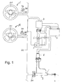
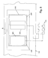
- a directional control system for marine vessels or the like comprises two control stations 1a and 2b each station has a control element 101 in the form of a rotatable mounted steering wheel and an electromechanical transducer is dynamically connected to the shaft of rotation thereof such as a potentiometer or the like (not shown).
- the rotation of the steering wheel causes a movement of the potentiometer slider and therefore the generation of an electrical signal univocally correlated to the position of the steering wheel 101.
- the potentiometer slider may be dynamically connected to the shaft of the steering wheel by means of a reduction unit or a reduction gear adapting the stroke of the steering wheel to the potentiometer slider one.
- the potentiometer is connected to a control and command unit 201 called rudder unit for shortness purposes.
- rudder unit for shortness purposes.
- Such unit is an intelligent local unit and it has a CPU, at least a memory wherein a working and control and processing program is stored.
- the CPU further controls a communications portion having inputs and outputs for electrical signals coded according to a communications protocol, particularly according to the communications protocol called BUS CAN.
- the rudder unit 201 has an input for data or command input devices and one or more outputs for one or more indicating devices, such as acustic indicator and the like.
- an output of the rudder unit 201 is connected to an indicator 301 of the angle set with the steering wheel 101 for a steering mechanism, such as a rudder or the like.
- Said indicator 301 is called rudder angle indicator or rudder indicator.
- the signal generated by the potentiometer and supplied to the rudder unit 201 is transmitted from the communications portion to a communications line 401 working according to the BUS CAN protocol and it is supplied to a control and processing unit of a portion actuating the steering mechanism for example a rudder blade.
- Means 501 for inputting data or commands are connected to one input of the rudder unit 201.
- the control and processing unit 4 of the portion actuating the steering mechanism is composed of a control unit for the power supply of an electric motor driving an hydraulic pump 8.
- the hydraulic pump is in a closed hydraulic circuit supplying a double-acting hydraulic actuating cylinder 9.
- the control unit of the motor may have a structure similar to the rudder unit 201.
- a feedback unit is associated to the hydraulic cylinder for generating and transmitting on the communications line 401 a signal for detecting the actual angular position of the steering mechanism.
- such feedback unit comprises a sensor for the position or stroke made by the hydraulic actuating cylinder 9 whose signal is provided to a control and processing unit 601.
- the latter generates the feedback signal coded according to the communications protocol and transmits said coded signal on the communications line 401.
- Said feedback signal may be received and read by any electronic control and processing unit connected to the communications line 401 and particularly to the rudder unit 201 of one or more or all control stations 1a, 1b and to the control unit 4 of the motor.
- Each control and processing unit may further have also memories for storing operation data and parameters which are used and read by the control and working program during execution thereof and are intended for setting particular options of the system operating modes.
- the electrical part of the system is supplied by a power supply such as a battery 5.
- a power supply such as a battery 5.
- an emergency directional control system is provided in parallel with the directional control system allowing to replace the control via the steering wheel in case of failure or damage of the electrical portion of the above directional control system.
- a switch 6 is provided connecting alternately the electrical portion of the directional control system or an emergency circuit for direct supplying the motor of the pump 8 to the power supply battery.
- Such emergency circuit comprises a remote control switch 7 connecting the electric motor to the battery 5 and a button control connected to the remote control switch.
- the button control 10 comprises at least two buttons, one button for each rotation direction of the motor.
- the emergency directional control buttons 10 are mounted on the control panel and may be possibly constituted data or command input means 105 disclosed above.
- the switch 6 may be a manual switch, or when using combinations of sensors for operating parameters of the system electric portion and of diagnostic programs, it is also possibile for the system to automatically actuate the switch.
- the switch alternately connects the power supply to the pump motor via the control unit 4 of the motor or via the remote control switch 7. While the direct control by means of emergency buttons obviously provides the connection of the pump electric motor to the power supply for the time the button is pressed, in the normal working condition, the control unit of the pump motor connects a power supply output of said unit to the pump motor by means of a relay driven by the control unit 4 of the motor. In both cases, it has to be noted that the speed for changing the position of the steering mechanism is substantially fixed, the position required by the steering wheel 101 is set by acting on the time for connecting the eletric motor of the pump to the electric power supply.
- the steering mechanism is moved at a speed that is the same or proportional to the movement speed of the control element when the movement speed of the control element or the speed proportional thereto is within the range of said maximum speed and said minimum speed.
- the steering mechanism is moved with respect to said minimum speed and said maximum speed when the movment speed of the control element or the speed proportional thereto is equal to a speed of the steering mechanism corresponding to said maximum and higher speed and corresponding to said minimum and lower speed.
- Such fixed speed or said minimum and maximum speed may be freely set by the user or may be selected among different predetermined values.
- means for determining the sailing speed of the marine vessel and/or the running rate of motor or motors and to change the fixed speed or said minimum speed and maximum speed within predetermined limits for moving the steering mechanism based on the sailing speed and/or running rate of motor or motors for example means for detecting the sailing speed and/or running rate of motor or motors provide a signal corresponding to said sailing speed and/or said running rate of motor or motors, to the power supply unit of the electric motor of the pump supplying the hydraulic cylinder, the ratio between the movement speed of the steering mechanism and the movement speed of the control element being changed by said power supply unit on the basis of said sailing speed and/or said running rate of motor or motors.
- the power supply unit of the motor changes or sets the value of fixed speed or maximum speed and minimum speed for moving the steering mechanism on the basis of said sailing speed and/or said running rate of motor or motors.
- the power supply unit may comprise a memory wherein a table of possible movement speeds of the steering mechanism is stored referring to said fixed movement speed and/or said minimum and maximum speed on the basis of predetermined and different sailing speeds and/or predetermined and different running rate of motor or motors, thereby the fixed and/or maximum and minimum speed being selected by comparing the speed signal of the marine vessel and/or running rate of motor or motors with said table.
- the table may be also replaced by an algorithm.
- the correlation function may be a non linear one and such as to cause a different response between the movement of the steering wheel and the movement of the steering mechanism for stroke ranges of the steering wheel or any other control element and/or for ranges of steering angles.
- said function may be adapted also to different actual steering responses of the marine vessel from the straight travelling for different positions of the steering mechanism with respect to water.
- the function may be in the form of a computation algorithm integrated as subroutines in the control program of the rudder unit and/or the control unit of the pump motor. In this case for each movement or new position of the control element, that is of the steering wheel, the corresponding stroke or new position of the steering mechanism is computed. The user changes the function by inputting different parameters. In this case it is also possible to provide different functions.
- a memory or a memory area in rudder units and/or in the control unit of the pump motor in which memory area and/or memory different functions or different function parameters are stored optimized for the type of ship and for specific ship steering conditions, for example with regard to the condition of cruising navigation and/or ship steering during mane penetrationng and/or with regard to speed conditions and/or with regard to conditions of the sea and of the navigation sheet of water.
- the system provides means for inputting a command changing the correlation function or parameters thereof, means for selecting and calling up stored values of parameters or correlation functions or for inputting values of parameters or correlation functions and means for inputting confirmation of the selection and/or the confirmation of parameters or the inputted correlation function, as well as a memory or a memory area for said parameters of the correlation function and/or for different correlation functions, while the control and working program of the rudder unit and/or motor control unit has a subroutine changing the correlation function and/or parameters of the correlation function that writes and reads said function and/or said parameters in the memory dedicated thereto, and it addresses the control and working program to the function or parameters selected by the user or to the function and parameters selected by the manufacturer or installer of the system.
- a comparison is carried out between the value of the steering angle set with the control element, that is the steering wheel, and the actual position taken by the steering mechanism and according to said comparison a correction function is computed and added to the correlation function or a new correlation function or new parameters of the correlation function are determined.
- Such correction function may be again as an algorithm or table and it may be different for different position gaps of the control element and/or steering wheel.
- the self-adjustment subroutine may be provided in the working and control program of the rudder unit and/or in the working and control program of the control unit of the pump motor.
- the correction function is stored in a dedicated memory area and the self-adjustiment subroutine addresses the working and control program to said memory.
- a reversing function in order to reverse the movement direction of the steering mechanism with respect to the movement direction of the control element with a command of the user generated with input means.
- reversing condition may be indicated by indicating means provided on the control panel of control station or stations.
- the reversing function is advantageously carried out by providing a reversing subroutine in the working and control program of the rudder unit and/or control unit of the pump motor.
- This function is for setting limits of the control element stroke, that is the steering wheel and the steering mechanism, that is the rudder or the actuator moving said steering mechanism, in order to compensate possible variations that depend on electrical and mechanical tolerances and on the specific installation.
- the function is activated by inputting a command for setting the stop.
- the working and control program comprises a subroutine for setting stops that is called up and executed.
- Stop positions of the control element and of the steering mechanism are locally set, therefore the subroutine for setting the stop is called up by means of commands actuating thereof.
- the function provides the automatic movement of the steering mechanism in the direction corrisponding to an increase in the control signal of the control element.
- the steering mechanism is set with a movement speed lower than the maximum one.
- the automatic movement of the steering mechanism is carried out to reach the mechanical stop. Said position is detected and stored and a stop position of the steering mechanism is set which is slightly upstream than the mechanical stop position with regard to the direction approaching to said mechanical stop.
- By means of visual indicators the user is asked to rotate the control element in the direction of the stop of the control element corresponding to the stop position at which the steering mechanism has been automatically brought.
- the system asks the user to confirm it by a confirmation command set by input means.
- a confirmation command causes the storage of position signals of the steering mechanism and/or actuating cylinder and control element. It is to be noted that it is not necessary for the stop position of the control element to correspond to the mechanical stop position thereof.
- the control element is again automatically moved in the opposite direction, that is towards the opposite stop, namely in the movement direction corresponding to a decrease of the control signal generated by the control element.
- the steering mechanism is brought in said opposite mechanical stop position and a stop position slightly upstream than the mechanical one is recorded with regard to the movement direction of the steering mechanism towards said second mechanical stop.
- indicating means the user is asked to move the control element in the direction of the second stop position corresponding to the second stop of the steering mechanism and once said position is reached the corresponding signal is stored with a confirmation command inputted by the user.
- a third step subsequently comprises the setting of the corresponding central positions of the steering mechanism and of the control element.
- the steering mechanism On the basis of the two stop positions of the steering mechanism, it is automatically brought in a position corresponding to a central position between the two said stop positions. Therefore the user is asked to move the control element in the position of the control element desired to be correlated to said central position of the steering mechanism and once said position is reached the user confirms it, signals corresponding to the central position of the steering mechanism and to the central position of the control element being stored.
- the subroutine determining stops provides the comparison of pairs of stops and central position of the control element and of the steering mechanism one with respect to the other.
- the computation of the signal corresponding to the central position of the steering mechanism and the control element while the signal generated by the steering mechanism and by the control element in their respective central positions is compared with the signal computed for said central positions, there being indicated to the user the possible difference or non coincidence within specific tolerances and the movement direction of the control element for coinciding the signal actually generated by the control element with the signal computed on the basis of stored stop signals.
- the possible difference causes the automatic definition of position correction that generally intermediate with respect to the difference between the computed value and the actually set one.
- the system according to the present invention may comprise two or more control stations which can have the same tasks.
- Each control station is made substantially in the same way as regards operating units necessary for the steering control.
- Each operating unit is univocally identified by a code and the working and control program comprises a subroutine for enabling and disabling individual control stations and it generates an enabling/disabling signal that is transmitted to the control unit of the pump motor.
- Control stations are enabled/disabled by inputting a command for enabling/disabling the station in the form of a predetermined sequence of pulses.
- a subroutine for transferring the control between one station and the other it is possible to transfer the control to any control station.
- the transfer occurs by disabling the control station in operation and subsequently by enabling anyone of the control stations not in operation.
- the transferring subroutine may be provided in the working and control program of rudder units and/or in the working and control program of the control unit of the pump motor and it controls if there is a signal for enabled control station condition when the function enabling a different station is executed allowing to enable such second station only if there are no enabled stations. If there are enabled stations, an error signal is emitted and possibly the control station in operation is indicated by means of indicators and it is identified by means of the enabling signal and the identification code trasmitted therefrom.
- a first mode allows to enable a control station only under two conditions namely if there are no other enabled stations when the control element is in the position corresponding to the position of the steering mechanism.
- a second mode provides the enabling only if there are no other control stations in operation, while command signals of the control element are not considered by the control unit of the pump motor until the steering wheel is brought in a position corresponding to that of the steering mechanism. After the control element has reached this position, command signals provided by the control element to the control unit of the pump motor are processed in order to control the movement of the steering mechanism. It is also possible to provide visual or acoustic means for indicating the alignement condition of the position of the control element with the position of the steering mechanism.
- the system actuation may be provided in the form of a subroutine that sets all the control stations in the disabling condition when the system is powered up. Therefore it is necessary to enable a control station according to the above modes.
- the steering mechanism When the system is actuated it is also possible for the steering mechanism to be automatically brought in a predetermined position by means of which it can be easy to identify the corresponding position of the control element, such as for example one of the two stop positions or the central position.
- the structure of the system according to the invention allows to provide a great amount of diagnostic functions in combination with suitable sensors.
- control stations it is possible to provide the following diagnostic functions:
- the diagnostic portion of the control unit of the control element carries out even the detection of said condition.
- control unit of the pump motor As regards the control unit of the pump motor, the following conditions are detected:
- Checks are carried out by a diagnostic portion inside the feedback unit and/or by diagnostic portions of other command or control units and namely more specifically of the rudder unit and the control unit of the pump motor.
- two indicating modes are provided by means of suitable light means or other visual indicating means and/or acoustic indicating means.
- Diagnostic subroutines are able to indicate two error types namely non fatal errors and fatal errors.
- Visual indicating means are composed of light means.
- Acustic indicating means may be disactuated or an automatic disactuation is provided after a certain amount of time during which the acustic indication has been in operation.
- the invention provides a subroutine keeping the system in operation and it allows to enable at least a main station.
- a temporary actuation mode providing a certain decline level of tasks to which error indication/indications refer.
- the operating decline may provide to partially deactivate the control as regards a movement direction of the steering mechanism and/or the reduction in the movement speed of the steering mechanism.
- system according to the invention provides the automatic clearing and the automatic interruption of the error condition in case of a spontaneous elimination of the indicated error condition.
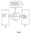
- the invention provides the directional control system and the control system of the running rate of motor or motors to be independent one with respect to the other, an interfacing and synchronization unit being provided having communications channels connected to communications lines 401 of the directional control system and of the control system of the running rate of motor or motors and of the reverser.
- Figure 4 shows such architecture.
- the directional control system disclosed in the present invention is indicated.
- the control system of the running rate of motor or motors is indicated.
- any further measuring or steerage and/or telecommunicating devices of marine vessel are indicated having at least a communications output coded according to any protocol for exchanging data and commands with further devices.
- the interfacing and synchronization unit is indicated.
- Such interfacing and synchronization unit comprises a CPU, a memory for a program synchronizing tasks of the two systems and at least a channel communicating with communications lines 401 of the directional control system and of the control system of the running rate of motor or motors and of the reverser.
- the synchronizing program it is possible for the synchronizing program to have a subroutine for controlling the tasks of the two systems.
- command signals of position or stroke of the steering mechanism and command signals of the running rate of motor or motors are supplied to the interfacing and synchronizing unit, while means for comparing said command signals with a reciprocal compatibility and congruity table are provided.
- Such table may correlate position ranges of the steering mechanism to ranges of the running rate of the motor that are compatible with said position gaps of the steering mechanism according to criteria for safety execution of steerage manoeuvrings with reference to the type of ship, at least an indication being generated when directional command signals and command signals of running rate of motor or motors are not within values included in said ranges.
- the interfacing and synchronizing unit may take the control of the directional system or of the system setting the running rate of the motor automatically correcting at least one signal of the directional command signals or running rate setting signals such to satisfy conditions defined in the correlation table.
- a further important task is the synchronized control of the transfer of control from a control station to another control station.
- Generally directional control elements and mechanisms controlling the running rate of motor and reverser are integrated in a common control station.
- the interfacing and communications unit automatically provides to deactivate the first station and to actuate the second station for both systems.
- a subroutine for transferring the disabling/enabling command that provides to generate a control signal disabling/enabling the control station for both directional control system and motor running rate control system. Modes con be carried out as the above with reference to a single station.
- the interfacing and synchronizing unit may provide additional inputs of signals generated by further devices or units such as a radar or sonar or a satellite system determining the position, compass signal, an automatic pilot system, data relevant to weather conditions and provided by tools measuring pressure, wind speed, wind direction, ecc, ecc.
- further devices or units such as a radar or sonar or a satellite system determining the position, compass signal, an automatic pilot system, data relevant to weather conditions and provided by tools measuring pressure, wind speed, wind direction, ecc, ecc.
- the interfacing and synchronizing unit may have different communications units working with different communications protocols and therefore it causes systems and devices working according to different communications protocols to feed or read data from said interfacing and synchronizing unit.
- actuating cylinder can be replaced with an electromechanical actuator or the like. In this case it is also possible to further simplify the system since it is not more necessary to provide the hydraulic circuit.
- the electromechanical transducer generating the electric signal correlated to the stroke made by the control element or to the position taken by the control element or the eventual associated electronic control and processing unit are connected to a device indicating the position set by the steering mechanism which position results from the stroke made by the control element or the position thereof, so called rudder angle, according to the correlation function provided in the working program.
- an electromechanical detector for the actual position of the steering mechanism that is the so called actual rudder angle, is associated to the hydraulic actuator and/or the shaft of the steering mechanism, the signal generated by said detector being transmitted to the electromechanical transducer or to the associated electronic control and processing unit and/or control and processing unit associated to the actuator moving the steering mechanism.
- One or both said control and processing units have a portion for comparing the nominal rudder angle set by the control element with the angular position actually taken by the steering mechanism, that is the actual rudder angle and which comparing portion generates warning and/or correction and/or error signals or it controls separate alarm circuits.
- means for detecting the route direction of the marine vessel are provided, such as a compass, a position detecting system GPS or a system for defining the position by means of electromagnetic signals, such as beacon signals or the like. These means generate electrical signals univocally correlated to the route direction.
- the comparing portion compares the nominal rudder angle set by the control element with the actual route direction of the marine vessel generating warning and/or correction and/or error signals or it controls separate alarm ciruits.
- the correction is an automatic one and so limits of correction angle of marine vessel direction and/or position correction of the steering mechanism are set.
- This task is very advantageous, for example during the navigation with quite rough sea, the steering determined by the wave being automatically corrected by the system without the need for the user to manually compensate the undesired steering determined by the wave. There may be a similar situation also with strong wind and/or currents.
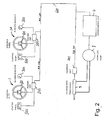
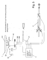
- Figures 5 and 8 show a second embodiment of electro-hydraulic steerage according to the present invention.
- the directional control element that is the steering wheel or rudder 101 is provided in combination with an angular position sensor (encoder).
- encoder 30 is composed of an optical movement sensor able to generate a pulse every 2° of rotation and of a digital direction discriminator.
- the encoder comprises a shielding disk 130 mounted coaxially to the steering wheel 101 and that can be rotate with said steering wheel 101.
- the shielding disk 130 has a row of through slots 230 having the same shape and span. Slots 230 have the same angular width and are alternated with full areas having the same angular width.
- an emitter 330 of eletro-magnetic radiation having a predetermined frequency preferably in the visual spectral range or infrared radiations is provided and which emitter 330 is oriented towards the shielding disk 130, that is the emitter emites radiations towards it.
- On the opposite side at least a pair of detectors of said radiation are provided transforming the radiation incident thereon in an electrical signal.
- the two detectors 430 are also arranged coinciding with the circular row of through solts 230, that is at the same radial distance from the axis of rotation of the shielding disk 130 and are faced with the sensitive surface thereof towards the shielding disk 130 and therefore towards the emitter.
- the rotation of the steering wheel causes the rotation of the shielding disk 130 and so the running of the row of slots 230 alternated with full areas between the emitter 330 and detectors 430.
- the electrical signal corresponding to the alternated exposure of the sensitive surface of the two detectors 430 to the radiation emitted by the emitter 330 is substantially a undulatory signal of the square wave or susbtantially square wave type. Due to a pulse counter per unit of time, not shown in details, that is a combination of a timer defining a time base and a counter, it is possible to count the number of pulses and so to determine the speed of rotation and rotation angular range made by the directional control element 101.
- the angular range can be detected by the fact that slots 230 have predetermined angular widths and angular distances therebetween defining angular feed steps of the shielding disk that can be detected by square wave signals provided by emitter/detector pairs 330, 430, so pulse count corresponds to a multiplying factor of the minimum angular step just defined by said constant angular widths of slots and/or angular distances between slots of the shielding disk 130.
- such sizes are set in such a way that each counted pulse corresponds to a rotation angular step of about 2°.
- the direction of rotation of the directional control element 101 and so of the shielding disk is detected by means of the two detectors 430.
- the latters are arranged at a angular distance one with respect to the other that is lower or higher than the angular distance between two slots 230 of the disk 130 or than a multiple of the distance between two slots 230 when the two detectors are intended to cooperate with two different slots that are not directly one next to the other.
- the angular distance between two detectors 430 is such that when one of the two detectors coincides perfectly with a slot 230, the other detector 430' overlaps only with half of sensitive surface thereof to the associated slot 230.
- figure 8 schematically shows the principle of the directional detector limiting the embodiment to a linear slider and not a circular one for simplicity reasons, such principle being applicable also to the circular type.
- the provision of the encoder allows to prevent the steering wheel 101 or any other control element to have rotation stop means and thus it allows the continuous free rotation of the steering wheel in one of the two directions. Therefore it is not necessary also to univocally define positions between the steering wheel and directional steering mechanisms for example when changing station or when actuating the system.
- the arrangement according to this second embodiment leaves any absolute position of the steering wheel 101 or any other directional control element out of consideration.
- the central processing and control unit has only to detect the position of the directional steering wheel, while the movement thereof and the speed of movement thereof depend only from the number of.pulses generated by detectors 430, 430' and from the speed at which the directional control element 101 rotates respectively, that is from the ratio between said number of pulses and the elapsed time.
- the embodiment according to figures 5 to 8 has at least a control panel and a user interface provided with led indicators, buttons and a buzzer for each station.
- the actuation of the steering mechanism for example a rudder blade, occurs by means of a hydraulic actuating cylinder supplied by a reversible hydraulic pump with a direct current motor.
- the electronic processing unit for managing the system is associated or provided in combination with the control unit of the pump and it is provided with a plurality of electric interfaces for receiving messages coming from both directional control mechanisms 101 of one or more stations working in turn one with respect to the other and from additional operating units provided as equipments on the ship and disclosed above with reference to the preceding embodiment.
- the hydraulic cylinder in use is an hydraulic cylinder of the standard type.
- the number of control stations may vary from a minimum of 1 to a maximum of 8, provided that such stations are coded with different part number, in order to avoid any interaction with the encoder by the system installer (configuration carried out during production).
- the system provides that to the directional control element 101 is connected an hydraulic pump 40 of the type that is traditionally used for hydraulic directional servocontrols of marine engines or ships, for example a pump of the type described in EP 1 382 845 by the same applicant.
- the pump has an axial piston rotor having an axis of rotation that, in the embodiment of figures 5 and 6, is integral rotationally connected with the axis of the steering wheel 101.
- the pump has connection piping 140, 240 to the hydraulic circuit for supplying the linear actuator, that is the hydraulic cylinder 9 of the directional mechanism and they can be connected or disconnected from said primary hydraulic circuit via a solenoid valve 41.
- a further security for the system has been generated made of a sort of hydraulic back-up of the electric control system. For example even if the power supply on board completely fails, at least one of the control station may control the steering mechanism by means of an hydraulic system that does not require any electrical supply.
- solenoid valve 41 may be of the type causing the disconnection of piping 140 and 240 from the primary hydraulic circuit only when there is eletrical supply, while it automatically goes in connecting condition of piping 140 and 240 and so the pump 40 when it is not supplied and that is when there is no electric supply.
- each installation will provide the provision of a safety button 42 with which the power supply to the solenoid valve 41 will be stopped and possibly also the power relay will be activated.
- system according to the embodiment of figures 5 to 8 may possibly comprise also a switch 6 connecting in turn to the power supply battery the electric portion of the directional control system or an emergency circuit for directly supplying the motor of the pump 8 analogously to what disclosed above for the first embodiment according to figures 1 to 4.
- the processing unit for operating the system in combination with the electro-hydraulic control unit (the pump + direct current motor), the solenoid valve as well as a power relay able to disconnect the control unit, are all advantageously housed inside a proper case for making easier the installation and maintenance of the system.
- the managing processing unit is made in such a way to interface with command signals for reversible control units and/or controls for solenoid valves, coming from external automatic pilots of third parties.
- the managing processing unit may receive tachymetric information coming from suitable external sensors.
- the system may automatically change some parameters, such as the steering wheel sensitivity on the basis of the ship speed and it may take all compatible tasks disclosed with reference to the preceding first embodiment of figures 1 to 4.
Landscapes
- Chemical & Material Sciences (AREA)
- Engineering & Computer Science (AREA)
- Combustion & Propulsion (AREA)
- Mechanical Engineering (AREA)
- Ocean & Marine Engineering (AREA)
- Steering Control In Accordance With Driving Conditions (AREA)
- Control Of Position, Course, Altitude, Or Attitude Of Moving Bodies (AREA)
Abstract
Description
at least a steering mechanism dipped or that can be dipped and that can rotate about an axis contained in a plane parallel to the longitudinal axis of the ship or coinciding with said axis, which steering mechanism can be moved between two opposite extreme positions each being corresponded or correlated with a maximum directional steering angle in one of two opposite directional steering directions of the marine vessel with respect to a straight travelling direction;
means for actuating the movement of said at least one steering mechanism between said two extreme positions;
at least a directional control station of the marine vessel wherein at least a control element is provided for setting the directional steering, which control element can be moved between two opposite extreme stop positions;
means for transmitting the movement stroke of the control element or the position of the control element with respect to the total stroke to means actuating the movement of said at least one steering mechanism, which transmitting means transform the control element stroke in signals for actuating actuators moving the at least one dipped steering mechanism according to a function univocally correlating the movement stroke or position of the control element within the total stroke thereof and the movement stroke or position of the dipped steering mechanism in such a way that a single and always the same position of the dipped steering mechanism with respect to the total stroke of said dipped steering mechanism is set for a specific position of the control element with respect to the total movement stroke thereof.
Claims (109)
- A directional control system for marine vessels, such as ships or the like, comprising:characterized in thatat least a steering mechanism dipped or that can be dipped and rotatable about an axis contained in a plane parallel to the longitudinal axis of the ship or coinciding with said axis, which steering mechanism can be moved between two extreme opposite positions each one being corresponded or correlated with a maximum directional steering angle in one of the two opposite directional steering directions of the marine vessel with respect to a straight travelling direction;means actuating the movement of said at least one steering mechanism between said two extreme positions;at least a directional control station for the marine vessel wherein at least a control element is provided for setting the directional steering, which control element can be moved in two directions opposite one with respect to the other;means for transmitting the movement stroke of the control element or the position of the control element as regards the total stroke with respect to two opposite extreme stop positions, to means actuating the movement of said at least single steering mechanism, which trasmitting means transform the control element range in activation signals for actuators moving the at least one dipped steering mechanism according to a function univocally correlating the movement stroke or position of the control element within the total stroke thereof and the movement stroke or position of the dipped steering mechanism such that for a specific movement stroke or a specific position of the control element with respect to the total movement stroke thereof a single and ever-identical movement stroke or position of the dipped steering mechanism is set with regard to the total stroke of said dipped steering mechanism,
means for trasmitting the movement stroke of the control element or the position of the control element with respect to the total stroke to means for actuating the movement of said at least single steering mechanism are electrical type means. - The system according to claim 1, characterized in that an electromechanical or optical transducer is associated to the movable control element generating an electrical signal that is univocally correlated to the range made by the control element or to the position taken by the control element with respect to the total stroke thereof.
- The system according to claims 1 or 2, characterized in that the control elements are of the type that can rotate about an axis or can angularly moved, such as a steering wheel, a rudder wheel or a rudder tiller, and transducers consisting of optical, magnetic, electromagnetic encoders or potentiometers or the like, the potentiometer slider being mechanically coupled to the shaft of rotation or angular movement of the control element and encoders being associated to the control element such to transform the angle of rotation thereof in a corresponding signal.
- The system according to claim 3, characterized in that potentiometers have a rotating slider the spindle of the slider being connected to the shaft of the control element directly or by means of a reduction unit.
- The system according to claim 3, characterized in that transducers associated to movable directional control elements consist of an optical encoder having means for generating an optical pulse for minimum unit movement steps of the movable directional control element and a counter for said pulses generating a signal corresponding to the number of counted pulses which forms the electrical signal univocally correlated to the movement stroke of said directional control element and means for transmitting said signal to means actuating the movement of said at least one steering mechanism transforming said signal in a movement control signal of said directional mechanism proportional to the movement stroke of the movable directional control element.
- The system according to claim 5, characterized in that it comprises an emitter/receiver pair which are arranged opposite one with respect to the other, said emitter being faced with the emitting side towards the receiving side of the receiver and said emitter and said receiver being spaced one with respect to the other, while a shielding element is provided therebetween which is movable in two opposite directions and it is dinamically connected to the movable directional control element, while said shielding element has a row of through slots and not transparent areas alternated one with respect to the other which row extends parallely to the direction of movement and whose movement path passes between the emitter and the receiver of said emitter/receiver pair.
- The system according to claim 6, characterized in that the emitter/receiver pair comprises an emitter of radiation in the infrared spectral, range and a receiver sensitive to the radiation in the infrared spectral range.
- The system according to claim 6, characterized in that the shielding element consits of a disk that is rotatable mounted coaxially and together with the movable directional control element the row of through slots and not transparent areas alternated one with respect to the other being provided on a circumference of said disk whose radius corresponds to the radial distance of emitter/receiver pair from the axis of rotation of said circular shape shielding element.
- The system according to one or more of the preceding claims 5 to 8, characterized in that the encoder comprises at least two, preferably three emitter/receiver independent pairs located along the path or extension of the row of through slots.
- The system according to one or more of the preceding claims 5 to 9, characterized in that the optical encoder comprises means for detecting the direction of movement of the movable directional control element generating a signal corresponding to said detected direction, which signal is transmitted to means actuating the movement of the at least one steering mechanism.
- The system according to claim 10, characterized in that each emitter/receiver pair comprises at least two receivers placed one next to the other with reference to the direction of movement of the shielding element that is the row of through slots which two receivers are spaced one with respect to the other more or less than the distance between two subsequent through slots or than a multiple of said distance and to such extent that the difference between the distance of the two receivers and the distance between two subsequent through slots or an integral multiple of said distance, corresponds to a fraction of the distance between two subsequent through slots, thereby when a first receiver perfectly coincides with a through slot the second receiver coincides only with a portion of a second through slot, while pulse trains generated by said two receivers have a phase difference whose absolute value corresponds to said difference between the distance of the two receivers and the distance between two subsequent through slots or an integral multiple of said distance and the sign of said difference being positive or negative according to the direction of movement of the shielding element and so of the movable directional control element, a signal corresponding to the value of said sign being generated.
- The system according to on or more of the preceding claims, characterized in that control actuators of the dipped steering mechanism consist of an electrical actuator such as an electrical rotary motor or a linear electromechanical actuator, the electrical signal univocally correlated to the stroke or position of the control element being provided as the control signal thereof to a unit for power supplying the electrical motor and/or the linear electromechanical actuator.
- The system according to claim 12, characterized in that the power supply unit energizes the electrical motor or the linear electrical actuator for a length of time necessary to provide the stroke or to reach the position of the steering mechanism univocally correlated to the stroke or position of the control element that are transmitted as electrical signal, a fixed movement speed of the steering mechanism being provided or a maximum and a minimum movement speed of the steering mechanism are provided said steering mechanism being moved at a speed that is the same or proportional to the movement speed of the control element when the movement speed of the control element is included or it results in speeds included within said maximum speed and said minimum speed and the steering mechanism being moved with respect to said minimum speed and said maximum speed when the movement speed of the control element is the same or it results in speeds of the steering mechanism that correspond to said maximum speed and to said minimum speed.
- The system according to one or more of the preceding claims 5 to 11, characterized in that transducers associated to movable directional control elements consist of an optical encoder having means for generating an optical pulse for minimum unit movement steps of the movable directional control element and a counter for said pulses generating a signal corresponding to the number of counted pulses, which forms the electrical signal univocally correlated to the movement stroke of said directional control element a timer for generating a time base and means for determining the number of pulses counted in the time unit being further provided, while the signal transmitted to means for actuating the movement of said at least one steering mechanism comprises information about the total number of counted pulses and the number of pulses counted in the time unit and means actuating the movement of said at least one steering mechanism transform said signal into a movement control signal of said directional mechanism for a stroke and a movement speed proportional to the movement stroke of the movable directional control element and to the movement speed thereof respectively.
- The system according to one or more of the preceding claims, characterized in that the electrical actuator such as the electrical motor or the linear electromechanical actuator controls or drives a pump or an hydraulic motor driving an hydraulic actuator, which pump or hydraulic motor and which hydraulic linear actuator are provided in a closed hydraulic circuit for driving the steering mechanism.
- The system according to claim 15, characterized in that said hydraulic system driving the steering mechanism is locally provided in the region of the steering mechanism, particularly in the region of the shaft of rotation or angular movement of the steering mechanism.
- The system according to one or more of the preceding claims, characterized in that instead of the hydraulic system driving the steering mechanism a mechanical system driving the steering mechanism is provided having transmission cables or tie rods the electrical motor or the linear electromechanical actuator being dinamically connected to said cables or tie rods for driving the steering mechanism.
- The system according to claim 17, characterized in that the mechanical system driving the steering mechanism is locally provided near said steering mechanism and when said steering mechanism has a shaft of rotation at said shaft.
- The system according to one or more of the preceding claims, characterized in that it comprises:at least a steering mechanism dipped or that can be dipped and rotatable about an axis contained in a plane parallel to the longitudinal axis of the ship or coinciding with said axis, which steering mechanism can be moved between two extreme opposite positions each one being corresponded or correlated with a maximum directional steering angle in one of the two opposite directional steering directions of the marine vessel with respect to a straight travelling direction;at least a directional control station for the marine vessel wherein at least a control element is provided for setting the directional steering, which control element can be moved in two opposite directions;electromechanical or electro-optical transducer means for the movement stroke of the control element or for the position of the control element with respect to the total stroke between two extreme opposite stop positions which transducers generate an electrical signal that is univocally correlated to the movement stroke of the control element or to the position of the control element with respect to the total stroke;a unit for power supplying an electrical motor, which power supply unit is connected to the electromechanical transducer associated to the control element and it receives the electrical signal generated by said transducer;an hydraulic circuit driving the steering mechanism comprising a double-acting linear actuator and a pump for feeding the hydraulic fluid to said hydraulic actuator;means for reversing the fluid flow under pressure to the double-acting hydraulic actuator consisting of a combination of electrically controlled valves or a reversible pump;which hydraulic pump is driven by the electrical motor and which possible electrically controlled valves reversing the direction of fluid flow under pressure to the hydraulic actuator are controlled by the power supply unit of the electrical motor;so that the stroke of the control element causes the actuator moving the dipped steering mechanism to be driven according to a univocal function correlating the movement stroke or position of the control element within the total stroke thereof and the movement stroke or position of the dipped steering mechanism.
- The system according to claim 19, characterized in that only the power supply unit and/or the electromechanical transducer associated to the steering control element are associated to intelligent local dedicated units or integrate intelligent local dedicated units.
- The system according to claim 20, characterized in that only the power supply unit and/or the electromechanical transducer or the optical encoder have a control and processing electronical portion comprising a processing unit or a CPU, at least an input portion and at least an output portion consisting of communications units working according to a predetermined communications protocol.
- The system according to claim 21, characterized in that a control and processing electronical portion is associated only to the power supply unit, while to the optical encoder only a unit converting signals of said encoder in digital signals and generating a communication message is associated comprising data about the total number of pulses and possibly about the number of pulses in time unit and possibly about the phase difference among pulses of the two receivers of the emitter/receiver pair according to a predetermined communications protocol for said control and processing electronic portion associated to the power supply unit.
- The system according to claims 21 or 22, characterized in that to the processing portion or CPU a program memory is associated wherein a working program of the transducer and/or power supply unit is loaded.
- The system according to one or more of the preceding claims 20 to 23, characterized in that the working program comprises algorithm computating the function for univocally correlating the position or stroke of the control element and the position or stroke of the steering mechanism.
- The system according to one or more of the preceding claims, characterized in that the correlation function may be in the form of a computational algorithm that is executed each time the control element is driven or in the form of a correlation table stored inside the memory of the corresponding control unit, that is the electromechanical transducer or the associated unit and/or power supply unit.
- The system according to one or more of the preceding claims, characterized in that it provides a data or command communications protocol among individual control units that is called BUS CAN or other communications protocols as LAN or the like.
- The system according to one or more of the preceding claims, characterized in that to the electromechanical transducer or optical encoder generating the electrical signal correlated with the stroke made by the control element or the position taken by the control element or the possible associated electronic control and processing unit there is connected a device indicating the position set by the steering mechanism that according to the correlation function provided in the working program results from the stroke made by the control element or the position thereof, the so called rudder angle.
- The system according to one or more of the preceding claims, characterized in that it provides an electromechanical detector for the actual position of the steering mechanism, namely the so called actual rudder angle, which is associated to the hydraulic actuator and/or to the shaft of the steering mechanism the signal generated by said detector being transmitted to the electromechanical transducer or to the associated electronic control and processing unit and/or to the control and processing unit associated to the actuator moving the steering mechanism, while one or both said control and processing units have a portion for comparing the nominal rudder angle set by the control element and the angular position actually taken by the steering mechanism, that is the actual rudder angle and which comparing portion generates warning and/or correction and/or error signals or it controls separate alarm circuits.
- The system according to one or more of the preceding claims, characterized in that it comprises means for detecting the navigation direction of the marine vessel, such as a compass, a position detecting system GPS or a position detecting system by means of electromagnetic signals, such as beacon signal or the like, which means generate electrical signals that are univocally correlated to the navigation direction, to the electromechanical transducer generating the electrical signal correlated to the stroke made by the control element or the position taken by the control element or the possible associated electronic control and processing unit there being connected a device for indicating the position set by the steering mechanism that according to the correlation function provided in the working program results from the stroke made by the control element or the position thereof, the so called rudder angle, while a portion for comparing the nominal rudder angle set by the control element and the actual navigation direction of the marine vessel is provided which comparing portion generates warning and/or correction and/or error signals or it controls separate alarm circuits.
- The system according to one or more of the preceding claims 27 to 29, characterized in that the comparing portion consists of a comparing subroutine of the control and processing program stored in the control and processing unit associated to the electromechanical transducer and/or actuator moving the steering mechanism.
- The system according to one or more of the preceding claims 27 to 30 characterized in that limits for the angle correcting the marine vessel direction and/or correcting the position of the steering mechanism are provided.
- The system according to one or more of the preceding claims, characterized in that the power supply unit generates a control signal for the electrical motor driving mechanical means for moving the steering mechanism or the pump driving the actuating cylinder corresponding to a predetermined fixed speed for moving the steering mechanism which speed is independent of the movement speed of the control element.
- The system according to one or more of the preceding claims, characterized in that the power supply unit has means for setting said movement speed of the steering mechanism said speed can be set between a minimum speed and a maximum speed.
- The system according to claim 33, characterized in that the power supply unit activates the movement of the steering mechanism at a speed correlated to the movement speed of the control element when the speed of the steering mechanism is within the range between said minimum speed and said maximum speed.
- The system according to claims 33 or 34, characterized in that the power supply unit comprises a memory wherein a table of possible movement speeds of the steering mechanism is stored with reference to said fixed movement speed and/or said minimum and maximum speed and selecting means being provided that can be operated by the user for setting the fixed movement speed or minimum and maximum movement speed of the steering mechanism among the ones provided in the table.
- The system according to claim 35, characterized in that a subroutine for selecting and changing said fixed speed and/or minimum speed and/or maximum speed is provided in the working program.
- The system according to one ore more of the preceding claims, characterized in that commands for setting and/or selecting said movement fixed and/or minimum and/or maximum speed of the actuating mechanism are set by the user by means of selecting and/or setting and/or selection confirmation and/or setting confirmation means locally provided in the steering control station and are transmitted to the power supply unit of the hydraulic pump motor via the control and processing unit associated to the electromechanical transducer of the control element.
- The system according to one or more of the preceding claims, characterized in that it comprises means for determining the navigation speed of the marine vessel and/or the running rate of motor or motors, which means provide a signal corresponding to said navigation speed and/or to said running rate of motor or motors, and which signal or signals are provided to the power supply unit of the electrical motor driving mechanical means for moving the steering mechanism or pump supplying the hydraulic cylinder, the ratio between movement speed of the steering mechanism and movement speed of the control element being changed by said power supply unit on the basis of said navigation speed and/or said running rate of motor or motors.
- The system according to claim 38, characterized in that the power supply unit of the electrical motor driving mechanical means for moving the steering mechanism or pump supplying the hydraulic cylinder changes or sets the value of movement fixed speed or maximum speed and minimum speed of the steering mechanism on the basis of said navigation speed and/or said running rate of motor or motors.
- The system according to claims 38 or 39, characterized in that the power supply unit comprises a memory wherein a table of possible movement speeds of the steering mechanism is stored with reference to said fixed movement speed and/or said minimum and maximum speed on the basis of predetermined and different navigation speeds and/or predetermined and different running rate of motor or motors.
- The system according to one or more of claims 38 to 40, characterized in that in the working program there is provided a subroutine for detecting said navigation speed and/or said running rate of motor or motors, and for automatically changing and selecting said movement fixed speed and/or minimum speed and/or maximum speed of the steering mechanism on the basis of said navigation speed and/or said running rate of motor or motors.
- The system according to one or more of the preceding claims, characterized in that it comprises means for manually selecting and setting the automatic mode or the manual mode for determining the fixed movement speed and/or maximum and minimum speed of the steering mechanism.
- The system according to one or more of the preceding claims, characterized in that in combination it provides an emergency system in case of non operation of transmission or communications among means driving the steering mechanism and power supply unit of said driving means and/or the control element said emergency system can be activated by means of a switch that can be at least manually driven commuting power supply inputs of the motor driving mechanical means moving the steering mechanism or pump supplying the actuator moving the steering mechanism directly to outputs of a power supply electromechanical unit controlled by buttons.
- The system according to claim 43, characterized in that said power supply electromechanical unit comprises a power portion such as a remote control switch or a power electrical circuit that are controlled by control manual means such as two buttons or a lever or the like, for energizing the motor in one direction and in the opposite one.
- The system according to one or more of the preceding claims, characterized in that electronic control and processing units associated to the control element and actuators driving the steering mechanism are provided in combination with system operation parameter sensors sending system state signals to said units there being provided automatic means activating the emergency system and possibly means for indicating activation/disactivation of said emergency system or at least means for indicating the need to activate the emergency system that are controlled by one or more of said electronical control and processing units.
- The system according to one or more of the preceding claims, characterized in that it comprises means for changing the function correlating the position of the control element and the position of the steering mechanism.
- The system according to claim 46, characterized in that said means change the correlation function on the basis of the marine vessel steering angle.
- The system according to claims 46 or 47, characterized in that the function correlating the position of the control element and the position of the steering mechainsm is changed for movement ranges of the control element.
- The system according to one or more of the preceding claims 46 to 48, characterized in that the control and processing unit associated to the control element and/or the control and processing unit associated to the actuator moving the steering mechanism comprise a memory for an algorithm computating at least one preferably two or more functions correlating the position of the control element and the position of the steering mechanism or a table correlating the position of the control element and the position of the steering mechanism for each correlation function, means for selecting a correlation function and/or a correlation table and means for selecting limit positions defining one or more different movement ranges of the control element and/or of the steering mechanism being provided and a subroutine for setting the function correlating the position of the control element and the position of the steering mechanism being provided that is part of the working and control program and that can be called up and executed by one or more of said control and processing units, while there are provided means for indicating/displaying selected and/or confirmed settings and means for indicating the loading and execution of the routine changing the function correlating the position of the control element and the position of the steering mechanism.
- The system according to one or more of the preceding claims 46 to 49, characterized in that means for changing the function correlating the position of the control element and the position of the steering mechanism, change the control signal generated by the control element and by the associated electromechanical transducer and/or by the associated control and processing unit.
- The system according to claims 49 and 50, characterized in that it has means for inputting a command changing the correlation function or parameters thereof, means for selecting and calling up stored values of parameters or of correlation functions or for inputting values of parameters or correlation functions and means for inputting the selection confirmation and/or confirmation of parameters or of the inputted correlation function, as well as a memory or a memory area for said parameters of the correlation function and/or for different correlation functions, while the control and working program of the rudder unit and/or motor control unit has a subroutine for changing the correlation function and/or parameters of the correlation function that writes and reads said function and/or said parameters in the memory dedicated thereto, and it addresses the control and working program to the function or to parameters selected by the user or to the function and to parameters selected by the manufacturer or installer of the system.
- The system according to one or more of the preceding claims, characterized in that it comprises a detector for the steering angle set by the control element that is the set nominal steering angle and a detector for the actual position of the steering mechanism and/or a detector for the navigation direction of the marine vessel, means for compensating the differences between the set nominal angle and the actual angle and/or the navigation direction of the marine vessel being provided.
- The system according to claim 52,
characterized in that the control and working program of the control element and/or of the actuator moving the steering mechanism comprise an automatized subroutine for compensating mechanical, hydraulic and eletrical tolerances of the two system portions. - The system according to one or more of the preceding claims, characterized in that it has means for reversing the movement direction of the control element with respect to the resulting movement direction of the steering mechanism.
- The system according to claim 54, characterized in that it has means indicating if the reversing condition is in operation or not in operation.
- The system according to claims 54 or 55, characterized in that it has means for inputting an activation/disactivation command for the reversal that are connected to the control and processing unit associated to the control element and/or to the actuator moving the steering mechanism, which means activate a reversing subroutine provided in the control and working program.
- The system according to one or more of the preceding claims, characterized in that it has means for setting virtual stop positions of the control element and/or of the steering mechanism.
- The system according to claim 57, characterized in that it has mechanical stop means for the control element and/or the steering mechanism, means for inputting a command activating the function defining stop positions are provided, which signal activates alternative control means for moving the steering mechanism in the two different movement stop positions which alternative control means for moving the steering mechanism are independent of the activation of the control element and by-pass the control element and which signal simultaneously activates means for disabling the control element to transmitt command signals to actuators moving the steering mechanism, and further a writing memory for the control signal correlated to the position of the control element and/or steering mechanism and means for storing said signal as the signal corresponding to the central position of the control element and/or steering mechanism being provided.
- The system according to claims 57 or 58, characterized in that the control and working program of the control and processing unit associated to the control element and/or of the control and processing unit associated to the steering mechanism comprise a subroutine setting stop positions of the control element and/or steering mechanism, which subroutine is activated by control means for executing thereof and which subroutine provides the automatic movement activation of said steering mechanism in a first movement direction towards a first mechanical stop independently from the control element and the disabling of transmission of command signals for the control element and said subroutine providing the manual movement of the control element in a first stop position corresponding to the stop position of the steering mechanism and the subsequent recording of signals relevant to said first stop positions of the control element and of the steering mechanism activated by recording control means, while then said subroutine provides the movement of the steering mechanism that is automatic and independent of the control element in a second mechanical stop position and said subroutine providing the manual movement of the control element in said second mechanical stop position corresponding to said second stop position of the steering mechanism and the subsequent recording of signals relevant to said second stop positions of the control element and of the steering mechanism which recording is activated by recording control means.
- The system according to one or more of the preceding claims 57 to 59, characterized in that position signals of the control element and/or steering mechanism that are relevant to positions thereof upstream of actual mechanical stop positions with respect to the direction approaching the corresponding stop position are automatically stored as stop positions.
- The system according to one or more of the preceding claims, characterized in that it provides means for determining the central position of the steering mechanism and of the control element.
- The system according to claim 61, characterized in that for the control element and/or the steering mechanism it has means for inputting a command activating the function defining central positions of the control element and/or steering mechanism, which command activates alternative control means moving the steering mechanism in the central position that determine said central position on the basis of the two opposite stop positions and which alternative control means moving the steering mechanism are independent of the activation of the control element and by-pass the control element and which signal simultaneously activates means for disabling the control element to transmit command signals to actuators moving the steering mechanism, and further a writing memory for the control signal correlated to the position of the control element and/or steering mechanism and writing control means for said signal as the signal corresponding to the central position of the steering mechanism being provided.
- The system according to claim 61 or 62, characterized in that the control and working program of the control and processing unit associated to the control element and/or of the control and processing unit associated to the steering mechanism comprise a subroutine setting central positions of the control element and/or steering mechanism, which subroutine is activated by control means for executing thereof and which subroutine provides the automatic activation determining said central position of the steering mechanism by means of position signals relevant to two opposite stop positions of the steering mechanism and the movement of said mechanism in said central position independently of the control element and the disabling of transmission of command signals for the control element and said subroutine providing the manual movement of the control element in a central position corresponding to the central position of the steering mechanism and the subsequent recording of signals relevant to said central positions of the control element and of the steering mechanism which recording is activated by recording control means.
- The system according to one or more of claims 61 to 63, characterized in that the central position of the control element, that is the signal generated therefrom is compared with the central position of said control element that is computed on the basis of stored stop positions thereof.
- The system according to one or more of the preceding claims 61 to 64, characterized in that there are provided means for indicating the coincidence condition of the set position of the control element with the central position of the control element which is computed on the basis of stored stop positions for the control element.
- The system according to one or more of the preceding claims, characterized in that it has means for re-setting, selecting and activating different virtual stop positions of the control element and/or steering mechanism.
- The system according to one or more of the preceding claims, characterized in that in the control and processing unit associated to the control element and/or in the control and processing unit associated to the steering mechanism there is provided a memory wherein a working program with a system inizialization or activation subroutine is stored, which subroutine controls in disabling condition the control element when it is connected to the power supply, while provides to enable the control element when it is moved in a position corresponding to the position of the steering mechanism when the system is activated.
- The system according to claim 67, characterized in that it provides means for inputting a command requiring enabling/disabling of the control station.
- The system according to one or more of the preceding claims, characterized in that the control and processing unit associated to the control element and/or the control and processing unit associated to the steering mechanism comprise at least a diagnostic portion to which one or more sensors detecting operation parameters of electrical and/or electronic operating units and of mechanical and/or hydraulic operating units are connected and which diagnostic portion compares operation parameter values of operating units of the system with values of corresponding parameters stored in a memory and which portion generates commands of indicator means or error messages that can be displayed on monitors or by combinations of visual and acustic signals or means activating separate alarm systems such as relay or the like, when detected parameter values deviate from stored values of said parameters more than a predetermined tolerance.
- The system according to claim 69, characterized in that the diagnostic portion comprise a memory wherein there is stored a table correlating error messages and information about the gravity of the error to combinations of predetermined values or deviations from stored values of predetermined operation parameters of system operating units, said messages and said information about the gravity of the error being displayed when corresponding combinations of predetermined values or deviations from stored values of predetermined operation parameters of system operating units occur.
- The system according to claims 68 to 70, characterized in that the diagnostic portion provides means for generating command signals of the steering mechanism replacing at least partially command signals generated by the control element or changing said command signals of the control element or at least partially disabling said command signals for at least partially executing the system tasks.
- The system according to one or more of claims 68 to 71, characterized in that the diagnostic portion provides means for changing the response of the actuator moving the steering mechanism to command signals transmitted by the control element.
- The system according to one or more of the preceding claims, characterized in that the diagnostic portion provides the automatic activation of the emergency system.
- The system according to one or more of the preceding claims, characterized in that sensors for one or more of following operation parameters of system operating units are provided: detecting absence or defect in the analogue signal generated by the potentiometer or by another electromechanical transducer driven by the control element, detecting absence of steering control signal on the communications line, error condition of the rudder, stop setting absent or not correct, control signal with parameters out of re-set parameters, reaching the limit of absorbed current by eletrical motor that controls mechanical mechanisms moving the steering mechanism or the hydraulic pump, absence of life signal of motor generated by motor itself or by an associated detector, overheating of the power portion of the control board of motor that controls mechanical mechanisms moving the steering mechanism or of the pump detected by one or more temperature sensors connected to corresponding inputs of the diagnostic portion of the control unit of the motor that controls mechanical mechanisms moving the steering mechanism or of the pump, lack of coherence between motor control and movement of actuating cylinder, defects of the unit detecting the position of the steering mechanism, unsuccessful reception of received indication of data by unit detecting the position of the steering mechanism, the signal of the unit detecting the position of the steering mechanism is beyond higher and lower limit, absence or non correctness of the analogue input signal to the unit detecting the position of the steering mechanism and generated by the detector of the position of the steering mechanism or of actuating cylinder, unsuccessful reception of stop data, absence of signal of the unit detecting the position of the steering mechanism, wrong response of the cylinder with respect to the movement of the control element, power supply voltage of electronic circuits too low or too high, power supply voltage of the control unit of the pump motor too high or too low, power stage selfprotection, anomalous reset of the control element and/or motor and/or unit detecting the position of the steering mechanism, memory check.
- The system according to one or more of the preceding claims, characterized in that the diagnostic portion consists of a subroutine of the control and working program for the control and processing unit associated to the control element and/or to the steering mechanism.
- The system according to one or more of the preceding claims, characterized in that the diagnostic portion is activated when the system is activated and/or inizialized and during operation of the system.
- The system according to one or more of the preceding claims, characterized in that it comprises a diagnostic portion changing the function correlating the position or stroke of the control element and the position or stroke of the steering mechanism.
- The system according to one or more of the preceding claims, characterized in that it comprises at least two directional control stations, each provided with a control element made with tasks according to one or more of the preceding claims each control station being provided with means for inputting commands enabling/disabling said station and with means indicating the enabling or disabling condition of the station as well as with means for univocally identifying the station and control and processing units associated to control elements of various stations and/or associated to the steering mechanism being provided with means inhibiting the command enabling a station in the presence of a enabling condition signal of a furhter station.
- The system according to claim 78, characterized in that each control station has enabling/disabling means providing to enable the station when a signal enabling a different control station is not present and when the position of the control element corrisponds to the position of the steering mechanism.
- The system according to claim 78, characterized in that each control station has means for partially activating thereof and inhibiting the transmission of control signal of the control element or the reception of the control signal by the control and processing unit associated to the steering mechanism till the position of the control element of said station corresponds to the position of the steering mechanism according to the set correlation function, the transmission of the control signal of the control element being automatically enabled when the control element takes the position corresponding to the position of the steering mechanism.
- The system according to one or more of the preceding claims, characterized in that it is provided in combination with an electromechanical system controlling the operation condition of one or more motors and reverser of one or more motors, which system controlling the operation condition of one or more motors has at least a control portion provided in at least a station controlling the operation condition of motor or motors generating command signals transmitted via a communications line to an actuating portion that controls mechanisms changing the operation condition of motor or motors, the steering control system and the system controlling the operation condition of motor or motors and of the reverser being composed of two separate and independent systems and directional control elements of the directional control system and elements controlling the operation condition of motor or motors being integrated in a common control station, while the two system communicates with a common interfacing and synchronizing unit, which interfacing and synchronizing unit has at least a memory where an interfacing and synchronizing program is loaded or can be loaded coordinating monoeuvrings of one system with monoeuvrings of the second system.
- The system according to claim 81, characterized in that the interfacing and synchronizing unit comprises means for inhibiting command signals of the directional control system and/or inhibiting control signals of motor or motors operation when said signals correspond to combinations of operation conditions of motor or motors and/or route steering conditions that are conflictual or dangerous, said combinations being stored in a memory of the interfacing and synchronizing unit.
- The system according to claims 81 or 82, characterized in that it comprises variuos control stations wherein directional control means and means controlling the operation condition of motor or motors are integrated, while each control station has common means for enabling/disabling itself, in the interfacing and synchronizing unit being provided a memory for a program transferring the control and command among individual stations which program at the same time transfers the directional control and motor control to the same station.
- The system according to one or more of the preceding claims, characterized in that the interfacing and synchronizing unit has channels communicating with operating units such as instruments estimating weather and sea conditions, speedometer, sonar, radar devices or equipement detecting the satellite position, automatic pilot devices, stored in a memory of the interfacing and synchronizing unit there being provided automatic programs estimating data provided by said operating units and changing the navigation direction or the operation conditions of motor on the basis of data provided by said operating units, said interfacing and synchronizing unit being provided with converters of signals provided by directional control systems and by the system controlling the motor operation and signals sent therefrom and signals provided by operating units from the specific coding protocol of said systems and said operating units in a common coding protocol used by programs that can be executed by the interfacing and communications unit.
- The system according to one or more of the preceding claims, characterized in that it comprises hydraulic actuating means moving the steering mechanism that are alternate to main actuating means according to one or more of the preceding claims and are directly controlled with hydraulic transmission by at least a directional control element of at least a control station.
- The system according to claim 85, characterized in that said at least one control station has means for actuating/disactuating main actuating means moving the steering mechanism.
- The system according to claims 85 or 86, characterized in that it comprises at least a directional control element dinamically connected to the shaft driving a reversible pump supplying an actuating cylinder moving the steering mechanism of an alternative circuit, said pump being connected by its inputs/outputs to a main circuit supplying said actuating cylinder moving the steering mechanism by means of one or more servo-controlled valves coupling/uncoupling said inputs/outputs to said main hydraulic circuit and which main circuit comprises a main pump supplying said cylinder that is driven by eletrical motor that in turn is driven by a supply unit activated by eletrical signals transmitted to said supply unit and generated by a directional control element.
- The system according to claim 87, characterized in that said servo-controlled valve or valves coupling/uncoupling said inputs/outputs to said main hydraulic circuit are solenoid valves of the type intended to take the coupling condition of said inputs/outputs to said main hydraulic circuit when there is no power supply or in case of system failure and uncoupling condition when there is power supply and normal operation conditions of the system.
- The system according to one or more of claims 85 to 88, characterized in that it has a power relay for enabling/disabling the electrical motor for driving the pump supplying the actuating cylinder moving the steering mechanism which pump is provided in the main hydraulic circuit, which relay can be manually or automatically controlled depending on failure condition or normal operation of the system.
- A directional control method for marine vessels or the like, by means of a control element movable between two extreme positions and at least a steering mechanism whose position affects the marine vessel direction and it is controlled by the direction control element position, which method comprises following steps:a) generating a directional control signal univocally correlated to the position and/or stroke of the directional control element;b) coding said directional control signal according to a predetermined communications protocol;c) transmitting said directional control signal to an actuating unit;d) processing said directional control signal transforming it in a control signal of an actuator moving the steering mechanism for moving said steering mechanism in a route steering position corresponding to the position of the directional control element.
- The method according to claim 90, characterized in that the processing of the directional control signal in a control signal of an actuator moving the steering mechanism comprises the execution of a function correlating the directional control signal and the control signal of the actuator moving the steering mechanism.
- The method according to claim 91, characterized in that it comprises the further step of selecting and/or setting parameters of the correlating function and/or selecting and/or setting one of various correlating functions.
- The method according to claims 90 to 92, characterized in that it comprises steps of defining stop positions of the directional control element and of the steering mechanism, for the steering mechanism being provided two opposite extreme mechanical stop positions and said steps consisting of:moving the steering mechanism independently of the directional control element in a first stop position;defining a virtual stop position of the steering mechanism corresponding to a position upstream of the mechanical stop position with respect to the approaching direction to said mechanical stop;storing the signal relevant to said first virtual stop of the steering mechanism;manually moving the directional control element in a first stop position, in the inhibited reception or transmission condition of directional command signals generated therefrom,storing the signal relevant to said first stop position of the directional control element,moving the steering mechanism in the second opposite mechanical stop position independently of the directional control element,storing a second virtual stop corresponding to a position signal of the steering mechanism upstream of said second mechanical stop with respect to the approaching direction to said second mechanical stop,manually moving the directional control element in a second stop position in the inhibited reception or transmission condition of directional command signals generated therefrom,storing the signal relevant to said second stop position of the directional control element.
- The method according to one or more of the preceding claims, characterized in that it comprises the steps of defining the central position of the steering mechanism and of the directional control element, which steps are:computing the signal corresponding to the central position of the steering mechanism between the first and the second mechanical and/or virtual stop,moving the steering mechanism independently of the directional control element in the position corresponding to said computed signal and storing said signal as the central position signal,moving the directional control element in a desired central position in the inhibited reception or transmission condition of directional command signals generated therefrom,storing the signal corresponding to said central position as the central position signal of the directional control element.
- The method according to claim 92, characterized in that the signal relevant to a central position of the directional control element is computed on the basis of stop signals thereof, while the fact of having reach said computed central position of the directional control element is indicated when the signal generated by the directional control element with the movement thereof coincides within predetermined tolerances with the signal corresponding to the computed central position.
- The method according to one or more of the preceding claims 90 to 95, characterized in that it comprises an inizialization process when the system is activated, which process has steps of keeping disactivated the transmission and/or reception of directional command signals of the directional control element or stopping the action of directional command signals until said signals correspond to the position of the steering mechanism, and activating the transmission or reception of said directional command signals or enabling the action thereof when the corrispondence condition between the directional control signal and the position of the steering mechanism is reached.
- The method according to one or more of the preceding claims 90 to 96, characterized in that it provides a process for transferring the directional control between at least two or more different control elements provided in corresponding control stations having a different position on the marine vessel, which process provides steps of generating a code indentifying each directional control station , disabling the transmission and/or reception of directional command signals of all stations, enabling the transmission and/or reception of the directional control signal only when the signal generated by the directional control element of the selected station corresponds to the position of the steering mechanism.
- The method according to claim 97, characterized in that it provides the automatic enabling of the selected station when the signal generated by the directional control element of said station corresponds to the position of the steering mechanism.
- The method according to one or more of the preceding claims 90 to 98, characterized in that it comprises a process indicating errors or mulfunctions that provides the following steps:detecting operation parameters of operating units of the directional control system,comparing said operation parameters with value combinations thereof corresponding to error and malfunction conditions,generating an error message that is specific univocally correlated for each value combination of said error or mulfunction parameters.
- The method according to claim 99, characterized in that it provides further steps of changing functions correlating directional command signals and command signals moving the steering mechanism on the basis of the combination of system operation parameters corresponding to predetermined and specific error or malfunction not fatal conditions.
- The method according to one or more of the preceding claims, characterized in that it provides the transformation of directional command signals in command signals driving an eletrical motor driving mechanical means moving the steering mechanism or of an hydraulic pump supplying an hydraulic cylinder moving the steering mechanism.
- The method according to one or more of the preceding claims, characterized in that it provides in combination a system controlling operation conditions of the motor, said system being separated from the directional control system and which method provides steps synchronizing the two systems consisting of:transforming directional command signals and signals controlling the operation conditions of motor or motors in signals coded according to a common communications protocol,comparing said signals with a compatibility table of steering manoeuvrings or setting the operation of motor or motors that are compatible or incompatible one with respect to the other.enabling manoeuvrings corresponding to signals that are compatible one with respect to the other anddisabling manoeuvrings corresponding to signals that are incompatible one with respect to the other
- The method according to one or more of the preceding claims 90 to 102, characterized in that it comprises the following steps:a) generating a directional control signal univocally correlated to the position and/or stroke of the directional control element;b) coding said directional control signal according to a predetermined communications protocol;c) transmitting said directional control signal to an actuating unit;d) processing said directional control signal transforming it in a control signal of an actuator moving the steering mechanism for moving said steering mechanism in a route steering position corresponding to the position of the directional control element;e) detecting the navigation direction of the marine vessel or the route change taken by the marine vessel;f) comparing the directional control with the actual navigation direction of the marine vessel;g) automatically setting a correction of the navigation direction of the marine vessel with respect to the correct direction of the marine vessel corresponding to the directional control.
- The method according to claim 103, characterized in that it comprises the step of determining maximum limits for automatic correction of the marine vessel navigation direction.
- The method according to one or more of the preceding claims 105 to 106, characterized in that it comprises following steps:a) setting a fixed speed and/or a maximum limit and minimum limit for the speed moving the steering mechanism;b) moving the steering mechanism at a fixed speed or at a speed corresponding to or proportional to the one of the control element when said speed of the control element or the resulting proportional speed are comprised between said maximum speed and said minimum speed;c) moving the steering mechanism at the minimum speed when the movement speed of the control element and/or speed proportional thereto correspond to said minimum speed or they are lower than that;d) moving the steering mechanism at the maximum speed when the movement speed of the control element and/or speed proportional thereto correspond to said maximum speed or they are higher than that.
- The method according to claim 105, characterized in that it provides steps of manually setting the fixed speed and/or minimum speed and/or maximum speed moving the steering mechanism.
- The method according to claims 105 or 106, characterized in that it further provides the following steps:a) detecting the navigation speed of the marine vessel and/or the running rate of motor or motors;b) automatically changing the fixed movement speed of the steering mechanism or maximum and minimum movement speed of the steering mechanism on the basis of the navigation speed of the marine vessel and/or running rate of motor or motors.
- The method according to one or more of the preceding claims 105 to 107, characterized in that it comprises steps of selecting the manual setting of fixed speed and/or minimum or maximum speed of the steering mechanism or the automatic change or setting of the fixed speed and/or minimum speed and maximum speed of the steering mechanism on the basis of the navigation speed of the marine vessel and/or running rate of motor or motors.
- The method according to one or more of the preceding claims 90 to 108, characterized in that diagnostic checks are provided that are executed with activation or inizialization and/or during the operation.
Applications Claiming Priority (2)
| Application Number | Priority Date | Filing Date | Title |
|---|---|---|---|
| ITSV20040023 | 2004-05-17 | ||
| IT000023A ITSV20040023A1 (en) | 2004-05-17 | 2004-05-17 | SYSTEM AND METHOD FOR DIRECTIONAL CONTROL OF VESSELS, SUCH AS BOATS OR SIMILAR |
Publications (3)
| Publication Number | Publication Date |
|---|---|
| EP1598267A2 true EP1598267A2 (en) | 2005-11-23 |
| EP1598267A3 EP1598267A3 (en) | 2011-08-31 |
| EP1598267B1 EP1598267B1 (en) | 2015-12-09 |
Family
ID=34939678
Family Applications (1)
| Application Number | Title | Priority Date | Filing Date |
|---|---|---|---|
| EP05103712.5A Expired - Lifetime EP1598267B1 (en) | 2004-05-17 | 2005-05-03 | Directional control system and method for marine vessels |
Country Status (3)
| Country | Link |
|---|---|
| US (1) | US7512465B2 (en) |
| EP (1) | EP1598267B1 (en) |
| IT (1) | ITSV20040023A1 (en) |
Cited By (5)
| Publication number | Priority date | Publication date | Assignee | Title |
|---|---|---|---|---|
| WO2011050937A1 (en) * | 2009-10-30 | 2011-05-05 | Hoerbiger Automatisierungstechnik Holding Gmbh | Water craft |
| ITGE20110128A1 (en) * | 2011-11-15 | 2013-05-16 | Ultraflex Spa | STEERING DEVICE |
| EP3156320A1 (en) | 2015-10-13 | 2017-04-19 | Ultraflex Spa | Steering control system for a watercraft |
| IT201900015042A1 (en) | 2019-08-26 | 2021-02-26 | Ultraflex Spa | Hydraulic steering device for boats, boats or similar |
| IT201900015668A1 (en) | 2019-09-05 | 2021-03-05 | Ultraflex Spa | Steering system for boats, boats or similar |
Families Citing this family (14)
| Publication number | Priority date | Publication date | Assignee | Title |
|---|---|---|---|---|
| US7258072B2 (en) * | 2004-08-26 | 2007-08-21 | Teleflex Canada Incorporated | Multiple steer by wire helm system |
| EP2064607B1 (en) * | 2006-09-08 | 2016-03-30 | AB Volvo Penta | Steering control system for a vessel and method for operating such a steering control system |
| US8660754B2 (en) * | 2007-08-17 | 2014-02-25 | Sauer-Danfoss Aps | Steer by wire control system |
| DE102008049126B3 (en) * | 2008-09-26 | 2010-04-08 | Raytheon Anschütz Gmbh | Ship rudder control / autopilot with a CAN bus |
| JP5203145B2 (en) * | 2008-11-12 | 2013-06-05 | ヤマハ発動機株式会社 | Marine propulsion system |
| JP2016210239A (en) * | 2015-04-30 | 2016-12-15 | ヤマハ発動機株式会社 | Marine steering system |
| EP3330160B1 (en) * | 2015-07-31 | 2020-03-18 | Nissan Motor Co., Ltd. | Steer-by-wire system, and control method for steer-by-wire system |
| WO2017138128A1 (en) * | 2016-02-10 | 2017-08-17 | 富士通株式会社 | Computer system for alert control, alert control method, and alert control program |
| US10899424B2 (en) * | 2017-03-31 | 2021-01-26 | Steering Solutions Ip Holding Corporation | Marine power steering system |
| IT201700042877A1 (en) * | 2017-04-19 | 2018-10-19 | Ultraflex Spa | COMMAND DEVICE FOR BOATS |
| IT202100013751A1 (en) * | 2021-05-26 | 2022-11-26 | Ifra S R L | ORGAN FOR THE SUPPORT OF A STEERING WHEEL |
| US12495042B2 (en) * | 2021-08-16 | 2025-12-09 | Capital One Services, Llc | Systems and methods for resetting an authentication counter |
| CN114044104B (en) * | 2021-11-03 | 2023-03-21 | 上海外高桥造船有限公司 | Method for measuring minimum speed of ship for keeping course |
| SE547800C2 (en) * | 2023-12-19 | 2025-12-02 | Kongsberg Maritime Sweden Ab | A method for handling a marine vessel actuator |
Citations (1)
| Publication number | Priority date | Publication date | Assignee | Title |
|---|---|---|---|---|
| EP1382845A2 (en) | 2002-07-16 | 2004-01-21 | ULTRAFLEX S.p.A. | Oil pump for marine steering gear |
Family Cites Families (5)
| Publication number | Priority date | Publication date | Assignee | Title |
|---|---|---|---|---|
| DE915109C (en) * | 1943-07-07 | 1954-07-15 | Siemens Ag | Arrangement for controlling organs |
| GB625149A (en) * | 1946-12-17 | 1949-06-22 | Sunderland Forge & Engineering | Improvements in and relating to electric telemotor apparatus |
| US3739738A (en) * | 1970-11-16 | 1973-06-19 | Outboard Marine Corp | Safety circuit for electric steering system |
| US3798525A (en) * | 1972-05-18 | 1974-03-19 | Gen Signal Corp | Electro hydraulic steering system |
| US5107424A (en) * | 1990-03-05 | 1992-04-21 | Sperry Marine Inc. | Configurable marine steering system |
-
2004
- 2004-05-17 IT IT000023A patent/ITSV20040023A1/en unknown
-
2005
- 2005-05-03 EP EP05103712.5A patent/EP1598267B1/en not_active Expired - Lifetime
- 2005-05-16 US US11/129,860 patent/US7512465B2/en active Active
Patent Citations (1)
| Publication number | Priority date | Publication date | Assignee | Title |
|---|---|---|---|---|
| EP1382845A2 (en) | 2002-07-16 | 2004-01-21 | ULTRAFLEX S.p.A. | Oil pump for marine steering gear |
Cited By (8)
| Publication number | Priority date | Publication date | Assignee | Title |
|---|---|---|---|---|
| WO2011050937A1 (en) * | 2009-10-30 | 2011-05-05 | Hoerbiger Automatisierungstechnik Holding Gmbh | Water craft |
| DE102009051410A1 (en) * | 2009-10-30 | 2011-05-05 | Hoerbiger Automatisierungstechnik Holding Gmbh | water craft |
| ITGE20110128A1 (en) * | 2011-11-15 | 2013-05-16 | Ultraflex Spa | STEERING DEVICE |
| EP3156320A1 (en) | 2015-10-13 | 2017-04-19 | Ultraflex Spa | Steering control system for a watercraft |
| IT201900015042A1 (en) | 2019-08-26 | 2021-02-26 | Ultraflex Spa | Hydraulic steering device for boats, boats or similar |
| EP3786053A1 (en) | 2019-08-26 | 2021-03-03 | Ultraflex Spa | Hydraulic steering device for boats, vessels or the like |
| IT201900015668A1 (en) | 2019-09-05 | 2021-03-05 | Ultraflex Spa | Steering system for boats, boats or similar |
| EP3789287A1 (en) | 2019-09-05 | 2021-03-10 | Ultraflex Spa | Steering system for boats, vessels or the like |
Also Published As
| Publication number | Publication date |
|---|---|
| ITSV20040023A1 (en) | 2004-08-17 |
| US7512465B2 (en) | 2009-03-31 |
| EP1598267B1 (en) | 2015-12-09 |
| US20050252433A1 (en) | 2005-11-17 |
| EP1598267A3 (en) | 2011-08-31 |
Similar Documents
| Publication | Publication Date | Title |
|---|---|---|
| EP1598267B1 (en) | Directional control system and method for marine vessels | |
| CN201681308U (en) | Automatic steering gear | |
| US8113892B1 (en) | Steering control system for a watercraft with three or more actuators | |
| US4836809A (en) | Control means for marine propulsion system | |
| RU2234439C2 (en) | Drive system for surface ship propeller and method of motion and control in heading | |
| US6273771B1 (en) | Control system for a marine vessel | |
| EP3225534A1 (en) | Watercraft steering system and watercraft | |
| JP4912212B2 (en) | Steering angle detection device for steering machine | |
| US8165736B2 (en) | Control device for watercrafts | |
| EP3010796B1 (en) | Pitch angle indicator system | |
| CN103921928A (en) | Ship follow-up steering system | |
| FI63198C (en) | STYRANORDNING FOER PROPELLER STRAOLRODER ELLER ANDRA DRIVANORDNINGAR VID FARTYG | |
| US11312461B1 (en) | Boat maneuvering control system for boat and boat maneuvering control method for boat | |
| JP2007253638A (en) | Remote control device and ship | |
| EP1889781B1 (en) | Watercraft control apparatus | |
| JP5364318B2 (en) | Ship propulsion unit turning control device | |
| KR101720713B1 (en) | Hybrid steering apparutus for a boat with outboard engine | |
| US2175799A (en) | Electrohydraulic telemotor | |
| KR200460974Y1 (en) | Vessel Rudder Angle Indication System using Potentiometer and Remote Communication | |
| EP1541463A2 (en) | Electromechanical control device particularly for boats | |
| JP2005282824A (en) | Electric transmission operation device | |
| KR200294520Y1 (en) | A Steering Wheel Box for A Ship Operation | |
| JP5636470B2 (en) | Ship propulsion unit turning control device | |
| KR200294521Y1 (en) | A Position Identify Unit of A Ship Direction Key | |
| EP2949573B1 (en) | Ship steering system for out-drive device |
Legal Events
| Date | Code | Title | Description |
|---|---|---|---|
| PUAI | Public reference made under article 153(3) epc to a published international application that has entered the european phase |
Free format text: ORIGINAL CODE: 0009012 |
|
| AK | Designated contracting states |
Kind code of ref document: A2 Designated state(s): AT BE BG CH CY CZ DE DK EE ES FI FR GB GR HU IE IS IT LI LT LU MC NL PL PT RO SE SI SK TR |
|
| AX | Request for extension of the european patent |
Extension state: AL BA HR LV MK YU |
|
| PUAL | Search report despatched |
Free format text: ORIGINAL CODE: 0009013 |
|
| AK | Designated contracting states |
Kind code of ref document: A3 Designated state(s): AT BE BG CH CY CZ DE DK EE ES FI FR GB GR HU IE IS IT LI LT LU MC NL PL PT RO SE SI SK TR |
|
| AX | Request for extension of the european patent |
Extension state: AL BA HR LV MK YU |
|
| RIC1 | Information provided on ipc code assigned before grant |
Ipc: B63H 25/02 20060101AFI20110722BHEP |
|
| 17P | Request for examination filed |
Effective date: 20120227 |
|
| 17Q | First examination report despatched |
Effective date: 20120412 |
|
| AKX | Designation fees paid |
Designated state(s): AT BE BG CH CY CZ DE DK EE ES FI FR GB GR HU IE IS IT LI LT LU MC NL PL PT RO SE SI SK TR |
|
| GRAP | Despatch of communication of intention to grant a patent |
Free format text: ORIGINAL CODE: EPIDOSNIGR1 |
|
| INTG | Intention to grant announced |
Effective date: 20150702 |
|
| GRAS | Grant fee paid |
Free format text: ORIGINAL CODE: EPIDOSNIGR3 |
|
| GRAA | (expected) grant |
Free format text: ORIGINAL CODE: 0009210 |
|
| AK | Designated contracting states |
Kind code of ref document: B1 Designated state(s): AT BE BG CH CY CZ DE DK EE ES FI FR GB GR HU IE IS IT LI LT LU MC NL PL PT RO SE SI SK TR |
|
| REG | Reference to a national code |
Ref country code: GB Ref legal event code: FG4D |
|
| REG | Reference to a national code |
Ref country code: AT Ref legal event code: REF Ref document number: 764447 Country of ref document: AT Kind code of ref document: T Effective date: 20151215 Ref country code: CH Ref legal event code: EP |
|
| REG | Reference to a national code |
Ref country code: IE Ref legal event code: FG4D |
|
| REG | Reference to a national code |
Ref country code: DE Ref legal event code: R096 Ref document number: 602005048036 Country of ref document: DE |
|
| REG | Reference to a national code |
Ref country code: LT Ref legal event code: MG4D |
|
| REG | Reference to a national code |
Ref country code: NL Ref legal event code: MP Effective date: 20151209 |
|
| PG25 | Lapsed in a contracting state [announced via postgrant information from national office to epo] |
Ref country code: LT Free format text: LAPSE BECAUSE OF FAILURE TO SUBMIT A TRANSLATION OF THE DESCRIPTION OR TO PAY THE FEE WITHIN THE PRESCRIBED TIME-LIMIT Effective date: 20151209 Ref country code: ES Free format text: LAPSE BECAUSE OF FAILURE TO SUBMIT A TRANSLATION OF THE DESCRIPTION OR TO PAY THE FEE WITHIN THE PRESCRIBED TIME-LIMIT Effective date: 20151209 |
|
| REG | Reference to a national code |
Ref country code: FR Ref legal event code: PLFP Year of fee payment: 12 |
|
| REG | Reference to a national code |
Ref country code: AT Ref legal event code: MK05 Ref document number: 764447 Country of ref document: AT Kind code of ref document: T Effective date: 20151209 |
|
| PG25 | Lapsed in a contracting state [announced via postgrant information from national office to epo] |
Ref country code: FI Free format text: LAPSE BECAUSE OF FAILURE TO SUBMIT A TRANSLATION OF THE DESCRIPTION OR TO PAY THE FEE WITHIN THE PRESCRIBED TIME-LIMIT Effective date: 20151209 Ref country code: GR Free format text: LAPSE BECAUSE OF FAILURE TO SUBMIT A TRANSLATION OF THE DESCRIPTION OR TO PAY THE FEE WITHIN THE PRESCRIBED TIME-LIMIT Effective date: 20160310 Ref country code: SE Free format text: LAPSE BECAUSE OF FAILURE TO SUBMIT A TRANSLATION OF THE DESCRIPTION OR TO PAY THE FEE WITHIN THE PRESCRIBED TIME-LIMIT Effective date: 20151209 Ref country code: NL Free format text: LAPSE BECAUSE OF FAILURE TO SUBMIT A TRANSLATION OF THE DESCRIPTION OR TO PAY THE FEE WITHIN THE PRESCRIBED TIME-LIMIT Effective date: 20151209 |
|
| PG25 | Lapsed in a contracting state [announced via postgrant information from national office to epo] |
Ref country code: IS Free format text: LAPSE BECAUSE OF FAILURE TO SUBMIT A TRANSLATION OF THE DESCRIPTION OR TO PAY THE FEE WITHIN THE PRESCRIBED TIME-LIMIT Effective date: 20151209 |
|
| PG25 | Lapsed in a contracting state [announced via postgrant information from national office to epo] |
Ref country code: IT Free format text: LAPSE BECAUSE OF FAILURE TO SUBMIT A TRANSLATION OF THE DESCRIPTION OR TO PAY THE FEE WITHIN THE PRESCRIBED TIME-LIMIT Effective date: 20151209 Ref country code: CZ Free format text: LAPSE BECAUSE OF FAILURE TO SUBMIT A TRANSLATION OF THE DESCRIPTION OR TO PAY THE FEE WITHIN THE PRESCRIBED TIME-LIMIT Effective date: 20151209 |
|
| PG25 | Lapsed in a contracting state [announced via postgrant information from national office to epo] |
Ref country code: EE Free format text: LAPSE BECAUSE OF FAILURE TO SUBMIT A TRANSLATION OF THE DESCRIPTION OR TO PAY THE FEE WITHIN THE PRESCRIBED TIME-LIMIT Effective date: 20151209 Ref country code: AT Free format text: LAPSE BECAUSE OF FAILURE TO SUBMIT A TRANSLATION OF THE DESCRIPTION OR TO PAY THE FEE WITHIN THE PRESCRIBED TIME-LIMIT Effective date: 20151209 Ref country code: SK Free format text: LAPSE BECAUSE OF FAILURE TO SUBMIT A TRANSLATION OF THE DESCRIPTION OR TO PAY THE FEE WITHIN THE PRESCRIBED TIME-LIMIT Effective date: 20151209 Ref country code: PT Free format text: LAPSE BECAUSE OF FAILURE TO SUBMIT A TRANSLATION OF THE DESCRIPTION OR TO PAY THE FEE WITHIN THE PRESCRIBED TIME-LIMIT Effective date: 20160411 Ref country code: BE Free format text: LAPSE BECAUSE OF NON-PAYMENT OF DUE FEES Effective date: 20160531 Ref country code: RO Free format text: LAPSE BECAUSE OF FAILURE TO SUBMIT A TRANSLATION OF THE DESCRIPTION OR TO PAY THE FEE WITHIN THE PRESCRIBED TIME-LIMIT Effective date: 20151209 Ref country code: IS Free format text: LAPSE BECAUSE OF FAILURE TO SUBMIT A TRANSLATION OF THE DESCRIPTION OR TO PAY THE FEE WITHIN THE PRESCRIBED TIME-LIMIT Effective date: 20160409 |
|
| REG | Reference to a national code |
Ref country code: DE Ref legal event code: R097 Ref document number: 602005048036 Country of ref document: DE |
|
| PLBE | No opposition filed within time limit |
Free format text: ORIGINAL CODE: 0009261 |
|
| STAA | Information on the status of an ep patent application or granted ep patent |
Free format text: STATUS: NO OPPOSITION FILED WITHIN TIME LIMIT |
|
| PG25 | Lapsed in a contracting state [announced via postgrant information from national office to epo] |
Ref country code: DK Free format text: LAPSE BECAUSE OF FAILURE TO SUBMIT A TRANSLATION OF THE DESCRIPTION OR TO PAY THE FEE WITHIN THE PRESCRIBED TIME-LIMIT Effective date: 20151209 Ref country code: PL Free format text: LAPSE BECAUSE OF FAILURE TO SUBMIT A TRANSLATION OF THE DESCRIPTION OR TO PAY THE FEE WITHIN THE PRESCRIBED TIME-LIMIT Effective date: 20151209 |
|
| 26N | No opposition filed |
Effective date: 20160912 |
|
| PG25 | Lapsed in a contracting state [announced via postgrant information from national office to epo] |
Ref country code: SI Free format text: LAPSE BECAUSE OF FAILURE TO SUBMIT A TRANSLATION OF THE DESCRIPTION OR TO PAY THE FEE WITHIN THE PRESCRIBED TIME-LIMIT Effective date: 20151209 |
|
| PG25 | Lapsed in a contracting state [announced via postgrant information from national office to epo] |
Ref country code: LU Free format text: LAPSE BECAUSE OF FAILURE TO SUBMIT A TRANSLATION OF THE DESCRIPTION OR TO PAY THE FEE WITHIN THE PRESCRIBED TIME-LIMIT Effective date: 20160503 Ref country code: BE Free format text: LAPSE BECAUSE OF FAILURE TO SUBMIT A TRANSLATION OF THE DESCRIPTION OR TO PAY THE FEE WITHIN THE PRESCRIBED TIME-LIMIT Effective date: 20151209 |
|
| REG | Reference to a national code |
Ref country code: CH Ref legal event code: PL |
|
| PG25 | Lapsed in a contracting state [announced via postgrant information from national office to epo] |
Ref country code: CH Free format text: LAPSE BECAUSE OF NON-PAYMENT OF DUE FEES Effective date: 20160531 Ref country code: LI Free format text: LAPSE BECAUSE OF NON-PAYMENT OF DUE FEES Effective date: 20160531 |
|
| REG | Reference to a national code |
Ref country code: FR Ref legal event code: PLFP Year of fee payment: 13 |
|
| REG | Reference to a national code |
Ref country code: FR Ref legal event code: PLFP Year of fee payment: 14 |
|
| PG25 | Lapsed in a contracting state [announced via postgrant information from national office to epo] |
Ref country code: CY Free format text: LAPSE BECAUSE OF FAILURE TO SUBMIT A TRANSLATION OF THE DESCRIPTION OR TO PAY THE FEE WITHIN THE PRESCRIBED TIME-LIMIT Effective date: 20151209 Ref country code: HU Free format text: LAPSE BECAUSE OF FAILURE TO SUBMIT A TRANSLATION OF THE DESCRIPTION OR TO PAY THE FEE WITHIN THE PRESCRIBED TIME-LIMIT; INVALID AB INITIO Effective date: 20050503 |
|
| PG25 | Lapsed in a contracting state [announced via postgrant information from national office to epo] |
Ref country code: TR Free format text: LAPSE BECAUSE OF FAILURE TO SUBMIT A TRANSLATION OF THE DESCRIPTION OR TO PAY THE FEE WITHIN THE PRESCRIBED TIME-LIMIT Effective date: 20151209 |
|
| PG25 | Lapsed in a contracting state [announced via postgrant information from national office to epo] |
Ref country code: BG Free format text: LAPSE BECAUSE OF FAILURE TO SUBMIT A TRANSLATION OF THE DESCRIPTION OR TO PAY THE FEE WITHIN THE PRESCRIBED TIME-LIMIT Effective date: 20151209 |
|
| PGFP | Annual fee paid to national office [announced via postgrant information from national office to epo] |
Ref country code: MC Payment date: 20180528 Year of fee payment: 14 Ref country code: IE Payment date: 20180522 Year of fee payment: 14 |
|
| PG25 | Lapsed in a contracting state [announced via postgrant information from national office to epo] |
Ref country code: MC Free format text: LAPSE BECAUSE OF NON-PAYMENT OF DUE FEES Effective date: 20190531 |
|
| PG25 | Lapsed in a contracting state [announced via postgrant information from national office to epo] |
Ref country code: IE Free format text: LAPSE BECAUSE OF NON-PAYMENT OF DUE FEES Effective date: 20190503 |
|
| PGFP | Annual fee paid to national office [announced via postgrant information from national office to epo] |
Ref country code: DE Payment date: 20220510 Year of fee payment: 18 |
|
| REG | Reference to a national code |
Ref country code: DE Ref legal event code: R119 Ref document number: 602005048036 Country of ref document: DE |
|
| PG25 | Lapsed in a contracting state [announced via postgrant information from national office to epo] |
Ref country code: DE Free format text: LAPSE BECAUSE OF NON-PAYMENT OF DUE FEES Effective date: 20231201 |
|
| PGFP | Annual fee paid to national office [announced via postgrant information from national office to epo] |
Ref country code: GB Payment date: 20240422 Year of fee payment: 20 |
|
| PGFP | Annual fee paid to national office [announced via postgrant information from national office to epo] |
Ref country code: FR Payment date: 20240422 Year of fee payment: 20 |
|
| REG | Reference to a national code |
Ref country code: GB Ref legal event code: PE20 Expiry date: 20250502 |
|
| PG25 | Lapsed in a contracting state [announced via postgrant information from national office to epo] |
Ref country code: GB Free format text: LAPSE BECAUSE OF EXPIRATION OF PROTECTION Effective date: 20250502 |