EP1597963A2 - Braking device for a power tool - Google Patents
Braking device for a power tool Download PDFInfo
- Publication number
- EP1597963A2 EP1597963A2 EP05445033A EP05445033A EP1597963A2 EP 1597963 A2 EP1597963 A2 EP 1597963A2 EP 05445033 A EP05445033 A EP 05445033A EP 05445033 A EP05445033 A EP 05445033A EP 1597963 A2 EP1597963 A2 EP 1597963A2
- Authority
- EP
- European Patent Office
- Prior art keywords
- braking system
- cable
- stop pin
- throttle
- power tool
- Prior art date
- Legal status (The legal status is an assumption and is not a legal conclusion. Google has not performed a legal analysis and makes no representation as to the accuracy of the status listed.)
- Withdrawn
Links
- 230000007246 mechanism Effects 0.000 claims abstract description 17
- 230000004913 activation Effects 0.000 claims 1
- 230000003993 interaction Effects 0.000 description 4
- 238000002485 combustion reaction Methods 0.000 description 3
- 239000000463 material Substances 0.000 description 2
- 239000002184 metal Substances 0.000 description 2
- 230000004075 alteration Effects 0.000 description 1
- 230000008878 coupling Effects 0.000 description 1
- 238000010168 coupling process Methods 0.000 description 1
- 238000005859 coupling reaction Methods 0.000 description 1
- 238000000034 method Methods 0.000 description 1
- 230000004048 modification Effects 0.000 description 1
- 238000012986 modification Methods 0.000 description 1
- 230000000087 stabilizing effect Effects 0.000 description 1
- 238000009966 trimming Methods 0.000 description 1
Images


Classifications
-
- A—HUMAN NECESSITIES
- A01—AGRICULTURE; FORESTRY; ANIMAL HUSBANDRY; HUNTING; TRAPPING; FISHING
- A01G—HORTICULTURE; CULTIVATION OF VEGETABLES, FLOWERS, RICE, FRUIT, VINES, HOPS OR SEAWEED; FORESTRY; WATERING
- A01G3/00—Cutting implements specially adapted for horticultural purposes; Delimbing standing trees
- A01G3/04—Apparatus for trimming hedges, e.g. hedge shears
- A01G3/047—Apparatus for trimming hedges, e.g. hedge shears portable
- A01G3/053—Apparatus for trimming hedges, e.g. hedge shears portable motor-driven
-
- Y—GENERAL TAGGING OF NEW TECHNOLOGICAL DEVELOPMENTS; GENERAL TAGGING OF CROSS-SECTIONAL TECHNOLOGIES SPANNING OVER SEVERAL SECTIONS OF THE IPC; TECHNICAL SUBJECTS COVERED BY FORMER USPC CROSS-REFERENCE ART COLLECTIONS [XRACs] AND DIGESTS
- Y10—TECHNICAL SUBJECTS COVERED BY FORMER USPC
- Y10T—TECHNICAL SUBJECTS COVERED BY FORMER US CLASSIFICATION
- Y10T74/00—Machine element or mechanism
- Y10T74/20—Control lever and linkage systems
- Y10T74/20576—Elements
- Y10T74/20636—Detents
- Y10T74/20648—Interrelated lever release
-
- Y—GENERAL TAGGING OF NEW TECHNOLOGICAL DEVELOPMENTS; GENERAL TAGGING OF CROSS-SECTIONAL TECHNOLOGIES SPANNING OVER SEVERAL SECTIONS OF THE IPC; TECHNICAL SUBJECTS COVERED BY FORMER USPC CROSS-REFERENCE ART COLLECTIONS [XRACs] AND DIGESTS
- Y10—TECHNICAL SUBJECTS COVERED BY FORMER USPC
- Y10T—TECHNICAL SUBJECTS COVERED BY FORMER US CLASSIFICATION
- Y10T74/00—Machine element or mechanism
- Y10T74/20—Control lever and linkage systems
- Y10T74/20576—Elements
- Y10T74/20636—Detents
- Y10T74/20672—Lever engaging rack
- Y10T74/20696—Finger lever release
Definitions
- the present invention relates to power tools and more particularly, to a braking device for a power tool, such as a hedge trimmer.
- a portable trimmer such as a shoulder-type portable trimmer, a backpack-type portable trimmer, a hedge trimmer or the like, generally employs a driving mechanism which transmits the power generated by an internal combustion engine to a cutter through a centrifugal clutch.
- a brake device typically includes a friction member, such as a brake shoe or a brake band, which slidably engages with a clutch drum of the centrifugal clutch to prevent a cutter from free rotation.
- the brake device is actuated to stop rotation of the clutch drum and the cutter is prevented from being rotated unexpectedly.
- the operator holds a throttle lever, adjusts a throttle opening of a throttle valve to control the power from the internal combustion engine, and thereby drives the cutter through the clutch drum to perform trimming work.
- a braking system for a power tool includes a roller bearing clutch mechanism provided within a drive assembly; and a stop pin which interacts with the roller bearing clutch mechanism to minimize a stopping time of a blade of the power tool.
- the stop pin engages the drive assembly via a throttle cable with a coiled return spring.
- a braking system for a power tool includes a drive assembly having a drive shaft, wherein the drive shaft is supported by bearings on only one end of the drive shaft.
- the braking system also includes a positive stop located at a top portion of the drive assembly; and a stop pin to engage the positive stop to minimize a blade stopping time of the power tool.
- a braking system for a power tool includes a drive assembly, which comprises a drive shaft; a counterweight secured to a bottom portion of the drive shaft; and a positive stop provided at a top portion of the drive shaft.
- the braking system further includes a stop pin that engages the positive stop to stop a cutting blade of the power tool.
- FIG. 1 there is shown a perspective view of an example hedge trimmer 10 incorporating features of the present invention.
- the present invention will be described with reference to the embodiment shown in the drawings and for use in a hedge trimmer, it should be understood that the present invention could be incorporated into any suitable type of power tool or power equipment and is not limited to use merely in a hedge trimmer and, may be incorporated in different types of embodiments.
- any suitable size, shape or type of elements or materials could be used.
- the hedge trimmer 10 generally comprises a frame 12, an engine 14 connected to the frame 12, and a cutting blade 16.
- the frame 12 can be made of metal and/or plastic and includes a rear handle section 18 and a front handle 20 section.
- the engine 14, in the embodiment shown, is an internal combustion engine. However, any other suitable motor (e.g., an electric motor) could also be provided.
- the engine 14 is fixedly connected to the frame 12.
- the trimmer 10 has a throttle device, attached to the frame 12, which has a throttle trigger 24 at the rear handle section 18, and a clutch (not shown) located in the frame 12 that connects the engine 14 to the cutting blade 16.
- the throttle trigger 24 is generally biased in a home position or low motor speed position via a trigger spring (not shown).
- the trigger spring is typically a coiled spring located in the rear handle section 18; however, any suitable means to bias the trigger 24 at its low motor speed position can be provided.
- the hedge trimmer 10 includes an example braking system 28 in accordance with an aspect of the present invention.
- the braking system 28 comprises a throttle lever 30, which couples the throttle trigger 24 to a cable assembly 32.
- the throttle lever 30 includes a guide slot 34 through which a first end connector 36 of the cable assembly 32 can travel.
- the guide slot 34 is configured so that when the first end connector 36 travels within the guide slot 34, a pulling force on the cable assembly 32 can increase and/or decrease.
- the throttle trigger 24 is coupled to the first end connector 36 of the cable assembly 32 such that the throttle trigger 24 is operable to direct the first end connector 36 along the path of the guide slot 34. It is to be appreciated that any suitable means to provide a pulling force on the cable via operation of a trigger can be provided and need not be limited to the throttle lever configuration described herein.
- Fig. 3 illustrates an example of the cable assembly 32 in accordance with an aspect of the present invention.
- the cable assembly 32 includes a flexible cable 38, such as a wire cable, and a cable housing 40, which can be hollow plastic tubing, to protect the cable 38.
- a first end portion of the flexible cable 38 is secured within the first end connector 36.
- Adjacent to the first end connector 36 of the cable assembly 32 is an end fitting 42.
- the end fitting 42 is operable to couple the cable assembly 32 to the rear handle section 18 of the trimmer 10, as depicted in Fig. 4.
- the rear handle section 18 includes a cable receiving portion 43 such that the end fitting 42 can be snap fit into the rear handle section 18.
- the end fitting 42 includes a neck 44 and a ribbed portion 46, which facilitates gripping of the end fitting 42.
- a diameter of the neck 44 corresponds with two projections 48 located in the cable receiving portion 43 to provide a secure coupling between the cable assembly 32 and the rear handle 18.
- a stop pin 50 which is employed to minimize a blade stopping time of the trimmer 10, is located at a second end of the cable assembly 32.
- the stop pin 50 is configured to engage with a roller bearing clutch mechanism as will be explained in greater detail below.
- a second end connector 52 is provided within the stop pin 50 to secure a second end of the flexible cable 38.
- an anchor 54 which is operable to secure the cable assembly 32 to a top portion of a gear box 56 of the trimmer 10, as illustrated in Fig. 5.
- a spring mechanism 58 such as a conventional coil spring, is provided between the stop pin 50 and the anchor 54 to bias the stop pin 50 away from the anchor 54.
- Fig. 6 depicts a bottom portion of the gear box 56 in accordance with an aspect of the present invention.
- the gear box 56 includes a recessed portion 60 adapted to receive an annular portion 62 of a drive assembly 64.
- the recessed portion 60 of the gear box 56 includes first and second apertures 66 and 68.
- the first aperture 66 is located at a center of the recessed portion 60 and is adapted to receive a drive shaft 70 of a drive assembly 64.
- the second aperture 68 is located at a periphery of the recessed portion 60 and is adapted to receive the stop pin 50 of the cable assembly 32.
- the drive assembly 64 includes a gear 72 having a plurality of gear teeth located about the periphery of the gear 72.
- the annular portion 62 is integrally formed with the gear 72 and projects from a top portion thereof.
- a roller bearing clutch mechanism 73 is positioned within the annular portion 62.
- An inner diameter of the annular portion 62 corresponds with an outer diameter of a bottom portion of a bearing cage 78 of the roller bearing clutch mechanism 73.
- the bearing cage 78 includes a plurality of bearing slots 76 located around a periphery of the bearing cage 78.
- the bearing slots 76 are configured to house a roller bearing 74 within each slot 76.
- a top portion of the bearing cage 78 includes one or more positive stops 80.
- two positive stops 80 are provided.
- each positive stop 80 of the roller bearing clutch mechanism 73 is an arm projecting radially outwardly from a top portion of the bearing cage 78.
- the two arms are at opposing sides of the bearing cage 78.
- the arms project to an outer periphery of the annular portion 62.
- the arms are employed in combination with the stop pin 50 to minimize a blade stopping time for the hedge trimmer 10, as will be described in further detail below.
- the drive shaft 70 projects through a central aperture 81 in the bearing cage 78.
- the aperture diameter of the bearing cage 78 corresponds with an outer diameter of a drive bushing 82 coupled to the drive shaft 70.
- the drive bushing 82 may be may of a durable material (e.g., a metal).
- the drive bushing 82 also includes bearing slots 84, which correspond with the bearing slots 76 in the bearing cage 78, to house the roller bearings 74.
- a counterweight 85 is secured to a bottom portion of the drive shaft 70 to facilitate driving a blade of the hedge trimmer 10 while the drive shaft 70 rotates.
- First and second O-rings 86 and 88 are also included in the drive assembly 64. The first O-ring 86 is provided between the drive shaft 70 and the gear 72.
- the second O-ring 88 is provided between the gear 72 and the bearing cage 78.
- a retainer clip 90 is employed in connection with a clip groove 92 to facilitate retaining the bearing cage 78 on the drive shaft 70.
- Fig. 8 illustrates the stop pin 50 provided through an opening in a top portion of the gear box 56.
- the anchor 54 is coupled to the gear box 56 via fasteners or the like, thereby compressing the spring mechanism 58.
- the spring mechanism 58 biases the stop pin 50 downwards, such that the stop pin 50 projects through the second aperture 68 in the recessed portion 60 of the gear box 56 (Fig. 6). Because the annular portion 62 of the drive assembly 64 is positioned within the recessed portion 60 (Fig. 6), the stop pin 50 is able to contact a periphery portion of the annular portion 62 through the second aperture 68.
- Fig. 8 illustrates the stop pin 50 provided through an opening in a top portion of the gear box 56.
- the anchor 54 is coupled to the gear box 56 via fasteners or the like, thereby compressing the spring mechanism 58.
- the spring mechanism 58 biases the stop pin 50 downwards, such that the stop pin 50 projects through the second aperture 68 in the recessed portion 60 of the gear box
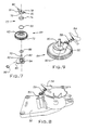
- FIG 9 illustrates the interaction of the stop pin 50 and drive assembly 64 without the gear box 56 shown.
- the spring mechanism 58 biases the stop pin 50 into engagement with the annular portion 62 of the gear 72, thereby engaging the positive stop 80 of the drive assembly 64.
- the throttle trigger 24 operates the cable assembly 32 for engaging and disengaging the stop pin 50 with the positive stop 80 on the drive assembly 64.
- the stop pin 50 is allowed to fully engage into the positive stop 80 on the bearing cage 78 at a top portion of the drive assembly 64, which is located near a bottom portion of the gear box 56.
- the coiled spring mechanism 58 keeps the stop pin 50 in position.
- the present invention also allows the hedge trimmer 10 to be started at a fast idle speed, without pulling the trigger 24 and with no blade movement.
- the fast idle speed for starting is accomplished with the use of a unique carburetor.
- the attached cable 38 pulls the stop pin 50 out of the positive stop 80 in the bearing cage 78, allowing the roller bearing clutch to engage and lock up the drive gear 72 to the drive shaft 70, thereby driving the cutting blade 16.
- the first and second O-rings 86 and 88 are employed as a stabilizing feature and for smooth operation.
Landscapes
- Life Sciences & Earth Sciences (AREA)
- Biodiversity & Conservation Biology (AREA)
- Ecology (AREA)
- Forests & Forestry (AREA)
- Environmental Sciences (AREA)
- Harvester Elements (AREA)
- Braking Arrangements (AREA)
- Portable Power Tools In General (AREA)
Abstract
Description
Claims (22)
- A braking system for a power tool comprising:wherein the stop pin engages the drive assembly via a throttle cable with a coiled return spring.a roller bearing clutch mechanism provided within a drive assembly; anda stop pin which interacts with the roller bearing clutch mechanism to minimize a stopping time of a blade of the power tool,
- The braking system of claim 1, wherein the throttle cable is coupled to a throttle trigger.
- The braking system of claim 2, further comprising a throttle lever to couple the throttle cable and throttle trigger, the throttle lever having a guide slot through which a first end of the throttle cable can travel.
- The braking system of claim 3, wherein the throttle trigger directs the first end of the throttle cable along the guide slot.
- The braking system of claim 1, wherein the throttle cable has a first end coupled to a throttle trigger and a second end coupled to the stop pin.
- The braking system of claim 1, further comprising an anchor to secure the throttle cable to a gear box.
- The braking system of claim 6, wherein the stop pin projects through an aperture in the gear box to engage a positive stop on a top portion of the drive assembly.
- The braking system of claim 1, wherein the roller bearing clutch mechanism includes a bearing cage having a positive stop at a top portion of the bearing cage and a plurality of bearing slots for housing a plurality of roller bearings.
- The braking system of claim 8, wherein the roller bearing clutch mechanism is coupled to a cutting blade drive bushing and positioned within a central portion of a drive gear.
- The braking system of claim 1, wherein a drive shaft of the drive assembly has a counterweight secured thereto.
- The braking system of claim 1, wherein the power tool is a hedge trimmer.
- A braking system for a power tool comprising:a drive assembly having a drive shaft, wherein the drive shaft is supported by bearings on only one end of the drive shaft;a positive stop located at a top portion of the drive assembly; anda stop pin to engage the positive stop to minimize a blade stopping time of the power tool.
- The braking system of claim 12, further comprising a cable coupled to the stop pin and a trigger of the power tool to move the stop pin between an engaged position and a released position.
- The braking system of claim 13, further comprising a cable housing provided over the cable, the cable housing having a first end and a second end, the first end of the cable housing being secured to an end fitting and the second end of the cable housing being secured to an anchor.
- The braking system of claim 14, wherein the end fitting is coupled to a handle portion of the power tool and the anchor is fastened to a top portion of a gear box.
- The braking system of claim 14, further comprising a spring provided over the cable and positioned between the anchor and the stop pin, wherein the spring biases the stop pin towards the drive assembly.
- The braking system of claim 1, wherein the positive stop comprises two arms projecting radially outwardly from a top portion of a bearing cage at opposing sides of the bearing cage.
- The braking system of claim 17, wherein the bearing cage includes a plurality of slots for housing a plurality of roller bearings.
- A braking system for a power tool comprising:a drive assembly, the drive assembly comprising:a drive shaft;a counterweight secured to a bottom portion of the drive shaft; anda positive stop provided at a top portion of the drive shaft; anda stop pin that engages the positive stop to stop a cutting blade of the power tool.
- The braking system of claim 19, wherein the positive stop includes a bearing cage having two arms projecting radially outwardly from a top portion of the bearing cage at opposing sides.
- The braking system of claim 19, wherein the stop pin is secured to a first end portion of a cable assembly.
- The braking system of claim 21, wherein a second end portion of a cable assembly is coupled to a throttle trigger, such that the stop pin is selectively engaged with and released from the positive stop upon activation of the throttle trigger.
Applications Claiming Priority (2)
| Application Number | Priority Date | Filing Date | Title |
|---|---|---|---|
| US10/850,141 US7258205B2 (en) | 2004-05-20 | 2004-05-20 | Blade stop components and roller bearing clutch design for a power tool |
| US850141 | 2004-05-20 |
Publications (2)
| Publication Number | Publication Date |
|---|---|
| EP1597963A2 true EP1597963A2 (en) | 2005-11-23 |
| EP1597963A3 EP1597963A3 (en) | 2006-03-15 |
Family
ID=34943241
Family Applications (1)
| Application Number | Title | Priority Date | Filing Date |
|---|---|---|---|
| EP05445033A Withdrawn EP1597963A3 (en) | 2004-05-20 | 2005-05-18 | Braking device for a power tool |
Country Status (6)
| Country | Link |
|---|---|
| US (1) | US7258205B2 (en) |
| EP (1) | EP1597963A3 (en) |
| JP (1) | JP2005328847A (en) |
| CN (1) | CN1720781A (en) |
| CA (1) | CA2506430C (en) |
| TW (1) | TWI246884B (en) |
Cited By (1)
| Publication number | Priority date | Publication date | Assignee | Title |
|---|---|---|---|---|
| EP1782683A1 (en) * | 2005-11-07 | 2007-05-09 | GARDENA Manufacturing GmbH | Motor-driven garden tool |
Families Citing this family (10)
| Publication number | Priority date | Publication date | Assignee | Title |
|---|---|---|---|---|
| DE202004018885U1 (en) * | 2004-12-07 | 2006-04-13 | Dolmar Gmbh | Brake for a hedge trimmer |
| US8206056B2 (en) | 2006-06-12 | 2012-06-26 | Patriot Barrier Systems, Llc | Barrier system |
| US7942602B2 (en) | 2006-06-12 | 2011-05-17 | Protectus, Llc | Barrier system |
| DE202006009817U1 (en) * | 2006-06-21 | 2007-10-25 | Dolmar Gmbh | brake handle |
| WO2009042644A2 (en) | 2007-09-25 | 2009-04-02 | Perception Raisonnement Action En Medecine | Methods and apparatus for assisting cartilage diagnostic and therapeutic procedures |
| DE102010033978A1 (en) * | 2010-08-11 | 2012-02-16 | Andreas Stihl Ag & Co. Kg | Hand-held implement |
| CN106982653A (en) * | 2017-05-10 | 2017-07-28 | 浙江天泰机械有限公司 | Averruncator self-locking mechanism and averruncator |
| JP6976187B2 (en) * | 2018-02-05 | 2021-12-08 | 株式会社マキタ | Electric tool |
| JP7565220B2 (en) * | 2021-01-05 | 2024-10-10 | 株式会社やまびこ | Shear Mechanism |
| CN117718858A (en) * | 2023-12-22 | 2024-03-19 | 江苏广大鑫盛精密智造有限公司 | Scram device and numerical control vertical grinding center |
Family Cites Families (30)
| Publication number | Priority date | Publication date | Assignee | Title |
|---|---|---|---|---|
| US568987A (en) * | 1896-10-06 | Dry-kiln | ||
| US3361165A (en) * | 1963-11-12 | 1968-01-02 | Outboard Marine Corp | Chain saw |
| US4035994A (en) * | 1975-05-27 | 1977-07-19 | Hoffco, Inc. | Lawn mower blade control apparatus |
| JPS6379446A (en) * | 1986-09-22 | 1988-04-09 | Nec Corp | Telephone set with waking up call service |
| JPH0543249Y2 (en) * | 1986-11-14 | 1993-10-29 | ||
| JPH0335856Y2 (en) * | 1986-11-14 | 1991-07-30 | ||
| DE4005133A1 (en) | 1990-02-17 | 1991-08-22 | Licentia Gmbh | Hand guided electrical tool clutch - has drive wheel with wedge shaped projections to engage drive rollers of simple design and low friction |
| DE4101705C2 (en) * | 1990-09-19 | 1996-12-19 | Atlas Copco Elektrowerkzeuge | Hand-held power tool with a device for quickly stopping the tool |
| JP2840466B2 (en) | 1991-02-01 | 1998-12-24 | 株式会社共立 | Reciprocating saw blade device |
| US5150523A (en) | 1991-07-11 | 1992-09-29 | Ryobi Motor Products Corporation | Deadman switch arrangement for a hedge trimmer |
| US5305528A (en) | 1992-04-17 | 1994-04-26 | Textron Inc. | Power tool braking system |
| JP3338543B2 (en) | 1994-01-20 | 2002-10-28 | 株式会社マキタ | Hedge trimmer |
| DE4418102C2 (en) | 1994-05-24 | 1996-03-21 | Mogatec Moderne Gartentechnik | Motorized hedge trimmers with opposing shear blades |
| DE4421746C2 (en) | 1994-06-22 | 1996-05-15 | Mogatec Moderne Gartentechnik | Motorized hedge trimmers with two-hand safety controls |
| US5531027A (en) | 1994-07-21 | 1996-07-02 | Mcculloch Corporation | Hedge trimmer drive assembly |
| US6129189A (en) | 1995-01-09 | 2000-10-10 | Ker-Train Holdings Ltd. | Spiral type one-way clutch |
| JP3586910B2 (en) * | 1995-01-27 | 2004-11-10 | 日立工機株式会社 | Reciprocating power tool |
| JP3305157B2 (en) * | 1995-05-02 | 2002-07-22 | 株式会社共立 | Hand lever device |
| JP3443483B2 (en) | 1995-06-12 | 2003-09-02 | 株式会社荏原製作所 | Rolling bearing clutch |
| DE19522971A1 (en) | 1995-06-28 | 1997-01-02 | Bosch Gmbh Robert | Hedge trimmer |
| US6170159B1 (en) | 1996-10-29 | 2001-01-09 | Andreas Stihl Ag & Co. | Manually guided implement having a drive motor |
| JP3822333B2 (en) * | 1997-05-14 | 2006-09-20 | 株式会社共立 | Handle device for power working machine |
| JP3601934B2 (en) | 1997-05-16 | 2004-12-15 | 株式会社共立 | Braking device for power work equipment |
| JP3576749B2 (en) | 1997-05-16 | 2004-10-13 | 株式会社共立 | Handle device for power work machine |
| JP3411956B2 (en) | 1997-07-22 | 2003-06-03 | 株式会社共立 | Portable reaper with movable blade braking device |
| JP3567072B2 (en) | 1998-01-16 | 2004-09-15 | 株式会社共立 | Portable reaper with movable blade braking device |
| DE19808118C2 (en) | 1998-02-26 | 2000-04-20 | Stihl Maschf Andreas | Hedge trimmer |
| JP3513040B2 (en) | 1998-12-16 | 2004-03-31 | 株式会社共立 | Portable reaper with movable blade braking device |
| JP3864027B2 (en) * | 2000-02-10 | 2006-12-27 | 株式会社共立 | Intake control mechanism |
| DE10055366B4 (en) | 2000-11-08 | 2011-02-17 | Andreas Stihl Ag & Co | Eccentric drive, especially for a hand-held implement |
-
2004
- 2004-05-20 US US10/850,141 patent/US7258205B2/en not_active Expired - Fee Related
-
2005
- 2005-05-03 TW TW094114221A patent/TWI246884B/en not_active IP Right Cessation
- 2005-05-05 CA CA002506430A patent/CA2506430C/en not_active Expired - Fee Related
- 2005-05-18 CN CNA2005100709451A patent/CN1720781A/en active Pending
- 2005-05-18 EP EP05445033A patent/EP1597963A3/en not_active Withdrawn
- 2005-05-20 JP JP2005147460A patent/JP2005328847A/en active Pending
Cited By (1)
| Publication number | Priority date | Publication date | Assignee | Title |
|---|---|---|---|---|
| EP1782683A1 (en) * | 2005-11-07 | 2007-05-09 | GARDENA Manufacturing GmbH | Motor-driven garden tool |
Also Published As
| Publication number | Publication date |
|---|---|
| JP2005328847A (en) | 2005-12-02 |
| CA2506430C (en) | 2009-02-24 |
| US20050257379A1 (en) | 2005-11-24 |
| TWI246884B (en) | 2006-01-11 |
| CN1720781A (en) | 2006-01-18 |
| CA2506430A1 (en) | 2005-11-20 |
| EP1597963A3 (en) | 2006-03-15 |
| TW200538028A (en) | 2005-12-01 |
| US7258205B2 (en) | 2007-08-21 |
Similar Documents
| Publication | Publication Date | Title |
|---|---|---|
| EP2210467B1 (en) | String head for a trimmer | |
| EP3751978B1 (en) | Trimmer head and trimmer | |
| US11412656B2 (en) | Trimmer head with improved line release feature | |
| US5701967A (en) | Cable control lever apparatus | |
| US10334778B2 (en) | Quick loading trimmer head | |
| US7258205B2 (en) | Blade stop components and roller bearing clutch design for a power tool | |
| US11818979B2 (en) | Grass trimmer | |
| EP2033508B1 (en) | Button type blade brake clutch controls and methods for using same | |
| US20230157205A1 (en) | Control of feed of trimmer line | |
| US5947866A (en) | Braking device for power working machine | |
| EP2227937A1 (en) | Bail-free machine control devices and methods | |
| US11585394B2 (en) | Work machine | |
| US20200269409A1 (en) | Power tool including a light-duty combustion engine | |
| CA2058096A1 (en) | Lawnmower handle assembly | |
| EP2707183B1 (en) | Brake assembly for power-driven hand-held cutting device | |
| JP4451014B2 (en) | Brake actuator for power work equipment | |
| JPH11220923A (en) | Portable reaper | |
| JP4606244B2 (en) | Brush cutter | |
| JP2024157736A (en) | Cable-type manual remote control device | |
| JPH0411812A (en) | Grass-cutter |
Legal Events
| Date | Code | Title | Description |
|---|---|---|---|
| PUAI | Public reference made under article 153(3) epc to a published international application that has entered the european phase |
Free format text: ORIGINAL CODE: 0009012 |
|
| AK | Designated contracting states |
Kind code of ref document: A2 Designated state(s): AT BE BG CH CY CZ DE DK EE ES FI FR GB GR HU IE IS IT LI LT LU MC NL PL PT RO SE SI SK TR |
|
| AX | Request for extension of the european patent |
Extension state: AL BA HR LV MK YU |
|
| RIN1 | Information on inventor provided before grant (corrected) |
Inventor name: HIGGINS, JAMES R., JR. Inventor name: FEAR, TERRY E. Inventor name: BERTI, JEROME L. |
|
| PUAL | Search report despatched |
Free format text: ORIGINAL CODE: 0009013 |
|
| AK | Designated contracting states |
Kind code of ref document: A3 Designated state(s): AT BE BG CH CY CZ DE DK EE ES FI FR GB GR HU IE IS IT LI LT LU MC NL PL PT RO SE SI SK TR |
|
| AX | Request for extension of the european patent |
Extension state: AL BA HR LV MK YU |
|
| 17P | Request for examination filed |
Effective date: 20060915 |
|
| AKX | Designation fees paid |
Designated state(s): AT BE BG CH CY CZ DE DK EE ES FI FR GB GR HU IE IS IT LI LT LU MC NL PL PT RO SE SI SK TR |
|
| 17Q | First examination report despatched |
Effective date: 20061026 |
|
| RAP1 | Party data changed (applicant data changed or rights of an application transferred) |
Owner name: HUSQVARNA OUTDOOR PRODUCTS INC. |
|
| RAP1 | Party data changed (applicant data changed or rights of an application transferred) |
Owner name: HUSQVARNA CONSUMER OUTDOOR PRODUCTS N.A., INC. |
|
| RAP1 | Party data changed (applicant data changed or rights of an application transferred) |
Owner name: HUSQVARNA AB |
|
| STAA | Information on the status of an ep patent application or granted ep patent |
Free format text: STATUS: THE APPLICATION IS DEEMED TO BE WITHDRAWN |
|
| 18D | Application deemed to be withdrawn |
Effective date: 20160412 |