EP1596476A1 - Connector with integral EMI schield - Google Patents
Connector with integral EMI schield Download PDFInfo
- Publication number
- EP1596476A1 EP1596476A1 EP05010344A EP05010344A EP1596476A1 EP 1596476 A1 EP1596476 A1 EP 1596476A1 EP 05010344 A EP05010344 A EP 05010344A EP 05010344 A EP05010344 A EP 05010344A EP 1596476 A1 EP1596476 A1 EP 1596476A1
- Authority
- EP
- European Patent Office
- Prior art keywords
- connector
- electrically conductive
- wings
- hollow end
- conductive member
- Prior art date
- Legal status (The legal status is an assumption and is not a legal conclusion. Google has not performed a legal analysis and makes no representation as to the accuracy of the status listed.)
- Withdrawn
Links
- 230000000149 penetrating effect Effects 0.000 claims 1
- 229910001229 Pot metal Inorganic materials 0.000 abstract description 2
- 238000010276 construction Methods 0.000 abstract description 2
- 230000013011 mating Effects 0.000 description 3
- VLLVVZDKBSYMCG-UHFFFAOYSA-N 1,3,5-trichloro-2-(2-chlorophenyl)benzene Chemical compound ClC1=CC(Cl)=CC(Cl)=C1C1=CC=CC=C1Cl VLLVVZDKBSYMCG-UHFFFAOYSA-N 0.000 description 2
- 239000004020 conductor Substances 0.000 description 2
- 239000002184 metal Substances 0.000 description 2
- 229910052751 metal Inorganic materials 0.000 description 2
- 229910001369 Brass Inorganic materials 0.000 description 1
- 239000010951 brass Substances 0.000 description 1
- 239000012212 insulator Substances 0.000 description 1
- 239000000463 material Substances 0.000 description 1
- 238000012986 modification Methods 0.000 description 1
- 230000004048 modification Effects 0.000 description 1
- 150000003071 polychlorinated biphenyls Chemical class 0.000 description 1
- 229910000679 solder Inorganic materials 0.000 description 1
Images


Classifications
-
- H—ELECTRICITY
- H01—ELECTRIC ELEMENTS
- H01R—ELECTRICALLY-CONDUCTIVE CONNECTIONS; STRUCTURAL ASSOCIATIONS OF A PLURALITY OF MUTUALLY-INSULATED ELECTRICAL CONNECTING ELEMENTS; COUPLING DEVICES; CURRENT COLLECTORS
- H01R24/00—Two-part coupling devices, or either of their cooperating parts, characterised by their overall structure
- H01R24/38—Two-part coupling devices, or either of their cooperating parts, characterised by their overall structure having concentrically or coaxially arranged contacts
- H01R24/40—Two-part coupling devices, or either of their cooperating parts, characterised by their overall structure having concentrically or coaxially arranged contacts specially adapted for high frequency
- H01R24/50—Two-part coupling devices, or either of their cooperating parts, characterised by their overall structure having concentrically or coaxially arranged contacts specially adapted for high frequency mounted on a PCB [Printed Circuit Board]
-
- H—ELECTRICITY
- H01—ELECTRIC ELEMENTS
- H01R—ELECTRICALLY-CONDUCTIVE CONNECTIONS; STRUCTURAL ASSOCIATIONS OF A PLURALITY OF MUTUALLY-INSULATED ELECTRICAL CONNECTING ELEMENTS; COUPLING DEVICES; CURRENT COLLECTORS
- H01R13/00—Details of coupling devices of the kinds covered by groups H01R12/70 or H01R24/00 - H01R33/00
- H01R13/648—Protective earth or shield arrangements on coupling devices, e.g. anti-static shielding
-
- H—ELECTRICITY
- H01—ELECTRIC ELEMENTS
- H01R—ELECTRICALLY-CONDUCTIVE CONNECTIONS; STRUCTURAL ASSOCIATIONS OF A PLURALITY OF MUTUALLY-INSULATED ELECTRICAL CONNECTING ELEMENTS; COUPLING DEVICES; CURRENT COLLECTORS
- H01R12/00—Structural associations of a plurality of mutually-insulated electrical connecting elements, specially adapted for printed circuits, e.g. printed circuit boards [PCB], flat or ribbon cables, or like generally planar structures, e.g. terminal strips, terminal blocks; Coupling devices specially adapted for printed circuits, flat or ribbon cables, or like generally planar structures; Terminals specially adapted for contact with, or insertion into, printed circuits, flat or ribbon cables, or like generally planar structures
- H01R12/70—Coupling devices
- H01R12/7005—Guiding, mounting, polarizing or locking means; Extractors
- H01R12/7011—Locking or fixing a connector to a PCB
- H01R12/707—Soldering or welding
-
- H—ELECTRICITY
- H01—ELECTRIC ELEMENTS
- H01R—ELECTRICALLY-CONDUCTIVE CONNECTIONS; STRUCTURAL ASSOCIATIONS OF A PLURALITY OF MUTUALLY-INSULATED ELECTRICAL CONNECTING ELEMENTS; COUPLING DEVICES; CURRENT COLLECTORS
- H01R2103/00—Two poles
Definitions
- This invention relates to electrical connectors and more particularly to such connectors for receiving a coaxial cable contact. More particularly, it relates to right angle connectors having integral shielding for electromagnetic interference (EMI) for use with printed circuit boards and still more particularly it relates to use connectors suitable for use in high frequency applications.
- EMI electromagnetic interference
- a connector comprising: an electrically conductive member having a longitudinal section and a transverse section, at least a portion of the longitudinal section providing a cylindrical hollow end and the transverse section having four protruding legs for engagement with circuit traces on a printed circuit board, the conductive member additionally being provided with an integral electromagnetic interference (EMI) shield in the form of oppositely disposed wings; an electrically conductive pin positioned with respect to the electrically conductive member, a first part of the electrically conductive pin being substantially centrally located within the hollow end and a second part of the electrically conductive pin extending transversely and substantially parallel to the four legs; and a single-piece electrically insulating body surrounding the electrically conductive member and the electrically conductive pin.
- EMI electromagnetic interference
- the integrally formed EMI shield prevents the escape of electromagnetic interference from the connector during its operational phase, greatly increasing its utility.
- a right-angled connector in accordance with an aspect of the invention comprises a subassembly 10 including an electrically conductive member or ground shell 12 having a longitudinal section 12a and a transverse section 12b.
- the longitudinal section 12a is provided with a longitudinal axis 13 and at least a portion 14 of the member 12 provides a cylindrical, hollow end 16.
- a trough 18 is formed in the member 12 to accommodate an electrically conductive contact pin 18a and at least one leg 19 is provided on member 12 extending in a direction transverse to the longitudinal axis 13.
- the member 12 has four legs 19, as shown in Figs. 2 and 5, which in the final construction will provide the ground connections for the connector, as will be explained hereafter.
- Member 12 can be any electrically conductive material but in a preferred embodiment of the invention it is die cast zinc.
- Member 12 additionally is provided with an integral electromagnetic interference shield in the form of oppositely disposed wings 100, 102, which project from the hollow cylindrical end 16.
- an integral electromagnetic interference shield in the form of oppositely disposed wings 100, 102, which project from the hollow cylindrical end 16.
- Four apertures, 104, 106, 108 and 110 are provided in the wings
- Pin 18a has a first longitudinal part 20 that is substantially centrally located in the hollow end 16 and the trough 18; that is, the first longitudinal part 20 is coaxial with the axis 13, and the pin 18a has a second part 22 that, in the right-angled connector shown, projects in a direction transverse to the longitudinal direction and the axis 13 and which, in the finished connector, will provide the electrical connection to the contact pin.
- Contact pin 18a can be any conductive material but is preferably brass.
- the subassembly 10 is mounted in a suitable mold cavity with the pin 18a held in its appropriate position by tooling, not shown.
- the single-piece, electrically insulating body 32 is then over-molded around the subassembly 10.
- the body 32 can take any appropriate or desired configuration but in a preferred embodiment includes at least two and preferably four spacing feet 34.
- the over-molded material penetrates the openings 104 and 106 to complete a secure bond to the ground shell 12, while the apertures 108 and 110 remain open and can be used for additional mounting accessories such as bolts or screws.
- a tab 40 with a ramp 42 can also be provided to lock in a suitable opening in a mating connector.
- the connector 30 is mounted upon a PCB 50 with the four legs 19 and the second part 22 of pin 18a engaging plated-through holes in the PCB.
- the spacing feet 34 are in contact with one surface of the PCB and serve to provide consistent spacing for the connector 30.
- appropriate solder 52 can be applied to insure adequate electrical connection to the legs 19 and the second part 22 of contact 18a.
- the integrally formed wings 100, 102 provide superior EMI shielding that cannot be accomplished with add-on brackets.
- the apertures 108 and 110 also insure that additional mounting brackets are not required.
Landscapes
- Details Of Connecting Devices For Male And Female Coupling (AREA)
Abstract
A right-angled connector comprises a subassembly (10) including an electrically
conductive member or ground shell (12) having a longitudinal section (12a) and a
transverse section (12b). The longitudinal section (12a) is provided with a longitudinal
axis (13) and at least a portion (14) of the member (12) provides a cylindrical, hollow end
(16). A trough (18) is formed in the member (12) to accommodate an electrically
conductive contact pin (18a) and at least one leg (19) is provided on member (12)
extending in a direction transverse to the longitudinal axis (13). In a preferred
embodiment the member (12) has four legs (19), as shown in Figs. 2 and 5, which in the
final construction will provide the ground connections for the connector. Member (12)
can be die cast zinc. Member (12) additionally is provided with an integral
electromagnetic interference shield in the form of oppositely disposed wings (100, 102),
which project from the hollow cylindrical end 16. Four apertures, (104, 106, 108 and
110) are provided in the wings.
Description
- This application claims priority from Provisional Application No. 60/570,155, filed May 12, 2004.
- This invention relates to electrical connectors and more particularly to such connectors for receiving a coaxial cable contact. More particularly, it relates to right angle connectors having integral shielding for electromagnetic interference (EMI) for use with printed circuit boards and still more particularly it relates to use connectors suitable for use in high frequency applications.
- Electrical connectors, particularly right angled connectors for attachment to printed circuit boards (hereafter, PCB or PCBs) for receiving coaxial cable contacts, for example, for connecting automotive radio antennas, are known. These connectors have worked well in the past; however, they were expensive because of the number of parts they entailed. Such connectors are shown, for example, in U.S. Patent No. 6,386,888. This latter connector comprises a metal bracket, a metal shell, a plastic insulator, a plastic cover and a contact. While this connector works well under normal conditions, test requirements for this connector require that it be plugged into a mating connector on a coaxial cable. This mating connector's cable is then pulled at a defined force through multiple angles. Often, the interface of the cover to the bracket will fail before the required forces are met. It is believed that this failure occurs because of the difficulty in maintaining critical tolerances between the multiple parts.
- Such problems were addressed in a modified connector shown in co-pending patent application S.N. 10/783,566, filed February 20, 2004, and assigned to the assignee of the instant invention.
- While the latter connector solves many of the mechanical problems of the former connector and functions very well, a need exists for such connectors to operate at higher frequencies with a design formulated to reduce or eliminate electromagnetic interference (EMI).
- It is, therefore, an object of the invention to obviate the disadvantages of the prior art.
- It is another object of the invention to enhance electromagnetic shielding on electrical connectors.
- These objects are accomplished, in one aspect of the invention, by the provision of a connector comprising: an electrically conductive member having a longitudinal section and a transverse section, at least a portion of the longitudinal section providing a cylindrical hollow end and the transverse section having four protruding legs for engagement with circuit traces on a printed circuit board, the conductive member additionally being provided with an integral electromagnetic interference (EMI) shield in the form of oppositely disposed wings; an electrically conductive pin positioned with respect to the electrically conductive member, a first part of the electrically conductive pin being substantially centrally located within the hollow end and a second part of the electrically conductive pin extending transversely and substantially parallel to the four legs; and a single-piece electrically insulating body surrounding the electrically conductive member and the electrically conductive pin.
- The integrally formed EMI shield prevents the escape of electromagnetic interference from the connector during its operational phase, greatly increasing its utility.
-
- Fig. 1 is an elevational view of an electrically conductive member or ground shell;
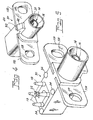
- Fig. 2 is a perspective view of the ground shell of Fig. 1 in a reverse orientation;
- Fig. 3 is a modified, longitudinal sectional view of a completed connector;
- Fig. 4 is a perspective view of a completed connector in a first orientation; and
- Fig. 5 is a perspective view of a completed connector in an inverted orientation.
-
- For a better understanding of the present invention, together with other and further objects, advantages and capabilities thereof, reference is made to the following disclosure and appended claims taken in conjunction with the above-described drawings.
- Referring now to the drawings with greater particularity, there is shown in Fig. 1 a right-angled electrical connector. Specifically, a right-angled connector in accordance with an aspect of the invention comprises a
subassembly 10 including an electrically conductive member orground shell 12 having alongitudinal section 12a and a transverse section 12b. Thelongitudinal section 12a is provided with alongitudinal axis 13 and at least aportion 14 of themember 12 provides a cylindrical,hollow end 16. Atrough 18 is formed in themember 12 to accommodate an electricallyconductive contact pin 18a and at least oneleg 19 is provided onmember 12 extending in a direction transverse to thelongitudinal axis 13. In a preferred embodiment of the invention themember 12 has fourlegs 19, as shown in Figs. 2 and 5, which in the final construction will provide the ground connections for the connector, as will be explained hereafter.Member 12 can be any electrically conductive material but in a preferred embodiment of the invention it is die cast zinc. -
Member 12 additionally is provided with an integral electromagnetic interference shield in the form of oppositely disposedwings cylindrical end 16. Four apertures, 104, 106, 108 and 110 are provided in the wings -
Pin 18a has a firstlongitudinal part 20 that is substantially centrally located in thehollow end 16 and thetrough 18; that is, the firstlongitudinal part 20 is coaxial with theaxis 13, and thepin 18a has asecond part 22 that, in the right-angled connector shown, projects in a direction transverse to the longitudinal direction and theaxis 13 and which, in the finished connector, will provide the electrical connection to the contact pin. Contactpin 18a can be any conductive material but is preferably brass. - To complete a
connector 30, thesubassembly 10 is mounted in a suitable mold cavity with thepin 18a held in its appropriate position by tooling, not shown. - The single-piece, electrically insulating
body 32 is then over-molded around thesubassembly 10. Thebody 32 can take any appropriate or desired configuration but in a preferred embodiment includes at least two and preferably fourspacing feet 34. The over-molded material penetrates theopenings 104 and 106 to complete a secure bond to theground shell 12, while theapertures - A
tab 40 with aramp 42 can also be provided to lock in a suitable opening in a mating connector. - In use the
connector 30 is mounted upon aPCB 50 with the fourlegs 19 and thesecond part 22 ofpin 18a engaging plated-through holes in the PCB. Thespacing feet 34 are in contact with one surface of the PCB and serve to provide consistent spacing for theconnector 30. After mounting theconnector 30 to thePCB 50appropriate solder 52 can be applied to insure adequate electrical connection to thelegs 19 and thesecond part 22 ofcontact 18a. - The integrally formed
wings apertures - While there have been shown and described what are present considered to be the preferred embodiments of the invention, it will be apparent to those skilled in the art that various changes and modifications can be made herein without departing from the scope of the invention as defined by the appended claims.
Claims (5)
- A connector comprising:an electrically conductive member having a longitudinal section and a transverse section, at least a portion of said longitudinal section providing a cylindrical hollow end and said transverse section having four protruding legs for engagement with circuit traces on a printed circuit board, said conductive member additionally being provided with an integral electromagnetic shield in the form of oppositely disposed wings;an electrically conductive pin positioned with respect to said electrically conductive member, a first part of said electrically conductive pin being substantially centrally located within said hollow end and a second part of said electrically conductive pin extending transversely and substantially parallel to said four legs; anda single-piece electrically insulating body surrounding said electrically conductive member and said electrically conductive pin.
- The connector of Claim 1 wherein said wings extend from said cylindrical hollow end and include at least two openings adjacent said hollow end, said single piece electrically insulating body penetrating said at least two openings.
- The connector of Claim 1 wherein said connector is a right-angle connector.
- The connector of Claim 1 wherein said second part of said conductive pin extends beyond a surface of said electrically insulating body.
- The connector of Claim 1 wherein at least one of said wings additionally includes an aperture suitable for mounting said connector upon a structure.
Applications Claiming Priority (4)
| Application Number | Priority Date | Filing Date | Title |
|---|---|---|---|
| US57015504P | 2004-05-12 | 2004-05-12 | |
| US570155P | 2004-05-12 | ||
| US10/913,858 US6932616B1 (en) | 2004-05-12 | 2004-08-07 | Connector with integral EMI shield |
| US913858 | 2004-08-07 |
Publications (1)
| Publication Number | Publication Date |
|---|---|
| EP1596476A1 true EP1596476A1 (en) | 2005-11-16 |
Family
ID=34841248
Family Applications (1)
| Application Number | Title | Priority Date | Filing Date |
|---|---|---|---|
| EP05010344A Withdrawn EP1596476A1 (en) | 2004-05-12 | 2005-05-12 | Connector with integral EMI schield |
Country Status (3)
| Country | Link |
|---|---|
| US (1) | US6932616B1 (en) |
| EP (1) | EP1596476A1 (en) |
| KR (1) | KR20060047763A (en) |
Families Citing this family (6)
| Publication number | Priority date | Publication date | Assignee | Title |
|---|---|---|---|---|
| KR100773838B1 (en) * | 2006-06-09 | 2007-11-06 | 한국단자공업 주식회사 | Horizontal Surface Mount Connectors |
| DE202007017308U1 (en) * | 2007-12-12 | 2008-02-28 | Rosenberger Hochfrequenztechnik Gmbh & Co. Kg | Coaxial connector with a coding housing |
| CN201204343Y (en) * | 2008-05-07 | 2009-03-04 | 富士康(昆山)电脑接插件有限公司 | RF coaxial connector |
| CN202183474U (en) * | 2011-07-01 | 2012-04-04 | 富士康(昆山)电脑接插件有限公司 | Electric connector |
| JP7387407B2 (en) * | 2019-11-27 | 2023-11-28 | 日本航空電子工業株式会社 | connector assembly |
| US12308537B2 (en) * | 2021-12-10 | 2025-05-20 | Ezconn Corporation | Connector |
Citations (3)
| Publication number | Priority date | Publication date | Assignee | Title |
|---|---|---|---|---|
| US5577935A (en) * | 1994-11-03 | 1996-11-26 | Harting Elektronik Gmbh | Coaxial, angular connector for installation on a printed circuit board |
| US5641294A (en) * | 1995-05-31 | 1997-06-24 | Northern Telecom Limited | Backplane assembly including coaxial connectors |
| US6135815A (en) * | 1998-11-20 | 2000-10-24 | Hon Hai Precision Ind. Co., Ltd. | EMI shield having self-aligning device |
Family Cites Families (8)
| Publication number | Priority date | Publication date | Assignee | Title |
|---|---|---|---|---|
| US4502749A (en) * | 1983-12-01 | 1985-03-05 | Amp Incorporated | Coaxial connector for microwave packages |
| US4605269A (en) * | 1984-06-20 | 1986-08-12 | Amp Incorporated | Printed circuit board header having coaxial sockets therein and matable coaxial plug housing |
| US4684200A (en) * | 1985-11-12 | 1987-08-04 | Amp Incorporated | Press fit cable termination for printed circuit boards |
| JPH0542630Y2 (en) * | 1989-03-31 | 1993-10-27 | ||
| US5860812A (en) * | 1997-01-23 | 1999-01-19 | Litton Systems, Inc. | One piece molded RF/microwave coaxial connector |
| US6164977A (en) * | 1998-02-09 | 2000-12-26 | Itt Manufacturing Enterprises, Inc. | Standoff board-mounted coaxial connector |
| US6305947B1 (en) * | 1998-11-19 | 2001-10-23 | Berg Technology, Inc. | Angled coaxial connector module |
| US6822542B2 (en) * | 2001-07-26 | 2004-11-23 | Xytrans, Inc. | Self-adjusted subminiature coaxial connector |
-
2004
- 2004-08-07 US US10/913,858 patent/US6932616B1/en not_active Expired - Fee Related
-
2005
- 2005-05-11 KR KR1020050039259A patent/KR20060047763A/en not_active Withdrawn
- 2005-05-12 EP EP05010344A patent/EP1596476A1/en not_active Withdrawn
Patent Citations (3)
| Publication number | Priority date | Publication date | Assignee | Title |
|---|---|---|---|---|
| US5577935A (en) * | 1994-11-03 | 1996-11-26 | Harting Elektronik Gmbh | Coaxial, angular connector for installation on a printed circuit board |
| US5641294A (en) * | 1995-05-31 | 1997-06-24 | Northern Telecom Limited | Backplane assembly including coaxial connectors |
| US6135815A (en) * | 1998-11-20 | 2000-10-24 | Hon Hai Precision Ind. Co., Ltd. | EMI shield having self-aligning device |
Also Published As
| Publication number | Publication date |
|---|---|
| KR20060047763A (en) | 2006-05-18 |
| US6932616B1 (en) | 2005-08-23 |
Similar Documents
| Publication | Publication Date | Title |
|---|---|---|
| US6575761B1 (en) | Coaxial connector module and method of fabricating same | |
| US7771235B2 (en) | Shielded connector with an inner shield tightly fitted into an outer shield | |
| US6358062B1 (en) | Coaxial connector assembly | |
| US4718854A (en) | Low profile press fit connector | |
| US7946854B2 (en) | Electrical connector assembly having shield member | |
| US6908339B2 (en) | Connector having a simple structure assuring a stable mounting operation | |
| CN109309302B (en) | Coaxial connector | |
| US20040119557A1 (en) | Shielded surface-mount coaxial edge launch connector | |
| US20100255688A1 (en) | Rf connector mounting means | |
| JPH10506223A (en) | Assembly of shielded connector and substrate having plated holes | |
| JP2007525808A (en) | Connector device | |
| US6932616B1 (en) | Connector with integral EMI shield | |
| EP1929846B1 (en) | System and method for shielded coaxial cable attachment | |
| US7491087B2 (en) | Right angled connector | |
| CN101071915B (en) | Shielded electrical connector | |
| CN116073162A (en) | Terminals and Connectors | |
| JP2001297835A (en) | Electrical connector equipment | |
| EP1566862A1 (en) | Right angled connector | |
| CN112470344B (en) | Edge connectors and printed circuit board assemblies | |
| JPH0362467A (en) | Electric connector | |
| EP2828934A1 (en) | Electrical connector having an integrated impedance equalisation element | |
| JP2008059761A (en) | Board shield connector and board shield connector fixing structure | |
| JP2008084561A (en) | Board shield connector connection structure | |
| GB2303258A (en) | Shielded electrical connector | |
| EP2528170B1 (en) | Connector with surface mount signal pin |
Legal Events
| Date | Code | Title | Description |
|---|---|---|---|
| PUAI | Public reference made under article 153(3) epc to a published international application that has entered the european phase |
Free format text: ORIGINAL CODE: 0009012 |
|
| 17P | Request for examination filed |
Effective date: 20050810 |
|
| AK | Designated contracting states |
Kind code of ref document: A1 Designated state(s): AT BE BG CH CY CZ DE DK EE ES FI FR GB GR HU IE IS IT LI LT LU MC NL PL PT RO SE SI SK TR |
|
| AX | Request for extension of the european patent |
Extension state: AL BA HR LV MK YU |
|
| AKX | Designation fees paid |
Designated state(s): DE FR GB |
|
| STAA | Information on the status of an ep patent application or granted ep patent |
Free format text: STATUS: THE APPLICATION IS DEEMED TO BE WITHDRAWN |
|
| 18D | Application deemed to be withdrawn |
Effective date: 20071201 |