EP1596418A1 - Electron gun - Google Patents
Electron gun Download PDFInfo
- Publication number
- EP1596418A1 EP1596418A1 EP04711692A EP04711692A EP1596418A1 EP 1596418 A1 EP1596418 A1 EP 1596418A1 EP 04711692 A EP04711692 A EP 04711692A EP 04711692 A EP04711692 A EP 04711692A EP 1596418 A1 EP1596418 A1 EP 1596418A1
- Authority
- EP
- European Patent Office
- Prior art keywords
- cathode
- electron gun
- electron
- truncated cone
- single crystal
- Prior art date
- Legal status (The legal status is an assumption and is not a legal conclusion. Google has not performed a legal analysis and makes no representation as to the accuracy of the status listed.)
- Granted
Links
Images


Classifications
-
- H—ELECTRICITY
- H01—ELECTRIC ELEMENTS
- H01J—ELECTRIC DISCHARGE TUBES OR DISCHARGE LAMPS
- H01J1/00—Details of electrodes, of magnetic control means, of screens, or of the mounting or spacing thereof, common to two or more basic types of discharge tubes or lamps
- H01J1/02—Main electrodes
- H01J1/13—Solid thermionic cathodes
- H01J1/15—Cathodes heated directly by an electric current
- H01J1/16—Cathodes heated directly by an electric current characterised by the shape
-
- H—ELECTRICITY
- H01—ELECTRIC ELEMENTS
- H01J—ELECTRIC DISCHARGE TUBES OR DISCHARGE LAMPS
- H01J1/00—Details of electrodes, of magnetic control means, of screens, or of the mounting or spacing thereof, common to two or more basic types of discharge tubes or lamps
- H01J1/02—Main electrodes
- H01J1/13—Solid thermionic cathodes
- H01J1/14—Solid thermionic cathodes characterised by the material
- H01J1/146—Solid thermionic cathodes characterised by the material with metals or alloys as an emissive material
-
- H—ELECTRICITY
- H01—ELECTRIC ELEMENTS
- H01J—ELECTRIC DISCHARGE TUBES OR DISCHARGE LAMPS
- H01J1/00—Details of electrodes, of magnetic control means, of screens, or of the mounting or spacing thereof, common to two or more basic types of discharge tubes or lamps
- H01J1/02—Main electrodes
- H01J1/13—Solid thermionic cathodes
- H01J1/20—Cathodes heated indirectly by an electric current; Cathodes heated by electron or ion bombardment
-
- H—ELECTRICITY
- H01—ELECTRIC ELEMENTS
- H01J—ELECTRIC DISCHARGE TUBES OR DISCHARGE LAMPS
- H01J37/00—Discharge tubes with provision for introducing objects or material to be exposed to the discharge, e.g. for the purpose of examination or processing thereof
- H01J37/02—Details
- H01J37/04—Arrangements of electrodes and associated parts for generating or controlling the discharge, e.g. electron-optical arrangement or ion-optical arrangement
- H01J37/06—Electron sources; Electron guns
- H01J37/065—Construction of guns or parts thereof
-
- H—ELECTRICITY
- H01—ELECTRIC ELEMENTS
- H01J—ELECTRIC DISCHARGE TUBES OR DISCHARGE LAMPS
- H01J9/00—Apparatus or processes specially adapted for the manufacture, installation, removal, maintenance of electric discharge tubes, discharge lamps, or parts thereof; Recovery of material from discharge tubes or lamps
- H01J9/02—Manufacture of electrodes or electrode systems
- H01J9/04—Manufacture of electrodes or electrode systems of thermionic cathodes
-
- H—ELECTRICITY
- H01—ELECTRIC ELEMENTS
- H01J—ELECTRIC DISCHARGE TUBES OR DISCHARGE LAMPS
- H01J9/00—Apparatus or processes specially adapted for the manufacture, installation, removal, maintenance of electric discharge tubes, discharge lamps, or parts thereof; Recovery of material from discharge tubes or lamps
- H01J9/02—Manufacture of electrodes or electrode systems
- H01J9/04—Manufacture of electrodes or electrode systems of thermionic cathodes
- H01J9/042—Manufacture, activation of the emissive part
-
- H—ELECTRICITY
- H01—ELECTRIC ELEMENTS
- H01J—ELECTRIC DISCHARGE TUBES OR DISCHARGE LAMPS
- H01J2237/00—Discharge tubes exposing object to beam, e.g. for analysis treatment, etching, imaging
- H01J2237/06—Sources
- H01J2237/063—Electron sources
- H01J2237/06308—Thermionic sources
- H01J2237/06316—Schottky emission
-
- H—ELECTRICITY
- H01—ELECTRIC ELEMENTS
- H01J—ELECTRIC DISCHARGE TUBES OR DISCHARGE LAMPS
- H01J2237/00—Discharge tubes exposing object to beam, e.g. for analysis treatment, etching, imaging
- H01J2237/25—Tubes for localised analysis using electron or ion beams
-
- H—ELECTRICITY
- H01—ELECTRIC ELEMENTS
- H01J—ELECTRIC DISCHARGE TUBES OR DISCHARGE LAMPS
- H01J2237/00—Discharge tubes exposing object to beam, e.g. for analysis treatment, etching, imaging
- H01J2237/26—Electron or ion microscopes
- H01J2237/28—Scanning microscopes
-
- H—ELECTRICITY
- H01—ELECTRIC ELEMENTS
- H01J—ELECTRIC DISCHARGE TUBES OR DISCHARGE LAMPS
- H01J2237/00—Discharge tubes exposing object to beam, e.g. for analysis treatment, etching, imaging
- H01J2237/30—Electron or ion beam tubes for processing objects
- H01J2237/317—Processing objects on a microscale
- H01J2237/3175—Lithography
Definitions
- the present invention relates to an electron gun to be used for an electron beam-applied instrument such as a scanning electron microscope, an Auger electron spectroscope, an electron beam lithography machine or a wafer inspection apparatus, particularly to an electron gun suitable for an electron beam lithography machine.
- an electron beam-applied instrument such as a scanning electron microscope, an Auger electron spectroscope, an electron beam lithography machine or a wafer inspection apparatus, particularly to an electron gun suitable for an electron beam lithography machine.
- an electron gun which employs a cathode said to have a covering layer of zirconium and oxygen formed on a needle electrode made of tungsten single crystal (hereinafter referred to as a ZrO/W electron gun) (D. Tuggle, J. Vac. Sci. Technol. 16, p. 1699 (1979)).
- the ZrO/W electron gun is one wherein a covering layer comprising zirconium and oxygen (hereinafter referred to as a ZrO covering layer) is formed on a needle cathode of tungsten single crystal having an axial orientation being ⁇ 100> orientation.
- a ZrO covering layer a covering layer comprising zirconium and oxygen
- the work function of the (100) crystallographic plane of tungsten single crystal is reduced from 4.5 eV to about 2.8 eV, and only the very small crystallographic facet corresponding to the (100) crystallographic plane formed at the apex of the cathode becomes an electron emission area, whereby an electron beam having a higher brightness than by a conventional thermionic cathode can be obtained, and the electron gun has a characteristic such that it has a long life time. Further, it has characteristics such that it is more stable than a cold field emission electron source and is operable even with a high pressure and easy to use (M. J.
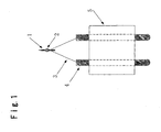
- a tungsten needle cathode 1 having ⁇ 100> orientation which emits an electron beam is fixed by e.g. welding to a predetermined position of a tungsten filament 3 provided on conductive terminals 4 fixed to an insulator 5.
- a zirconium- and oxygen-supply source 2 is formed at a portion of the cathode 1.
- the surface of the cathode 1 is covered with a ZrO covering layer.
- the cathode 1 is Joule heated by the filament 3 and used usually at a temperature of about 1,800 K. Accordingly, the ZrO covering layer on the surface of the cathode 1 will be evaporated. However, from the supply source 2, zirconium and oxygen will diffuse and will be continuously supplied to the surface of the cathode 1, and consequently, the ZrO covering layer will be maintained.
- the ZrO/W electron gun is used so that the forward end of the cathode 1 is disposed between a suppressor 6 and an extractor 7 (see Fig. 2).
- a negative high voltage against the extractor 7 is applied, and to the suppressor 6, a voltage negative by about a few hundreds volt against the cathode 1 is applied, to suppress thermionic electrons from the filament 3.
- the ZrO/W electron gun is operated at an angular intensity of from 0.1 to 0.2 mA/sr for such a reason that the probe current is thereby stable and the energy spread can be suppressed.
- an electron gun is operated at a high angular intensity of about 0.4 mA/sr, since the throughput is thereby of importance.
- operation at a still higher angular intensity is desired, and in some cases, operation at an angular intensity as high as 1.0 mA/sr may be required.
- an electron gun which is an electron gun comprising a cathode 1, a suppressor 6 and an extractor 7, wherein the cathode 1 is made of a rare earth hexaboride, and its apex is disposed between the suppressor 6 and the extractor 7 (JP-A-2001-325910).
- the ZrO/W electron gun has problems such that (1) in high angular intensity operation, an angular intensity at a level of 1.0 mA/sr is the upper limit, and (2) at that time, the extractor voltage to be applied between the cathode and the extractor is as high as at least 4 kV, and the field strength at the apex of chip will be very high at a level of from 0.4 to 1.0 ⁇ 10 9 V/m, whereby frequency of troubles due to arcing will be high.
- the electron gun employing a cathode of a rare earth hexaboride to solve such problems has a drawback that the characteristics will change with the operation time such that the hexaboride will react with the residual oxygen in vacuum and will be consumed by oxidation, whereby the shape of the electron emission portion will be changed (P. R. Davis, J. Vac. Sci. Technol, B4(1), p. 112 (1986), H. Hagiwara, SCANNING ELECTRODE MICROSCOPE, II, p. 473 (1982), SEM Inc.).
- a lanthanum hexaboride thermionic cathode has a drawback such that the electron emission surface tends to be roughened by ion bombardment, and in an extreme case, the shape of the electron emission portion will be changed, whereby ripples will appear in the angle distribution of electron beams, and the uniformity on the electron beam irradiation surface will be deteriorated. Under these circumstances, the life time of an electron gun employing a rare earth hexaboride cathode is at a level of a few months.
- an electron gun comprising a cathode 1, a suppressor 6 and an extractor 7, characterized in that the cathode 1 is made of a rare earth hexaboride, and its apex is disposed between the suppressor 6 and the extractor 7, has a problem that the surplus current is substantial.
- the present invention provides an electron gun provided with a cathode which comprises a single crystal needle (or rod) of tungsten or molybdenum and a supply source to diffuse at least one metal element selected from the group consisting of Groups 2A, 3A and 4A of the periodic table, formed on the needle, wherein an apex of the cathode has a truncated cone shape, and the truncated cone shape portion has a cone angle of from 25° to 95° and a diameter of the top surface of from 5 ⁇ m to 200 ⁇ m.
- the diameter of the top surface of the truncated cone is preferably from 50 ⁇ m to 200 ⁇ m
- the metal element is preferably zirconium or titanium
- the ⁇ 100> orientation of the single crystal constituting the cathode and the direction normal to the top surface are preferably within an angle difference of not more than 2°.
- the present invention provides a process for producing an electron gun provided with a cathode which comprises a single crystal needle (or rod) of tungsten or molybdenum and a supply source to diffuse at least one metal element selected from the group consisting of Groups 2A, 3A and 4A of the periodic table, formed on the needle, which comprises forming an end of a single crystal into a cone shape by mechanical polishing or electrolytic polishing and then removing the forward end of the cone flatly by mechanical polishing or focused gallium ion beam to form a truncated cone shape.
- forming into a truncated cone shape is preferably carried out by a focused gallium ion beam in a xenon difluoride gas atmosphere.
- a specific embodiment of the present invention is one wherein at an end of a rod-shaped cathode 1 of tungsten or molybdenum single crystal having ⁇ 100> orientation, a cone portion 8 is formed by mechanical polishing or electrolytic polishing, and further its apex is polished by a polishing film coated with a diamond abrasive or the apex is cut by means of a focused gallium ion beam device, to provide a flat portion 9.
- the processing time can be shortened by introducing xenon difluoride gas during the processing with a focused gallium ion beam.
- the total angle of the cone portion 8 is from 25° to 95°
- the diameter of the flat portion 9 (or the top surface portion) is from 5 to 200 ⁇ m.
- the normal line to the flat electron emission surface formed at the end of the cathode 1 is preferably within an angle difference of not more than 2°, preferably not more than 0.5°, from the ⁇ 100> orientation.
- the rod of tungsten or molybdenum single crystal having ⁇ 100> orientation will function as a cathode and is provided with a supply source to diffuse at least one metal element selected from the group consisting of Group 2A (such as Be, Mg, Ca, Sr and Ba), Group 3A (such as Sc, Y, lanthanoid elements and actinoid elements) and Group 4A (such as Ti, Zr and Hf) of the periodic table (long-period type).
- Group 2A such as Be, Mg, Ca, Sr and Ba
- Group 3A such as Sc, Y, lanthanoid elements and actinoid elements
- Group 4A such as Ti, Zr and Hf
- zirconium hydride is pulverized and mixed with an organic solvent to form a paste, which is applied to a portion of a cathode, and the cathode is heated in an oxygen atmosphere at a level of 1 ⁇ 10 -6 Torr to thermally decompose ZrH 2 , followed by further oxidation to form a supply source of zirconium and oxygen.
- Such a cathode is disposed between the extractor 7 and the suppressor 6, and a negative high voltage of a few kV is applied to the cathode 1 against the extractor 7.
- a negative voltage of a few hundreds V is applied against the cathode 1, and the at the same time, the cathode 1 is heated at a temperature of from 1,500 to 1,900 K, so that electron emission can be carried out.
- the electron gun of the present invention is operable at a high angular intensity of at least 1 mA/sr and is highly reliable since the total emission current is low at a level of a few tens ⁇ A, and the surplus current is very low. Further, this electron gun is also operable in vacuum of at most 1 ⁇ 10 -8 Torr, and consumption of the cathode is extremely small, and a change in the characteristics is little, even during operation for a long period of time', since tungsten is the base material, and it further has a characteristic such that even if the cathode surface is roughened by ion bombardment, it will immediately be restored to a smooth surface.
- a tungsten filament 3 was fixed by spot welding to conductive terminals 4 fixed to ceramics insulator 5.
- a cone portion 8 having a total angle of 90° was formed by means of a diamond paste and a grinder, and further, the apex of the cone portion was polished with a polishing film coated with a diamond abrasive to form a flat portion 9 having a diameter of 100 ⁇ m.
- This rod was attached to the above filament by spot-welding. This rod functions as a cathode 1.
- Zirconium hydride was pulverized and mixed with isoamyl acetate to form a paste, which was applied to a portion of the cathode 1. After evaporation of isoamyl acetate, the cathode was introduced into an apparatus shown in Fig. 2.
- the apex of the cathode 1 is disposed between the suppressor 6 and an extractor 7.
- the distance between the apex of the cathode 1 and the suppressor 6 is 0.15 mm
- the distance between the suppressor 6 and the extractor 7 is 0.8 mm
- the aperture diameter of the extractor 7 is 0.8 mm
- the aperture diameter of the suppressor 6 is 0.8 mm.
- the filament 3 is connected to a filament heating power source 16 and further connected to a high voltage power source 15, whereby a negative high voltage against the extractor 7, i.e. the extractor voltage V ex , is applied. Further, the suppressor 6 is connected to a bias power source 14, and a further negative voltage i.e. bias voltage Vb, against the cathode 1 and the filament 3, is applied. Thermionic electron emitted from the filament 3 will thereby be shielded. The total emission current It from the electron source is measured by an ammeter 17 disposed between the high voltage power source 15 and an earth. The electron beam (emitted electron beam) 18 emitted from the apex of the cathode 1 will pass through an aperture of the extractor 7 and reach a phosphorous screen 10.
- the interior of the apparatus was brought to an ultrahigh vacuum of 3 ⁇ 10 -10 Torr (4 ⁇ 10 -8 Pa), whereupon an electric current was conducted to the filament 3 to heat the cathode 1 at 1,800 K thereby to thermally decompose ZrH 2 and convert it to metal zirconium. Further, oxygen gas was introduced to bring the interior of the apparatus to be 3 ⁇ 10 -6 Torr (4 ⁇ 10 -4 Pa) thereby to oxidize metal zirconium to form a supply source of zirconium and oxygen.
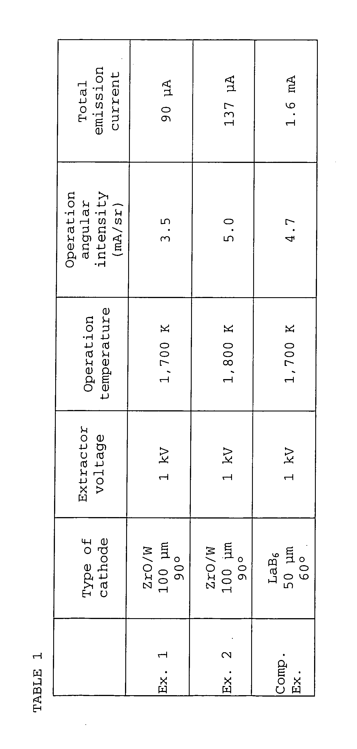
- the electron gun of the present invention is operable at an angular intensity of a level substantially equal to Comparative Example, and the total emission current at that time is smaller by at least one figure than Comparative Example.
- the electron gun of the present invention has high reliability.
- a conventional ZrO/W electron gun has an operation angular intensity of 1 mA/sr at best
- the electron gun of the present invention has a characteristic that at a low extractor voltage of 1 kV, an emission current having a high operation angular intensity at a level of from 3 to 5 mA/sr can be obtained, and thus, it is useful as various electron sources including an electron source for an electron beam lithography machine.
Landscapes
- Engineering & Computer Science (AREA)
- Manufacturing & Machinery (AREA)
- Chemical & Material Sciences (AREA)
- Analytical Chemistry (AREA)
- Electron Sources, Ion Sources (AREA)
- Electron Beam Exposure (AREA)
- Cold Cathode And The Manufacture (AREA)
Abstract
Description
Further, oxygen gas was introduced to bring the interior of the apparatus to be 3×10⁻⁶ Torr (4×10⁻⁴ Pa) thereby to oxidize metal zirconium to form a supply source of zirconium and oxygen.
Claims (6)
- An electron gun provided with a cathode which comprises a single crystal needle of tungsten or molybdenum and a supply source to diffuse at least one metal element selected from the group consisting of Groups 2A, 3A and 4A of the periodic table, formed on the needle, wherein an apex of the cathode has a truncated cone shape, and the truncated cone shape portion has a cone angle of from 25° to 95° and a diameter of the top surface of from 5 µm to 200 µm.
- The electron gun according to Claim 1, wherein the diameter of the top surface of the truncated cone is from 50 µm to 200 µm.
- The electron gun according to Claim 1 or 2, wherein the metal element is zirconium or titanium.
- The electron gun according to Claim 1, 2 or 3, wherein the <100> orientation of the single crystal constituting the cathode and the direction normal to the top surface are within an angle difference of not more than 2°.
- A process for producing an electron gun provided with a cathode which comprises a single crystal needle of tungsten or molybdenum and a supply source to diffuse at least one metal element selected from the group consisting of Groups 2A, 3A and 4A of the periodic table, formed on the needle, which comprises forming an end of a single crystal into a cone shape by mechanical polishing or electrolytic polishing and then removing the forward end of the cone flatly by mechanical polishing or focused gallium ion beam to form a truncated cone shape.
- The process for producing an electron gun according to Claim 5, wherein forming into a truncated cone shape is carried out by a focused gallium ion beam in a xenon difluoride gas atmosphere.
Applications Claiming Priority (3)
| Application Number | Priority Date | Filing Date | Title |
|---|---|---|---|
| JP2003037920 | 2003-02-17 | ||
| JP2003037920 | 2003-02-17 | ||
| PCT/JP2004/001686 WO2004073010A1 (en) | 2003-02-17 | 2004-02-17 | Electron gun |
Publications (3)
| Publication Number | Publication Date |
|---|---|
| EP1596418A1 true EP1596418A1 (en) | 2005-11-16 |
| EP1596418A4 EP1596418A4 (en) | 2010-01-06 |
| EP1596418B1 EP1596418B1 (en) | 2011-07-27 |
Family
ID=32866376
Family Applications (1)
| Application Number | Title | Priority Date | Filing Date |
|---|---|---|---|
| EP04711692A Expired - Lifetime EP1596418B1 (en) | 2003-02-17 | 2004-02-17 | Electron gun |
Country Status (4)
| Country | Link |
|---|---|
| US (1) | US20060145585A1 (en) |
| EP (1) | EP1596418B1 (en) |
| JP (1) | JPWO2004073010A1 (en) |
| WO (1) | WO2004073010A1 (en) |
Cited By (1)
| Publication number | Priority date | Publication date | Assignee | Title |
|---|---|---|---|---|
| EP2242084A4 (en) * | 2008-02-07 | 2011-03-23 | Denki Kagaku Kogyo Kk | METHOD FOR MANUFACTURING ELECTRON SOURCE |
Families Citing this family (4)
| Publication number | Priority date | Publication date | Assignee | Title |
|---|---|---|---|---|
| JP4792404B2 (en) * | 2005-01-14 | 2011-10-12 | 電気化学工業株式会社 | Manufacturing method of electron source |
| WO2008038684A1 (en) | 2006-09-27 | 2008-04-03 | Denki Kagaku Kogyo Kabushiki Kaisha | Electron source |
| JP4782736B2 (en) | 2007-07-12 | 2011-09-28 | 電気化学工業株式会社 | Electron source |
| US8779376B2 (en) * | 2012-01-09 | 2014-07-15 | Fei Company | Determination of emission parameters from field emission sources |
Family Cites Families (14)
| Publication number | Priority date | Publication date | Assignee | Title |
|---|---|---|---|---|
| US3947716A (en) * | 1973-08-27 | 1976-03-30 | The United States Of America As Represented By The Secretary Of The Army | Field emission tip and process for making same |
| JPS5682539A (en) * | 1979-12-07 | 1981-07-06 | Toshiba Corp | Electron gun |
| US4588928A (en) * | 1983-06-15 | 1986-05-13 | At&T Bell Laboratories | Electron emission system |
| JP3582855B2 (en) * | 1994-07-22 | 2004-10-27 | 電気化学工業株式会社 | Thermal field emission cathode and method of manufacturing the same |
| JP3547531B2 (en) * | 1994-08-03 | 2004-07-28 | 株式会社日立製作所 | Electron beam equipment |
| JP3397570B2 (en) * | 1996-04-02 | 2003-04-14 | 電気化学工業株式会社 | Thermal field emission cathode |
| US6190579B1 (en) * | 1997-09-08 | 2001-02-20 | Integrated Thermal Sciences, Inc. | Electron emission materials and components |
| JPH11154479A (en) * | 1997-11-20 | 1999-06-08 | Hitachi Ltd | Secondary electron image detecting method and apparatus, and processing method and apparatus using a focused charged particle beam |
| JP3581254B2 (en) * | 1998-07-02 | 2004-10-27 | 日本電子株式会社 | Thermal field emission electron gun |
| JP2001325910A (en) * | 2000-05-16 | 2001-11-22 | Denki Kagaku Kogyo Kk | Electron gun and how to use it |
| JP4318839B2 (en) * | 2000-05-30 | 2009-08-26 | エスアイアイ・ナノテクノロジー株式会社 | Defect correction device for phase shift mask |
| JP2002216687A (en) * | 2000-11-17 | 2002-08-02 | Denki Kagaku Kogyo Kk | Method for setting operating conditions of thermal field emission cathode and apparatus therefor |
| JP2003324050A (en) * | 2002-04-26 | 2003-11-14 | Advantest Corp | Exposure apparatus and cathode manufacturing method |
| US6838683B1 (en) * | 2003-06-18 | 2005-01-04 | Intel Corporation | Focused ion beam microlathe |
-
2004
- 2004-02-17 WO PCT/JP2004/001686 patent/WO2004073010A1/en not_active Ceased
- 2004-02-17 JP JP2005505025A patent/JPWO2004073010A1/en active Pending
- 2004-02-17 EP EP04711692A patent/EP1596418B1/en not_active Expired - Lifetime
- 2004-02-17 US US10/545,808 patent/US20060145585A1/en not_active Abandoned
Cited By (1)
| Publication number | Priority date | Publication date | Assignee | Title |
|---|---|---|---|---|
| EP2242084A4 (en) * | 2008-02-07 | 2011-03-23 | Denki Kagaku Kogyo Kk | METHOD FOR MANUFACTURING ELECTRON SOURCE |
Also Published As
| Publication number | Publication date |
|---|---|
| US20060145585A1 (en) | 2006-07-06 |
| EP1596418A4 (en) | 2010-01-06 |
| WO2004073010A1 (en) | 2004-08-26 |
| JPWO2004073010A1 (en) | 2006-06-01 |
| EP1596418B1 (en) | 2011-07-27 |
Similar Documents
| Publication | Publication Date | Title |
|---|---|---|
| JP4971342B2 (en) | Electron source | |
| US6903499B2 (en) | Electron gun and a method for using the same | |
| EP1592040B1 (en) | Electron source | |
| US8593048B2 (en) | Electron source having a tungsten single crystal electrode | |
| EP2242084B1 (en) | Method of manufacturing an electron source | |
| US7722425B2 (en) | Electron source manufacturing method | |
| EP1596418B1 (en) | Electron gun | |
| WO2007148507A1 (en) | Electron source | |
| JP2005276720A (en) | Field emission electron gun and electron beam application apparatus using the same | |
| WO2011040326A1 (en) | Rod for electron source, electron source, and electronic appliance | |
| JP2008004411A (en) | Electron source | |
| EP3996126B1 (en) | Emitter, electron gun comprising the emitter, electronic device comprising the electron gun, and method for producing the emitter | |
| JP4368501B2 (en) | Usage of electron emission cathode | |
| JP2006032195A (en) | Electron emission source | |
| JP4874758B2 (en) | Electron source |
Legal Events
| Date | Code | Title | Description |
|---|---|---|---|
| PUAI | Public reference made under article 153(3) epc to a published international application that has entered the european phase |
Free format text: ORIGINAL CODE: 0009012 |
|
| 17P | Request for examination filed |
Effective date: 20050810 |
|
| AK | Designated contracting states |
Kind code of ref document: A1 Designated state(s): AT BE BG CH CY CZ DE DK EE ES FI FR GB GR HU IE IT LI LU MC NL PT RO SE SI SK TR |
|
| AX | Request for extension of the european patent |
Extension state: AL LT LV MK |
|
| DAX | Request for extension of the european patent (deleted) | ||
| RBV | Designated contracting states (corrected) |
Designated state(s): DE GB NL |
|
| A4 | Supplementary search report drawn up and despatched |
Effective date: 20091209 |
|
| RIC1 | Information provided on ipc code assigned before grant |
Ipc: H01J 37/073 20060101AFI20040831BHEP Ipc: H01J 37/063 20060101ALI20091203BHEP Ipc: H01J 37/075 20060101ALI20091203BHEP Ipc: H01J 9/04 20060101ALI20091203BHEP Ipc: H01J 1/16 20060101ALI20091203BHEP |
|
| 17Q | First examination report despatched |
Effective date: 20100222 |
|
| GRAP | Despatch of communication of intention to grant a patent |
Free format text: ORIGINAL CODE: EPIDOSNIGR1 |
|
| GRAS | Grant fee paid |
Free format text: ORIGINAL CODE: EPIDOSNIGR3 |
|
| GRAA | (expected) grant |
Free format text: ORIGINAL CODE: 0009210 |
|
| AK | Designated contracting states |
Kind code of ref document: B1 Designated state(s): DE GB NL |
|
| REG | Reference to a national code |
Ref country code: GB Ref legal event code: FG4D |
|
| REG | Reference to a national code |
Ref country code: DE Ref legal event code: R096 Ref document number: 602004033629 Country of ref document: DE Effective date: 20110922 |
|
| REG | Reference to a national code |
Ref country code: NL Ref legal event code: T3 |
|
| PLBE | No opposition filed within time limit |
Free format text: ORIGINAL CODE: 0009261 |
|
| STAA | Information on the status of an ep patent application or granted ep patent |
Free format text: STATUS: NO OPPOSITION FILED WITHIN TIME LIMIT |
|
| 26N | No opposition filed |
Effective date: 20120502 |
|
| REG | Reference to a national code |
Ref country code: DE Ref legal event code: R097 Ref document number: 602004033629 Country of ref document: DE Effective date: 20120502 |
|
| PGFP | Annual fee paid to national office [announced via postgrant information from national office to epo] |
Ref country code: GB Payment date: 20211230 Year of fee payment: 19 |
|
| PGFP | Annual fee paid to national office [announced via postgrant information from national office to epo] |
Ref country code: DE Payment date: 20211230 Year of fee payment: 19 |
|
| PGFP | Annual fee paid to national office [announced via postgrant information from national office to epo] |
Ref country code: NL Payment date: 20220118 Year of fee payment: 19 |
|
| P01 | Opt-out of the competence of the unified patent court (upc) registered |
Effective date: 20230512 |
|
| REG | Reference to a national code |
Ref country code: DE Ref legal event code: R119 Ref document number: 602004033629 Country of ref document: DE |
|
| REG | Reference to a national code |
Ref country code: NL Ref legal event code: MM Effective date: 20230301 |
|
| GBPC | Gb: european patent ceased through non-payment of renewal fee |
Effective date: 20230217 |
|
| PG25 | Lapsed in a contracting state [announced via postgrant information from national office to epo] |
Ref country code: NL Free format text: LAPSE BECAUSE OF NON-PAYMENT OF DUE FEES Effective date: 20230301 |
|
| PG25 | Lapsed in a contracting state [announced via postgrant information from national office to epo] |
Ref country code: GB Free format text: LAPSE BECAUSE OF NON-PAYMENT OF DUE FEES Effective date: 20230217 |
|
| PG25 | Lapsed in a contracting state [announced via postgrant information from national office to epo] |
Ref country code: GB Free format text: LAPSE BECAUSE OF NON-PAYMENT OF DUE FEES Effective date: 20230217 Ref country code: DE Free format text: LAPSE BECAUSE OF NON-PAYMENT OF DUE FEES Effective date: 20230901 |