EP1596354A2 - Plasma display apparatus and image processing method thereof - Google Patents
Plasma display apparatus and image processing method thereof Download PDFInfo
- Publication number
- EP1596354A2 EP1596354A2 EP05010180A EP05010180A EP1596354A2 EP 1596354 A2 EP1596354 A2 EP 1596354A2 EP 05010180 A EP05010180 A EP 05010180A EP 05010180 A EP05010180 A EP 05010180A EP 1596354 A2 EP1596354 A2 EP 1596354A2
- Authority
- EP
- European Patent Office
- Prior art keywords
- values
- gray level
- brightness
- real
- sub
- Prior art date
- Legal status (The legal status is an assumption and is not a legal conclusion. Google has not performed a legal analysis and makes no representation as to the accuracy of the status listed.)
- Withdrawn
Links
Images




Classifications
-
- G—PHYSICS
- G09—EDUCATION; CRYPTOGRAPHY; DISPLAY; ADVERTISING; SEALS
- G09G—ARRANGEMENTS OR CIRCUITS FOR CONTROL OF INDICATING DEVICES USING STATIC MEANS TO PRESENT VARIABLE INFORMATION
- G09G3/00—Control arrangements or circuits, of interest only in connection with visual indicators other than cathode-ray tubes
- G09G3/20—Control arrangements or circuits, of interest only in connection with visual indicators other than cathode-ray tubes for presentation of an assembly of a number of characters, e.g. a page, by composing the assembly by combination of individual elements arranged in a matrix no fixed position being assigned to or needed to be assigned to the individual characters or partial characters
- G09G3/22—Control arrangements or circuits, of interest only in connection with visual indicators other than cathode-ray tubes for presentation of an assembly of a number of characters, e.g. a page, by composing the assembly by combination of individual elements arranged in a matrix no fixed position being assigned to or needed to be assigned to the individual characters or partial characters using controlled light sources
- G09G3/28—Control arrangements or circuits, of interest only in connection with visual indicators other than cathode-ray tubes for presentation of an assembly of a number of characters, e.g. a page, by composing the assembly by combination of individual elements arranged in a matrix no fixed position being assigned to or needed to be assigned to the individual characters or partial characters using controlled light sources using luminous gas-discharge panels, e.g. plasma panels
- G09G3/288—Control arrangements or circuits, of interest only in connection with visual indicators other than cathode-ray tubes for presentation of an assembly of a number of characters, e.g. a page, by composing the assembly by combination of individual elements arranged in a matrix no fixed position being assigned to or needed to be assigned to the individual characters or partial characters using controlled light sources using luminous gas-discharge panels, e.g. plasma panels using AC panels
- G09G3/296—Driving circuits for producing the waveforms applied to the driving electrodes
-
- G—PHYSICS
- G09—EDUCATION; CRYPTOGRAPHY; DISPLAY; ADVERTISING; SEALS
- G09G—ARRANGEMENTS OR CIRCUITS FOR CONTROL OF INDICATING DEVICES USING STATIC MEANS TO PRESENT VARIABLE INFORMATION
- G09G3/00—Control arrangements or circuits, of interest only in connection with visual indicators other than cathode-ray tubes
- G09G3/20—Control arrangements or circuits, of interest only in connection with visual indicators other than cathode-ray tubes for presentation of an assembly of a number of characters, e.g. a page, by composing the assembly by combination of individual elements arranged in a matrix no fixed position being assigned to or needed to be assigned to the individual characters or partial characters
- G09G3/2007—Display of intermediate tones
- G09G3/2059—Display of intermediate tones using error diffusion
-
- G—PHYSICS
- G09—EDUCATION; CRYPTOGRAPHY; DISPLAY; ADVERTISING; SEALS
- G09G—ARRANGEMENTS OR CIRCUITS FOR CONTROL OF INDICATING DEVICES USING STATIC MEANS TO PRESENT VARIABLE INFORMATION
- G09G3/00—Control arrangements or circuits, of interest only in connection with visual indicators other than cathode-ray tubes
- G09G3/20—Control arrangements or circuits, of interest only in connection with visual indicators other than cathode-ray tubes for presentation of an assembly of a number of characters, e.g. a page, by composing the assembly by combination of individual elements arranged in a matrix no fixed position being assigned to or needed to be assigned to the individual characters or partial characters
- G09G3/2007—Display of intermediate tones
- G09G3/2059—Display of intermediate tones using error diffusion
- G09G3/2062—Display of intermediate tones using error diffusion using error diffusion in time
-
- G—PHYSICS
- G09—EDUCATION; CRYPTOGRAPHY; DISPLAY; ADVERTISING; SEALS
- G09G—ARRANGEMENTS OR CIRCUITS FOR CONTROL OF INDICATING DEVICES USING STATIC MEANS TO PRESENT VARIABLE INFORMATION
- G09G3/00—Control arrangements or circuits, of interest only in connection with visual indicators other than cathode-ray tubes
- G09G3/20—Control arrangements or circuits, of interest only in connection with visual indicators other than cathode-ray tubes for presentation of an assembly of a number of characters, e.g. a page, by composing the assembly by combination of individual elements arranged in a matrix no fixed position being assigned to or needed to be assigned to the individual characters or partial characters
- G09G3/22—Control arrangements or circuits, of interest only in connection with visual indicators other than cathode-ray tubes for presentation of an assembly of a number of characters, e.g. a page, by composing the assembly by combination of individual elements arranged in a matrix no fixed position being assigned to or needed to be assigned to the individual characters or partial characters using controlled light sources
- G09G3/28—Control arrangements or circuits, of interest only in connection with visual indicators other than cathode-ray tubes for presentation of an assembly of a number of characters, e.g. a page, by composing the assembly by combination of individual elements arranged in a matrix no fixed position being assigned to or needed to be assigned to the individual characters or partial characters using controlled light sources using luminous gas-discharge panels, e.g. plasma panels
- G09G3/2803—Display of gradations
-
- G—PHYSICS
- G09—EDUCATION; CRYPTOGRAPHY; DISPLAY; ADVERTISING; SEALS
- G09G—ARRANGEMENTS OR CIRCUITS FOR CONTROL OF INDICATING DEVICES USING STATIC MEANS TO PRESENT VARIABLE INFORMATION
- G09G2320/00—Control of display operating conditions
- G09G2320/02—Improving the quality of display appearance
- G09G2320/0271—Adjustment of the gradation levels within the range of the gradation scale, e.g. by redistribution or clipping
-
- G—PHYSICS
- G09—EDUCATION; CRYPTOGRAPHY; DISPLAY; ADVERTISING; SEALS
- G09G—ARRANGEMENTS OR CIRCUITS FOR CONTROL OF INDICATING DEVICES USING STATIC MEANS TO PRESENT VARIABLE INFORMATION
- G09G2320/00—Control of display operating conditions
- G09G2320/02—Improving the quality of display appearance
- G09G2320/0271—Adjustment of the gradation levels within the range of the gradation scale, e.g. by redistribution or clipping
- G09G2320/0276—Adjustment of the gradation levels within the range of the gradation scale, e.g. by redistribution or clipping for the purpose of adaptation to the characteristics of a display device, i.e. gamma correction
Definitions
- Each of the eight sub-fields SF1 to SF8 is subdivided into a reset period, an address period and a sustain period.
- n 0, 1,2,3,4,5,6,7
- FIG. 2 is a graph showing comparison results of brightness characteristics between a PDP and a CRT.
- the CRT and LCD represent a desired gray level by controlling displayed light in analog mode according to an input video signal.
- the PDP represents a gray level by modulating the number of light pulses using a matrix array of a discharge cell that can be turned on or off. It thus has linear brightness characteristics.
- PWM pulse width modulation
- the brightness of the PDP varies linearly against the number of pulses.
- noise is generated when the gray level is represented in a low gray level region. Accordingly, in order to solve this problem, input video data undergo inverse gamma correction in the conventional PDP. That is, after a reference brightness value such as the CRT brightness curve of FIG. 2 is set, a gamma curve data LUT storage unit in which gamma curve data look-up table (LUT) corresponding to reference brightness values are stored is provided, and input gray level values undergo inverse gamma correction.
- LUT gamma curve data look-up table
- the gamma curve data stored in the gamma curve look-up table fulfill the following equation assuming that n is a predetermined gray level value, Re al ( n ) is a real brightness value depending upon the gray level value, and Re( n ) is a reference brightness value depending upon the gray level value.
- Gamma curve data Re f ( n ) - Re al ( n ) Re al ( n +1) - Re al ( n ) + Re al ( n )
- the halftone unit extracts n th and (n+m) th gray level values having the real brightness values, and generates gray levels of n + 1, ..., n + m-1 being intermediate values of the gray levels.
- the real brightness values depending upon the gray level values are the brightness values that are directly measured using a brightness measurement apparatus when brightness values depending upon the gray level values are displayed on a panel.
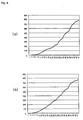
- FIGS. 5(a) and 5(b) are graphs showing the relationship between real brightness values and gray level values according to an embodiment of the present invention.
- FIG. 7 is a block diagram for explaining generation of gray levels according to an embodiment of the present invention.
- Equation 2 the parameters used in Equation 2 can be defined as follows.
- n indicates a predetermined gray level value.
- Real ( n ) indicates the real brightness value depending upon the gray level value n.
- a gray level representation apparatus includes a gamma curve data LUT storage unit in which gamma curve data are stored as LUT.
- the apparatus employs data of the gamma curve data LUT upon inverse gamma correction.
- the linearity of a gray level can be improved by generating gamma curve data using real brightness values.
Landscapes
- Engineering & Computer Science (AREA)
- Physics & Mathematics (AREA)
- Computer Hardware Design (AREA)
- General Physics & Mathematics (AREA)
- Theoretical Computer Science (AREA)
- Plasma & Fusion (AREA)
- Power Engineering (AREA)
- Control Of Indicators Other Than Cathode Ray Tubes (AREA)
Abstract
Description
To achieve the above object, according to an aspect of the present invention, there is provided a plasma display apparatus, including an inverse gamma correction unit that subjects externally input data to inverse gamma correction using a gamma curve look-up table in which reference brightness value data depending upon gray level values and data corresponding to real brightness values displayed on a panel are stored; and a halftone unit that subjects the inverse gamma corrected data to dithering or error diffusion, thereby increasing the representability of gray levels.
Claims (12)
- A plasma display apparatus, comprising:an inverse gamma correction unit performing inverse gamma correction using a gamma curve look-up table in which reference brightness value data depending upon gray level values and data corresponding to real brightness values displayed on a panel are stored; anda halftone unit for dithering or performing error diffusion on the inverse gamma corrected data to increase the representability of gray levels.
- The plasma display apparatus as claimed in claim 1, wherein the gamma curve data stored in the gamma curve look-up table satisfy the following equation assuming that n is a predetermined gray level value, Real(n) is a real brightness value depending upon the gray level value, and Ref(n) is a reference brightness value depending upon the gray level value.
- The plasma display apparatus as claimed in claim 1, wherein the halftone unit extracts nth and (n+m)th gray level values having the real brightness values, and generates gray levels of n + 1, ..., n + m-1 which is intermediate values of the gray levels.
- The plasma display apparatus as claimed in claim 1, wherein the real brightness values depending upon the gray level values are the brightness values that are directly measured using a brightness measurement apparatus when brightness values depending upon the gray level values are displayed on a panel.
- The plasma display apparatus as claimed in claim 1, wherein the real brightness values depending upon the gray level values are found by measuring a brightness value of a reset period and an address period corresponding to each sub-field, and by measuring a brightness value corresponding to one pulse of a sustain period corresponding to each sub-field.
- The plasma display apparatus as claimed in claim 5, wherein assuming that each sub-field is SFM(a), the brightness value of the reset period and the address period corresponding to each sub-field is RA(a), the brightness value corresponding to one pulse of the sustain pulse corresponding to each sub-field is S(a), and the sustain weight depending upon a difference of the sustain period of each sub-field is Sη(a), the real brightness value fulfills the following equation:
- An image processing method of a plasma display apparatus, comprising the steps of:performing inverse gamma correction using a gamma curve look-up table in which reference brightness value data depending upon gray level values and data corresponding to real brightness values displayed on a panel are stored; andperforming halftoning by dithering or error diffusion on the inverse gamma corrected data
- The image processing method as claimed in claim 7, wherein the gamma curve data stored in the gamma curve look-up table fulfill the following equation assuming that n is a predetermined gray level value, Real(n) is a real brightness value depending upon the gray level value, and Ref(n) is a reference brightness value depending upon the gray level value.
- The image processing method as claimed in claim 7, wherein the step of subjecting the inverse gamma corrected data to dithering or error diffusion includes the steps of:extracting nth and (n + m)th gray level values having the real brightness values; andgenerating gray levels of n + 1, ..., n + m-1 being intermediate values of the gray levels using the extracted nth and (n + m)th gray level values.
- The image processing method as claimed in claim 7, wherein the real brightness values depending upon the gray level values are the brightness values that are directly measured using a brightness measurement apparatus when brightness values depending upon the gray level values are displayed on a panel.
- The image processing method as claimed in claim 7, wherein the real brightness values depending upon the gray level values are found by measuring a brightness value of a reset period and an address period corresponding to each sub-field, measuring a brightness value corresponding to one pulse of a sustain period corresponding to each sub-field, and then using the values measured in the reset period, the address period and the sustain period for obtaining the real brightness values.
- The image processing method as claimed in claim 11, wherein assuming that each sub-field is SFM(a), the brightness value of the reset period and the address period corresponding to each sub-field is RA(a), the brightness value corresponding to one pulse of the sustain pulse corresponding to each sub-field is S(a), and the sustain weight depending upon a difference of the sustain period of each sub-field is Sη(a), the real brightness value fulfills the following equation:
Applications Claiming Priority (2)
| Application Number | Priority Date | Filing Date | Title |
|---|---|---|---|
| KR1020040034468A KR100996412B1 (en) | 2004-05-14 | 2004-05-14 | Gray scale display device and method of plasma display panel |
| KR2004034468 | 2004-05-14 |
Publications (2)
| Publication Number | Publication Date |
|---|---|
| EP1596354A2 true EP1596354A2 (en) | 2005-11-16 |
| EP1596354A3 EP1596354A3 (en) | 2007-06-20 |
Family
ID=34936366
Family Applications (1)
| Application Number | Title | Priority Date | Filing Date |
|---|---|---|---|
| EP05010180A Withdrawn EP1596354A3 (en) | 2004-05-14 | 2005-05-11 | Plasma display apparatus and image processing method thereof |
Country Status (3)
| Country | Link |
|---|---|
| US (1) | US7696958B2 (en) |
| EP (1) | EP1596354A3 (en) |
| KR (1) | KR100996412B1 (en) |
Families Citing this family (4)
| Publication number | Priority date | Publication date | Assignee | Title |
|---|---|---|---|---|
| KR100625476B1 (en) * | 2005-05-30 | 2006-09-20 | 엘지전자 주식회사 | Plasma Display Device and Image Processing Method |
| KR100898299B1 (en) * | 2007-11-14 | 2009-05-18 | 삼성에스디아이 주식회사 | Plasma display device and driving method thereof |
| CN108877657B (en) | 2018-07-25 | 2020-06-30 | 京东方科技集团股份有限公司 | Brightness compensation method and device, and display device |
| CN112397024B (en) * | 2020-11-23 | 2021-06-22 | 新相微电子(上海)有限公司 | Intelligent dynamic compensation system and method of OLED |
Family Cites Families (24)
| Publication number | Priority date | Publication date | Assignee | Title |
|---|---|---|---|---|
| JP3107260B2 (en) * | 1993-03-02 | 2000-11-06 | 株式会社富士通ゼネラル | Color display |
| WO2000043979A1 (en) * | 1999-01-22 | 2000-07-27 | Matsushita Electric Industrial Co., Ltd. | Apparatus and method for making a gray scale display with subframes |
| JP3630584B2 (en) * | 1999-04-28 | 2005-03-16 | パイオニア株式会社 | Display panel drive method |
| US6639605B2 (en) * | 1999-12-17 | 2003-10-28 | Koninklijke Philips Electronics N.V. | Method of and unit for displaying an image in sub-fields |
| US6674446B2 (en) * | 1999-12-17 | 2004-01-06 | Koninilijke Philips Electronics N.V. | Method of and unit for displaying an image in sub-fields |
| KR100659348B1 (en) | 2000-09-04 | 2006-12-19 | 오리온피디피주식회사 | Gamma Correction Device and Method in Plasma Display Panel |
| EP1206120A1 (en) * | 2000-11-10 | 2002-05-15 | GRETAG IMAGING Trading AG | Reducing artifacts in reproduced images |
| JP2004519708A (en) * | 2001-02-23 | 2004-07-02 | コーニンクレッカ フィリップス エレクトロニクス エヌ ヴィ | Method and unit for displaying an image in a subfield |
| KR100438918B1 (en) * | 2001-12-08 | 2004-07-03 | 엘지전자 주식회사 | Method and apparatus for driving plasma display panel |
| JP2003177697A (en) | 2001-12-12 | 2003-06-27 | Mitsubishi Electric Corp | Video display device |
| EP1353315A1 (en) * | 2002-04-11 | 2003-10-15 | Thomson Licensing S.A. | Method and apparatus for processing video pictures to improve grey scale resolution of a display device |
| US7164396B2 (en) * | 2002-05-22 | 2007-01-16 | Lg Electronics Inc. | Method and apparatus of driving plasma display panel |
| TW582006B (en) * | 2002-06-14 | 2004-04-01 | Chunghwa Picture Tubes Ltd | Brightness correction apparatus and method for plasma display |
| KR100477972B1 (en) * | 2003-01-15 | 2005-03-23 | 삼성에스디아이 주식회사 | Plasma display panel and gray display method thereof |
| US7327898B2 (en) * | 2003-07-01 | 2008-02-05 | Xerox Corporation | Reducing boundary effects for images with screen patterns |
| KR100497235B1 (en) * | 2003-10-01 | 2005-06-23 | 삼성에스디아이 주식회사 | A driving apparatus of plasma panel and a method for displaying pictures on plasma display panel |
| KR100599747B1 (en) * | 2003-10-16 | 2006-07-12 | 삼성에스디아이 주식회사 | Driving Device of Plasma Display Panel and Its Gradient Expression Method |
| KR100578836B1 (en) * | 2003-11-19 | 2006-05-11 | 삼성에스디아이 주식회사 | Driving apparatus for plasma display panel and image processing method for plasma display panel |
| KR100499102B1 (en) * | 2003-12-15 | 2005-07-01 | 엘지전자 주식회사 | Apparatus and Method of Driving Plasma Display Panel |
| KR20050096082A (en) * | 2004-03-29 | 2005-10-05 | 엘지전자 주식회사 | Image processing apparatus for plasma display panel |
| KR100561342B1 (en) * | 2004-06-15 | 2006-03-17 | 삼성에스디아이 주식회사 | Driving apparatus for plasma display panel and image processing method thereof |
| KR20050120204A (en) * | 2004-06-18 | 2005-12-22 | 삼성에스디아이 주식회사 | Driving method of plasma display panel |
| KR20050121923A (en) * | 2004-06-23 | 2005-12-28 | 삼성에스디아이 주식회사 | Plasma display device and method for displaying pictures on plasma display device |
| JP4255467B2 (en) * | 2005-10-26 | 2009-04-15 | シャープ株式会社 | Digital gamma correction circuit and digital gamma correction method |
-
2004
- 2004-05-14 KR KR1020040034468A patent/KR100996412B1/en not_active Expired - Fee Related
-
2005
- 2005-05-11 EP EP05010180A patent/EP1596354A3/en not_active Withdrawn
- 2005-05-12 US US11/127,186 patent/US7696958B2/en not_active Expired - Fee Related
Also Published As
| Publication number | Publication date |
|---|---|
| EP1596354A3 (en) | 2007-06-20 |
| KR100996412B1 (en) | 2010-11-24 |
| US7696958B2 (en) | 2010-04-13 |
| KR20050109000A (en) | 2005-11-17 |
| US20050253786A1 (en) | 2005-11-17 |
Similar Documents
| Publication | Publication Date | Title |
|---|---|---|
| US7025252B2 (en) | Apparatus and method for driving plasma display panel to enhance display of gray scale and color | |
| CN102209986A (en) | Plasma display device and plasma display panel driving method | |
| EP1615199A2 (en) | Plasma display apparatus and image processing method thereof | |
| US7696958B2 (en) | Plasma display apparatus and image processing method thereof | |
| EP1583066A2 (en) | Plasma display apparatus and image processing method thereof | |
| EP1587053A2 (en) | Plasma display apparatus and image processing method thereof | |
| US7609283B2 (en) | Plasma display apparatus and image processing method thereof | |
| KR100607247B1 (en) | Image processing apparatus of the plasma display panel | |
| JP2817597B2 (en) | Display device drive circuit | |
| KR100667555B1 (en) | Image Processing Method of Plasma Display Panel | |
| US20060125723A1 (en) | Plasma display apparatus and driving method thereof | |
| KR100594649B1 (en) | Image Processing Method of Plasma Display Panel | |
| KR100738816B1 (en) | Image processing apparatus and image processing method of plasma display panel | |
| KR100612516B1 (en) | Image processing apparatus and image processing method of plasma display panel | |
| KR100579933B1 (en) | Image processing apparatus and image processing method of plasma display panel | |
| KR100658353B1 (en) | Image processing apparatus and image processing method of plasma display panel | |
| KR100658359B1 (en) | Image processing apparatus and image processing method of plasma display panel | |
| KR100551122B1 (en) | Driving device and driving method of plasma display panel | |
| KR100518297B1 (en) | Plasma Display Panel | |
| KR100705841B1 (en) | Plasma Display Device and Image Processing Method | |
| KR100493973B1 (en) | Method and Apparatus of Driving Plasma Display Panel | |
| KR100612517B1 (en) | Image processing apparatus and image processing method of plasma display panel | |
| KR100625549B1 (en) | Image Processing Method of Plasma Display Panel | |
| KR20060091208A (en) | Image processing apparatus and image processing method of plasma display panel | |
| KR20060004393A (en) | Image Processing Method of Plasma Display Panel |
Legal Events
| Date | Code | Title | Description |
|---|---|---|---|
| PUAI | Public reference made under article 153(3) epc to a published international application that has entered the european phase |
Free format text: ORIGINAL CODE: 0009012 |
|
| 17P | Request for examination filed |
Effective date: 20050511 |
|
| AK | Designated contracting states |
Kind code of ref document: A2 Designated state(s): AT BE BG CH CY CZ DE DK EE ES FI FR GB GR HU IE IS IT LI LT LU MC NL PL PT RO SE SI SK TR |
|
| AX | Request for extension of the european patent |
Extension state: AL BA HR LV MK YU |
|
| PUAL | Search report despatched |
Free format text: ORIGINAL CODE: 0009013 |
|
| AK | Designated contracting states |
Kind code of ref document: A3 Designated state(s): AT BE BG CH CY CZ DE DK EE ES FI FR GB GR HU IE IS IT LI LT LU MC NL PL PT RO SE SI SK TR |
|
| AX | Request for extension of the european patent |
Extension state: AL BA HR LV MK YU |
|
| AKX | Designation fees paid |
Designated state(s): DE FR GB NL |
|
| 17Q | First examination report despatched |
Effective date: 20080331 |
|
| STAA | Information on the status of an ep patent application or granted ep patent |
Free format text: STATUS: THE APPLICATION IS DEEMED TO BE WITHDRAWN |
|
| 18D | Application deemed to be withdrawn |
Effective date: 20091201 |