EP1596322A2 - Driving lane recognizer and driving lane recognizing method - Google Patents
Driving lane recognizer and driving lane recognizing method Download PDFInfo
- Publication number
- EP1596322A2 EP1596322A2 EP05010160A EP05010160A EP1596322A2 EP 1596322 A2 EP1596322 A2 EP 1596322A2 EP 05010160 A EP05010160 A EP 05010160A EP 05010160 A EP05010160 A EP 05010160A EP 1596322 A2 EP1596322 A2 EP 1596322A2
- Authority
- EP
- European Patent Office
- Prior art keywords
- lane
- driving
- lane marker
- line
- region
- Prior art date
- Legal status (The legal status is an assumption and is not a legal conclusion. Google has not performed a legal analysis and makes no representation as to the accuracy of the status listed.)
- Granted
Links
Images


Classifications
-
- G—PHYSICS
- G06—COMPUTING OR CALCULATING; COUNTING
- G06V—IMAGE OR VIDEO RECOGNITION OR UNDERSTANDING
- G06V20/00—Scenes; Scene-specific elements
- G06V20/50—Context or environment of the image
- G06V20/56—Context or environment of the image exterior to a vehicle by using sensors mounted on the vehicle
- G06V20/588—Recognition of the road, e.g. of lane markings; Recognition of the vehicle driving pattern in relation to the road
-
- G—PHYSICS
- G06—COMPUTING OR CALCULATING; COUNTING
- G06V—IMAGE OR VIDEO RECOGNITION OR UNDERSTANDING
- G06V10/00—Arrangements for image or video recognition or understanding
- G06V10/20—Image preprocessing
- G06V10/22—Image preprocessing by selection of a specific region containing or referencing a pattern; Locating or processing of specific regions to guide the detection or recognition
-
- G—PHYSICS
- G06—COMPUTING OR CALCULATING; COUNTING
- G06V—IMAGE OR VIDEO RECOGNITION OR UNDERSTANDING
- G06V10/00—Arrangements for image or video recognition or understanding
- G06V10/40—Extraction of image or video features
- G06V10/44—Local feature extraction by analysis of parts of the pattern, e.g. by detecting edges, contours, loops, corners, strokes or intersections; Connectivity analysis, e.g. of connected components
Definitions
- the present invention relates to a driving lane recognizer and a driving lane recognizing method for detecting a lane marker on a vehicle's driving road.
- One of the conventionally known apparatus for detecting a lane marker on a driving road is a driving lane detector for vehicle arranged to take an image of a state of a driving road with a video camera set in the front part of the vehicle and to detect a type of a white line on the driving road on the basis of the image, as described in Japanese Patent Application Laid-Open No. 2000-14595.
- This is a device that detects candidate points for a white line by image processing of the image and that determines whether the white line is a solid line or a dashed line, based on the white line candidate point data and past detection rate data of white line candidate points.
- this device needs to store the past detection rate data of white line candidate points in order to determine the type of the white line, and is thus unable to determine the type of the white line without the past detection rate data of white line candidate points.
- it takes a considerable time for determining the type of the white line if the vehicle is traveling at low speed.
- An object of the present invention is therefore to provide a driving lane recognizer and a driving lane recognizing method capable of determining a type of a lane marker without use of past data.
- a driving lane recognizing apparatus is a driving lane recognizer for detecting a lane marker provided on a driving road on the basis of an image taken of the driving road, the driving lane recognizer comprising: lane marker detector that detects a length of a lane marker in each of a near region and a far region adjacently set along a vehicle traveling direction in the image; and determining element that determines a type of the lane marker on the basis of the length of the lane marker in the near region and the length of the lane marker in the far region, which are detected by the lane marker detector.
- a driving lane recognizing method is a driving lane recognizing method for detecting a lane marker provided on a driving road on the basis of an image taken of the driving road, the driving lane recognizer comprising: lane marker detecting step for detecting a length of a lane marker in each of a near region and a far region adjacently set along a vehicle traveling direction in the image; and determining step for determining a type of the lane marker on the basis of the length of the lane marker in the near region and the length of the lane marker in the far region, which are detected by the lane marker detecting step.
- the driving lane recognizer is configured to detect the length of the lane marker in each of the near region and the far region of the image and to determine the type of the lane marker on the basis of the lengths of the lane marker thus detected, whereby the driving lane recognizer is able to determine the type of the lane marker on the basis of one image and thus to determine the type of the lane marker without use of past detection data.
- the driving lane recognizer according to the present invention is also characterized in that when the lengths of the lane marker detected in both of the near region and the far region are longer than a predetermined value, the determining element determines that the lane marker is a solid line.
- the driving lane recognizing method according to the present invention is also characterized in that when the lengths of the lane marker detected in both of the near region and the far region are longer than a predetermined value, the determining step determines that the lane marker is a solid line.
- the driving lane recognizer is also characterized in that when the length of the lane marker detected in one of the near region and the far region is longer than the predetermined value and when the length of the lane marker detected in the other is not more than the predetermined value, the determining element determines that the lane marker is a dashed line.
- the driving lane recognizing method is also characterized in that when the length of the lane marker detected in one of the near region and the far region is longer than the predetermined value and when the length of the lane marker detected in the other is not more than the predetermined value, the determining step determines that the lane marker is a dashed line.
- the driving lane recognizer compares the lengths of the lane marker in the near region and in the far region with the predetermined value, whereby the driving lane recognizer is able to accurately determine whether the lane marker is a solid line or a dashed line.
- the driving lane recognizer according to the present invention is also characterized in that lengths of the near region and the far region in the vehicle traveling direction are set to be longer than a line-drawn part of a dashed line and shorter than a lineless part of the dashed line.
- the length of the line-drawn part and the length of the lineless part of the dashed line mean lengths in the vehicle traveling direction.
- the driving lane recognizing method according to the present invention is also characterized in that lengths of the near region and the far region in the vehicle traveling direction are set to be longer than a line-drawn part of a dashed line and shorter than a lineless part of the dashed line.
- the driving lane recognizer according to the present invention is also characterized in that lengths of the near region and the far region in the vehicle traveling direction are set to be longer than a lineless part of a dashed line and shorter than a sum of a line-drawn part and a lineless part of the dashed line.
- the length of the lineless part of the dashed line and the length of the sum of the line-drawn part and the lineless part of the dashed line mean lengths in the vehicle traveling direction.
- the driving lane recognizing method according to the present invention is also characterized in that lengths of the near region and the far region in the vehicle traveling direction are set to be longer than a lineless part of a dashed line and shorter than a sum of a line-drawn part and a lineless part of the dashed line.
- the image tends to be in a state in which only a lineless part is present in one of the near region and the far region and in which only a line-drawn part is present in the other. For this reason, the lengths of the white line detected in the near region and in the far region tend to be above or below the predetermined value, which improves the detection accuracy of the dashed line.
- the present invention enables the apparatus to make a determination on the type of the lane marker without use of past data.
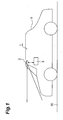
- Fig. 1 is a schematic diagram to show a configuration of a driving lane recognizer according to an embodiment of the present invention.
- the driving lane recognizer 1 is an apparatus mounted on a vehicle 5, which detects a white line as a lane marker on a driving road 20 on which the vehicle 5 is traveling, and which recognizes a driving lane on the basis of the detection result.
- the "lane marker” means a border line of a lane among road signs, and embraces white lines, and lines of other colors, e.g., yellow lines.
- the driving lane recognizer 1 is provided with an image taking unit 2.
- the image taking unit 2 functions as an imaging means for imaging surrounding circumstances around the vehicle and is installed, for example, so as to take a forward image ahead the vehicle 5.
- This image taking unit 2 can be, for example, a C-MOS camera.
- the image taking unit 2 is connected to ECU (Electronic Control Unit) 3.
- ECU 3 controls the entire system and is composed, for example, of a CPU, a ROM, a RAM, an input signal circuit, an output signal circuit, a power supply circuit, and so on.
- ECU 3 is a unit that receives an image from the image taking unit 2, performs image processing of the image, and detects a white line provided on the vehicle's driving road.
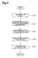
- Fig. 2 is a flowchart showing the operation of the driving lane recognizer according to the present embodiment.
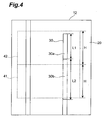
- Figs. 3 and 4 are imagery drawings of images in the control process of Fig. 2. The control process in Fig. 2 is executed by ECU 3.
- an image is retrieved, as shown at S10 in Fig. 2.
- This retrieval of the image is carried out in such a manner that ECU 3 receives an image taken by the image taking unit 2 and reads the image signal in the form of digital image data.
- the image 11 is displayed so that the driving road 20 is vertically directed, as shown in Fig. 3.
- the driving road 20 is provided with white line 30.
- the ECU moves to S12 in Fig. 2 to perform a white line detecting process in each of near region 41 and far region 42.
- the near region 41 and the far region 42 are set as respective, individual windows so that they are adjacent to each other along the vehicle traveling direction in one image 11.
- the white line detecting process is a process of detecting a length of white line 30 in each of the near region 41 and the far region 42, based on image processing of the image 11.
- This white line detecting process is done, for example, by successively carrying out image processing consisting of extraction of edge points, coordinate transformation, detection of white line, and detection of white line length.
- the extraction of edge points is a process of extracting edge points in the image 11 by use of a differential filter or the like.
- the coordinate transformation is a process of performing such a coordinate transformation as to transform the image 11 to an image as viewed from immediately above the driving road 20. For example, it is implemented by setting the width direction of the driving road 20 as an X-axis and the vehicle traveling direction on the driving road 20 as a Y-axis.
- This coordinate transformation process transforms the image 11 to a transformed image 12 as a plan view from immediately above the driving road 20, as shown in Fig. 4.
- the white line detection is a process of subjecting the extracted edge points to straight line approximation to detect white line 30 in each of the near region 41 and the far region 42.
- a technique of the straight line approximation is, for example, a method of calculating the number of edge points on a straight line and outputting a straight line with the largest number of points as a result of the straight line approximation, like the Hough transform.
- the white line length detection is a process of detecting the length of white line 30 in each of the near region 41 and the far region 42.
- This white line length detection can be implemented, for example, by taking a ratio of the number of edge points on the straight line detected by the white line detection, to the number of points of the straight line on the screen, i.e., by determining the ratio of the length of the white line to the length of the straight line on the screen.
- the result of the white line detection process is that the length of white line 30 in the near region 41 is zero and that the length of white line 30 in the far region 42 is L1.
- the white line type determining process is a process of determining a type of white line 30, by which the type of white line 30 is determined based on the length of white line 30 in the near region 41 and the length of white line 30 in the far region 42, e.g., whether white line 30 is a solid line or a dashed line is determined.
- This white line type determining process is carried out, for example, as described below.
- the white line 30 is a solid line.
- the predetermined value set on this occasion is, for example, a length equivalent to a half length (L1/2) of a line-drawn part 30a. It is 4 m on highways and 3 m on general roads.
- This predetermined value is preferably set based on geographical information of a navigation system. Specifically, a type of a road on which the vehicle is currently traveling is detected based on the geographical information and the predetermined value is set according to the type of the road. This enables the appropriate process of determining the type of the white line.
- the predetermined value may also be set as follows: the length of white line 30 is detected by a road type determining process described later, whether the vehicle is traveling on a highway or on a general road is determined based on the length detected, and the predetermined value is set using the result of the determination. It is also possible to use an identical predetermined value without identification of either a highway or a general road.
- the white line type determining process in the case where the length of white line 30 detected in either one of the near region 41 and the far region 42 is longer than the predetermined value and where the length of white line 30 detected in the other is not more than the predetermined value, it is determined that the white line 30 is a dashed line.
- the white line type determining process in the case where the lengths of white line 30 detected in both of the near region 41 and the far region 42 are not more than the predetermined value, it is determined, for example, that there is no detection result of a type of white line 30. In this case, it is preferable to use a detection result prior to the current detection, e.g., a previous detection result, as a current detection result.
- This white line type determining process at S 14 is not limited to the above-described determination technique, and can be any other determination technique as long as it can determine whether white line 30 is a dashed line or a solid line.
- whether white line 30 is a solid line or a dashed line may be determined based on a sum of the lengths of white line 30 detected in the near region 41 and in the far region 42. In this case, it is determined that the white line is a solid line when the sum of the lengths of white line 30 is not less than a predetermined length, and that the white line is a dashed line when the sum of the lengths of white line 30 is shorter than the predetermined length.
- the lengths H in the vehicle traveling direction of the near region 41 and the far region 42 be set to be longer than a line-drawn part 30a of the dashed line and shorter than a lineless part 30b of the dashed line. It is also preferable that the lengths H in the vehicle traveling direction of the near region 41 and the far region 42 be set to be longer than a lineless part 30b of the dashed line and shorter than the length of the sum (L1+L2) of a line-drawn part 30a and a lineless part 30b of the dashed line.
- the length of the line-drawn part 30a of the dashed line, the length of the lineless part 30b of the dashed line, and the length of the sum of the line-drawn part 30a and the lineless part 30b of the dashed line mean lengths in the vehicle traveling direction.
- This road type determining process is a process of determining a type of driving road 20 on the basis of the lengths of white line 30 detected by the white line detecting process at S12. For example, supposing the white line 30 is a dashed line, when the length of the line-drawn part 30a in the dashed line is a length equivalent to 6 m, the driving road 20 is determined to be a general road; when the length of the line-drawn part 30a is a length equivalent to 8 m, the driving road 20 is determined to be a highway.
- the accuracy of the determination on the type of the road may be improved by comparing the result of the type of the road determined by the road type determining process with the result of the type of the road detected by the navigation system.
- control unit moves to S 18 in Fig. 2 to perform a driving lane recognition process, based on the white line detection result, and then completes the control process.
- the control unit calculates values indicating the shape of the road, for example, such as the width and the radius R of curvature of the driving lane.
- the driving lane can be recognized more accurately by switching parameter values used in the calculation of the values indicating the shape of the road, according to the type of the road detected at S16.
- the driving lane recognizer 1 of the present embodiment is configured to set the near region 41 and the far region 42 in the image, to detect the length of white line 30 in each of these near region 41 and far region 42, and to determine the type of white line 30 on the basis of the lengths of white line 30 thus detected, whereby the driving lane recognizer is able to determine the type of white line 30 on the basis of one image and to determine the type of white line 30 without use of past detection data or the like. Since the driving lane recognizer is able to determine the type of white line 30 on the basis of image data of one frame and does not have to retrieve a plurality of image data, it is able to quickly perform the determination process.
- the driving lane recognizer determines the type of white line 30 by comparing the lengths of white line 30 detected in the near region 41 and in the far region 42 with the predetermined value, whereby it is able to accurately determine whether white line 30 is a solid line or a dashed line.
- the driving lane recognizer 1 of the present embodiment is able to recognize that the traveling part is an interim common use part (a portion used for opposite driving on a highway).
- the driving lane recognizer is able to recognize that the vehicle is traveling on the left driving lane.
- the recognizer is able to recognize that the vehicle is traveling on the right driving lane.
- the driving lane recognizer 1 of the present embodiment is effectively used as a part of a vehicle operation support system.
- a traveling position of the vehicle relative to driving road 20 can be detected on the basis of the result of detection of white line 30 by the driving lane recognizer 1 of the present embodiment. Therefore, when the traveling position of the vehicle deviates either to the left or to the right, a steering control is carried out so as to correct it to implement a steering support, whereby it is feasible to secure safe vehicle driving.
- the present embodiment described the case where in the white line detection process at S 12 the white line length detection was carried out after the coordinate transformation of the image 11, but the white line length detection may be carried out before the coordinate transformation. It is also possible to carry out the white line length detection without coordinate transformation.
- the driving lane recognizer may also be configured to detect the lengths of a line of any other color than white line 30 and to determine the type of the line, as long as the line is a lane marker.
Landscapes
- Engineering & Computer Science (AREA)
- Physics & Mathematics (AREA)
- General Physics & Mathematics (AREA)
- Multimedia (AREA)
- Theoretical Computer Science (AREA)
- Computer Vision & Pattern Recognition (AREA)
- Traffic Control Systems (AREA)
- Image Analysis (AREA)
- Length Measuring Devices By Optical Means (AREA)
- Image Processing (AREA)
Abstract
Description
a driving lane recognizing method according to the present invention is a driving lane recognizing method for detecting a lane marker provided on a driving road on the basis of an image taken of the driving road, the driving lane recognizer comprising: lane marker detecting step for detecting a length of a lane marker in each of a near region and a far region adjacently set along a vehicle traveling direction in the image; and determining step for determining a type of the lane marker on the basis of the length of the lane marker in the near region and the length of the lane marker in the far region, which are detected by the lane marker detecting step.
The driving lane recognizing method according to the present invention is also characterized in that when the lengths of the lane marker detected in both of the near region and the far region are longer than a predetermined value, the determining step determines that the lane marker is a solid line.
The driving lane recognizing method according to the present invention is also characterized in that when the length of the lane marker detected in one of the near region and the far region is longer than the predetermined value and when the length of the lane marker detected in the other is not more than the predetermined value, the determining step determines that the lane marker is a dashed line.
The driving lane recognizing method according to the present invention is also characterized in that lengths of the near region and the far region in the vehicle traveling direction are set to be longer than a line-drawn part of a dashed line and shorter than a lineless part of the dashed line.
The driving lane recognizing method according to the present invention is also characterized in that lengths of the near region and the far region in the vehicle traveling direction are set to be longer than a lineless part of a dashed line and shorter than a sum of a line-drawn part and a lineless part of the dashed line.
Claims (13)
- A driving lane recognizer for detecting a lane marker provided on a driving road on the basis of an image taken of the driving road, the driving lane recognizer comprising:lane marker detector that detects a length of a lane marker in each of a near region and a far region adjacently set along a vehicle traveling direction in the image; anddetermining element that determines a type of the lane marker on the basis of the length of the lane marker in the near region and the length of the lane marker in the far region, which are detected by the lane marker detector.
- The driving lane recognizer according to Claim 1, wherein when the lengths of the lane marker detected in both of the near region and the far region are longer than a predetermined value, the determining element determines that the lane marker is a solid line.
- The driving lane recognizer according to Claim 1 or 2, wherein when the length of the lane marker detected in one of the near region and the far region is longer than the predetermined value and when the length of the lane marker detected in the other is not more than the predetermined value, the determining element determines that the lane marker is a dashed line.
- The driving lane recognizer according to any one of Claims 1 to 3, wherein lengths of the near region and the far region in the vehicle traveling direction are set to be longer than a line-drawn part of a dashed line and shorter than a lineless part of the dashed line.
- The driving lane recognizer according to any one of Claims 1 to 3, wherein lengths of the near region and the far region in the vehicle traveling direction are set to be longer than a lineless part of a dashed line and shorter than a sum of a line-drawn part and a lineless part of the dashed line.
- The driving lane recognizer according to any one of Claims 1 to 5, which is an apparatus to be mounted on a vehicle, and which comprises image taking means for taking an image of the driving road.
- The driving lane recognizer according to Claim 6, wherein the image taking means is a camera for taking a forward image ahead the vehicle.
- The driving lane recognizer according to any one of Claims 1 to 7, wherein the lane marker detector and the determining element are an electronic control unit.
- A driving lane recognizing method for detecting a lane marker provided on a driving road on the basis of an image taken of the driving road, the driving lane recognizing method comprising:lane marker detecting step for detecting a length of a lane marker in each of a near region and a far region adjacently set along a vehicle traveling direction in the image; anddetermining step for determining a type of the lane marker on the basis of the length of the lane marker in the near region and the length of the lane marker in the far region, which are detected by the lane marker detecting step.
- The driving lane recognizing method according to Claim 9, wherein when the lengths of the lane marker detected in both of the near region and the far region are longer than a predetermined value, the determining step determines that the lane marker is a solid line.
- The driving lane recognizing method according to Claim 9 or 10, wherein when the length of the lane marker detected in one of the near region and the far region is longer than the predetermined value and when the length of the lane marker detected in the other is not more than the predetermined value, the determining step determines that the lane marker is a dashed line.
- The driving lane recognizing method according to any one of Claims 9 to 11, wherein lengths of the near region and the far region in the vehicle traveling direction are set to be longer than a line-drawn part of a dashed line and shorter than a lineless part of the dashed line.
- The driving lane recognizing method according to any one of Claims 9 to 11, wherein lengths of the near region and the far region in the vehicle traveling direction are set to be longer than a lineless part of a dashed line and shorter than a sum of a line-drawn part and a lineless part of the dashed line.
Applications Claiming Priority (2)
| Application Number | Priority Date | Filing Date | Title |
|---|---|---|---|
| JP2004141536 | 2004-05-11 | ||
| JP2004141536A JP3945494B2 (en) | 2004-05-11 | 2004-05-11 | Travel lane recognition device |
Publications (3)
| Publication Number | Publication Date |
|---|---|
| EP1596322A2 true EP1596322A2 (en) | 2005-11-16 |
| EP1596322A3 EP1596322A3 (en) | 2010-11-17 |
| EP1596322B1 EP1596322B1 (en) | 2019-11-06 |
Family
ID=34936354
Family Applications (1)
| Application Number | Title | Priority Date | Filing Date |
|---|---|---|---|
| EP05010160.9A Expired - Lifetime EP1596322B1 (en) | 2004-05-11 | 2005-05-10 | Driving lane recognizer and driving lane recognizing method |
Country Status (3)
| Country | Link |
|---|---|
| US (1) | US7403219B2 (en) |
| EP (1) | EP1596322B1 (en) |
| JP (1) | JP3945494B2 (en) |
Cited By (5)
| Publication number | Priority date | Publication date | Assignee | Title |
|---|---|---|---|---|
| EP2253936A1 (en) * | 2009-05-21 | 2010-11-24 | Clarion Co., Ltd. | Current position determining device and current position determining nethod |
| EP2065835A3 (en) * | 2007-11-29 | 2012-07-18 | Aisin AW Co., Ltd. | Image recognition apparatus and image recognition program |
| EP2629243A1 (en) * | 2012-02-15 | 2013-08-21 | Delphi Technologies, Inc. | Method for detecting and tracking lane markings |
| CN104272363A (en) * | 2012-04-27 | 2015-01-07 | 株式会社电装 | Boundary-line-detecting device, boundary-line-deviation-detecting device, and boundary-line-detecting program |
| CN106464843A (en) * | 2014-09-05 | 2017-02-22 | 堺显示器制品株式会社 | Image generation apparatus, image generation method, and computer program |
Families Citing this family (16)
| Publication number | Priority date | Publication date | Assignee | Title |
|---|---|---|---|---|
| DE102004040143A1 (en) * | 2004-08-19 | 2006-02-23 | Robert Bosch Gmbh | Method and device for driver information |
| DE102005044979A1 (en) * | 2005-09-20 | 2007-03-22 | Adc Automotive Distance Control Systems Gmbh | Method for detecting lane markings |
| JP4923647B2 (en) * | 2006-03-17 | 2012-04-25 | 株式会社デンソー | Driving support image display device and program |
| KR101075615B1 (en) * | 2006-07-06 | 2011-10-21 | 포항공과대학교 산학협력단 | Apparatus and method for generating a auxiliary information of moving vehicles for driver |
| JP4775658B2 (en) * | 2006-12-27 | 2011-09-21 | アイシン・エィ・ダブリュ株式会社 | Feature recognition device, vehicle position recognition device, navigation device, feature recognition method |
| JP5014237B2 (en) * | 2008-04-23 | 2012-08-29 | 本田技研工業株式会社 | Lane marker recognition device, vehicle, and lane marker recognition program |
| JP4525812B2 (en) * | 2008-08-08 | 2010-08-18 | 株式会社デンソー | Exposure setting device, exposure setting program, and image processing device |
| JP5664152B2 (en) * | 2009-12-25 | 2015-02-04 | 株式会社リコー | Imaging device, in-vehicle imaging system, and object identification device |
| JP5983729B2 (en) * | 2012-03-05 | 2016-09-06 | 日産自動車株式会社 | White line detection device, white line detection filter device, and white line detection method |
| KR101500082B1 (en) * | 2013-06-10 | 2015-03-18 | 현대자동차주식회사 | Apparatus and method for recognizing driving lane |
| DE102013217860A1 (en) * | 2013-09-06 | 2015-03-12 | Robert Bosch Gmbh | Method and device for determining a road course of a roadway of a vehicle |
| CN106347363A (en) * | 2016-10-12 | 2017-01-25 | 深圳市元征科技股份有限公司 | Lane keeping method and lane keeping device |
| US11008039B2 (en) * | 2017-04-12 | 2021-05-18 | Toyota Jidosha Kabushiki Kaisha | Lane change assist apparatus for vehicle |
| EP3576008B1 (en) | 2018-05-30 | 2023-12-27 | Aptiv Technologies Limited | Image based lane marking classification |
| CN115049990B (en) * | 2020-04-16 | 2026-03-20 | 阿里巴巴集团控股有限公司 | Data processing methods, equipment and storage media |
| US11551459B1 (en) * | 2022-06-27 | 2023-01-10 | Plusai, Inc. | Ambiguous lane detection event miner |
Citations (4)
| Publication number | Priority date | Publication date | Assignee | Title |
|---|---|---|---|---|
| JPH04184609A (en) | 1990-11-20 | 1992-07-01 | Ricoh Co Ltd | Signal transfer device |
| JPH05108147A (en) | 1991-10-14 | 1993-04-30 | Mazda Motor Corp | Travelling path recognizing device of moving vehicle |
| JPH08320997A (en) | 1995-05-24 | 1996-12-03 | Nissan Motor Co Ltd | Vehicle lane recognition device, obstacle detection device, road departure notification device |
| JP2000014595A (en) | 1998-06-26 | 2000-01-18 | Nikken Corp | Deodorizing device |
Family Cites Families (11)
| Publication number | Priority date | Publication date | Assignee | Title |
|---|---|---|---|---|
| US4766421A (en) * | 1986-02-19 | 1988-08-23 | Auto-Sense, Ltd. | Object detection apparatus employing electro-optics |
| JPH04184603A (en) * | 1990-11-20 | 1992-07-01 | Toyota Motor Corp | Guide line detecting device |
| US6577334B1 (en) * | 1998-02-18 | 2003-06-10 | Kabushikikaisha Equos Research | Vehicle control |
| JP2001014595A (en) | 1999-06-29 | 2001-01-19 | Mitsubishi Motors Corp | Traveling lane detection device for vehicles |
| US6882287B2 (en) * | 2001-07-31 | 2005-04-19 | Donnelly Corporation | Automotive lane change aid |
| JP2003317106A (en) * | 2002-04-26 | 2003-11-07 | Nissan Motor Co Ltd | Roadway recognition device |
| DE50309206D1 (en) * | 2002-06-11 | 2008-04-03 | Bosch Gmbh Robert | METHOD AND DEVICE FOR DRIVER INFORMATION BZW. FOR RESPONSE TO LEAVING THE ROAD TRACK |
| DE10333670B4 (en) * | 2003-07-18 | 2019-07-04 | Iav Gmbh Ingenieurgesellschaft Auto Und Verkehr | Method for determining the road course from image data |
| JP2005215985A (en) * | 2004-01-29 | 2005-08-11 | Fujitsu Ltd | Traveling lane determination program, recording medium therefor, traveling lane determination device, and traveling lane determination method |
| DE102005018697A1 (en) * | 2004-06-02 | 2005-12-29 | Daimlerchrysler Ag | Method and device for warning a driver in the event of leaving the traffic lane |
| US7050908B1 (en) * | 2005-03-22 | 2006-05-23 | Delphi Technologies, Inc. | Lane marker projection method for a motor vehicle vision system |
-
2004
- 2004-05-11 JP JP2004141536A patent/JP3945494B2/en not_active Expired - Fee Related
-
2005
- 2005-05-03 US US11/119,762 patent/US7403219B2/en active Active
- 2005-05-10 EP EP05010160.9A patent/EP1596322B1/en not_active Expired - Lifetime
Patent Citations (4)
| Publication number | Priority date | Publication date | Assignee | Title |
|---|---|---|---|---|
| JPH04184609A (en) | 1990-11-20 | 1992-07-01 | Ricoh Co Ltd | Signal transfer device |
| JPH05108147A (en) | 1991-10-14 | 1993-04-30 | Mazda Motor Corp | Travelling path recognizing device of moving vehicle |
| JPH08320997A (en) | 1995-05-24 | 1996-12-03 | Nissan Motor Co Ltd | Vehicle lane recognition device, obstacle detection device, road departure notification device |
| JP2000014595A (en) | 1998-06-26 | 2000-01-18 | Nikken Corp | Deodorizing device |
Non-Patent Citations (3)
| Title |
|---|
| "Engineering applications of artificial intelligence", 1994, PINERIDGE PRESS, article "Autonomous Road Vehicle Navigation" |
| N.W. CAMPBELL: "Lane Boundary Tracking for an Autonomous Road Vehicle", PROCEEDINGS OF THE BRITISH MACHINE VISION CONFERENCE, 1992 |
| RISACK: "Robust lane recognition...", PROCEEDINGS OF THE INTELLIGENT VEHICLES SYMPOSIUM, 1998 |
Cited By (10)
| Publication number | Priority date | Publication date | Assignee | Title |
|---|---|---|---|---|
| EP2065835A3 (en) * | 2007-11-29 | 2012-07-18 | Aisin AW Co., Ltd. | Image recognition apparatus and image recognition program |
| EP2253936A1 (en) * | 2009-05-21 | 2010-11-24 | Clarion Co., Ltd. | Current position determining device and current position determining nethod |
| US8473201B2 (en) | 2009-05-21 | 2013-06-25 | Clarion Co., Ltd. | Current position determining device and current position determining method for correcting estimated position based on detected lane change at road branch |
| EP2629243A1 (en) * | 2012-02-15 | 2013-08-21 | Delphi Technologies, Inc. | Method for detecting and tracking lane markings |
| US9047518B2 (en) | 2012-02-15 | 2015-06-02 | Delphi Technologies, Inc. | Method for the detection and tracking of lane markings |
| CN104272363A (en) * | 2012-04-27 | 2015-01-07 | 株式会社电装 | Boundary-line-detecting device, boundary-line-deviation-detecting device, and boundary-line-detecting program |
| CN104272363B (en) * | 2012-04-27 | 2016-06-29 | 株式会社电装 | Boundary line detection device, boundary line deviation detection device, and boundary line detection method |
| CN106464843A (en) * | 2014-09-05 | 2017-02-22 | 堺显示器制品株式会社 | Image generation apparatus, image generation method, and computer program |
| US10032249B2 (en) | 2014-09-05 | 2018-07-24 | Sakai Display Products Corporation | Image generating apparatus, image generating method, and computer program |
| CN106464843B (en) * | 2014-09-05 | 2019-05-14 | 堺显示器制品株式会社 | Image generation device, image generation method, and computer-readable storage medium |
Also Published As
| Publication number | Publication date |
|---|---|
| EP1596322A3 (en) | 2010-11-17 |
| US7403219B2 (en) | 2008-07-22 |
| EP1596322B1 (en) | 2019-11-06 |
| US20050256636A1 (en) | 2005-11-17 |
| JP2005322166A (en) | 2005-11-17 |
| JP3945494B2 (en) | 2007-07-18 |
Similar Documents
| Publication | Publication Date | Title |
|---|---|---|
| US7403219B2 (en) | Driving lane recognizer and driving lane recognizing method | |
| US9355322B2 (en) | Road environment recognition device | |
| US7307545B2 (en) | Vehicle lane detector | |
| US8750567B2 (en) | Road structure detection and tracking | |
| JP5679461B2 (en) | Method and apparatus for determining valid lane markings | |
| CN100595811C (en) | Road Marking Recognition System | |
| US20100110193A1 (en) | Lane recognition device, vehicle, lane recognition method, and lane recognition program | |
| US20160350606A1 (en) | Driving assistance apparatus and driving assistance method | |
| US9352746B2 (en) | Lane relative position estimation method and system for driver assistance systems | |
| US10074019B2 (en) | Road surface information acquisition apparatus for entrance/exit lane | |
| US8560220B2 (en) | Method and apparatus for determining a plausible lane for guiding a vehicle and an automobile | |
| CN104603841B (en) | Lane identification recognition device | |
| CN111066024B (en) | Method and device for lane recognition, driver assistance system and vehicle | |
| JP2022088094A (en) | Image recognition device and image recognition method | |
| KR101922852B1 (en) | Method for Detecting Border of Grassland Using Image-Based Color Information | |
| JP2020534600A5 (en) | ||
| JPH1185999A (en) | White line detector for vehicles | |
| JP2007179386A (en) | Method and apparatus for recognizing white line | |
| JPH0935198A (en) | Roadway detection device for vehicles | |
| JPH10320559A (en) | Roadway detection device for vehicles | |
| JP3227247B2 (en) | Roadway detection device | |
| JP3871772B2 (en) | Driving lane trajectory recognition device | |
| JP2008040736A (en) | Vehicle detector and vehicle detecting method | |
| JP3458560B2 (en) | Vehicle white line recognition device and method | |
| JP2008225953A (en) | White line recognition apparatus and method |
Legal Events
| Date | Code | Title | Description |
|---|---|---|---|
| PUAI | Public reference made under article 153(3) epc to a published international application that has entered the european phase |
Free format text: ORIGINAL CODE: 0009012 |
|
| 17P | Request for examination filed |
Effective date: 20050531 |
|
| AK | Designated contracting states |
Kind code of ref document: A2 Designated state(s): AT BE BG CH CY CZ DE DK EE ES FI FR GB GR HU IE IS IT LI LT LU MC NL PL PT RO SE SI SK TR |
|
| AX | Request for extension of the european patent |
Extension state: AL BA HR LV MK YU |
|
| PUAL | Search report despatched |
Free format text: ORIGINAL CODE: 0009013 |
|
| RIC1 | Information provided on ipc code assigned before grant |
Ipc: G06K 9/20 20060101ALI20101006BHEP Ipc: G06K 9/00 20060101ALI20101006BHEP Ipc: G06K 9/46 20060101AFI20050916BHEP |
|
| AK | Designated contracting states |
Kind code of ref document: A3 Designated state(s): AT BE BG CH CY CZ DE DK EE ES FI FR GB GR HU IE IS IT LI LT LU MC NL PL PT RO SE SI SK TR |
|
| AX | Request for extension of the european patent |
Extension state: AL BA HR LV MK YU |
|
| 17Q | First examination report despatched |
Effective date: 20110531 |
|
| AKX | Designation fees paid |
Designated state(s): DE FR |
|
| RAP1 | Party data changed (applicant data changed or rights of an application transferred) |
Owner name: TOYOTA JIDOSHA KABUSHIKI KAISHA |
|
| GRAP | Despatch of communication of intention to grant a patent |
Free format text: ORIGINAL CODE: EPIDOSNIGR1 |
|
| INTG | Intention to grant announced |
Effective date: 20190520 |
|
| RIN1 | Information on inventor provided before grant (corrected) |
Inventor name: MIYASHITA, MICHIHIRO Inventor name: NISHIDA, MAKOTO |
|
| GRAS | Grant fee paid |
Free format text: ORIGINAL CODE: EPIDOSNIGR3 |
|
| GRAA | (expected) grant |
Free format text: ORIGINAL CODE: 0009210 |
|
| AK | Designated contracting states |
Kind code of ref document: B1 Designated state(s): DE FR |
|
| REG | Reference to a national code |
Ref country code: DE Ref legal event code: R096 Ref document number: 602005056379 Country of ref document: DE |
|
| REG | Reference to a national code |
Ref country code: DE Ref legal event code: R084 Ref document number: 602005056379 Country of ref document: DE |
|
| REG | Reference to a national code |
Ref country code: DE Ref legal event code: R097 Ref document number: 602005056379 Country of ref document: DE |
|
| PLBE | No opposition filed within time limit |
Free format text: ORIGINAL CODE: 0009261 |
|
| STAA | Information on the status of an ep patent application or granted ep patent |
Free format text: STATUS: NO OPPOSITION FILED WITHIN TIME LIMIT |
|
| 26N | No opposition filed |
Effective date: 20200807 |
|
| REG | Reference to a national code |
Ref country code: DE Ref legal event code: R079 Ref document number: 602005056379 Country of ref document: DE Free format text: PREVIOUS MAIN CLASS: G06K0009460000 Ipc: G06V0030180000 |
|
| REG | Reference to a national code |
Ref country code: FR Ref legal event code: PLFP Year of fee payment: 19 |
|
| P01 | Opt-out of the competence of the unified patent court (upc) registered |
Effective date: 20230517 |
|
| PGFP | Annual fee paid to national office [announced via postgrant information from national office to epo] |
Ref country code: FR Payment date: 20240328 Year of fee payment: 20 |
|
| PGFP | Annual fee paid to national office [announced via postgrant information from national office to epo] |
Ref country code: DE Payment date: 20240328 Year of fee payment: 20 |
|
| REG | Reference to a national code |
Ref country code: DE Ref legal event code: R071 Ref document number: 602005056379 Country of ref document: DE |