EP1596149A2 - Heat exchangers - Google Patents
Heat exchangers Download PDFInfo
- Publication number
- EP1596149A2 EP1596149A2 EP05252897A EP05252897A EP1596149A2 EP 1596149 A2 EP1596149 A2 EP 1596149A2 EP 05252897 A EP05252897 A EP 05252897A EP 05252897 A EP05252897 A EP 05252897A EP 1596149 A2 EP1596149 A2 EP 1596149A2
- Authority
- EP
- European Patent Office
- Prior art keywords
- heat transfer
- transfer tube
- rib
- stopper
- tube
- Prior art date
- Legal status (The legal status is an assumption and is not a legal conclusion. Google has not performed a legal analysis and makes no representation as to the accuracy of the status listed.)
- Withdrawn
Links
Images





Classifications
-
- F—MECHANICAL ENGINEERING; LIGHTING; HEATING; WEAPONS; BLASTING
- F28—HEAT EXCHANGE IN GENERAL
- F28F—DETAILS OF HEAT-EXCHANGE AND HEAT-TRANSFER APPARATUS, OF GENERAL APPLICATION
- F28F9/00—Casings; Header boxes; Auxiliary supports for elements; Auxiliary members within casings
- F28F9/02—Header boxes; End plates
- F28F9/04—Arrangements for sealing elements into header boxes or end plates
- F28F9/16—Arrangements for sealing elements into header boxes or end plates by permanent joints, e.g. by rolling
- F28F9/18—Arrangements for sealing elements into header boxes or end plates by permanent joints, e.g. by rolling by welding
- F28F9/182—Arrangements for sealing elements into header boxes or end plates by permanent joints, e.g. by rolling by welding the heat-exchange conduits having ends with a particular shape, e.g. deformed; the heat-exchange conduits or end plates having supplementary joining means, e.g. abutments
-
- F—MECHANICAL ENGINEERING; LIGHTING; HEATING; WEAPONS; BLASTING
- F28—HEAT EXCHANGE IN GENERAL
- F28D—HEAT-EXCHANGE APPARATUS, NOT PROVIDED FOR IN ANOTHER SUBCLASS, IN WHICH THE HEAT-EXCHANGE MEDIA DO NOT COME INTO DIRECT CONTACT
- F28D1/00—Heat-exchange apparatus having stationary conduit assemblies for one heat-exchange medium only, the media being in contact with different sides of the conduit wall, in which the other heat-exchange medium is a large body of fluid, e.g. domestic or motor car radiators
- F28D1/02—Heat-exchange apparatus having stationary conduit assemblies for one heat-exchange medium only, the media being in contact with different sides of the conduit wall, in which the other heat-exchange medium is a large body of fluid, e.g. domestic or motor car radiators with heat-exchange conduits immersed in the body of fluid
- F28D1/04—Heat-exchange apparatus having stationary conduit assemblies for one heat-exchange medium only, the media being in contact with different sides of the conduit wall, in which the other heat-exchange medium is a large body of fluid, e.g. domestic or motor car radiators with heat-exchange conduits immersed in the body of fluid with tubular conduits
- F28D1/053—Heat-exchange apparatus having stationary conduit assemblies for one heat-exchange medium only, the media being in contact with different sides of the conduit wall, in which the other heat-exchange medium is a large body of fluid, e.g. domestic or motor car radiators with heat-exchange conduits immersed in the body of fluid with tubular conduits the conduits being straight
- F28D1/0535—Heat-exchange apparatus having stationary conduit assemblies for one heat-exchange medium only, the media being in contact with different sides of the conduit wall, in which the other heat-exchange medium is a large body of fluid, e.g. domestic or motor car radiators with heat-exchange conduits immersed in the body of fluid with tubular conduits the conduits being straight the conduits having a non-circular cross-section
- F28D1/05366—Assemblies of conduits connected to common headers, e.g. core type radiators
- F28D1/05375—Assemblies of conduits connected to common headers, e.g. core type radiators with particular pattern of flow, e.g. change of flow direction
Definitions
- the present invention relates to heat exchangers, and more specifically, to heat exchangers in which a plurality of heat transfer tubes are inserted into tube insertion holes formed through each of a pair of tanks.
- Such heat exchangers are suitable for use in an air conditioning system for vehicles.
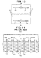
- Heat exchangers having a pair of tanks and a plurality of flat, heat transfer tubes interconnecting the tanks are known. Such heat exchangers may be manufactured by temporarily assembling respective parts and brazing together the assembled parts in a furnace at the same time. In the manufacture of such heat exchangers, for example, as depicted in Fig. 14 , end portions of flat, heat transfer tubes 103 are inserted into respective tube insertion holes 102 formed through a seat plate 101 of a tank 100. Fins 104 are interposed between adjacent heat transfer tubes 103.
- a variety of insertion lengths of respective heat transfer tubes 103 into tank 100 may occur. If the insertion length of heat transfer tube 103 is too long (for example, as in portions P1), flow resistance in tank 100 may increase. On the other hand, if the insertion length of heat transfer tube 103 is too short (for example, as in portions P2), the area for brazing between the outer surface of heat transfer tube 103 and the inner surface of tube insertion hole 102 may decrease, thereby reducing the strength of the bond.
- heat transfer tubes 103 and fins 104 are held by a jig (not shown) from both sides in their stacked direction when the assembled parts are brazed together in a furnace, because of a difference in the coefficient of thermal expansion between the steel jig and the parts of the heat exchanger constructed from an aluminum material or the like, the heat exchanger may be crimped strongly by the jig, and the end portions of heat transfer tubes 103 may be deformed.
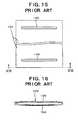
- tube insertion hole 102 of seat plate 101 may be deformed, and the inner surface of the deformed tube insertion hole 102 overlap protruded portion 106. Consequently, the tube insertion length may not be regulated. Further, at that time, if a large force operates from the inner surface side of tube insertion hole 102 against protruded portion 106, tube 105 may be deformed. If the heat transfer tube 105 is deformed, a decrease in brazing strength or an increase in flow resistance, or both, may occur.
- a heat transfer tube of a heat exchanger which may prevent a deformation of a tube end portion, and may prevent an increase in flow resistance and avoid a decrease in brazing strength, thereby providing a heat exchanger capable of higher performance.
- a heat exchanger comprises a pair of tanks and a plurality of flat, heat transfer tubes which place the pair of tanks in communication by inserting each end portion of a heat transfer tube into one of the tanks and extending in parallel to each other.
- the heat exchanger comprises a rib protruding in at least one of an outward and an inward direction (i.e. , away from the interior of the heat exchanger tube or toward the interior of the heat exchanger tube, respectively),from the heat transfer tube and a stopper regulating an insertion length of the heat transfer tube into a tank, which rib and stopper are provided on a surface of an end portion of the heat transfer tube.
- the heat transfer tube comprises a rib protruding in at least one of outer and inner directions of the heat transfer tube and a stopper regulating an insertion length of the heat transfer tube into the tank. Therefore, for example, by means of a rib extending across the width of the heat transfer tube, the strength of the end portion of the heat transfer tube primarily is increased, and a deformation of the heat transfer tube may be reduced or prevented. On the other hand, for example, by engaging a stopper, which protrudes in an outward direction of the heat transfer tube, against an inner surface of a tube insertion hole, the insertion length of the heat transfer tube into a tank may be regulated at a proper length. Therefore, because both a uniform tube insertion length and an increase of the strength of the end portion of the heat transfer tube may be achieved simultaneously and effectively, a higher performance heat exchanger is provided, which avoids an increase of the flow resistance within the tanks and which has superior brazing strength.
- the rib may protrude in either of the outward or inward direction from the heat transfer tube. If the rib protrudes in the inward direction of the heat transfer tube, the rib may regulate a position of an inner fin, which may be disposed within the heat transfer tube, in the axial or longitudinal direction of the heat transfer tube.
- the rib preferably extends across a width or transverse to the axis of the heat transfer tube.
- the strength of the end portion of the heat transfer tube may be increased over a broader area, and a deformation of the tube may be reduced or prevented more properly.
- the extension length of such a rib is not particularly limited, for example, about one-third of the width of the flat, heat transfer tube may be sufficient to achieve the desired rib function.
- the stopper may have, for example, a convex shape and may protrude outwardly from the surface of the end portion of the heat transfer tube.
- stoppers may be disposed at each side of the rib(s) across a width of the heat transfer tube.
- a plurality of ribs may be disposed on the surface of the end portion of the heat transfer tube, and at least one stopper may be disposed between a pair of ribs.
- the stopper With respect to the positional relationship between the rib and the stopper, at least a portion of the stopper extends toward an end of the heat transfer tube beyond the rib(s).
- a portion of the stopper when the end portion of a tube is inserted into a tube insertion hole of a tank, because a portion of the stopper first comes into contact with the inner surface of the tube insertion hole and because an excessive insertion of the tube is regulated, disadvantages, such as a deformation of the tube where an excessive force is received at the inner surface of the tube insertion hole by the rib, may be reduced or avoided.
- a dimension of the stopper in an axial or a longitudinal direction of the heat transfer tube may be greater than a dimension of the rib(s) in the axial or longitudinal direction of the heat transfer tube.
- a diameter of the stopper may be greater than a depth of the rib(s).
- the rib(s) and the stopper(s) may be disposed so as to be connected to each other, e.g. , configured integrally.
- the rib(s) and the stopper(s) may be disposed so as to be independent or separated from each other.
- Such rib(s) and stopper(s), e.g. , configured integrally, may be formed readily by a single process, for example, by pressing.
- a higher performance heat exchanger which prevents an increase of the flow resistance in the tanks and has superior brazing strength, may be achieved.
- Such a higher performance heat exchanger may be applied to a variety of uses for known heat exchanger and, in particular, is suitable as a heat exchanger for use in air conditioning systems for vehicles.
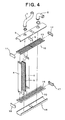
- Figs. 1-8 depict a heat exchanger according to a first embodiment of the present invention.
- heat exchanger 1 comprises a pair of tanks 2 and 3 and a plurality of flat, heat transfer tubes 4 placing tanks 2 and 3 in communication.
- Flat, heat transfer tubes 4 extend in parallel to each other.
- Each end portion of heat transfer tube 4 is inserted into one of tanks 2 and 3 to place tanks 2 and 3 in communication.
- Corrugated fins 5 are interposed between adjacent, heat transfer tubes 4.
- tank 2 is formed from tank member 9, seat plate 10, and caps 11 and 12.
- Barred portion 19 surrounds each tube insertion hole 13.
- the inside of tank 2 is divided into two chambers by a partition 6.
- An inlet pipe 7 is in communication with one chamber, and an outlet pipe 8 is in communication with the other chamber.
- Tank 3 is similar to tank 2, and as depicted in Fig. 4, tank 3 is formed from tank member 14, seat plate 15, and caps 16 and 17.
- Barred portion 19 (depicted in Fig. 5) is formed around each tube insertion hole 18.
- ribs 20 and stoppers 21 are disposed on both surfaces 28 and 29 of each end portion of each flat, heat transfer tube 4.
- Each rib 20 protrudes from the tube surface in an outward direction from heat transfer tube 4.
- Each stopper 21 regulates a tube insertion length of each heat transfer tube 4 into each tube insertion hole 13 or 18.
- rib 20 extends across a width of flat, heat transfer tube 4 ( e.g. , a left/right direction in Fig. 6 ). Rib 20 and each stopper 21 are independent or separated from each other. Although the extension length of rib 20 is not particularly limited, it may be about one third of the width of flat, heat transfer tube 4. Stopper 21 is a convex-shaped protrusion 22 from the tube surface in an outward direction from flat, heat transfer tube 4. In this embodiment, stoppers 21 are disposed on each side of rib 20 in the transverse direction ( i.e. , across the width) of rib 20.
- stopper 21 extends toward an end of flat, heat transfer tube 4 beyond rib 20.
- This structure is achieved by setting a dimension B (a diameter) of stopper 21 greater than a dimension A (a depth) of rib 20 in the longitudinal direction of flat, heat transfer tube 4 (a vertical direction in Fig. 6 ).
- Such ribs 20 and stoppers 21 may be formed readily by a single process, such as by pressing.
- flat, heat transfer tube 4 may be formed by forming ribs 20 and stoppers 21 on four corners of a single plate material 23, and folding the plate material 23 along a folding line C.
- ribs 20 extend across the width of flat, heat transfer tubes 4, the strength of each end portion of tubes 4 may be increased over a broader area, and deformation of tubes 4 may be properly reduced or prevented.
- extension length of ribs 20 is not particularly limited, as long as the length is at least about one-third of the width of flat, heat transfer tube 4, ribs 20 may be sufficient to achieve the desired function.
- stopper(s) 21 extends toward an end of flat, heat transfer tube 4 beyond rib(s) 20, when the end portion of heat transfer tube 4 is inserted into tube insertion hole 13 or 18 of tank 2 or 3, respectively, the outer edge(s) of stopper(s) 21 first comes into contact with the inner surface of tube insertion hole 13 or 18. Therefore, the insertion length of heat transfer tubes 4 is regulated properly, and an excessive insertion may be prevented. Consequently, rib 20 does not receive excessive stress from the inner surface of tube insertion hole 13 or 18, and the end portion of heat transfer tube 4 may not be deformed.
- stoppers 21 may be provided on each side of rib(s) 20 in the transverse direction of rib 20, the orientation of flat, heat transfer tube 4, when the end portion of the tube is inserted into tube insertion hole 13 or 18, may be maintained properly.
- Figs. 9 and 10 depict a flat, heat transfer tube 24 of heat exchanger 1 according to a second embodiment of the present invention.
- ribs 25 and stoppers 26 are disposed on both surfaces 30 and 31 of each end portion of each flat heat transfer tubes 24.
- Each rib 25 protrudes from the tube surface in an outward direction from heat transfer tube 24.
- Each stopper 21 regulates a tube insertion length of heat transfer tube 24 into each tube insertion hole 13 or 18 of tank 2 or 3, respectively.
- each rib 25 extends across a width of flat, heat transfer tube 24 ( e.g. , a left/right direction in Fig. 9 ), and each stopper 26 is a convex-shaped protrusion 27 from the tube surface in the outward direction from flat, heat transfer tube 24. Stoppers 26 may be disposed on each side of each rib 25 in the transverse direction of rib 25, and stoppers 26 and rib 25 are connected continuously to each other.
- stopper 26 extends toward an end of flat heat transfer tube 24 beyond rib 25.
- This structure is achieved by setting a dimension E (a diameter) of stopper 26 greater than a dimension D (a depth) of rib 25 in the axial or longitudinal direction of flat, heat transfer tube 24 ( e.g. , a vertical direction in Fig. 9 ).
- Such ribs 25 and stoppers 26 may be formed readily by a single process, such as by pressing.
- rib 25 extending across the width of flat, heat transfer tube 24 primarily increases the strength of each end portion of tube 24, thereby preventing a deformation thereof
- Stopper 26 primarily regulates the tube insertion length of each end portion of flat, heat transfer tube 24 into tube insertion hole 13 or 18, by engaging holes 13 and 18 at the inner surface of tube insertion hole 13 or 18. Therefore, an increase of the strength of each end portion of flat, heat transfer tube 24 and a uniform tube insertion length of each end portion of flat, heat transfer tube 24 into tank 2 or 3 may be achieved simultaneously and effectively, and a higher performance heat exchanger, which has superior brazing strength and which may prevent an increase of flow resistance within tanks 2 and 3, may be realized.
- stopper 26 extends toward an end of flat, heat transfer tube 24 beyond rib 25, when the end portion of heat transfer tube 24 is inserted into tube insertion hole 13 or 18 of tank 2 or 3, respectively, the outer edge of stopper 26 first comes into contact with the inner surface of tube insertion hole 13 or 18. Therefore, the insertion length of heat transfer tube 24 is regulated properly, and insertion to an excessive length may be prevented. Consequently, rib 25 does not receive an excessive stress from the inner surface of tube insertion hole 13 or 18, and the end portion of heat transfer tube 24 may not be deformed.
- stoppers 26 may be disposed on either side of rib 25 in the transverse direction of rib 25, the orientation of flat, heat transfer tube 24, when the end portion of the tube is inserted into tube insertion hole 13 or 18, may be maintained properly.
- Figs. 11 and 12 depict a flat, heat transfer tube 32 of a heat exchanger 1 according to a third embodiment of the present invention.
- ribs 33 and 34 and stoppers 35 are disposed on either surface 36 and 37 of each end portion of each flat, heat transfer tube 32.
- Ribs 33 and 34 protrude from the tube surface in an outward direction from heat transfer tube 32.
- Each stopper 35 regulates a tube insertion length of each heat transfer tube 32 into tube insertion hole 13 or 18 of tank 2 or 3, respectively.
- two ribs 33 and 34 extending across a width of flat, heat transfer tube 32 ( e.g. , a left/right direction in Fig. 11 ), are disposed in series across the width of flat, heat transfer tube 32.
- Stopper 35 is a convex-shaped protrusion 38 from the tube surface in the outward direction of flat, heat transfer tube 32. Stopper 35 is provided between ribs 33 and 34 across the width of flat, heat transfer tube 32. Ribs 33 and 34 and stopper 35 are independent or separated from each other. Nevertheless, as shown in a modification of the third embodiment depicted in Fig. 13, ribs 33 and 34 and stopper 35 also may be connected to each other.
- stopper 35 extends toward an end of flat, heat transfer tube 32 beyond ribs 33 and 34.
- This structure is achieved by setting a dimension H (a diameter) of stopper 35 greater than dimensions F and G (depths) of ribs 33 and 34 in the axial or longitudinal direction of flat, heat transfer tube 32 ( e.g. , a vertical direction in Fig. 11 ).
- Such ribs 33 and 34 and stoppers 35 may be formed readily by a single process, such as by pressing.
- ribs 33 and 34 extending across the width of flat, heat transfer tube 32 primarily increase the strength of each end portion of tube 32, thereby preventing a deformation thereof.
- Stopper 35 primarily regulates the tube insertion length of each end portion of flat, heat transfer tube 32 into tube insertion hole 13 or 18, by engaging stopper 35 with the inner surface of tube insertion hole 13 or 18. Therefore, an increase of the strength of each end portion of flat, heat transfer tube 32 and a uniform tube insertion length of each end portion of flat, heat transfer tube 32 into tank 2 or 3 may be achieved simultaneously and effectively, and a higher performance heat exchanger, which has superior brazing strength and which may prevent an increase of flow resistance within tanks 2 and 3, may be realized.
- stopper 35 extends toward an end of flat, heat transfer tube 32 beyond ribs 33 and 34, when the end portion of heat transfer tube 32 is inserted into tube insertion hole 13 or 18 of tank 2 or 3, respectively, the outer edge of stopper 35 first comes into contact with the inner surface of tube insertion hole 13 or 18. Therefore, the insertion length of heat transfer tube 32 is regulated properly, and insertion to an excessive length may be prevented. Consequently, ribs 33 and 34 do not receive an excessive stress from the inner surface of tube insertion hole 13 or 18, and the end portion of heat transfer tube 32 may not be deformed.
Landscapes
- Engineering & Computer Science (AREA)
- Physics & Mathematics (AREA)
- Thermal Sciences (AREA)
- Mechanical Engineering (AREA)
- General Engineering & Computer Science (AREA)
- Heat-Exchange Devices With Radiators And Conduit Assemblies (AREA)
- Details Of Heat-Exchange And Heat-Transfer (AREA)
Abstract
Description
Claims (18)
- A heat exchanger comprising a pair of tanks and a plurality of flat, heat transfer tubes placing said pair of tanks in communication by inserting each end portion of a heat transfer tube into one of said tanks and extending in parallel to each other, characterized in that said heat exchanger comprises a rib protruding in at least one of an outward and an inward directions of said heat transfer tube and a stopper regulating an insertion length of said heat transfer tube into a tank, which rib and stopper are disposed on a surface of an end portion of said heat transfer tube.
- The heat exchanger according to claim 1, wherein said rib extends across a width of said heat transfer tube.
- The heat exchanger according to claim 1 or 2, wherein a pair of said stoppers are disposed at each side of said rib in a transverse direction of said heat transfer tube.
- The heat exchanger according to claim 1 or 2, wherein a plurality of ribs are disposed on said surface of said end portion of said heat transfer tube, and said stopper is disposed between ribs.
- The heat exchanger according to any preceding claim, wherein said stopper has a convex shape and protrudes outwardly from said surface of said end portion of said heat transfer tube.
- The heat exchanger according to any preceding claim, wherein at least a portion of said stopper extends toward an end of said heat transfer tube beyond said rib.
- The heat exchanger according to any preceding claim, wherein a diameter of said stopper along said heat transfer tube is greater than a depth of said rib along said heat transfer tube.
- The heat exchanger according to any preceding claim, wherein said rib and said stopper are connected to each other.
- The heat exchanger according to any of claims 1 to 7, wherein said rib and said stopper are separated from each other.
- An air conditioning system comprising said heat exchanger of any preceding claim.
- The air conditioning system according to claim 10, wherein said rib extends across a width of said heat transfer tube.
- The air conditioning system according to claim 10 or 11, wherein a pair of said stoppers are disposed at each side of said rib in a transverse direction of said heat transfer tube.
- The air conditioning system according to claim 10 or 11, wherein a plurality of ribs are disposed on said surface of said end portion of said heat transfer tube, and said stopper is disposed between ribs.
- The air conditioning system according to any of claims 10 to 13, wherein said stopper has a convex shape and protrudes outwardly from said surface of said end portion of said heat transfer tube.
- The air conditioning system according to any of claims 10 to 14, wherein at least a portion of said stopper extends toward an end of said heat transfer tube beyond said rib.
- The air conditioning system according to any of claims 10 to 15, wherein a diameter of said stopper along said heat transfer tube is greater than a depth of said rib along said heat transfer tube.
- The air conditioning system according to any of claims 10 to 16, wherein said rib and said stopper are connected to each other.
- The air conditioning system according to any of claims 10 to 16, wherein said rib and said stopper are separated from each other.
Applications Claiming Priority (2)
| Application Number | Priority Date | Filing Date | Title |
|---|---|---|---|
| JP2004143727 | 2004-05-13 | ||
| JP2004143727A JP2005326066A (en) | 2004-05-13 | 2004-05-13 | Heat exchanger |
Publications (2)
| Publication Number | Publication Date |
|---|---|
| EP1596149A2 true EP1596149A2 (en) | 2005-11-16 |
| EP1596149A3 EP1596149A3 (en) | 2006-10-25 |
Family
ID=34941247
Family Applications (1)
| Application Number | Title | Priority Date | Filing Date |
|---|---|---|---|
| EP05252897A Withdrawn EP1596149A3 (en) | 2004-05-13 | 2005-05-11 | Heat exchangers |
Country Status (3)
| Country | Link |
|---|---|
| US (1) | US7530387B2 (en) |
| EP (1) | EP1596149A3 (en) |
| JP (1) | JP2005326066A (en) |
Families Citing this family (1)
| Publication number | Priority date | Publication date | Assignee | Title |
|---|---|---|---|---|
| CN101688763B (en) * | 2007-04-11 | 2014-08-20 | 贝洱两合公司 | Heat exchanger |
Family Cites Families (13)
| Publication number | Priority date | Publication date | Assignee | Title |
|---|---|---|---|---|
| FR2484071B1 (en) * | 1980-06-05 | 1985-12-13 | Valeo | HOLE PLATE FOR A HEAT EXCHANGER WITH FLUID CIRCULATION TUBES |
| US4458749A (en) * | 1983-04-18 | 1984-07-10 | Ex-Cell-O Corporation | Radiator having reinforced tubes |
| US5458190A (en) * | 1986-07-29 | 1995-10-17 | Showa Aluminum Corporation | Condenser |
| JPH02242095A (en) * | 1989-03-16 | 1990-09-26 | Nippondenso Co Ltd | Heat exchanger |
| FR2715217B1 (en) * | 1994-01-20 | 1996-03-01 | Valeo Thermique Moteur Sa | Heat exchanger tube, in particular for a motor vehicle, process for its conformation and heat exchanger comprising such tubes. |
| DE19651625A1 (en) * | 1996-12-12 | 1998-06-18 | Behr Industrietech Gmbh & Co | Ribbed-tube heat exchange system for charging air cooling |
| JPH10332294A (en) * | 1997-06-03 | 1998-12-15 | Calsonic Corp | Heat exchanger tubes |
| US5941303A (en) * | 1997-11-04 | 1999-08-24 | Thermal Components | Extruded manifold with multiple passages and cross-counterflow heat exchanger incorporating same |
| US6332495B1 (en) * | 1999-06-02 | 2001-12-25 | Long Manufacturing Ltd. | Clip on manifold heat exchanger |
| JP2001041675A (en) * | 1999-07-28 | 2001-02-16 | Mitsubishi Heavy Ind Ltd | Heat exchanger tubes and heat exchangers |
| JP2001248988A (en) * | 2000-03-06 | 2001-09-14 | Mitsubishi Heavy Ind Ltd | Heat exchanger |
| DE60100617T2 (en) * | 2000-10-06 | 2004-06-09 | Visteon Global Technologies, Inc., Dearborn | Manufacture of a tube for a heat exchanger |
| US6830100B2 (en) * | 2001-11-02 | 2004-12-14 | Thermalex, Inc. | Extruded manifold |
-
2004
- 2004-05-13 JP JP2004143727A patent/JP2005326066A/en active Pending
-
2005
- 2005-05-11 EP EP05252897A patent/EP1596149A3/en not_active Withdrawn
- 2005-05-12 US US11/127,199 patent/US7530387B2/en not_active Expired - Fee Related
Also Published As
| Publication number | Publication date |
|---|---|
| US20050252646A1 (en) | 2005-11-17 |
| JP2005326066A (en) | 2005-11-24 |
| EP1596149A3 (en) | 2006-10-25 |
| US7530387B2 (en) | 2009-05-12 |
Similar Documents
| Publication | Publication Date | Title |
|---|---|---|
| EP1231448B1 (en) | Heat exchanger | |
| JP4811258B2 (en) | Heat exchanger | |
| US7201218B2 (en) | Header tank for heat exchanger | |
| US8720535B2 (en) | Heat exchanger, use, and manufacturing process for a heat exchanger | |
| US9644897B2 (en) | Heater core with dual plate pipe connector | |
| JP3760571B2 (en) | Heat exchanger | |
| US20080011456A1 (en) | Heat exchanger having integral elastic regions | |
| US5816320A (en) | Radiator fin construction | |
| US6257325B1 (en) | Heat exchanger | |
| US7174953B2 (en) | Stacking-type, multi-flow, heat exchanger | |
| US5373895A (en) | Heat exchanger | |
| US7530387B2 (en) | Heat exchangers | |
| EP0798530B1 (en) | Heat exchanger | |
| JP3683001B2 (en) | Double stacked heat exchanger | |
| JP3212038B2 (en) | Aluminum heat exchanger | |
| JPH10281693A (en) | Double integrated heat exchanger | |
| JP3797720B2 (en) | Heat exchanger | |
| JP4358961B2 (en) | Evaporator fin | |
| JPH09280774A (en) | Heat exchanger | |
| JPH10141875A5 (en) | ||
| JP4180713B2 (en) | Heat exchanger | |
| JPH10339586A (en) | Heat exchanger | |
| JP4759297B2 (en) | Heat exchanger | |
| JPH11118375A (en) | Heat exchanger tubes | |
| JPH08219680A (en) | Heat-exchanger |
Legal Events
| Date | Code | Title | Description |
|---|---|---|---|
| PUAI | Public reference made under article 153(3) epc to a published international application that has entered the european phase |
Free format text: ORIGINAL CODE: 0009012 |
|
| AK | Designated contracting states |
Kind code of ref document: A2 Designated state(s): AT BE BG CH CY CZ DE DK EE ES FI FR GB GR HU IE IS IT LI LT LU MC NL PL PT RO SE SI SK TR |
|
| AX | Request for extension of the european patent |
Extension state: AL BA HR LV MK YU |
|
| PUAL | Search report despatched |
Free format text: ORIGINAL CODE: 0009013 |
|
| AK | Designated contracting states |
Kind code of ref document: A3 Designated state(s): AT BE BG CH CY CZ DE DK EE ES FI FR GB GR HU IE IS IT LI LT LU MC NL PL PT RO SE SI SK TR |
|
| AX | Request for extension of the european patent |
Extension state: AL BA HR LV MK YU |
|
| 17P | Request for examination filed |
Effective date: 20070417 |
|
| AKX | Designation fees paid |
Designated state(s): AT BE BG CH CY CZ DE DK EE ES FI FR GB GR HU IE IS IT LI LT LU MC NL PL PT RO SE SI SK TR |
|
| 17Q | First examination report despatched |
Effective date: 20071008 |
|
| STAA | Information on the status of an ep patent application or granted ep patent |
Free format text: STATUS: THE APPLICATION IS DEEMED TO BE WITHDRAWN |
|
| 18D | Application deemed to be withdrawn |
Effective date: 20080219 |