EP1596146A2 - Heat exchangers and air conditioning systems including such heat exchangers - Google Patents
Heat exchangers and air conditioning systems including such heat exchangers Download PDFInfo
- Publication number
- EP1596146A2 EP1596146A2 EP05252699A EP05252699A EP1596146A2 EP 1596146 A2 EP1596146 A2 EP 1596146A2 EP 05252699 A EP05252699 A EP 05252699A EP 05252699 A EP05252699 A EP 05252699A EP 1596146 A2 EP1596146 A2 EP 1596146A2
- Authority
- EP
- European Patent Office
- Prior art keywords
- heat exchanger
- header pipe
- core
- header
- pair
- Prior art date
- Legal status (The legal status is an assumption and is not a legal conclusion. Google has not performed a legal analysis and makes no representation as to the accuracy of the status listed.)
- Withdrawn
Links
- 238000004378 air conditioning Methods 0.000 title claims description 9
- 238000004891 communication Methods 0.000 claims abstract description 6
- 239000003507 refrigerant Substances 0.000 claims description 33
- 238000009833 condensation Methods 0.000 claims description 11
- 230000005494 condensation Effects 0.000 claims description 11
- 239000002274 desiccant Substances 0.000 claims description 7
- 238000011144 upstream manufacturing Methods 0.000 claims description 7
- 238000004781 supercooling Methods 0.000 claims description 4
- 239000007788 liquid Substances 0.000 abstract description 7
- 238000003780 insertion Methods 0.000 abstract description 6
- 230000037431 insertion Effects 0.000 abstract description 6
- 230000008030 elimination Effects 0.000 abstract 1
- 238000003379 elimination reaction Methods 0.000 abstract 1
- 238000005192 partition Methods 0.000 description 8
- 238000009434 installation Methods 0.000 description 6
- 230000003247 decreasing effect Effects 0.000 description 4
- 239000000463 material Substances 0.000 description 4
- 238000004519 manufacturing process Methods 0.000 description 3
- 238000001125 extrusion Methods 0.000 description 2
- 238000000465 moulding Methods 0.000 description 2
- 230000005855 radiation Effects 0.000 description 2
- 238000005452 bending Methods 0.000 description 1
- 238000000034 method Methods 0.000 description 1
- 238000005057 refrigeration Methods 0.000 description 1
- 230000000717 retained effect Effects 0.000 description 1
Images



Classifications
-
- F—MECHANICAL ENGINEERING; LIGHTING; HEATING; WEAPONS; BLASTING
- F28—HEAT EXCHANGE IN GENERAL
- F28D—HEAT-EXCHANGE APPARATUS, NOT PROVIDED FOR IN ANOTHER SUBCLASS, IN WHICH THE HEAT-EXCHANGE MEDIA DO NOT COME INTO DIRECT CONTACT
- F28D1/00—Heat-exchange apparatus having stationary conduit assemblies for one heat-exchange medium only, the media being in contact with different sides of the conduit wall, in which the other heat-exchange medium is a large body of fluid, e.g. domestic or motor car radiators
- F28D1/02—Heat-exchange apparatus having stationary conduit assemblies for one heat-exchange medium only, the media being in contact with different sides of the conduit wall, in which the other heat-exchange medium is a large body of fluid, e.g. domestic or motor car radiators with heat-exchange conduits immersed in the body of fluid
- F28D1/04—Heat-exchange apparatus having stationary conduit assemblies for one heat-exchange medium only, the media being in contact with different sides of the conduit wall, in which the other heat-exchange medium is a large body of fluid, e.g. domestic or motor car radiators with heat-exchange conduits immersed in the body of fluid with tubular conduits
- F28D1/053—Heat-exchange apparatus having stationary conduit assemblies for one heat-exchange medium only, the media being in contact with different sides of the conduit wall, in which the other heat-exchange medium is a large body of fluid, e.g. domestic or motor car radiators with heat-exchange conduits immersed in the body of fluid with tubular conduits the conduits being straight
- F28D1/0535—Heat-exchange apparatus having stationary conduit assemblies for one heat-exchange medium only, the media being in contact with different sides of the conduit wall, in which the other heat-exchange medium is a large body of fluid, e.g. domestic or motor car radiators with heat-exchange conduits immersed in the body of fluid with tubular conduits the conduits being straight the conduits having a non-circular cross-section
-
- F—MECHANICAL ENGINEERING; LIGHTING; HEATING; WEAPONS; BLASTING
- F25—REFRIGERATION OR COOLING; COMBINED HEATING AND REFRIGERATION SYSTEMS; HEAT PUMP SYSTEMS; MANUFACTURE OR STORAGE OF ICE; LIQUEFACTION SOLIDIFICATION OF GASES
- F25B—REFRIGERATION MACHINES, PLANTS OR SYSTEMS; COMBINED HEATING AND REFRIGERATION SYSTEMS; HEAT PUMP SYSTEMS
- F25B39/00—Evaporators; Condensers
- F25B39/04—Condensers
-
- F—MECHANICAL ENGINEERING; LIGHTING; HEATING; WEAPONS; BLASTING
- F28—HEAT EXCHANGE IN GENERAL
- F28D—HEAT-EXCHANGE APPARATUS, NOT PROVIDED FOR IN ANOTHER SUBCLASS, IN WHICH THE HEAT-EXCHANGE MEDIA DO NOT COME INTO DIRECT CONTACT
- F28D1/00—Heat-exchange apparatus having stationary conduit assemblies for one heat-exchange medium only, the media being in contact with different sides of the conduit wall, in which the other heat-exchange medium is a large body of fluid, e.g. domestic or motor car radiators
- F28D1/02—Heat-exchange apparatus having stationary conduit assemblies for one heat-exchange medium only, the media being in contact with different sides of the conduit wall, in which the other heat-exchange medium is a large body of fluid, e.g. domestic or motor car radiators with heat-exchange conduits immersed in the body of fluid
- F28D1/04—Heat-exchange apparatus having stationary conduit assemblies for one heat-exchange medium only, the media being in contact with different sides of the conduit wall, in which the other heat-exchange medium is a large body of fluid, e.g. domestic or motor car radiators with heat-exchange conduits immersed in the body of fluid with tubular conduits
- F28D1/0408—Multi-circuit heat exchangers, e.g. integrating different heat exchange sections in the same unit or heat exchangers for more than two fluids
- F28D1/0426—Multi-circuit heat exchangers, e.g. integrating different heat exchange sections in the same unit or heat exchangers for more than two fluids with units having particular arrangement relative to the large body of fluid, e.g. with interleaved units or with adjacent heat exchange units in common air flow or with units extending at an angle to each other or with units arranged around a central element
- F28D1/0435—Combination of units extending one behind the other
-
- F—MECHANICAL ENGINEERING; LIGHTING; HEATING; WEAPONS; BLASTING
- F28—HEAT EXCHANGE IN GENERAL
- F28D—HEAT-EXCHANGE APPARATUS, NOT PROVIDED FOR IN ANOTHER SUBCLASS, IN WHICH THE HEAT-EXCHANGE MEDIA DO NOT COME INTO DIRECT CONTACT
- F28D1/00—Heat-exchange apparatus having stationary conduit assemblies for one heat-exchange medium only, the media being in contact with different sides of the conduit wall, in which the other heat-exchange medium is a large body of fluid, e.g. domestic or motor car radiators
- F28D1/02—Heat-exchange apparatus having stationary conduit assemblies for one heat-exchange medium only, the media being in contact with different sides of the conduit wall, in which the other heat-exchange medium is a large body of fluid, e.g. domestic or motor car radiators with heat-exchange conduits immersed in the body of fluid
- F28D1/04—Heat-exchange apparatus having stationary conduit assemblies for one heat-exchange medium only, the media being in contact with different sides of the conduit wall, in which the other heat-exchange medium is a large body of fluid, e.g. domestic or motor car radiators with heat-exchange conduits immersed in the body of fluid with tubular conduits
- F28D1/047—Heat-exchange apparatus having stationary conduit assemblies for one heat-exchange medium only, the media being in contact with different sides of the conduit wall, in which the other heat-exchange medium is a large body of fluid, e.g. domestic or motor car radiators with heat-exchange conduits immersed in the body of fluid with tubular conduits the conduits being bent, e.g. in a serpentine or zig-zag
- F28D1/0471—Heat-exchange apparatus having stationary conduit assemblies for one heat-exchange medium only, the media being in contact with different sides of the conduit wall, in which the other heat-exchange medium is a large body of fluid, e.g. domestic or motor car radiators with heat-exchange conduits immersed in the body of fluid with tubular conduits the conduits being bent, e.g. in a serpentine or zig-zag the conduits having a non-circular cross-section
-
- F—MECHANICAL ENGINEERING; LIGHTING; HEATING; WEAPONS; BLASTING
- F28—HEAT EXCHANGE IN GENERAL
- F28F—DETAILS OF HEAT-EXCHANGE AND HEAT-TRANSFER APPARATUS, OF GENERAL APPLICATION
- F28F9/00—Casings; Header boxes; Auxiliary supports for elements; Auxiliary members within casings
- F28F9/02—Header boxes; End plates
- F28F9/0243—Header boxes having a circular cross-section
-
- F—MECHANICAL ENGINEERING; LIGHTING; HEATING; WEAPONS; BLASTING
- F25—REFRIGERATION OR COOLING; COMBINED HEATING AND REFRIGERATION SYSTEMS; HEAT PUMP SYSTEMS; MANUFACTURE OR STORAGE OF ICE; LIQUEFACTION SOLIDIFICATION OF GASES
- F25B—REFRIGERATION MACHINES, PLANTS OR SYSTEMS; COMBINED HEATING AND REFRIGERATION SYSTEMS; HEAT PUMP SYSTEMS
- F25B2500/00—Problems to be solved
- F25B2500/01—Geometry problems, e.g. for reducing size
-
- F—MECHANICAL ENGINEERING; LIGHTING; HEATING; WEAPONS; BLASTING
- F25—REFRIGERATION OR COOLING; COMBINED HEATING AND REFRIGERATION SYSTEMS; HEAT PUMP SYSTEMS; MANUFACTURE OR STORAGE OF ICE; LIQUEFACTION SOLIDIFICATION OF GASES
- F25B—REFRIGERATION MACHINES, PLANTS OR SYSTEMS; COMBINED HEATING AND REFRIGERATION SYSTEMS; HEAT PUMP SYSTEMS
- F25B40/00—Subcoolers, desuperheaters or superheaters
- F25B40/02—Subcoolers
Definitions
- the present invention relates to heat exchangers, in particular, parallel-flow type heat exchangers, in which heat transfer tubes are disposed between a pair of header pipes in parallel to each other. More specifically, the invention relates to heat exchangers which are suitable for use as condensers of an air conditioning systems for vehicles, particularly, as a subcooling-type condensers.
- Parallel-flow type heat exchangers in which heat transfer tubes are disposed between a pair of header pipes in parallel to each other, are known.
- at least one header pipe requires a relatively large capacity, and a cross-sectional area of the header pipes is required to be greater than a width of each of heat transfer tube extending in parallel, i.e. , a width of a heat transfer tube in a direction of air flow across a heat exchanger.
- a condenser of an air conditioning system for vehicles in particular, in a subcooling-type condenser, one header pipe has a cross-sectional area greater than that of the other header pipe and requires a liquid storing function.
- a heat exchanger 1 includes a pair of header pipes 2 and 3, a plurality of flat-type heat transfer tubes 4 extending between and placing the pair of header pipes 2 and 3 in communication and extending in parallel to each other, and a plurality of corrugated fins 5 provided between adjacent heat transfer tubes 4 and on outermost portions of the outermost tubes 4.
- An inlet 6 and an outlet 7 for refrigerant are provided on header pipe 2, and a partition 8 is provided in header pipe 2.
- Header pipe 3 performs a liquid storing function and a moisture removing function.
- Header pipe 3 for example, includes a unit 11, which has a desiccant unit 9 at its upper portion holding a bag containing desiccant for removing moisture from the refrigerant and has a strainer 10 at its lower portion for removing foreign materials from the refrigerant, and unit 11 is detachably retained in header pipe 3 by a holding plate 12 having a communication portion at its central position.
- a core portion 13 of heat exchanger 1 is divided into a first portion located above the position of partition 8, which is formed as a refrigerant condensation core portion 14 for condensing refrigerant, and a second portion located below the position of partition 8, which is formed as a subcooling core portion 15 for supercooling refrigerant condensed by refrigerant condensation core portion 14.
- refrigerant flows through inlet 6 into the upper portion of header pipe 2 above partition 8 flows through and is condensed in first or refrigerant condensation core portion 14.
- a receiver drier may be formed integrally with a condenser without providing other components, and a compact and efficient structure of a drier, e.g. , unit 11 including desiccant unit 9, interchangeably positioned in header pipe 3 may be achieved.
- Such heat exchangers 1 because of their compact structure, are suitable as condensers of an air conditioning system for vehicles, for which an installation space is limited.
- header pipe 3 including unit 11 with the above-described structure must be enlarged, the following problems may occur.
- header pipe 21 having a circular cross-section as depicted in Fig. 2 , is employed as the above-described header pipe 3
- header pipe 21, which becomes an exit portion of refrigerant condensation core portion 14 and an entrance portion of subcooling core portion 15 projects significantly forward and backward relative to the width of heat transfer tube 4 in the direction of air flow across heat exchanger 1.
- a mounting layout of a vehicle so that the condenser, e.g. , heat exchanger 1, and a radiator 30 are disposed on a front-to-rear axis, the heat radiation portions of heat transfer tubes 4 and radiator 30 are separated significantly from each other.
- the thickness of the condenser plus that of radiator 30 in this disposition becomes significant, and, therefore, it is a disadvantageous mounting layout for a vehicle. Because an amount of air passing through the condenser may decrease due to air leakage between the condenser and radiator 30, the performance of the condenser may decrease.
- a structure of a condenser may be employed wherein a center position of a header pipe having a larger cross-section is disposed to be offset to one side in the direction of air flow across the heat exchanger, relative to the position of the center of the heat exchanger in the direction of air flow, namely, relative to the position of the center of heat transfer tube 4 in the direction of air flow (Arrow A) across the heat exchanger or, as depicted in Fig. 3, in a direction away from radiator 30.
- a length 42 of tube 4 to which tube 4 is inserted into a header pipe 41 increases significantly, and a diameter of a contained unit 43 must be decreased in order to avoid the interference between the end of the tube 4 and contained unit 43.
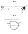
- a header pipe 51 may be formed with a cross-section having a partially flat surface 55 as depicted in Fig. 5.
- insertion holes for heat transfer tubes 4 are formed through the portion of a flat surface 55 of header pipe 51, and the position of the center of the cross-section of header pipe 51 is offset to one side in the direction of air flow (Arrow A) across the heat exchanger.
- Arrow A direction of air flow
- header pipe 51 because the cross-sectional shape of the interior of header pipe 51 is not circular, when the inner header pressure increases, deformation occurs, particularly in the portion forming the above-described flat surface 55 and a portion forming an adjacent flat surface. Thus, the pressure resistance of header pipe 51 may decrease.
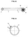
- a structure of a condenser may be employed wherein the outer surface of a portion of header pipe 52, which is adapted to receive the heat transfer tubes, is formed as a flat surface 56, and the cross-sectional shape of the interior of header pipe 52 is circular.
- Such a structure is described in Japanese Patent Application Publication No. JP-A-2005-83719.
- the size of a thickened portion 53 increases, the weight and the cost of header pipe 52 may increase.
- header pipe 52 usually is formed by extrusion, because of the presence of thickened portion 53, a more strict dimensional accuracy is required at the time of molding as compared with tubes having a circular cross-section. Consequently, productivity may decrease.
- a parallel-flow type heat exchanger in which a cross-sectional area of at least one header pipe is increased, which may employ an offset disposition of the header pipe in a direction of air flow across the heat exchanger without increasing the tube insertion length into the header pipe or a reduction of a diameter of a unit to be contained in the header pipe, or both. It is an advantage of such heat exchangers that a decrease of a pressure resistance of the header pipe may be reduced or eliminated. Further, a lighter weight and lower cost heat exchanger may be achieved while increasing the productivity heat exchanger manufacturing methods.
- a heat exchanger comprises a pair of header pipes, and a plurality of heat transfer tubes extending between and placing the pair of header pipes in communication and extending in parallel to each other to form a parallel-flow type heat exchanger core.
- the heat exchanger core is bent, e.g. , formed in segments and the segments are set at an angle with respect to each other, so that relative to a center portion of the core, at least one of the pair of header pipes is offset in a direction of air flow across the heat exchanger.
- the heat exchanger core e.g. , the heat exchanger core through all heat transfer tubes
- the heat exchanger core is bent, so that relative to the center portion of the heat exchanger core, at least one of the pair of header pipes is offset in the direction of air flow across the heat exchanger.
- the heat exchanger core may be bent toward an upstream side in the air flow direction, i.e. , away from the adjacent component.
- an adjacent component e.g.
- the heat exchanger core may be bent toward a downstream side in the air flow direction, i.e. , towards the adjacent component. Therefore, in a parallel-flow type heat exchanger for which it is desirable to increase a cross-sectional area of at least one header pipe, a gap between an adjacent component, e.g. , a radiator, and the heat transfer tubes of the heat exchanger core may be reduced. Namely, an offset disposition of the header pipe in the direction of air flow across the heat exchanger may be achieved, without increasing the length of tube insertion into the header pipe and without decreasing the diameter of a unit, e.g. , a unit comprising a desiccant, contained in the header pipe.
- a unit e.g. , a unit comprising a desiccant
- the above-described at least one header pipe may be formed from a pipe having a circular cross-section.
- the header pipes' inner cross-sectional shape may be circular. Therefore, an internal pressure is received uniformly by an inner surface of the header pipe, and even if a large internal pressure is applied, deformation of the header pipe may be reduced or eliminated, and a reduction of the pressure resistance of the header pipe may be reduced or eliminated.
- a thickened portion of the head pipe is not necessary, the productivity of methods for manufacturing such heat exchangers may be increased, and a lighter weight and lower cost heat exchanger may be achieved than known heat exchangers.
- Such heat exchangers according to the present invention are suitable as subcooling-type heat exchangers. Namely, they are suitable as subcooling-type heat exchangers whose heat exchanger cores comprise a refrigerant condensation core portion for condensing refrigerant and a subcooling core portion for supercooling refrigerant condensed by the refrigerant condensation core portion.
- heat exchangers according to the present invention are suitable, particularly as a condenser, for use in an air conditioning systems for vehicles, for which there is limited installation space.
- a structure may be employed, in which the header pipe is offset to one side of the direction of air flow across the heat exchanger without decreasing the pressure resistance of the header pipe and without increasing the insertion length of heat transfer tubes or decreasing the diameter of a unit contained in the header pipe, or both.
- Such heat exchangers have an outer shape permitting an efficient layout while achieving a desirable performance. Therefore, even if components, such as a radiator, are disposed adjacent to the heat exchanger, as described above, the heat radiation portions of the radiator and the heat transfer tubes need not be greatly separated from each other.
- the thickness of the heat exchanger, e.g. , the condenser, and another component, e.g. , the radiator need not increase; and an amount of air passing through the heat exchanger and another adjacent component need not decrease due to air leakage between the heat exchanger and the other component.
- a heat exchanger according to an embodiment of the present invention is depicted.
- Heat exchangers according to the present invention are suitable for use as condensers in air conditioning systems for vehicles, in particular, as subcooling-type condensers.
- a known subcooling-type condenser is depicted in Fig. 1.
- a heat exchanger such as subcooling-type condenser 1
- Inlet 6 and outlet 7 for refrigerant are provided on header pipe 2, and partition 8 is provided in the header pipe 2.
- Header pipe 3 is formed as a header pipe having a larger diameter and having an larger interior capacity.
- unit 11 includes desiccant unit 9 at its upper portion holding a bag of desiccant for removing moisture and has strainer 10 at its lower portion for removing foreign materials. Further, unit 11 is held detachably in header pipe 3 by holding plate 12 having a communication opening at its central position.
- a portion of core 13 located above partition 8 is formed as a first or refrigerant condensation core portion 14 for condensing refrigerant, and a portion of core 13 located below partition 8 is formed as subcooling core portion 15 for supercooling refrigerant condensed by refrigerant condensation core portion 14.
- Refrigerant having passed through refrigerant condensation core portion 14 and having been condensed therein flows into header pipe 3.
- Moisture and foreign materials are removed from the refrigerant flowing into header pipe 3
- liquefied refrigerant is stored temporarily in the lower portion of header pipe 3, particularly, in lower portion 3a in header pipe 3, and therefrom the refrigerant flows into subcooling core portion 15 and is supercooled therein. Consequently, a structure for subcooling-type condenser 1 is achieved, wherein a drier of a refrigeration or air conditioning system is formed integrally within a condenser, without providing other components.
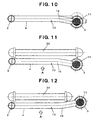
- heat exchanger core 13 is bent, as depicted in Fig. 10 , so that relative to the center portion of the core, at least one header pipe 3 is offset in the direction of air flow across heat exchanger 1.
- a radiator 30 is disposed on a downstream side of the air flow as an adjacent component.
- header pipe 3 and radiator 30 may be prevented, the gap between header pipe 3 and radiator 30 may be reduced, and the amount of air which does not pass through condenser 1 due to air leakage between condenser 1 and radiator 30 may be reduced or eliminated. Namely, without increasing of the tube insertion length into header pipe 3 or reducing the diameter of unit 11 contained in header pipe 3, or both, the offset disposition of header pipe 3 in the direction of air flow across condenser 1 may be achieved.
- header pipe 3 may be made from a pipe having a circular cross-section
- shape of the interior cross-section also may be circular. Therefore, an internal pressure is applied uniformly to the inner surface of header pipe 3, and even if a significant internal pressure is applied thereto, deformation of header pipe 3 may be reduced or eliminated, and a reduction in the pressure resistance of header pipe 3 may be reduced or eliminated.
- a thickened portion is no longer necessary, the productivity of molding such components by extrusion may be increased, and lighter weight and lower cost heat exchangers may be achieved.
- Fig. 12 depicts a subcooling-type condenser according to another embodiment of the present invention.
- heat exchanger core 13 as a whole, is bent in an upstream direction of the air flow, opposite to that depicted in Fig. 11 , if contact between header pipe 3 with an adjacent component disposed on an upstream side of the air flow is to be avoided, rather than with radiator 30; exchanger core 13, as a whole, may be bent, as depicted in Fig. 12 , in a downstream direction of the air flow, i.e. , toward the side of radiator 30.
- interference between header pipe 3 and the adjacent component disposed on the upstream side of the air flow may be prevented, and an enhanced performance and a lighter weight condenser may be obtained by manufacturing methods achieving increased productivity and at a lower cost.
- Structure according to the present invention may be applied to any parallel-flow type heat exchanger requiring a diameter of at least one header pipe to be larger than the other header pipe.
- a condenser of an air conditioning system for vehicles, and in particular, a subcooling-type condenser may be manufactured to include this structure.
Landscapes
- Engineering & Computer Science (AREA)
- Physics & Mathematics (AREA)
- Thermal Sciences (AREA)
- Mechanical Engineering (AREA)
- General Engineering & Computer Science (AREA)
- Heat-Exchange Devices With Radiators And Conduit Assemblies (AREA)
- Air-Conditioning For Vehicles (AREA)
Abstract
Description
Claims (7)
- A heat exchanger comprising a pair of header pipes and a plurality of heat transfer tubes extending between and placing said pair of header pipes in communication and extending in parallel to each other to form a parallel-flow type heat exchanger core wherein said heat exchanger core bent, so that relative to a center portion of said core, at least one of said pair of header pipes is offset in a direction of air flow across said heat exchanger.
- The heat exchanger according to claim 1, wherein said heat exchanger core is bent toward an upstream side of said air flow direction.
- The heat exchanger according to claim 1, wherein said heat exchanger core is bent toward a downstream side of said air flow direction.
- The heat exchanger according to any of claims 1 to 3, wherein a unit comprising a desiccant is contained in said at least one of said pair of header pipes.
- The heat exchanger according to any of claims 1 to 4, wherein cross-sectional areas of interiors of each of said pair of header pipes are not equal, and at least one of said pair of header pipe has a larger cross-sectional area.
- The heat exchanger according to any of claims 1 to 5, wherein said heat exchanger is a subcooling-type heat exchanger, and said heat exchanger core comprises a refrigerant condensation core portion for condensing refrigerant and a subcooling core portion for supercooling refrigerant condensed by said refrigerant condensation core portion.
- An air conditioning system for vehicles comprising said heat exchanger of any of claims 1 to 6.
Applications Claiming Priority (2)
| Application Number | Priority Date | Filing Date | Title |
|---|---|---|---|
| JP2004139608 | 2004-05-10 | ||
| JP2004139608A JP2005321151A (en) | 2004-05-10 | 2004-05-10 | Heat exchanger |
Publications (2)
| Publication Number | Publication Date |
|---|---|
| EP1596146A2 true EP1596146A2 (en) | 2005-11-16 |
| EP1596146A3 EP1596146A3 (en) | 2006-11-02 |
Family
ID=34941116
Family Applications (1)
| Application Number | Title | Priority Date | Filing Date |
|---|---|---|---|
| EP05252699A Withdrawn EP1596146A3 (en) | 2004-05-10 | 2005-04-29 | Heat exchangers and air conditioning systems including such heat exchangers |
Country Status (3)
| Country | Link |
|---|---|
| US (1) | US20050247439A1 (en) |
| EP (1) | EP1596146A3 (en) |
| JP (1) | JP2005321151A (en) |
Cited By (1)
| Publication number | Priority date | Publication date | Assignee | Title |
|---|---|---|---|---|
| WO2006087100A1 (en) * | 2005-02-17 | 2006-08-24 | Behr Gmbh & Co. Kg | Heat exchanger in particular for a heat exchanger unit and heat exchanger unit |
Families Citing this family (8)
| Publication number | Priority date | Publication date | Assignee | Title |
|---|---|---|---|---|
| JP5732258B2 (en) | 2010-02-16 | 2015-06-10 | 株式会社ケーヒン・サーマル・テクノロジー | Capacitor |
| JP2011185562A (en) * | 2010-03-10 | 2011-09-22 | Showa Denko Kk | Condenser |
| JP2012093091A (en) * | 2012-02-17 | 2012-05-17 | Mitsubishi Electric Corp | Heat exchanger and refrigeration air conditioning device |
| CN103968610B (en) * | 2013-02-05 | 2016-07-06 | 珠海格力电器股份有限公司 | Air conditioner and micro-channel heat exchanger thereof |
| WO2015025365A1 (en) | 2013-08-20 | 2015-02-26 | 三菱電機株式会社 | Heat exchanger, air conditioner, and refrigeration cycle device |
| JP6222042B2 (en) * | 2014-05-23 | 2017-11-01 | 株式会社デンソー | Laminate heat exchanger |
| JP7227457B2 (en) * | 2018-11-07 | 2023-02-22 | ダイキン工業株式会社 | heat exchangers and air conditioners |
| CN113748302B (en) * | 2020-03-03 | 2023-08-25 | 电装空调机器有限公司 | Liquid receiver integrated condenser |
Family Cites Families (19)
| Publication number | Priority date | Publication date | Assignee | Title |
|---|---|---|---|---|
| US2105267A (en) * | 1935-03-13 | 1938-01-11 | Robertson John Hogg | Charge cooler |
| US2331634A (en) * | 1941-12-20 | 1943-10-12 | Young Radiator Co | Convector heater |
| US3598179A (en) * | 1968-09-10 | 1971-08-10 | Louis F Giauque | Heat exchanger |
| US3722583A (en) * | 1971-02-22 | 1973-03-27 | Arrow Pneumatics Inc | Refrigerated air dryer |
| GB1346042A (en) * | 1972-08-22 | 1974-02-06 | United Stirling Ab & Co | Hot gas enginge heater heads |
| JPS63154981U (en) * | 1987-03-30 | 1988-10-12 | ||
| JP2997818B2 (en) * | 1990-09-07 | 2000-01-11 | 昭和アルミニウム株式会社 | Bent heat exchanger |
| JP3305460B2 (en) * | 1993-11-24 | 2002-07-22 | 昭和電工株式会社 | Heat exchanger |
| IL109269A (en) * | 1994-04-10 | 1996-10-31 | Magen Plastic | Heat exchanger |
| JP3644077B2 (en) * | 1995-07-18 | 2005-04-27 | 株式会社デンソー | Refrigeration cycle |
| JPH11148796A (en) * | 1997-11-14 | 1999-06-02 | Toyo Radiator Co Ltd | Composite heat exchanger and method of manufacturing the same |
| DE19830757A1 (en) * | 1998-07-09 | 2000-01-13 | Behr Gmbh & Co | Air conditioning system especially for a motor vehicle |
| JP2001041617A (en) * | 1999-07-23 | 2001-02-16 | Calsonic Kansei Corp | Condenser |
| US6260379B1 (en) * | 1999-12-01 | 2001-07-17 | Visteon Global Technologies, Inc. | Condenser with integral receiver dryer |
| WO2003040640A1 (en) * | 2001-11-08 | 2003-05-15 | Zexel Valeo Climate Control Corporation | Heat exchanger and tube for heat exchanger |
| JP2003185296A (en) * | 2001-12-14 | 2003-07-03 | Sanden Corp | Heat exchanger |
| DE10223712C1 (en) * | 2002-05-28 | 2003-10-30 | Thermo King Deutschland Gmbh | Climate-control device for automobile with modular heat exchanger in heat exchanger fluid circuit adaptable for different automobile types |
| US6880620B2 (en) * | 2002-06-25 | 2005-04-19 | Delphi Technologies, Inc. | Heating, ventilating, and air conditioning module having an improved heater core configuration |
| US7503382B2 (en) * | 2002-09-10 | 2009-03-17 | Gac Corporation | Heat exchanger |
-
2004
- 2004-05-10 JP JP2004139608A patent/JP2005321151A/en active Pending
-
2005
- 2005-04-29 EP EP05252699A patent/EP1596146A3/en not_active Withdrawn
- 2005-05-05 US US11/122,000 patent/US20050247439A1/en not_active Abandoned
Cited By (1)
| Publication number | Priority date | Publication date | Assignee | Title |
|---|---|---|---|---|
| WO2006087100A1 (en) * | 2005-02-17 | 2006-08-24 | Behr Gmbh & Co. Kg | Heat exchanger in particular for a heat exchanger unit and heat exchanger unit |
Also Published As
| Publication number | Publication date |
|---|---|
| EP1596146A3 (en) | 2006-11-02 |
| US20050247439A1 (en) | 2005-11-10 |
| JP2005321151A (en) | 2005-11-17 |
Similar Documents
| Publication | Publication Date | Title |
|---|---|---|
| US6470703B2 (en) | Subcooling-type condenser | |
| US20070289723A1 (en) | Internal heat exchanger with calibrated coil-shaped fin tube | |
| US6260379B1 (en) | Condenser with integral receiver dryer | |
| US5450896A (en) | Two-piece header | |
| US20110073277A1 (en) | Adapter for heat exchanger | |
| EP2097707B1 (en) | Heat exchanger design for improved performance and manufacturability | |
| US6341647B1 (en) | Separator-integrated condenser for vehicle air conditioner | |
| US5765633A (en) | Condenser for a refrigerating circuit | |
| EP1104877B1 (en) | Condenser with integral receiver dryer | |
| US7174953B2 (en) | Stacking-type, multi-flow, heat exchanger | |
| KR100268098B1 (en) | heat transmitter | |
| US20050247439A1 (en) | Heat exchangers and air conditioning systems including such heat exchangers | |
| EP1426714A1 (en) | Refrigerating system and condenser for decompression tube system | |
| JP4207333B2 (en) | Condenser with integrated receiver | |
| JP2011185562A (en) | Condenser | |
| US20070056718A1 (en) | Heat exchanger and duplex type heat exchanger | |
| EP1319908B1 (en) | Heat exchanger | |
| CN100408944C (en) | a heat exchanger | |
| US20060266502A1 (en) | Multi-flow condenser for air conditioning systems | |
| EP3263375B1 (en) | Vehicle air-conditioning apparatus | |
| US5368097A (en) | Heat exchanger | |
| JP5034401B2 (en) | Integrated heat exchanger | |
| US6684662B2 (en) | Refrigeration system, and condenser for use in decompressing-tube system | |
| JP3920099B2 (en) | Heat exchanger | |
| US6971251B2 (en) | Integrated condenser/receiver |
Legal Events
| Date | Code | Title | Description |
|---|---|---|---|
| PUAI | Public reference made under article 153(3) epc to a published international application that has entered the european phase |
Free format text: ORIGINAL CODE: 0009012 |
|
| AK | Designated contracting states |
Kind code of ref document: A2 Designated state(s): AT BE BG CH CY CZ DE DK EE ES FI FR GB GR HU IE IS IT LI LT LU MC NL PL PT RO SE SI SK TR |
|
| AX | Request for extension of the european patent |
Extension state: AL BA HR LV MK YU |
|
| PUAL | Search report despatched |
Free format text: ORIGINAL CODE: 0009013 |
|
| AK | Designated contracting states |
Kind code of ref document: A3 Designated state(s): AT BE BG CH CY CZ DE DK EE ES FI FR GB GR HU IE IS IT LI LT LU MC NL PL PT RO SE SI SK TR |
|
| AX | Request for extension of the european patent |
Extension state: AL BA HR LV MK YU |
|
| RIC1 | Information provided on ipc code assigned before grant |
Ipc: F28D 1/047 20060101ALI20060927BHEP Ipc: F25B 39/04 20060101ALI20060927BHEP Ipc: F28D 1/04 20060101ALI20060927BHEP Ipc: F28D 1/053 20060101AFI20050818BHEP |
|
| AKX | Designation fees paid | ||
| REG | Reference to a national code |
Ref country code: DE Ref legal event code: 8566 |
|
| STAA | Information on the status of an ep patent application or granted ep patent |
Free format text: STATUS: THE APPLICATION IS DEEMED TO BE WITHDRAWN |
|
| 18D | Application deemed to be withdrawn |
Effective date: 20070503 |