EP1596132A1 - Nozzle - Google Patents
Nozzle Download PDFInfo
- Publication number
- EP1596132A1 EP1596132A1 EP05252832A EP05252832A EP1596132A1 EP 1596132 A1 EP1596132 A1 EP 1596132A1 EP 05252832 A EP05252832 A EP 05252832A EP 05252832 A EP05252832 A EP 05252832A EP 1596132 A1 EP1596132 A1 EP 1596132A1
- Authority
- EP
- European Patent Office
- Prior art keywords
- arrays
- fuel
- vanes
- air
- passageways
- Prior art date
- Legal status (The legal status is an assumption and is not a legal conclusion. Google has not performed a legal analysis and makes no representation as to the accuracy of the status listed.)
- Granted
Links
- 239000000446 fuel Substances 0.000 claims abstract description 55
- 238000003491 array Methods 0.000 claims abstract description 26
- 239000000203 mixture Substances 0.000 claims abstract description 9
- 238000007599 discharging Methods 0.000 claims abstract description 6
- 238000002485 combustion reaction Methods 0.000 claims description 22
- 238000000034 method Methods 0.000 claims description 9
- 230000006641 stabilisation Effects 0.000 claims description 2
- 238000011105 stabilization Methods 0.000 claims description 2
- 239000007789 gas Substances 0.000 description 8
- 238000011144 upstream manufacturing Methods 0.000 description 6
- 238000009826 distribution Methods 0.000 description 2
- VNWKTOKETHGBQD-UHFFFAOYSA-N methane Chemical compound C VNWKTOKETHGBQD-UHFFFAOYSA-N 0.000 description 2
- 238000005457 optimization Methods 0.000 description 2
- 230000015572 biosynthetic process Effects 0.000 description 1
- 239000000567 combustion gas Substances 0.000 description 1
- 238000010276 construction Methods 0.000 description 1
- 230000003247 decreasing effect Effects 0.000 description 1
- 230000000694 effects Effects 0.000 description 1
- 238000005516 engineering process Methods 0.000 description 1
- 229930195733 hydrocarbon Natural products 0.000 description 1
- 150000002430 hydrocarbons Chemical class 0.000 description 1
- 238000012986 modification Methods 0.000 description 1
- 230000004048 modification Effects 0.000 description 1
- 230000000149 penetrating effect Effects 0.000 description 1
- 238000010248 power generation Methods 0.000 description 1
- 238000009827 uniform distribution Methods 0.000 description 1
Images

Classifications
-
- F—MECHANICAL ENGINEERING; LIGHTING; HEATING; WEAPONS; BLASTING
- F23—COMBUSTION APPARATUS; COMBUSTION PROCESSES
- F23R—GENERATING COMBUSTION PRODUCTS OF HIGH PRESSURE OR HIGH VELOCITY, e.g. GAS-TURBINE COMBUSTION CHAMBERS
- F23R3/00—Continuous combustion chambers using liquid or gaseous fuel
- F23R3/28—Continuous combustion chambers using liquid or gaseous fuel characterised by the fuel supply
-
- F—MECHANICAL ENGINEERING; LIGHTING; HEATING; WEAPONS; BLASTING
- F23—COMBUSTION APPARATUS; COMBUSTION PROCESSES
- F23R—GENERATING COMBUSTION PRODUCTS OF HIGH PRESSURE OR HIGH VELOCITY, e.g. GAS-TURBINE COMBUSTION CHAMBERS
- F23R3/00—Continuous combustion chambers using liquid or gaseous fuel
- F23R3/28—Continuous combustion chambers using liquid or gaseous fuel characterised by the fuel supply
- F23R3/286—Continuous combustion chambers using liquid or gaseous fuel characterised by the fuel supply having fuel-air premixing devices
-
- F—MECHANICAL ENGINEERING; LIGHTING; HEATING; WEAPONS; BLASTING
- F23—COMBUSTION APPARATUS; COMBUSTION PROCESSES
- F23R—GENERATING COMBUSTION PRODUCTS OF HIGH PRESSURE OR HIGH VELOCITY, e.g. GAS-TURBINE COMBUSTION CHAMBERS
- F23R3/00—Continuous combustion chambers using liquid or gaseous fuel
- F23R3/02—Continuous combustion chambers using liquid or gaseous fuel characterised by the air-flow or gas-flow configuration
- F23R3/04—Air inlet arrangements
- F23R3/10—Air inlet arrangements for primary air
- F23R3/12—Air inlet arrangements for primary air inducing a vortex
- F23R3/14—Air inlet arrangements for primary air inducing a vortex by using swirl vanes
-
- F—MECHANICAL ENGINEERING; LIGHTING; HEATING; WEAPONS; BLASTING
- F23—COMBUSTION APPARATUS; COMBUSTION PROCESSES
- F23R—GENERATING COMBUSTION PRODUCTS OF HIGH PRESSURE OR HIGH VELOCITY, e.g. GAS-TURBINE COMBUSTION CHAMBERS
- F23R3/00—Continuous combustion chambers using liquid or gaseous fuel
- F23R3/28—Continuous combustion chambers using liquid or gaseous fuel characterised by the fuel supply
- F23R3/34—Feeding into different combustion zones
-
- F—MECHANICAL ENGINEERING; LIGHTING; HEATING; WEAPONS; BLASTING
- F23—COMBUSTION APPARATUS; COMBUSTION PROCESSES
- F23R—GENERATING COMBUSTION PRODUCTS OF HIGH PRESSURE OR HIGH VELOCITY, e.g. GAS-TURBINE COMBUSTION CHAMBERS
- F23R3/00—Continuous combustion chambers using liquid or gaseous fuel
- F23R3/28—Continuous combustion chambers using liquid or gaseous fuel characterised by the fuel supply
- F23R3/38—Continuous combustion chambers using liquid or gaseous fuel characterised by the fuel supply comprising rotary fuel injection means
Definitions
- the invention relates to fuel injectors. More particularly, the invention relates to multi-point fuel/air injectors for gas turbine engines.
- U.S. Patent Application Ser No. 10/260, 311 filed September 27, 2002 and published as US Patent Application 2004/0060301 discloses structure and operational parameters of an exemplary multi-point fuel/air injector for a gas turbine engine.
- the exemplary injectors of the '311 application include groups of fuel/air nozzles for which the fuel/air ratio of each nozzle group may be separately controlled. Such control may be used to provide desired combustion parameters.
- the disclosure of the '311 application is incorporated by reference herein as if set forth at length.
- one aspect of the invention involves a fuel injector having a number of generally annular passageways.
- the passageways are coaxial about an injector axis.
- Each passageway defines a gas flowpath having an inlet for receiving air and an outlet for discharging a fuel/air mixture.
- the vanes in a first of the arrays may be oriented to provide a first circulation.
- the vanes in a second of the arrays, inboard of the first of the arrays, may be oriented to provide a second circulation of like sign to the first circulation.
- a third of the arrays may be between the first and second of the arrays.
- the apparatus may be operated to provide a first combustion zone, a second combustion zone inboard of the first combustion zone and leaner than the first combustion zone, and a third combustion zone inboard of the second combustion zone and richer than the second combustion zone.
- the first, second, and third combustion zones may be below stoichiometric.
- the apparatus may be used with a gas turbine engine combustor. There may be at least ten vanes in at least a first and second of the arrays.
- Orientations of vanes in first and second arrays are selected so as to provide a target level of at least one of: emissions levels; and pressure fluctuation levels.
- the orientations of vanes in first and second of the arrays may be selected so as to provide a target level of both of: emissions levels; and pressure fluctuation levels.
- the selecting is performed in view of or in combination with fuel/air ratios of the one or more passageways at one or more operating conditions.
- the selecting may be performed so as to achieve a target stabilization of one or more cool zones by one or more hot zones.
- the emissions levels may include levels of UHC, CO, and NOX at one or more power levels.
- Another aspect of the invention involves a fuel injector apparatus having first means defining a number of flowpaths. Each flowpath has an inlet for receiving air and an outlet for discharging a fuel/air mixture. One or more arrays of vanes are each positioned to impart swirl to an associated one or more of the flowpaths. Second means introduce the fuel to the air.
- the vanes in a first of the arrays may be oriented to provide a first circulation.
- the vanes in a second of the arrays, inboard of the first may be oriented to provide a second circulation of like sign.
- the apparatus may operate to provide: a first combustion zone; a second combustion zone inboard of the first and cooler than the first; and a third combustion zone inboard of the second and hotter than the second.
- the first, second, and third combustion zones may be below stoichiometric.
- FIG. 1 shows a combustor 20 for a gas turbine engine (e.g., an industrial gas turbine engine used for electrical power generation).
- the combustor has a wall structure 22 surrounding an interior 23 extending from an upstream inlet 24 receiving air from a compressor section of the engine to a downstream outlet 25 discharging combustion gases to the turbine section.
- the combustor includes an injector 26 for introducing fuel to the air received from the compressor to introduce a fuel/air mixture to the combustor interior.
- An ignitor 27 is positioned to ignite the fuel/air mixture.
- the injector 26 includes a body 28 extending from an upstream end 30 to a downstream end 31 with a number of passageways therebetween forming associated fuel/air nozzles.
- Fuel may be delivered to the body 28 by a manifold 32 mounted to the body at the upstream end 30 and fed through one or more fuel lines in a leg 33 penetrating from outside the engine core flowpath. Air may pass through the manifold from upstream.
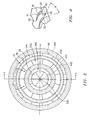
- FIG. 2 shows the body 28 having a central axis 500 and passageways 34A-34C formed as concentric circular rings about a single centerbody portion 35 and aligned with associated air passageways through the manifold.
- Each passageway contains a circumferential array of vanes 36, each vane extending from a leading edge 38 to a trailing edge 39 (FIG. 4) and having pressure and suction sides 40 and 41 (FIG. 4).
- the exemplary vanes extend generally radially, with vane chords angled relative to the longitudinal direction by an angle ⁇ .
- Other passageway and vane configurations are possible.
- the vanes of each passageway may well differ in span, chordlength, shape, angle, or the like amongst the passageways.
- FIG. 3 shows air and fuel flows 200A-C and 202A-D, respectively, entering the body 28 from the manifold 32 and/or upstream thereof.
- the air flows are generally annular, entering inlets to the associated passageways 34A-34C formed in the upstream face 30.
- the fuel flows may enter one or more plenums 44A-44D inboard and/or outboard of the passageways 34A-C.
- Fuel exits the adjacent plenums into the passageways through at least partially radial outlet passageways 46 forming fuel inlets to the passageways 34A-C.
- the fuel mixes with the air to be discharged as mixed fuel/air flows 204A-C.
- Other fueling configurations are possible.
- the vanes function to impart swirl about the axis 500 to the annular fuel/air flows 204A-C.
- the vane configurations and angles ⁇ may be chosen to achieve desired flow properties at one or more desired operating conditions.
- the angles may be of the same sign or of opposite sign (e.g., to create a counter-swirl effect).
- the angles may be of like magnitude or different magnitude. Exemplary angle magnitudes are ⁇ 60°, more narrowly, 10°-50°, and, most particularly, 20°-45°.
- the passageways 34A-C may have different spans. Some may be replaced by other configurations (e.g., rings of drilled passages).
- each passageway may be fueled differently (e.g., as shown in the '311 application).
- Factors such as the swirl magnitude, radial position, and span of the passageways may be optimized in view of available fuel/air ratios to provide advantageous performance at one or more operating conditions.
- An exemplary iterative optimization process may be performed in a reengineering of an existing injector.
- the factors may be iteratively varied.
- the combination of fuel/air ratios may be varied to establish associated operating conditions.
- Performance parameters may be measured at those operating conditions (e.g., efficiency, emissions, and stability).
- the structure and operational parameters associated with desired performance may be noted, with the structure being selected as the reengineered injector configuration and the operational parameters potentially being utilized to configure a control system.
- Optimization may use a figure of merit that includes appropriately weighted emissions parameters (e.g., of NO x , CO, and unburned hydrocarbons (UHC)) and other performance characteristics (e.g., pressure fluctuation levels), resulting in an optimized configuration that gives the best (or at least an acceptable) combined performance based on these metrics.
- the degrees of freedom can be restricted to the fuel staging scheme (i.e., how much fuel flows through each of the passageways given a fixed total fuel flow) or can be extended to include the swirl angles of each of the passageways or the relative air flow rates associated with each of the passageways, based on their relative flow capacities.
- the former is a technique that can be used after the injector is built and can be used to tune the combustor to its best operating point. The latter technique is appropriately used before the final device is built.
- Fueling may be used to create zones of different temperature. Relatively cool zones (e.g., by flame temperature) are associated with off-stoichiometric fuel/air mixtures. Relatively hot zones will be closer to stoichiometric. Cooler zones tend to lack stability. Locating a hotter zone adjacent to a cooler zone may stabilize the cooler zone.
- different fuel/air ratios for the different nozzle rings may create an exemplary three annular combustion zones downstream of the injector: lean, yet relatively hot, outboard and inboard zones; and a leaner and cooler intermediate zone. The outboard and inboard zones provide stability, while the intermediate zone reduces total fuel flow in a low power setting (or range).
- the low temperatures of the intermediate zone will have relatively low NO x .
- desired advantageously low levels of UHC and CO may be achieved.
- Increasing/decreasing the equivalence ratio of the intermediate zone may serve to increase/decrease engine power while maintaining desired stability and low emissions.
- the vanes are configured to permit operation at a condition wherein the outboard and inboard passageways 34A and 34C are run lean (e.g., an equivalence ratio in the vicinity of 0.4-0.7) and the intermediate passageway 34B is run yet leaner and cooler.
- lean e.g., an equivalence ratio in the vicinity of 0.4-0.7
- the intermediate passageway 34B is run yet leaner and cooler.
- This may create an associated three annular combustion zones downstream of the injector: lean outboard and inboard zones; and a leaner intermediate zone.
- the outboard and inboard zones provide stability, while the intermediate zone reduces total fuel flow in a low power setting while still maintaining desired advantageously low levels of UHC and CO.
- different fuel/air mixtures may facilitate altering the spatial distribution of the three zones or may facilitate yet more complex distributions (e.g., a lean trough within an intermediate rich zone to create more of a five-zone system). Two-zone operation is also possible.
- a so-called rich-quench-lean operation introduces additional air downstream to produce lean combustion.
- Such operation may have an intermediate zone exiting the nozzle that is well above stoichiometric and thus also cool.
- the inboard and outboard zones may be closer to stoichiometric (whether lean or rich) and thus hotter and more stable to stabilize the intermediate zone.
- NO x generation is associated with high temperature, the low temperatures of the intermediate zone (through which the majority of fuel may flow) will have relatively low NO x .
- the inboard, and outboard zones may represent a lesser portion of the total fuel (and/or air) flow and thus the increase (if any) of NO x (relative to a uniform distribution of the same total amounts of fuel and air) in these zones may be offset.
- Yet other combinations of hot and cold zones and their absolute and relative fuel/air ratios may be used at least transiently for different combustor configurations and operating conditions.
- the flame may otherwise become unstable at equivalence ratios of about equal to or greater than 1.6 for rich and about equal to or less than 0.5 for lean.
- the cooler zone(s) could be run in these ranges (e.g., more narrowly, 0.1-0.5 or 1.6-5.0).
- the hotter zone(s) could be run between ).5 and 1.6 (e.g., more narrowly 0.5-0.8 or 1.3-1.6, or, yet more narrowly, 0.5 -0.6 or 1.5-1.6; staying away from stoichiometric to avoid high flame temperature and, therefore, reduce NO x formation).
- Other fuels and pressures could be associated with other ranges.
Landscapes
- Engineering & Computer Science (AREA)
- Chemical & Material Sciences (AREA)
- Combustion & Propulsion (AREA)
- Mechanical Engineering (AREA)
- General Engineering & Computer Science (AREA)
- Turbine Rotor Nozzle Sealing (AREA)
Abstract
Description
Claims (18)
- A fuel injector apparatus (26) comprising:a plurality of generally annular passageways (34A...C), the passageways being coaxial about an injector axis (500), each passageway defining a gas flowpath having an inlet for receiving air and an outlet for discharging a fuel/air mixture (204A...C);a plurality of arrays of vanes (36), each array in an associated one of the passageways; anda plurality of fuel flows (202A....C) introducing said fuel to said air.
- A fuel injector apparatus (26) comprising:first means defining a plurality of flowpaths (34A...C) having an inlet for receiving air and an outlet for discharging a fuel/air mixture;one or more arrays of vanes (36), each such array in positioned to impart swirl to an associated one or more of the flowpaths; andsecond means (202A ... D)for introducing said fuel to said air.
- The apparatus of claim 2 comprising a plurality of said arrays.
- The apparatus of claim 2 or 3 wherein:each of at least two of the flowpaths (34A...C) substantially circumscribe an axis (500) of the apparatus.
- The apparatus of claim 2, 3 or 4 wherein:each of at least two of the flowpaths (34A...C) is substantially annular.
- The apparatus of claim 2 to 5 wherein:each of at least two of the flowpaths (34A...C) is substantially concentric with each other.
- The apparatus of any preceding claim wherein:the vanes (36) in a first of said arrays are oriented to provide a first circulation; andthe vanes (36) in a second of said arrays, inboard of said first of said arrays are oriented to provide a second circulation of like sign to the first circulation.
- The apparatus of claim 7 wherein:each of the vanes (36) in the first of the arrays is oriented at a like first relative orientation; andeach of the vanes (36) in the second of the arrays is oriented at a like second relative orientation.
- The apparatus of claim 7 or 8 further comprising:a third of said arrays (36) between the first and second of said arrays.
- The apparatus of any preceding claim operating to provide:a first combustion zone;a second combustion zone inboard of the first and leaner than the first; anda third combustion zone inboard of the second and richer than the second.
- The apparatus of claim 10 wherein the first, second, and third combustion zones are below stoichiometric.
- The apparatus of any preceding claim used with a gas turbine engine combustor (20).
- The apparatus of any preceding claim wherein there are at least ten vanes (36) in at least first and second of the arrays.
- A method for engineering the apparatus of any preceding claim comprising selecting orientations of vanes in first and second of the arrays so as to provide a target level of at least one of:one or more emissions levels; andone or more pressure fluctuation levels.
- The method of claim 14 comprising selecting orientations of vanes (36) in first and second of the arrays so as to provide a target level of both of:said one or more emissions levels; andsaid one or more pressure fluctuation levels.
- The method of claim 14 or 15 wherein the selecting is performed in view of or in combination with fuel/air ratios of the one or more passageways at one or more operating conditions.
- The method of claim 16 wherein the selecting is performed so as to achieve a target stabilization of one or more cool zones by one or more hot zones.
- The method of any of claims 14 to 17 wherein the emissions levels include levels of UHC, CO, and NOX at one or more power levels.
Applications Claiming Priority (2)
| Application Number | Priority Date | Filing Date | Title |
|---|---|---|---|
| US10/843,812 US7350357B2 (en) | 2004-05-11 | 2004-05-11 | Nozzle |
| US843812 | 2004-05-11 |
Publications (2)
| Publication Number | Publication Date |
|---|---|
| EP1596132A1 true EP1596132A1 (en) | 2005-11-16 |
| EP1596132B1 EP1596132B1 (en) | 2012-08-08 |
Family
ID=34941203
Family Applications (1)
| Application Number | Title | Priority Date | Filing Date |
|---|---|---|---|
| EP05252832A Expired - Lifetime EP1596132B1 (en) | 2004-05-11 | 2005-05-09 | Method of operating a fuel injection apparatus |
Country Status (5)
| Country | Link |
|---|---|
| US (1) | US7350357B2 (en) |
| EP (1) | EP1596132B1 (en) |
| JP (1) | JP2005326144A (en) |
| KR (1) | KR20060047369A (en) |
| RU (1) | RU2304741C2 (en) |
Cited By (4)
| Publication number | Priority date | Publication date | Assignee | Title |
|---|---|---|---|---|
| EP1890083A1 (en) * | 2006-08-16 | 2008-02-20 | Siemens Aktiengesellschaft | Fuel injector for a gas turbine engine |
| EP2515041B1 (en) * | 2011-04-21 | 2017-04-05 | General Electric Company | Fuel Nozzle And Method For Operating A Combustor |
| IT201700027637A1 (en) * | 2017-03-13 | 2018-09-13 | Ansaldo Energia Spa | BURNER UNIT FOR A GAS TURBINE SYSTEM FOR THE PRODUCTION OF ELECTRICITY, GAS TURBINE PLANT FOR THE PRODUCTION OF ELECTRIC ENERGY INCLUDING THE BURNER GROUP AND METHOD TO OPERATE THE GAS TURBINE SYSTEM |
| WO2026057340A1 (en) * | 2024-09-16 | 2026-03-19 | Siemens Energy Global GmbH & Co. KG | Pilot burner having premixing arrangement in gas turbine to premix air and fuel at two distinct premixing locations |
Families Citing this family (17)
| Publication number | Priority date | Publication date | Assignee | Title |
|---|---|---|---|---|
| JP4997018B2 (en) * | 2007-08-09 | 2012-08-08 | ゼネラル・エレクトリック・カンパニイ | Pilot mixer for a gas turbine engine combustor mixer assembly having a primary fuel injector and a plurality of secondary fuel injection ports |
| US8220270B2 (en) * | 2008-10-31 | 2012-07-17 | General Electric Company | Method and apparatus for affecting a recirculation zone in a cross flow |
| TWI593878B (en) * | 2010-07-02 | 2017-08-01 | 艾克頌美孚上游研究公司 | Systems and methods for controlling combustion of a fuel |
| JP5464376B2 (en) * | 2011-08-22 | 2014-04-09 | 株式会社日立製作所 | Combustor, gas turbine, and fuel control method for combustor |
| US9644844B2 (en) * | 2011-11-03 | 2017-05-09 | Delavan Inc. | Multipoint fuel injection arrangements |
| US9188063B2 (en) | 2011-11-03 | 2015-11-17 | Delavan Inc. | Injectors for multipoint injection |
| US9291103B2 (en) * | 2012-12-05 | 2016-03-22 | General Electric Company | Fuel nozzle for a combustor of a gas turbine engine |
| CN104696988A (en) * | 2013-12-10 | 2015-06-10 | 中航商用航空发动机有限责任公司 | Combustion chamber of gas turbine and operation method of combustion chamber |
| US10724739B2 (en) | 2017-03-24 | 2020-07-28 | General Electric Company | Combustor acoustic damping structure |
| US10415480B2 (en) | 2017-04-13 | 2019-09-17 | General Electric Company | Gas turbine engine fuel manifold damper and method of dynamics attenuation |
| US11149948B2 (en) | 2017-08-21 | 2021-10-19 | General Electric Company | Fuel nozzle with angled main injection ports and radial main injection ports |
| US11156162B2 (en) | 2018-05-23 | 2021-10-26 | General Electric Company | Fluid manifold damper for gas turbine engine |
| US11506125B2 (en) | 2018-08-01 | 2022-11-22 | General Electric Company | Fluid manifold assembly for gas turbine engine |
| US11149941B2 (en) * | 2018-12-14 | 2021-10-19 | Delavan Inc. | Multipoint fuel injection for radial in-flow swirl premix gas fuel injectors |
| KR102583223B1 (en) | 2022-01-28 | 2023-09-25 | 두산에너빌리티 주식회사 | Nozzle for combustor, combustor, and gas turbine including the same |
| CN115218217B (en) * | 2022-06-16 | 2023-06-16 | 北京航空航天大学 | Main combustion stage head of central staged combustion chamber adopting porous multi-angle oil injection ring structure |
| CN115899771B (en) * | 2022-12-19 | 2024-08-09 | 南京航空航天大学 | Concentric annular swirl combustion chamber for high temperature rise |
Citations (5)
| Publication number | Priority date | Publication date | Assignee | Title |
|---|---|---|---|---|
| US5323614A (en) | 1992-01-13 | 1994-06-28 | Hitachi, Ltd. | Combustor for gas turbine |
| US5713206A (en) * | 1993-04-15 | 1998-02-03 | Westinghouse Electric Corporation | Gas turbine ultra low NOx combustor |
| US5983642A (en) | 1997-10-13 | 1999-11-16 | Siemens Westinghouse Power Corporation | Combustor with two stage primary fuel tube with concentric members and flow regulating |
| US6092363A (en) | 1998-06-19 | 2000-07-25 | Siemens Westinghouse Power Corporation | Low Nox combustor having dual fuel injection system |
| US20040060301A1 (en) | 2002-09-27 | 2004-04-01 | Chen Alexander G. | Multi-point staging strategy for low emission and stable combustion |
Family Cites Families (17)
| Publication number | Priority date | Publication date | Assignee | Title |
|---|---|---|---|---|
| US3938326A (en) | 1974-06-25 | 1976-02-17 | Westinghouse Electric Corporation | Catalytic combustor having a variable temperature profile |
| DE3361535D1 (en) | 1982-05-28 | 1986-01-30 | Bbc Brown Boveri & Cie | Gas turbine combustion chamber and method of operating it |
| SU1688045A2 (en) | 1984-12-29 | 1991-10-30 | Московский энергетический институт | Burner device |
| US5339635A (en) | 1987-09-04 | 1994-08-23 | Hitachi, Ltd. | Gas turbine combustor of the completely premixed combustion type |
| JPH0293210A (en) * | 1988-09-30 | 1990-04-04 | Hitachi Ltd | gas turbine combustor |
| JP2518986Y2 (en) * | 1989-01-20 | 1996-12-04 | 川崎重工業株式会社 | Gas turbine combustor |
| DE4223828A1 (en) | 1992-05-27 | 1993-12-02 | Asea Brown Boveri | Method for operating a combustion chamber of a gas turbine |
| US5289685A (en) | 1992-11-16 | 1994-03-01 | General Electric Company | Fuel supply system for a gas turbine engine |
| RU2050511C1 (en) | 1993-05-19 | 1995-12-20 | Научно-технологический центр энергосберегающих процессов и установок | Method for burning organic fuel |
| US5359847B1 (en) * | 1993-06-01 | 1996-04-09 | Westinghouse Electric Corp | Dual fuel ultra-flow nox combustor |
| DE69431969T2 (en) * | 1993-07-30 | 2003-10-30 | United Technologies Corp., Hartford | Vortex mixing device for a combustion chamber |
| US5394688A (en) | 1993-10-27 | 1995-03-07 | Westinghouse Electric Corporation | Gas turbine combustor swirl vane arrangement |
| JP2954480B2 (en) | 1994-04-08 | 1999-09-27 | 株式会社日立製作所 | Gas turbine combustor |
| JP3673009B2 (en) * | 1996-03-28 | 2005-07-20 | 株式会社東芝 | Gas turbine combustor |
| US6598383B1 (en) | 1999-12-08 | 2003-07-29 | General Electric Co. | Fuel system configuration and method for staging fuel for gas turbines utilizing both gaseous and liquid fuels |
| GB0025765D0 (en) * | 2000-10-20 | 2000-12-06 | Aero & Ind Technology Ltd | Fuel injector |
| JP3986874B2 (en) * | 2001-04-23 | 2007-10-03 | 本田技研工業株式会社 | Fuel injection nozzle for gas turbine |
-
2004
- 2004-05-11 US US10/843,812 patent/US7350357B2/en not_active Expired - Lifetime
-
2005
- 2005-04-22 KR KR1020050033356A patent/KR20060047369A/en not_active Abandoned
- 2005-04-26 JP JP2005127244A patent/JP2005326144A/en active Pending
- 2005-05-09 EP EP05252832A patent/EP1596132B1/en not_active Expired - Lifetime
- 2005-05-11 RU RU2005113955/06A patent/RU2304741C2/en not_active IP Right Cessation
Patent Citations (5)
| Publication number | Priority date | Publication date | Assignee | Title |
|---|---|---|---|---|
| US5323614A (en) | 1992-01-13 | 1994-06-28 | Hitachi, Ltd. | Combustor for gas turbine |
| US5713206A (en) * | 1993-04-15 | 1998-02-03 | Westinghouse Electric Corporation | Gas turbine ultra low NOx combustor |
| US5983642A (en) | 1997-10-13 | 1999-11-16 | Siemens Westinghouse Power Corporation | Combustor with two stage primary fuel tube with concentric members and flow regulating |
| US6092363A (en) | 1998-06-19 | 2000-07-25 | Siemens Westinghouse Power Corporation | Low Nox combustor having dual fuel injection system |
| US20040060301A1 (en) | 2002-09-27 | 2004-04-01 | Chen Alexander G. | Multi-point staging strategy for low emission and stable combustion |
Cited By (6)
| Publication number | Priority date | Publication date | Assignee | Title |
|---|---|---|---|---|
| EP1890083A1 (en) * | 2006-08-16 | 2008-02-20 | Siemens Aktiengesellschaft | Fuel injector for a gas turbine engine |
| EP2515041B1 (en) * | 2011-04-21 | 2017-04-05 | General Electric Company | Fuel Nozzle And Method For Operating A Combustor |
| IT201700027637A1 (en) * | 2017-03-13 | 2018-09-13 | Ansaldo Energia Spa | BURNER UNIT FOR A GAS TURBINE SYSTEM FOR THE PRODUCTION OF ELECTRICITY, GAS TURBINE PLANT FOR THE PRODUCTION OF ELECTRIC ENERGY INCLUDING THE BURNER GROUP AND METHOD TO OPERATE THE GAS TURBINE SYSTEM |
| EP3376110A1 (en) * | 2017-03-13 | 2018-09-19 | Ansaldo Energia S.p.A. | Burner unit for a gas turbine electrical power plant, gas turbine electrical power plant comprising said burner unit and method for operating said gas turbine electrical power plant |
| CN108571747A (en) * | 2017-03-13 | 2018-09-25 | 安萨尔多能源公司 | Burner unit, gas turbine power plant comprising the unit and method of operation thereof |
| WO2026057340A1 (en) * | 2024-09-16 | 2026-03-19 | Siemens Energy Global GmbH & Co. KG | Pilot burner having premixing arrangement in gas turbine to premix air and fuel at two distinct premixing locations |
Also Published As
| Publication number | Publication date |
|---|---|
| JP2005326144A (en) | 2005-11-24 |
| EP1596132B1 (en) | 2012-08-08 |
| RU2304741C2 (en) | 2007-08-20 |
| RU2005113955A (en) | 2006-11-20 |
| US20050252217A1 (en) | 2005-11-17 |
| KR20060047369A (en) | 2006-05-18 |
| US7350357B2 (en) | 2008-04-01 |
Similar Documents
| Publication | Publication Date | Title |
|---|---|---|
| EP1596132B1 (en) | Method of operating a fuel injection apparatus | |
| US10724441B2 (en) | Segmented annular combustion system | |
| EP0747635B1 (en) | Dry low oxides of nitrogen lean premix module for industrial gas turbine engines | |
| US6826913B2 (en) | Airflow modulation technique for low emissions combustors | |
| US8763359B2 (en) | Apparatus for combusting fuel within a gas turbine engine | |
| EP1193449B1 (en) | Multiple annular swirler | |
| US5813232A (en) | Dry low emission combustor for gas turbine engines | |
| US7165405B2 (en) | Fully premixed secondary fuel nozzle with dual fuel capability | |
| US7509811B2 (en) | Multi-point staging strategy for low emission and stable combustion | |
| US7448218B2 (en) | Premix burner and method for burning a low-calorie combustion gas | |
| US20090056336A1 (en) | Gas turbine premixer with radially staged flow passages and method for mixing air and gas in a gas turbine | |
| US20040006991A1 (en) | Fully premixed secondary fuel nozzle with improved stability and dual fuel capability | |
| US20100180599A1 (en) | Insertable Pre-Drilled Swirl Vane for Premixing Fuel Nozzle | |
| US7546740B2 (en) | Nozzle | |
| JP3192055B2 (en) | Gas turbine combustor | |
| US6543231B2 (en) | Cyclone combustor | |
| US20250067436A1 (en) | Ammonia combustor | |
| EP2584267B1 (en) | Injector having multiple fuel pegs |
Legal Events
| Date | Code | Title | Description |
|---|---|---|---|
| PUAI | Public reference made under article 153(3) epc to a published international application that has entered the european phase |
Free format text: ORIGINAL CODE: 0009012 |
|
| AK | Designated contracting states |
Kind code of ref document: A1 Designated state(s): AT BE BG CH CY CZ DE DK EE ES FI FR GB GR HU IE IS IT LI LT LU MC NL PL PT RO SE SI SK TR |
|
| AX | Request for extension of the european patent |
Extension state: AL BA HR LV MK YU |
|
| 17P | Request for examination filed |
Effective date: 20060515 |
|
| AKX | Designation fees paid |
Designated state(s): AT BE BG CH LI |
|
| RBV | Designated contracting states (corrected) |
Designated state(s): DE FR GB IT |
|
| REG | Reference to a national code |
Ref country code: DE Ref legal event code: 8566 |
|
| 17Q | First examination report despatched |
Effective date: 20060720 |
|
| GRAP | Despatch of communication of intention to grant a patent |
Free format text: ORIGINAL CODE: EPIDOSNIGR1 |
|
| RTI1 | Title (correction) |
Free format text: METHOD OF OPERATING A FUEL INJECTION APPARATUS |
|
| GRAS | Grant fee paid |
Free format text: ORIGINAL CODE: EPIDOSNIGR3 |
|
| GRAA | (expected) grant |
Free format text: ORIGINAL CODE: 0009210 |
|
| AK | Designated contracting states |
Kind code of ref document: B1 Designated state(s): DE FR GB IT |
|
| REG | Reference to a national code |
Ref country code: GB Ref legal event code: FG4D |
|
| REG | Reference to a national code |
Ref country code: DE Ref legal event code: R096 Ref document number: 602005035497 Country of ref document: DE Effective date: 20120927 |
|
| PG25 | Lapsed in a contracting state [announced via postgrant information from national office to epo] |
Ref country code: IT Free format text: LAPSE BECAUSE OF FAILURE TO SUBMIT A TRANSLATION OF THE DESCRIPTION OR TO PAY THE FEE WITHIN THE PRESCRIBED TIME-LIMIT Effective date: 20120808 |
|
| PLBE | No opposition filed within time limit |
Free format text: ORIGINAL CODE: 0009261 |
|
| STAA | Information on the status of an ep patent application or granted ep patent |
Free format text: STATUS: NO OPPOSITION FILED WITHIN TIME LIMIT |
|
| 26N | No opposition filed |
Effective date: 20130510 |
|
| REG | Reference to a national code |
Ref country code: DE Ref legal event code: R097 Ref document number: 602005035497 Country of ref document: DE Effective date: 20130510 |
|
| REG | Reference to a national code |
Ref country code: FR Ref legal event code: ST Effective date: 20140131 |
|
| PG25 | Lapsed in a contracting state [announced via postgrant information from national office to epo] |
Ref country code: FR Free format text: LAPSE BECAUSE OF NON-PAYMENT OF DUE FEES Effective date: 20130531 |
|
| REG | Reference to a national code |
Ref country code: DE Ref legal event code: R082 Ref document number: 602005035497 Country of ref document: DE Representative=s name: SCHMITT-NILSON SCHRAUD WAIBEL WOHLFROM PATENTA, DE |
|
| REG | Reference to a national code |
Ref country code: DE Ref legal event code: R082 Ref document number: 602005035497 Country of ref document: DE Representative=s name: SCHMITT-NILSON SCHRAUD WAIBEL WOHLFROM PATENTA, DE Ref country code: DE Ref legal event code: R081 Ref document number: 602005035497 Country of ref document: DE Owner name: UNITED TECHNOLOGIES CORP. (N.D.GES.D. STAATES , US Free format text: FORMER OWNER: UNITED TECHNOLOGIES CORP., HARTFORD, CONN., US |
|
| PGFP | Annual fee paid to national office [announced via postgrant information from national office to epo] |
Ref country code: DE Payment date: 20180419 Year of fee payment: 14 |
|
| PGFP | Annual fee paid to national office [announced via postgrant information from national office to epo] |
Ref country code: GB Payment date: 20180419 Year of fee payment: 14 |
|
| REG | Reference to a national code |
Ref country code: DE Ref legal event code: R119 Ref document number: 602005035497 Country of ref document: DE |
|
| GBPC | Gb: european patent ceased through non-payment of renewal fee |
Effective date: 20190509 |
|
| PG25 | Lapsed in a contracting state [announced via postgrant information from national office to epo] |
Ref country code: DE Free format text: LAPSE BECAUSE OF NON-PAYMENT OF DUE FEES Effective date: 20191203 Ref country code: GB Free format text: LAPSE BECAUSE OF NON-PAYMENT OF DUE FEES Effective date: 20190509 |