EP1596107B1 - Diaphragm valve for vacuum evacuation system - Google Patents
Diaphragm valve for vacuum evacuation system Download PDFInfo
- Publication number
- EP1596107B1 EP1596107B1 EP04709325A EP04709325A EP1596107B1 EP 1596107 B1 EP1596107 B1 EP 1596107B1 EP 04709325 A EP04709325 A EP 04709325A EP 04709325 A EP04709325 A EP 04709325A EP 1596107 B1 EP1596107 B1 EP 1596107B1
- Authority
- EP
- European Patent Office
- Prior art keywords
- diaphragm
- valve seat
- valve
- flow
- passage
- Prior art date
- Legal status (The legal status is an assumption and is not a legal conclusion. Google has not performed a legal analysis and makes no representation as to the accuracy of the status listed.)
- Expired - Fee Related
Links
Images


Classifications
-
- F—MECHANICAL ENGINEERING; LIGHTING; HEATING; WEAPONS; BLASTING
- F16—ENGINEERING ELEMENTS AND UNITS; GENERAL MEASURES FOR PRODUCING AND MAINTAINING EFFECTIVE FUNCTIONING OF MACHINES OR INSTALLATIONS; THERMAL INSULATION IN GENERAL
- F16K—VALVES; TAPS; COCKS; ACTUATING-FLOATS; DEVICES FOR VENTING OR AERATING
- F16K7/00—Diaphragm valves or cut-off apparatus, e.g. with a member deformed, but not moved bodily, to close the passage ; Pinch valves
- F16K7/12—Diaphragm valves or cut-off apparatus, e.g. with a member deformed, but not moved bodily, to close the passage ; Pinch valves with flat, dished, or bowl-shaped diaphragm
- F16K7/14—Diaphragm valves or cut-off apparatus, e.g. with a member deformed, but not moved bodily, to close the passage ; Pinch valves with flat, dished, or bowl-shaped diaphragm arranged to be deformed against a flat seat
- F16K7/16—Diaphragm valves or cut-off apparatus, e.g. with a member deformed, but not moved bodily, to close the passage ; Pinch valves with flat, dished, or bowl-shaped diaphragm arranged to be deformed against a flat seat the diaphragm being mechanically actuated, e.g. by screw-spindle or cam
-
- F—MECHANICAL ENGINEERING; LIGHTING; HEATING; WEAPONS; BLASTING
- F16—ENGINEERING ELEMENTS AND UNITS; GENERAL MEASURES FOR PRODUCING AND MAINTAINING EFFECTIVE FUNCTIONING OF MACHINES OR INSTALLATIONS; THERMAL INSULATION IN GENERAL
- F16K—VALVES; TAPS; COCKS; ACTUATING-FLOATS; DEVICES FOR VENTING OR AERATING
- F16K25/00—Details relating to contact between valve members and seat
- F16K25/005—Particular materials for seats or closure elements
-
- F—MECHANICAL ENGINEERING; LIGHTING; HEATING; WEAPONS; BLASTING
- F16—ENGINEERING ELEMENTS AND UNITS; GENERAL MEASURES FOR PRODUCING AND MAINTAINING EFFECTIVE FUNCTIONING OF MACHINES OR INSTALLATIONS; THERMAL INSULATION IN GENERAL
- F16K—VALVES; TAPS; COCKS; ACTUATING-FLOATS; DEVICES FOR VENTING OR AERATING
- F16K25/00—Details relating to contact between valve members and seat
- F16K25/04—Arrangements for preventing erosion, not otherwise provided for
-
- F—MECHANICAL ENGINEERING; LIGHTING; HEATING; WEAPONS; BLASTING
- F16—ENGINEERING ELEMENTS AND UNITS; GENERAL MEASURES FOR PRODUCING AND MAINTAINING EFFECTIVE FUNCTIONING OF MACHINES OR INSTALLATIONS; THERMAL INSULATION IN GENERAL
- F16K—VALVES; TAPS; COCKS; ACTUATING-FLOATS; DEVICES FOR VENTING OR AERATING
- F16K51/00—Other details not peculiar to particular types of valves or cut-off apparatus
- F16K51/02—Other details not peculiar to particular types of valves or cut-off apparatus specially adapted for high-vacuum installations
Definitions
- the present invention is applicable to, for example, the semiconductor manufacturing equipment. More particularly, the present invention is concerned with improvements in a diaphragm valve to be used in the system for the vacuum exhaustion from a process chamber employed in the semiconductor manufacturing.
- a gas having high chemical reactivity is supplied to the process chamber used in the semiconductor manufacturing facilities and the like. Accordingly, the vacuum exhaustion system for the process chamber is required to exhaust high reactivity gases in safety and with a high degree of efficiency.
- the piping system in the semiconductor manufacturing facilities comprises a system to supply a gas to the process chamber, the process chamber, the vacuum exhaustion system, vacuum pumps, a diaphragm valve and the like.
- vacuum pumps a plural number of pumps, that is, a primary pump (of the high vacuum type) installed immediately after the process chamber and a secondary pump (of the low vacuum type) installed on the secondary side thereof are employed.
- a turbocharged molecular pump is used for the high vacuum type one, while a scroll type pump is used for the low vacuum type one.
- the fluid flow is classified into two regions, i.e., the viscous flow region and the molecular flow region with regard to the relationship between the pressure and the inside diameter of the flow passage.
- the inside diameter D of the flow passage should be L ⁇ D (where L: the mean free path of the gas molecule and D: the inside diameter of the flow passage).
- L the mean free path of the gas molecule
- D the inside diameter of the flow passage.
- the gas is decomposed (or dissociated) when the temperature rises.
- the substances produced by the decomposition of the gas adhere to the inside of the pipings and, as a result, cause the corrosion and the like.
- the decomposition of the gas is caused by catalysis of the metal components of the inner wall of the pipings.
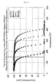
- Figure 3 illustrates, as an example, the relationship between the temperatures and the decomposition of various gases in the case of Spron. As apparent from Figure 3 , the gases which are 100ppm at the room temperature, starts decreasing due to the decomposition along with the rise of the temperature.
- the said diaphragm valve comprises a body provided with a flow-in passage, a flow-out passage, and a valve seat formed between the passages; a diaphragm installed in the body and permitted to rest on and move away from the valve seat; and a driving means installed in the body operating to allow the diaphragm to rest on and move away from the valve seat.
- Patent Literature 1 Japanese Patent No. 3343313
- the problems with this type of valve are as follows. That is, the major constituent components such as the body, the diaphragm and the likes are made of metals. In addition, comparing with the pipings, there are found more curvatures and parts where the gas is retained or trapped with the result that there exist some parts where the pressure and temperature are locally changed. Further, since the inside volume is large, a great amount of gas is likely to be trapped and the inside surface areas are large. As a result, the corrosions, cloggings and valve seat leakages caused by the accumulation (or deposition) and adherence of the substances produced by the thermal decomposition (or thermolysis) of the gas are likely to occur.
- An object of the present invention is to provide a diaphragm valve for the vacuum exhaustion system which can prevent the corrosions caused by the accumulation and adherence of the substances produced by the thermal decomposition of the gas, the cloggings caused by the substances as produced, and the valve seat leakages. It is also an object of the present invention to provide a valve for the vacuum exhaustion system which can make the facilities for the vacuum exhaustion system small-sized and, as a result, lower the costs, and further reduce the diameter of the pipings for the vacuum exhaustion system for shortening the vacuum exhaustion time.
- DE 3540117 discloses a diaphragm valve made of two PTFE layers.
- the diaphragm valve for the vacuum exhaustion system comprises a body having a flow-in passage, a flow-out passage, and a valve seat formed between the passages; a diaphragm installed in the body and permitted to rest on and move away from the valve seat; and a driving means provided on the body to allow the diaphragm to rest on and move away from the valve seat, wherein a synthetic fluorine-contained resin film of a predetermined thickness is coated on the fluid-contacting parts of the afore-mentioned body and diaphragm.
- the parts where the synthetic resin film is coated are the surfaces of the flow-in passage, the flow-out passage and the valve seat, and further the lower side of the diaphragm all of which the fluid is allowed to contact. In this manner, the coating is limited to the parts where the coating is necessary, thus further making it possible to reduce the costs.
- the fluid-contacting parts of the body and diaphragm are coated with the synthetic resin film of the predetermined thickness (thickness of 50 ⁇ 100 ⁇ m), preventing the substances produced by the thermal decomposition of the gas from directly contacting and adhering to the liquid-contacting parts. As a result, the liquid-contacting parts are not corroded.
- the diaphragm When the driving means is operated for closing the valve, the diaphragm is allowed to rest on the valve seat by the elastic deformation of the diaphragm, thus shutting off the flow of the fluid from the flow-in passage to the flow-out passage.
- the diaphragm Conversely, when the driving means is operated for opening the valve, the diaphragm returns to its original shape by self-elasticity and, as a result, moves away from the valve seat, thus allowing the fluid to flow from the flow-in passage to the flow-out passage.
- the diaphragm Since the synthetic resin film of the predetermined thickness is coated on the liquid-contacting parts of the body and diaphragm, the diaphragm is allowed to rest on the valve seat via the fluid-contacting parts, thereby making it possible to for the diaphragm to rest on the valve seat more softly than in the case where the two metal parts are brought into a direct contact with each other. As a result, damages to and abrasion of the valve seat and the diaphragm are prevented.
- the fluorine-contained resin is used.
- polytetrafluoroethylene resin PTFE
- FEP fluorinated ethylene-propylene copolymer
- PFA tetrafluoroethylene-perfluoroalkylevinyl ether copolymer
- Figure 1 is a longitudinal sectional view of a diaphragm valve according to the present invention.
- Figure 2 is a longitudinal sectional view of an enlarged essential part of Figure 1 .
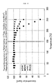
- Figure 3 is a graph to show the relationship between the decomposition and temperatures of various gases where Spron is coated with Teflon.
- a major part of the diaphragm valve 1 comprises a body 2, a diaphragm 3, a driving means 4 and a synthetic resin film 5.
- the diaphragm valve 1 is a normally open, direct touch type valve which is employed between a process chamber and a primary pump, or between the primary pump and a secondary pump in the vacuum exhaustion system.
- the body 2 includes a flow-in passage 6, a flow-out passage 7 and a valve seat 8 formed between the two passages and made of stainless steel (i.e., SUS316L and the like) in this case. That is, the body 2 comprises the flow-in passage 6, the flow-out passage 7, a valve chamber 9 communicating with the passages 6, 7 and formed with an open upper end, and a valve seat 8 provided between the flow-in passage 6 and the flow-out passage 7 in the chamber 9 and extending upward. An end of the flow-in passage 6 opening into the valve chamber 9 is positioned at the center of the body 2.
- the valve seat 8 is formed in a valve seat body 10 which is a separate body from the body 2.
- the valve seat body 10 is made of stainless steel or synthetic resin (for example, polytetrafluoroethlene resin and the like), and includes a holding body 11 made of the same material which works to fix the valve seat body 10 inside the body 2.
- the body 2 is provided with a valve seat body accommodating part 12 which accommodates the valve seat body 10 and a holding body accommodating part 13 which accommodates the holding body 11 and is deeper than the valve seat body accommodating part 12. That is, the valve seat body accommodating part 12 and the holding body accommodating part 13 are formed concentrically at the lower part of the valve chamber 9 of the body 2, centering around the flow-in passage 6.
- the valve seat body 10 is ring-shaped and is provided with an engaging step part 14 formed by cutting off at the upper part of the outer periphery thereof.
- the holding body 11 is ring-shaped and is provided an the engaging step part 15 formed by cutting off at the lower part of the inner periphery thereof to engage with the engaging step part 14.
- the holding body 11 is provided with a plural number (4) of communication bores 16 communicating with the flow-out passage 7 of the body 2.
- the holding body 11 is fitted around the valve seat body 10, and also fitted in the valve chamber 9 of the body 2 and accommodated in the holding body accommodating part 13 of the body 2.
- the diaphragm 3 is provided in the body 2, and allowed to rest on and move away from the valve seat 8.
- the diaphragm 3 made of Spron (austenitic stainless steel) is in the inverted dish shape and is formed of an ultra-thin metal sheet.
- the diaphragm 3 is placed inside the valve chamber 9, keeping the valve chamber 9 air-tight such that the diaphragm 3 is allowed to rest on and move away from the valve seat 8 by elastic deformation in the upward and downward directions.
- the outer periphery of the diaphragm 3 is held between a stainless steel made bonnet 18 and the body 2 with a gasket 17 being placed between the diaphragm 3 and the bonnet 18.
- the bonnet 18 is fixed on the body 2 with a stainless-steel-made bonnet nut 19 screwed on the body 2.
- the driving means 4 is mounted on the body 2 and works to permit the diaphragm 3 to rest on and move away from the valve seat 8.
- the driving means 4 is pneumatically operated.
- the driving means 4 includes a stainless-steel-made stem 20 penetrating through the bonnet 19 and allowed to ascend and descend, and a diaphragm presser 21 made of synthetic resin (for example, polytetrafluoroethylene resin) or synthetic rubber and fitted at the lower end part of the stem 20 to thrust the center part of the diaphragm 3.
- the driving means 4 is further provided with a cylinder 23 having a supply port 22 to supply the air for operation and mounted on the bonnet 19 to surround the upper part of the stem 20, a piston (not illustrated) mounted on the upper part of the stem 22 to slidably ascend and descend inside the cylinder 23, an O-ring (not illustrated) fitted on the outer periphery of the piston for sealing a gap between the piston and the cylinder 23, and a coil spring 24 to urge the stem 20 downward.
- the synthetic resin film 5 is a film of a prescribed thickness with which the fluid-contacting parts 25 of the body 2, the diaphragm 3 and the valve seat body 10 are coated. Teflon (Trade Mark) of 50 ⁇ 100 ⁇ m thick is used for the coating. If the coating were to be thinner than 50 ⁇ m, it would be difficult to prevent the catalytic effects of the metal parts. On the other hand, if the coating were to be thicker than 100 ⁇ m, the liquid flow and the operation of the diaphragm 3 of resting on and moving away from the valve seat 8 would be hindered. Hence, it is important that the coating is 50 - 100 ⁇ m m thick.
- the fluid contacting parts 25 are the surfaces of the flow-in passage 6, the flow-out passage 7, the valve seat 8 (the valve seat body 10 and the holding body 11), and the lower face of the diaphragm 3.
- the film is formed by the method of application and baking.
- the afore-mentioned valve seat body 10 including the holding body 11
- the forming of the afore-mentioned synthetic resin film 5 on the valve seat body 10 is not necessary.
- the synthetic resin film 5 of the predermined thickness is coated on the fluid-contacting parts 25 of the body 2 and the diaphragm 3, the substances produced by the thermal decomposition of gas are not allowed to directly adhere to the fluid-contacting parts 25. This prevents the fluid-contacting parts 25 from being corroded. Also, this makes it possible to make the facilities for the vacuum exhaustion system small-sized, as a result, lower the costs, and, furthermore, reduce the diameter of the vacuum exhaustion pipings for shortening the vacuum exhaustion time. Of course, long life of the diaphragm valve 1 is assured.
- the synthetic resin film 5 of the predetermined thickness is coated on the fluid-contacting parts 25 of the body 2 and the diaphragm 3, the diaphragm 3 is permitted to rest on the valve seat 8 via the fluid-contacting parts 25, thereby making it possible for the diaphragm 3 to rest on the valve seat 8 more softly than in the case where the two metal parts are brought into direct contact with each other. As a result, damages to and abrasion of the valve seat 8 and the diaphragm 3 are prevented.
- Teflon for the synthetic resin film 5 is sufficiently heat resistant approximately up to 150°C against the gases, for example, SiH4 (monosilane), B2H6 (diborane), PH3 (phosphine), AsH3 (arsine) and the like which are used in the semiconductor-related facilities.
- gases for example, SiH4 (monosilane), B2H6 (diborane), PH3 (phosphine), AsH3 (arsine) and the like which are used in the semiconductor-related facilities.
- Figure 3 is a graph to show the relationship between the decomposition (concentration) and the temperatures of various gases used in the semiconductor-related facilities where the outer surface of Spron is coated with Teflon. The graph reveals that there is no decomposition of gases, that is, there is no decrease in the gas concentration even in the event that the temperature exceeds 150°C.
- the body 2 and the diaphragm 3 were made of stainless steel or Spron. However, it is possible that other metal materials can be used to manufacture them.
- the diaphragm 3 is made of a sheet of the ultra-thin meal plate.
- the diaphragm 3 is made of a plural number of ultra-thin metal plates stacked one on another.
- the diaphragm 3 is permitted to directly rest on from the valve seat 8.
- the diaphragm is not limited to this type.
- a disc (not illustrated) can be placed on the lower part of the diaphragm 3 so that the disc is allowed to rest on and move away from the valve seat 8. In this case, it is necessary to urge the disc upward by a spring (not illustrated).
- a disc (not illustrated) is inserted into the a hollow center part of the diaphragm 3, and the inner peripheral part of the diaphragm 3 and the disc are air-tightly fitted and secured to each other so that the afore-mentioned disc is allowed to rest on and move away from the valve seat 8.
- the driving means 4 was pneumatically operated.
- the driving means 4 is not limited to this type.
- a hand-operated method, an electro-magnetic method, a hydraulic method, and the like can be employed instead.
- the synthetic resin film 5 is made of Teflon.
- other synthetic fluorine-contained resin materials can be employed to form the synthetic resin film 5.
- valve seat 8 is formed on the valve seat body 10 which is a separate member from the body 2.
- valve seat 8 is not limited to this type.
- the valve seat can be integrally formed with the body 2.
- the present invention achieves excellent, practical effects as follows:
Description
- The present invention is applicable to, for example, the semiconductor manufacturing equipment. More particularly, the present invention is concerned with improvements in a diaphragm valve to be used in the system for the vacuum exhaustion from a process chamber employed in the semiconductor manufacturing.
- Generally, a gas having high chemical reactivity is supplied to the process chamber used in the semiconductor manufacturing facilities and the like. Accordingly, the vacuum exhaustion system for the process chamber is required to exhaust high reactivity gases in safety and with a high degree of efficiency.
- Normally, the piping system in the semiconductor manufacturing facilities comprises a system to supply a gas to the process chamber, the process chamber, the vacuum exhaustion system, vacuum pumps, a diaphragm valve and the like. For the vacuum pumps, a plural number of pumps, that is, a primary pump (of the high vacuum type) installed immediately after the process chamber and a secondary pump (of the low vacuum type) installed on the secondary side thereof are employed. A turbocharged molecular pump is used for the high vacuum type one, while a scroll type pump is used for the low vacuum type one.
- To effect an efficient exhaustion from the process chamber, it is necessary to employ an exhaustion pump having a high compression ratio which can operate with a high velocity of exhaustion (1/min) even if the suction pressure is low. However, in reality, the vacuum exhaustion pump having a high compression ratio is not easily available. Therefore, in the conventional system for the vacuum exhaustion from the process chamber, in order to deal with two challenges, i.e., one that the gas is to be exhausted with a high degree of efficiency using a pump having a relatively low compression ratio, and the other that the pump overload is to be avoided by keeping small a pressure difference between the primary side and secondary side of the vacuum exhaustion system, the pipings having a large diameter (a nominal diameter of approximately 4 inches) have been employed. For the same reason, the diaphragm valve with a large diameter has been employed.
- The fluid flow is classified into two regions, i.e., the viscous flow region and the molecular flow region with regard to the relationship between the pressure and the inside diameter of the flow passage. To effect an efficient exhaustion, it is required that the exhaustion be conducted in the viscous flow region. To achieve the viscous flow region, the inside diameter D of the flow passage should be L≦D (where L: the mean free path of the gas molecule and D: the inside diameter of the flow passage). There exists the relation, L=4.98 x 10⁻³ /P, between the mean free path of the gas molecule L and the pressure P On the basis of this, the relationship between the pressure and the inside diameter to attain the viscous flow region inside the pipings is obtained. Accordingly, by raising the pressure higher, the mean free path L can be made smaller with the result that the inside diameter D of the pipings to attain the viscous flow region is made small.
- However, as stated above, with the conventional pump having a comparatively small compression ratio (approximately 10), it is not possible to raise the pressure on the discharge outlet side. For example, if the pressure on the chamber side (the intake inlet side) is 10-3 Torr, the discharge outlet side pressure becomes as low as approximately 10-2 Torr. This means that the pipings having an inside diameter of 5cm or more are required to attain the viscous flow region with more certainty. As a result, with the conventional vacuum exhaustion system, there is a problem that since the piping system having a large diameter is required, the facilities are made large-sized. Further, there is another problem that since a larger inside diameter of the vacuum pipe system means a larger volume inside the pipe, it takes a longer time for the vacuum exhaustion Furthermore, to effect the exhaustion operation efficiently in a short time by the vacuum exhaustion system, an expensive vacuum pump having a large compression ratio and a high velocity of exhaustion is needed.
- In recent years, however, the pump having high performance capabilities, or specifically, one which realizes a high compression ratio of approximately 103~104 has been developed. As a result, it is now possible to increase the discharge side pressure of the primary pump to approximately 30~50Torr even when the internal pressure of the process chamber is around 10-3 Torr. Accordingly, by optimizing the pressure conditions of the process chamber and the vacuum exhaustion system, it is now possible to secure the viscous flow region in the pipings having a small diameter of approximately 0.5cm.
- However, if the pressure is raised as mentioned above, moisture or gas condenses in the vacuum exhaustion piping system and adheres to the inside of the pipings.
- Further, even if the condensation and adherence of water, moisture or gas caused by the pressure rise do not occur, the decomposition of the gas remaining inside the pipings happens when the vacuum pump is out of operation. As a result, substances produced by the gas decomposition accumulates inside the pipings and piping parts of the valve, causing the corrosion of the parts, the clogging of the valves by the substances as produced and the valve seat leakages.
- To solve such problems, it is required to keep the inside of the piping system lower than the saturated vapor pressure of gas, water or moisture therein. Hence, it is a common practice, with the vacuum exhaustion system, to effect heating (baking). (In the case of water, the saturated vapor pressure is 17.53Torr at 20°C.) That is, when the temperature is raised by the heating, the saturated vapor pressure rises, making it difficult for the condensation and adherence of water, moisture or gas to occur with the result that the risk of the corrosion and cloggings is reduced. It is known that it is desirable to raise the temperature to approximately 150°C, considering the type of the gas inside the vacuum exhaustion system.
- However, the gas is decomposed (or dissociated) when the temperature rises. Here occurs another problem that the substances produced by the decomposition of the gas adhere to the inside of the pipings and, as a result, cause the corrosion and the like.
- The decomposition of the gas is caused by catalysis of the metal components of the inner wall of the pipings.
Figure 3 illustrates, as an example, the relationship between the temperatures and the decomposition of various gases in the case of Spron. As apparent fromFigure 3 , the gases which are 100ppm at the room temperature, starts decreasing due to the decomposition along with the rise of the temperature. - In the system for the vacuum exhaustion of the process chamber, a direct touch type metal diaphragm valve is commonly used as, for example, shown in the
Patent Literature 1. - Basically, the said diaphragm valve comprises a body provided with a flow-in passage, a flow-out passage, and a valve seat formed between the passages; a diaphragm installed in the body and permitted to rest on and move away from the valve seat; and a driving means installed in the body operating to allow the diaphragm to rest on and move away from the valve seat.
- [Patent Literature 1] Japanese Patent No.
3343313 - The problems with this type of valve are as follows. That is, the major constituent components such as the body, the diaphragm and the likes are made of metals. In addition, comparing with the pipings, there are found more curvatures and parts where the gas is retained or trapped with the result that there exist some parts where the pressure and temperature are locally changed. Further, since the inside volume is large, a great amount of gas is likely to be trapped and the inside surface areas are large. As a result, the corrosions, cloggings and valve seat leakages caused by the accumulation (or deposition) and adherence of the substances produced by the thermal decomposition (or thermolysis) of the gas are likely to occur.
- The present invention has been created to solve the above mentioned problems. An object of the present invention is to provide a diaphragm valve for the vacuum exhaustion system which can prevent the corrosions caused by the accumulation and adherence of the substances produced by the thermal decomposition of the gas, the cloggings caused by the substances as produced, and the valve seat leakages. It is also an object of the present invention to provide a valve for the vacuum exhaustion system which can make the facilities for the vacuum exhaustion system small-sized and, as a result, lower the costs, and further reduce the diameter of the pipings for the vacuum exhaustion system for shortening the vacuum exhaustion time.
-
DE 3540117 discloses a diaphragm valve made of two PTFE layers. - The diaphragm valve for the vacuum exhaustion system according to the present invention comprises a body having a flow-in passage, a flow-out passage, and a valve seat formed between the passages; a diaphragm installed in the body and permitted to rest on and move away from the valve seat; and a driving means provided on the body to allow the diaphragm to rest on and move away from the valve seat, wherein a synthetic fluorine-contained resin film of a predetermined thickness is coated on the fluid-contacting parts of the afore-mentioned body and diaphragm. The parts where the synthetic resin film is coated are the surfaces of the flow-in passage, the flow-out passage and the valve seat, and further the lower side of the diaphragm all of which the fluid is allowed to contact. In this manner, the coating is limited to the parts where the coating is necessary, thus further making it possible to reduce the costs. The fluid-contacting parts of the body and diaphragm are coated with the synthetic resin film of the predetermined thickness (thickness of 50 ∼ 100 µm), preventing the substances produced by the thermal decomposition of the gas from directly contacting and adhering to the liquid-contacting parts. As a result, the liquid-contacting parts are not corroded.
- When the driving means is operated for closing the valve, the diaphragm is allowed to rest on the valve seat by the elastic deformation of the diaphragm, thus shutting off the flow of the fluid from the flow-in passage to the flow-out passage.
- Conversely, when the driving means is operated for opening the valve, the diaphragm returns to its original shape by self-elasticity and, as a result, moves away from the valve seat, thus allowing the fluid to flow from the flow-in passage to the flow-out passage.
- Since the synthetic resin film of the predetermined thickness is coated on the liquid-contacting parts of the body and diaphragm, the diaphragm is allowed to rest on the valve seat via the fluid-contacting parts, thereby making it possible to for the diaphragm to rest on the valve seat more softly than in the case where the two metal parts are brought into a direct contact with each other. As a result, damages to and abrasion of the valve seat and the diaphragm are prevented.
- For the synthetic resin film, the fluorine-contained resin is used. In particular, polytetrafluoroethylene resin (PTFE), fluorinated ethylene-propylene copolymer (FEP), tetrafluoroethylene-perfluoroalkylevinyl ether copolymer (PFA) are preferred. With this construction, the manufacturing can be made easy because the widely-used common products can be employed, thus reducing the costs.
-
-
Figure 1 is a longitudinal sectional view of a diaphragm valve according to the present invention. -
Figure 2 is a longitudinal sectional view of an enlarged essential part ofFigure 1 . -
Figure 3 is a graph to show the relationship between the decomposition and temperatures of various gases where Spron is coated with Teflon. -
Figure 4 is a graph to show the relationship between the decomposition and temperatures of various gases where Spron is employed. -
- 1
- a diaphragm valve
- 2
- a body
- 3
- a diaphragm
- 4
- a driving means
- 5
- a synthetic resin film
- 6
- a flow-in passage
- 7
- a flow-out passage
- 8
- a valve seat
- 9
- a valve chamber
- 10
- a valve seat body
- 11
- a holding body
- 12
- a valve seat body accommodating part
- 13
- a holding body accommodating part
- 14
- an engaging step part
- 15
- an engaging step part
- 16
- a communication bore
- 17
- a gasket
- 18
- a bonnet
- 19
- a bonnet nut
- 20
- a stem .
- 21
- a diaphragm presser
- 22
- a supply port
- 23
- a cylinder
- 24
- a coil spring
- 25
- a fluid-contacting part
- The embodiment in accordance with the present invention is described hereunder with reference to the drawings.
-
Figure 1 is a longitudinal sectional view of a diaphragm valve according to the present invention.Figure 2 is a longitudinal sectional view of an enlarged essential part ofFigure 1 .Figure 3 is a graph to show the relationship between the decomposition and temperatures of various gases where Spron is coated with Teflon. - A major part of the
diaphragm valve 1 comprises abody 2, adiaphragm 3, a driving means 4 and asynthetic resin film 5. Thediaphragm valve 1 is a normally open, direct touch type valve which is employed between a process chamber and a primary pump, or between the primary pump and a secondary pump in the vacuum exhaustion system. - The
body 2 includes a flow-inpassage 6, a flow-outpassage 7 and avalve seat 8 formed between the two passages and made of stainless steel (i.e., SUS316L and the like) in this case. That is, thebody 2 comprises the flow-inpassage 6, the flow-outpassage 7, avalve chamber 9 communicating with thepassages valve seat 8 provided between the flow-inpassage 6 and the flow-outpassage 7 in thechamber 9 and extending upward. An end of the flow-inpassage 6 opening into thevalve chamber 9 is positioned at the center of thebody 2. - The
valve seat 8 is formed in avalve seat body 10 which is a separate body from thebody 2. Thevalve seat body 10 is made of stainless steel or synthetic resin (for example, polytetrafluoroethlene resin and the like), and includes a holdingbody 11 made of the same material which works to fix thevalve seat body 10 inside thebody 2. - The
body 2 is provided with a valve seatbody accommodating part 12 which accommodates thevalve seat body 10 and a holdingbody accommodating part 13 which accommodates the holdingbody 11 and is deeper than the valve seatbody accommodating part 12. That is, the valve seatbody accommodating part 12 and the holdingbody accommodating part 13 are formed concentrically at the lower part of thevalve chamber 9 of thebody 2, centering around the flow-inpassage 6. - The
valve seat body 10 is ring-shaped and is provided with an engagingstep part 14 formed by cutting off at the upper part of the outer periphery thereof. - The holding
body 11 is ring-shaped and is provided an theengaging step part 15 formed by cutting off at the lower part of the inner periphery thereof to engage with the engagingstep part 14. The holdingbody 11 is provided with a plural number (4) of communication bores 16 communicating with the flow-outpassage 7 of thebody 2. - Thus, the holding
body 11 is fitted around thevalve seat body 10, and also fitted in thevalve chamber 9 of thebody 2 and accommodated in the holdingbody accommodating part 13 of thebody 2. - The
diaphragm 3 is provided in thebody 2, and allowed to rest on and move away from thevalve seat 8. In this example, thediaphragm 3 made of Spron (austenitic stainless steel) is in the inverted dish shape and is formed of an ultra-thin metal sheet. Thediaphragm 3 is placed inside thevalve chamber 9, keeping thevalve chamber 9 air-tight such that thediaphragm 3 is allowed to rest on and move away from thevalve seat 8 by elastic deformation in the upward and downward directions. - The outer periphery of the
diaphragm 3 is held between a stainless steel madebonnet 18 and thebody 2 with agasket 17 being placed between thediaphragm 3 and thebonnet 18. Thebonnet 18 is fixed on thebody 2 with a stainless-steel-madebonnet nut 19 screwed on thebody 2. - The driving means 4 is mounted on the
body 2 and works to permit thediaphragm 3 to rest on and move away from thevalve seat 8. In this example, the driving means 4 is pneumatically operated. The driving means 4 includes a stainless-steel-madestem 20 penetrating through thebonnet 19 and allowed to ascend and descend, and adiaphragm presser 21 made of synthetic resin (for example, polytetrafluoroethylene resin) or synthetic rubber and fitted at the lower end part of thestem 20 to thrust the center part of thediaphragm 3. The driving means 4 is further provided with acylinder 23 having asupply port 22 to supply the air for operation and mounted on thebonnet 19 to surround the upper part of thestem 20, a piston (not illustrated) mounted on the upper part of thestem 22 to slidably ascend and descend inside thecylinder 23, an O-ring (not illustrated) fitted on the outer periphery of the piston for sealing a gap between the piston and thecylinder 23, and acoil spring 24 to urge thestem 20 downward. - The
synthetic resin film 5 is a film of a prescribed thickness with which the fluid-contactingparts 25 of thebody 2, thediaphragm 3 and thevalve seat body 10 are coated. Teflon (Trade Mark) of 50 ~ 100µm thick is used for the coating. If the coating were to be thinner than 50µm, it would be difficult to prevent the catalytic effects of the metal parts. On the other hand, if the coating were to be thicker than 100µm, the liquid flow and the operation of thediaphragm 3 of resting on and moving away from thevalve seat 8 would be hindered. Hence, it is important that the coating is 50 - 100µm m thick. Thefluid contacting parts 25 are the surfaces of the flow-inpassage 6, the flow-outpassage 7, the valve seat 8 (thevalve seat body 10 and the holding body 11), and the lower face of thediaphragm 3. - Any method can be used to coat the
synthetic resin film 5. With the present embodiment, the film is formed by the method of application and baking. Needless to say, in the event that the afore-mentioned valve seat body 10 (including the holding body 11) is made of fluorine-contained resin, the forming of the afore-mentionedsynthetic resin film 5 on thevalve seat body 10 is not necessary. - Next, operation of the present invention constructed as mentioned above is described hereunder.
- When the driving means 4 is operated to make the piston and the
stem 20 descend, the center part of thediaphragm 3 is pushed downward by thestem 20, and rests on thevalve seat 8, thus blocking the communication between the flow-inpassage 6 and the flow-outpassage 7 to bring the valve closing state. - Conversely, when the driving means 4 is operated to make the piston and the
stem 20 ascend, thediaphragm 3 returns to the original shape due to self-elasticity and the fluid pressure in thebody 2 so that the diaphragm moves away from thevalve seat 8 to open the communication between the flow-inpassage 6 and the flow-outpassage 7 to bring the valve opening state. - Since the
synthetic resin film 5 of the predermined thickness is coated on the fluid-contactingparts 25 of thebody 2 and thediaphragm 3, the substances produced by the thermal decomposition of gas are not allowed to directly adhere to the fluid-contactingparts 25. This prevents the fluid-contactingparts 25 from being corroded. Also, this makes it possible to make the facilities for the vacuum exhaustion system small-sized, as a result, lower the costs, and, furthermore, reduce the diameter of the vacuum exhaustion pipings for shortening the vacuum exhaustion time. Of course, long life of thediaphragm valve 1 is assured. - Since the
synthetic resin film 5 of the predetermined thickness is coated on the fluid-contactingparts 25 of thebody 2 and thediaphragm 3, thediaphragm 3 is permitted to rest on thevalve seat 8 via the fluid-contactingparts 25, thereby making it possible for thediaphragm 3 to rest on thevalve seat 8 more softly than in the case where the two metal parts are brought into direct contact with each other. As a result, damages to and abrasion of thevalve seat 8 and thediaphragm 3 are prevented. - Teflon for the
synthetic resin film 5 is sufficiently heat resistant approximately up to 150°C against the gases, for example, SiH4 (monosilane), B2H6 (diborane), PH3 (phosphine), AsH3 (arsine) and the like which are used in the semiconductor-related facilities. -
Figure 3 is a graph to show the relationship between the decomposition (concentration) and the temperatures of various gases used in the semiconductor-related facilities where the outer surface of Spron is coated with Teflon. The graph reveals that there is no decomposition of gases, that is, there is no decrease in the gas concentration even in the event that the temperature exceeds 150°C. - In this example, the
body 2 and thediaphragm 3 were made of stainless steel or Spron. However, it is possible that other metal materials can be used to manufacture them. - In this example, the
diaphragm 3 is made of a sheet of the ultra-thin meal plate. However, it is also possible that thediaphragm 3 is made of a plural number of ultra-thin metal plates stacked one on another. - In this example, the
diaphragm 3 is permitted to directly rest on from thevalve seat 8. However, the diaphragm is not limited to this type. For instance, a disc (not illustrated) can be placed on the lower part of thediaphragm 3 so that the disc is allowed to rest on and move away from thevalve seat 8. In this case, it is necessary to urge the disc upward by a spring (not illustrated). It is also possible that a disc (not illustrated) is inserted into the a hollow center part of thediaphragm 3, and the inner peripheral part of thediaphragm 3 and the disc are air-tightly fitted and secured to each other so that the afore-mentioned disc is allowed to rest on and move away from thevalve seat 8. - In this example, the driving means 4 was pneumatically operated. However, the driving means 4 is not limited to this type. For example, a hand-operated method, an electro-magnetic method, a hydraulic method, and the like can be employed instead.
- In this example, the
synthetic resin film 5 is made of Teflon. However, other synthetic fluorine-contained resin materials can be employed to form thesynthetic resin film 5. - In this example, the
valve seat 8 is formed on thevalve seat body 10 which is a separate member from thebody 2. However, thevalve seat 8 is not limited to this type. For instance, the valve seat can be integrally formed with thebody 2. - As stated above, the present invention achieves excellent, practical effects as follows:
- (1) The valve is provided with the body, the diaphragm, the driving means and the synthetic fluorine-contained resin films. In particular, the fluid- contacting parts of the body and the diaphragm are coated with the synthetic fluorine-contained resin films of the predetermined thickness (50-100µm), thereby making it possible to completely prevent the dissociation (decomposition) of the gas. As a result, it is possible to prevent the corrosions of the valve members caused by the accumulation and adherence of the substances as produced by the thermal decomposition, the cloggings caused by the substances as produced, and the seat leakages.
- (2) Since the thermal decomposition is prevented, it is possible to make the facilities for the vacuum exhaustion system small-sized, and, as a result, to lower the costs. It is also possible to reduce the diameter of the vacuum exhaustion system pipings for shortening the vacuum exhaustion time.
Claims (2)
- A diaphragm valve for a vacuum exhaustion system, the valve comprising a body (2) having a flow-in passage (6), a flow-out passage (7) and a valve seat (8) formed between the passages; a diaphragm (3) installed in the body and permitted to rest on and move away from the valve seat; and a driving means (4) provided on the body to allow the diaphragm to rest on and move away from the valve seat, wherein synthetic fluorine-contained resin films of a predetermined thickness are coated on the fluid-contacting parts of the afore-mentioned body and diaphragm, wherein the fluid-contacting parts are surfaces of the flow-in passage, flow-out passage and the valve seat of the body, and also the lower surface of the diaphragm, characterised in that the predetermined thickness is between 50 and 100µm.
- A diaphragm valve as claimed in Claim 1 wherein the synthetic fluorine-contained resin is polytetrafluoroethylene resin (PTFE), fluorinated ethylene-propylene copolymer (FEP) or tetrafluoroethylene-perfluoroalkylevinyl ether copolymer (PFA).
Applications Claiming Priority (3)
| Application Number | Priority Date | Filing Date | Title |
|---|---|---|---|
| JP2003039541A JP4119275B2 (en) | 2003-02-18 | 2003-02-18 | Diaphragm valve for vacuum exhaust system |
| JP2003039541 | 2003-02-18 | ||
| PCT/JP2004/001346 WO2004074722A1 (en) | 2003-02-18 | 2004-02-09 | Diaphragm valve for vacuum evacuation system |
Publications (3)
| Publication Number | Publication Date |
|---|---|
| EP1596107A1 EP1596107A1 (en) | 2005-11-16 |
| EP1596107A4 EP1596107A4 (en) | 2006-05-17 |
| EP1596107B1 true EP1596107B1 (en) | 2008-07-23 |
Family
ID=32905174
Family Applications (1)
| Application Number | Title | Priority Date | Filing Date |
|---|---|---|---|
| EP04709325A Expired - Fee Related EP1596107B1 (en) | 2003-02-18 | 2004-02-09 | Diaphragm valve for vacuum evacuation system |
Country Status (9)
| Country | Link |
|---|---|
| US (1) | US7416165B2 (en) |
| EP (1) | EP1596107B1 (en) |
| JP (1) | JP4119275B2 (en) |
| KR (1) | KR100673399B1 (en) |
| CN (1) | CN100376829C (en) |
| DE (1) | DE602004015250D1 (en) |
| IL (1) | IL169383A (en) |
| TW (1) | TWI285716B (en) |
| WO (1) | WO2004074722A1 (en) |
Families Citing this family (42)
| Publication number | Priority date | Publication date | Assignee | Title |
|---|---|---|---|---|
| EP1794581A2 (en) | 2004-09-15 | 2007-06-13 | Microchip Biotechnologies, Inc. | Microfluidic devices |
| JP2006153230A (en) * | 2004-12-01 | 2006-06-15 | Neriki:Kk | Diaphragm for fluid controller and valve device using the same |
| WO2006083783A1 (en) * | 2005-01-31 | 2006-08-10 | Swagelok Company | Flow control device |
| JP5063616B2 (en) | 2006-02-03 | 2012-10-31 | インテジェニックス インコーポレイテッド | Microfluidic device |
| CN101715483A (en) | 2007-02-05 | 2010-05-26 | 微芯片生物工艺学股份有限公司 | microfluidic and nanofluidic devices, systems, and applications |
| US8434793B2 (en) * | 2007-07-19 | 2013-05-07 | Swagelok Company | Coated seals |
| US20090114873A1 (en) * | 2007-11-05 | 2009-05-07 | Richard Anagnos | Diaphragm for use with control valves |
| WO2009108260A2 (en) | 2008-01-22 | 2009-09-03 | Microchip Biotechnologies, Inc. | Universal sample preparation system and use in an integrated analysis system |
| JP5319942B2 (en) * | 2008-03-18 | 2013-10-16 | 大日本スクリーン製造株式会社 | Diaphragm valve and substrate processing apparatus provided with the same |
| US8672532B2 (en) | 2008-12-31 | 2014-03-18 | Integenx Inc. | Microfluidic methods |
| CN102459565A (en) | 2009-06-02 | 2012-05-16 | 尹特根埃克斯有限公司 | Fluidic devices with diaphragm valves |
| US8794595B2 (en) * | 2009-07-27 | 2014-08-05 | Merck Sharp & Dohme Corp. | Diaphragm valve with improved sealing performance and leak detection |
| US8584703B2 (en) * | 2009-12-01 | 2013-11-19 | Integenx Inc. | Device with diaphragm valve |
| KR101088679B1 (en) | 2010-05-10 | 2011-12-01 | 주식회사 원익아이피에스 | Apparatus and method for processing substrate |
| US8512538B2 (en) | 2010-05-28 | 2013-08-20 | Integenx Inc. | Capillary electrophoresis device |
| US8763642B2 (en) | 2010-08-20 | 2014-07-01 | Integenx Inc. | Microfluidic devices with mechanically-sealed diaphragm valves |
| US9121058B2 (en) | 2010-08-20 | 2015-09-01 | Integenx Inc. | Linear valve arrays |
| JP5331180B2 (en) * | 2011-09-22 | 2013-10-30 | 株式会社フジキン | Valve stroke adjustment method for direct touch type metal diaphragm valve |
| JP5802532B2 (en) * | 2011-12-05 | 2015-10-28 | 株式会社フジキン | Diaphragm valve and seat holder unit for diaphragm valve |
| JP2013119877A (en) * | 2011-12-06 | 2013-06-17 | Fujikin Inc | Diaphragm valve |
| JP5964139B2 (en) * | 2012-05-30 | 2016-08-03 | 株式会社フジキン | Diaphragm and diaphragm valve |
| WO2014141358A1 (en) * | 2013-03-11 | 2014-09-18 | 株式会社島津製作所 | Flow path switching valve |
| US9454158B2 (en) | 2013-03-15 | 2016-09-27 | Bhushan Somani | Real time diagnostics for flow controller systems and methods |
| JP6072648B2 (en) * | 2013-08-12 | 2017-02-01 | 株式会社フジキン | Diaphragm valve |
| JP6530929B2 (en) * | 2015-02-27 | 2019-06-12 | 株式会社フジキン | Fluid controller |
| KR101727624B1 (en) | 2015-05-14 | 2017-04-17 | 한국과학기술원 | Microfluidic valve |
| JP6516696B2 (en) * | 2016-03-01 | 2019-05-22 | 株式会社鷺宮製作所 | Volume adjustment valve |
| JP6307557B2 (en) * | 2016-06-17 | 2018-04-04 | Ckd株式会社 | Fluid control valve |
| FR3054609A1 (en) * | 2016-07-29 | 2018-02-02 | Plastic Omnium Advanced Innovation & Res | VENTILATION FLOW REGULATOR FOR A PRESSURIZED VEHICLE TANK. |
| JP6914044B2 (en) * | 2017-01-31 | 2021-08-04 | 株式会社キッツエスシーティー | Diaphragm valve |
| US10983537B2 (en) | 2017-02-27 | 2021-04-20 | Flow Devices And Systems Inc. | Systems and methods for flow sensor back pressure adjustment for mass flow controller |
| KR101905104B1 (en) * | 2017-03-09 | 2018-10-11 | (주)씨에스이 | Air pump equipped with diaphragm |
| JP6929098B2 (en) * | 2017-03-30 | 2021-09-01 | 株式会社キッツエスシーティー | Metal diaphragm valve |
| JP7045839B2 (en) * | 2017-12-08 | 2022-04-01 | 株式会社キッツエスシーティー | Fluid control valve |
| JP6945859B2 (en) * | 2018-06-04 | 2021-10-06 | 株式会社不二工機 | Flow switching valve |
| CN109667955B (en) * | 2018-12-13 | 2024-03-29 | 江西增鑫科技股份有限公司 | Diaphragm valve and method for conveying fluid by adopting diaphragm valve |
| WO2020250316A1 (en) * | 2019-06-11 | 2020-12-17 | 株式会社島津製作所 | Back pressure control valve |
| KR20220029730A (en) * | 2019-08-30 | 2022-03-08 | 가부시키가이샤 후지킨 | diaphragm valve |
| JP7401896B2 (en) | 2019-10-29 | 2023-12-20 | 株式会社フジキン | valve |
| KR20220140821A (en) * | 2020-03-26 | 2022-10-18 | 가부시키가이샤 후지킨 | valve device |
| JP2022047691A (en) * | 2020-09-14 | 2022-03-25 | 株式会社堀場エステック | Fluid control valve and fluid control device |
| JP7461686B2 (en) | 2021-04-01 | 2024-04-04 | 株式会社フジキン | Controller and vaporizer |
Family Cites Families (26)
| Publication number | Priority date | Publication date | Assignee | Title |
|---|---|---|---|---|
| US2406963A (en) * | 1943-08-16 | 1946-09-03 | Thompson Prod Inc | Valve seat insert assembly, and assembly method and means |
| GB955411A (en) * | 1959-02-25 | 1964-04-15 | Saunders Valve Co Ltd | Improvements in and relating to valves for the control of fluids |
| US3487823A (en) * | 1967-07-31 | 1970-01-06 | Carl M Tarter | Composite valve seat insert and method of overhaul |
| US3750698A (en) * | 1970-07-16 | 1973-08-07 | Xerox Corp | Coated valving member |
| US4337144A (en) * | 1980-05-19 | 1982-06-29 | Atlantic Richfield Company | Aluminum passivation process |
| US4317713A (en) * | 1980-05-19 | 1982-03-02 | Atlantic Richfield Company | In situ aluminum passivation process |
| US4538638A (en) * | 1984-03-08 | 1985-09-03 | The Dow Chemical Company | Plastic lined diaphragm valve |
| JPS62107216A (en) * | 1985-11-05 | 1987-05-18 | Ngk Insulators Ltd | Valve seat insert and cylinder head comprising same |
| DE3546117C1 (en) * | 1985-12-24 | 1987-02-12 | Resistoflex Gmbh | Two-layer diaphragm for a diaphragm valve |
| US5127430A (en) * | 1990-02-01 | 1992-07-07 | Industrial Ceramics Engineering | Ceramic weir for valve body |
| DE4231343A1 (en) * | 1992-09-18 | 1994-03-24 | Mueller Apparatebau Gmbh & Co | Plastic body |
| US5658452A (en) * | 1994-01-04 | 1997-08-19 | Chevron Chemical Company | Increasing production in hydrocarbon conversion processes |
| US5413311A (en) * | 1994-03-01 | 1995-05-09 | Tescom Corporation | Gas valve |
| JP3343313B2 (en) * | 1995-06-30 | 2002-11-11 | 株式会社フジキン | Diaphragm valve |
| JPH102452A (en) * | 1996-06-14 | 1998-01-06 | Smc Corp | High vacuum valve |
| FR2759759B1 (en) * | 1997-02-17 | 1999-05-21 | Asm France Sa | BLINDING DEVICE FOR MEMBRANE VALVE |
| JP4146535B2 (en) | 1997-10-20 | 2008-09-10 | 忠弘 大見 | Constant displacement fluid controller |
| CN1111661C (en) * | 1998-10-15 | 2003-06-18 | 株式会社富士金 | Fluid controller |
| US6321776B1 (en) * | 2000-04-24 | 2001-11-27 | Wayne L. Pratt | Double diaphragm precision throttling valve |
| EP1300619B1 (en) * | 2000-06-05 | 2006-08-02 | Fujikin Incorporated | Orifice-built-in valve |
| US6409149B1 (en) * | 2000-06-28 | 2002-06-25 | Mks Instruments, Inc. | Dual pendulum valve assembly with valve seat cover |
| JP3686007B2 (en) * | 2001-04-23 | 2005-08-24 | 株式会社巴技術研究所 | Method for manufacturing a butterfly valve disc |
| JP2003166660A (en) | 2001-11-30 | 2003-06-13 | Ckd Corp | Fluid control valve |
| JP3995543B2 (en) * | 2002-07-03 | 2007-10-24 | 旭有機材工業株式会社 | Fluid control valve |
| US6904935B2 (en) * | 2002-12-18 | 2005-06-14 | Masco Corporation Of Indiana | Valve component with multiple surface layers |
| US6941963B2 (en) * | 2003-06-26 | 2005-09-13 | Planar Systems, Inc. | High-speed diaphragm valve for atomic layer deposition |
-
2003
- 2003-02-18 JP JP2003039541A patent/JP4119275B2/en not_active Expired - Lifetime
-
2004
- 2004-02-09 WO PCT/JP2004/001346 patent/WO2004074722A1/en active IP Right Grant
- 2004-02-09 CN CNB2004800044663A patent/CN100376829C/en not_active Expired - Fee Related
- 2004-02-09 EP EP04709325A patent/EP1596107B1/en not_active Expired - Fee Related
- 2004-02-09 KR KR1020057013029A patent/KR100673399B1/en active IP Right Grant
- 2004-02-09 US US10/546,032 patent/US7416165B2/en active Active
- 2004-02-09 DE DE602004015250T patent/DE602004015250D1/de not_active Expired - Fee Related
- 2004-02-17 TW TW093103762A patent/TWI285716B/en active
-
2005
- 2005-06-23 IL IL169383A patent/IL169383A/en not_active IP Right Cessation
Also Published As
| Publication number | Publication date |
|---|---|
| US20060175573A1 (en) | 2006-08-10 |
| KR100673399B1 (en) | 2007-01-24 |
| TWI285716B (en) | 2007-08-21 |
| TW200422547A (en) | 2004-11-01 |
| CN100376829C (en) | 2008-03-26 |
| US7416165B2 (en) | 2008-08-26 |
| JP4119275B2 (en) | 2008-07-16 |
| WO2004074722A1 (en) | 2004-09-02 |
| IL169383A (en) | 2008-03-20 |
| CN1751196A (en) | 2006-03-22 |
| EP1596107A4 (en) | 2006-05-17 |
| EP1596107A1 (en) | 2005-11-16 |
| JP2004263576A (en) | 2004-09-24 |
| DE602004015250D1 (en) | 2008-09-04 |
| KR20050095611A (en) | 2005-09-29 |
Similar Documents
| Publication | Publication Date | Title |
|---|---|---|
| EP1596107B1 (en) | Diaphragm valve for vacuum evacuation system | |
| US7988130B2 (en) | Valve for vacuum exhaustion system | |
| US5462080A (en) | Heated removable throttle valve | |
| US7191793B2 (en) | Diaphragm valve for atomic layer deposition | |
| US8960644B2 (en) | Valve seat structure of fluid control valve | |
| JP2001173811A (en) | Assembly of high performance poppet valve element and valve seat | |
| WO2003009076A1 (en) | Constant pressure regulator | |
| JPH0193674A (en) | Valve | |
| JP4741575B2 (en) | Fluid control device for high pressure analytical instruments | |
| US20040120838A1 (en) | Non-return valves for vacuum pumps | |
| JP4237032B2 (en) | On-off valve and exhaust system for semiconductor manufacturing equipment using the same | |
| TW202212614A (en) | Valve apparatuses and related methods for reactive process gas isolation and facilitating purge during isolation | |
| US20230296183A1 (en) | Non-return check valve and check valve apparatus for vacuum system | |
| US20100006025A1 (en) | Exhaust gas trap for semiconductor processes | |
| JP4644242B2 (en) | How to use vacuum exhaust valve |
Legal Events
| Date | Code | Title | Description |
|---|---|---|---|
| PUAI | Public reference made under article 153(3) epc to a published international application that has entered the european phase |
Free format text: ORIGINAL CODE: 0009012 |
|
| 17P | Request for examination filed |
Effective date: 20050621 |
|
| AK | Designated contracting states |
Kind code of ref document: A1 Designated state(s): AT BE BG CH CY CZ DE DK EE ES FI FR GB GR HU IE IT LI LU MC NL PT RO SE SI SK TR |
|
| AX | Request for extension of the european patent |
Extension state: AL LT LV MK |
|
| A4 | Supplementary search report drawn up and despatched |
Effective date: 20060331 |
|
| DAX | Request for extension of the european patent (deleted) | ||
| RBV | Designated contracting states (corrected) |
Designated state(s): DE FR GB IT NL |
|
| 17Q | First examination report despatched |
Effective date: 20060731 |
|
| GRAP | Despatch of communication of intention to grant a patent |
Free format text: ORIGINAL CODE: EPIDOSNIGR1 |
|
| GRAS | Grant fee paid |
Free format text: ORIGINAL CODE: EPIDOSNIGR3 |
|
| GRAA | (expected) grant |
Free format text: ORIGINAL CODE: 0009210 |
|
| AK | Designated contracting states |
Kind code of ref document: B1 Designated state(s): DE FR GB IT NL |
|
| REG | Reference to a national code |
Ref country code: GB Ref legal event code: FG4D |
|
| REF | Corresponds to: |
Ref document number: 602004015250 Country of ref document: DE Date of ref document: 20080904 Kind code of ref document: P |
|
| PGFP | Annual fee paid to national office [announced via postgrant information from national office to epo] |
Ref country code: NL Payment date: 20081230 Year of fee payment: 6 |
|
| PLBE | No opposition filed within time limit |
Free format text: ORIGINAL CODE: 0009261 |
|
| STAA | Information on the status of an ep patent application or granted ep patent |
Free format text: STATUS: NO OPPOSITION FILED WITHIN TIME LIMIT |
|
| PGFP | Annual fee paid to national office [announced via postgrant information from national office to epo] |
Ref country code: GB Payment date: 20090226 Year of fee payment: 6 |
|
| 26N | No opposition filed |
Effective date: 20090424 |
|
| PGFP | Annual fee paid to national office [announced via postgrant information from national office to epo] |
Ref country code: IT Payment date: 20090212 Year of fee payment: 6 Ref country code: DE Payment date: 20090331 Year of fee payment: 6 |
|
| PGFP | Annual fee paid to national office [announced via postgrant information from national office to epo] |
Ref country code: FR Payment date: 20090130 Year of fee payment: 6 |
|
| REG | Reference to a national code |
Ref country code: NL Ref legal event code: V1 Effective date: 20100901 |
|
| GBPC | Gb: european patent ceased through non-payment of renewal fee |
Effective date: 20100209 |
|
| REG | Reference to a national code |
Ref country code: FR Ref legal event code: ST Effective date: 20101029 |
|
| PG25 | Lapsed in a contracting state [announced via postgrant information from national office to epo] |
Ref country code: NL Free format text: LAPSE BECAUSE OF NON-PAYMENT OF DUE FEES Effective date: 20100901 Ref country code: FR Free format text: LAPSE BECAUSE OF NON-PAYMENT OF DUE FEES Effective date: 20100301 |
|
| PG25 | Lapsed in a contracting state [announced via postgrant information from national office to epo] |
Ref country code: DE Free format text: LAPSE BECAUSE OF NON-PAYMENT OF DUE FEES Effective date: 20100901 |
|
| PG25 | Lapsed in a contracting state [announced via postgrant information from national office to epo] |
Ref country code: GB Free format text: LAPSE BECAUSE OF NON-PAYMENT OF DUE FEES Effective date: 20100209 Ref country code: IT Free format text: LAPSE BECAUSE OF NON-PAYMENT OF DUE FEES Effective date: 20100209 |