EP1596066A1 - Light gas vacuum pumping system - Google Patents
Light gas vacuum pumping system Download PDFInfo
- Publication number
- EP1596066A1 EP1596066A1 EP05010427A EP05010427A EP1596066A1 EP 1596066 A1 EP1596066 A1 EP 1596066A1 EP 05010427 A EP05010427 A EP 05010427A EP 05010427 A EP05010427 A EP 05010427A EP 1596066 A1 EP1596066 A1 EP 1596066A1
- Authority
- EP
- European Patent Office
- Prior art keywords
- vacuum pump
- exhaust
- primary
- pumping system
- vacuum
- Prior art date
- Legal status (The legal status is an assumption and is not a legal conclusion. Google has not performed a legal analysis and makes no representation as to the accuracy of the status listed.)
- Granted
Links
Images


Classifications
-
- F—MECHANICAL ENGINEERING; LIGHTING; HEATING; WEAPONS; BLASTING
- F04—POSITIVE - DISPLACEMENT MACHINES FOR LIQUIDS; PUMPS FOR LIQUIDS OR ELASTIC FLUIDS
- F04C—ROTARY-PISTON, OR OSCILLATING-PISTON, POSITIVE-DISPLACEMENT MACHINES FOR LIQUIDS; ROTARY-PISTON, OR OSCILLATING-PISTON, POSITIVE-DISPLACEMENT PUMPS
- F04C23/00—Combinations of two or more pumps, each being of rotary-piston or oscillating-piston type, specially adapted for elastic fluids; Pumping installations specially adapted for elastic fluids; Multi-stage pumps specially adapted for elastic fluids
- F04C23/001—Combinations of two or more pumps, each being of rotary-piston or oscillating-piston type, specially adapted for elastic fluids; Pumping installations specially adapted for elastic fluids; Multi-stage pumps specially adapted for elastic fluids of similar working principle
Definitions
- This invention relates to vacuum pumping systems and methods and, more particularly, to vacuum pumping systems and methods which have a high compression ratio for light gases, such as helium and hydrogen.
- Helium mass spectrometer leak detection is a well-known leak detection technique. Helium is used as a tracer gas which passes through the smallest of leaks in a sealed test piece. The helium is then drawn into a leak detection instrument and is measured. The quantity of helium corresponds to the leak rate. An important component of the instrument is a mass spectrometer tube which detects and measures the helium. The input gas is ionized and mass analyzed by the spectrometer tube in order to separate the helium component, which is then measured. In one approach, the interior of a test piece is coupled to the test port of the leak detector. Helium is sprayed onto the exterior of the test piece, is drawn inside through a leak and is measured by the leak detector.
- leak detectors typically include a vacuum pumping system, which may include a roughing pump, a diffusion pump or turbomolecular pump and associated forepump, and a cold trap.
- Vacuum pumping systems for helium mass spectrometer leak detectors are described, for example, in U.S. Patent No. 4,499,752, issued February 19, 1985 to Fruzzetti et al. and U.S. Patent No. 4,735,084, issued April 5, 1988 to Fruzzetti.
- a problem with helium mass spectrometer leak detectors is that the vacuum pumping system used to maintain the input of the spectrometer tube at the required pressure may have a low compression ratio for light gases, such as helium.
- helium in the ambient environment can move through the vacuum pumping system in reverse direction and be measured by the mass spectrometer.
- the helium that moves through the vacuum pumping system is not representative of a leak in the test piece and gives a false reading.
- This problem is exacerbated when helium is sprayed onto the test piece, thereby increasing the concentration of helium in the ambient environment and increasing the amount of helium that moves through the vacuum pumping system in reverse direction.
- Scroll vacuum pumps have been used in helium mass spectrometer leak detectors.
- the scroll pump may be utilized as the roughing and/or backing pump.
- a scroll pump configured for backing a high vacuum pump in a mass spectrometer leak detector is disclosed in U.S. Patent No. 5,542,828, issued August 6, 1996 to Grenci et al.
- a vacuum pumping system comprising a primary vacuum pump having an inlet configured for coupling to a system, and an exhaust, and a secondary vacuum pump having an inlet coupled to the exhaust of the primary vacuum pump.
- the primary vacuum pump comprises an oil-free, positive displacement vacuum pump having multiple clearance seals between the inlet and the exhaust.
- the vacuum pumping system may further comprise a valve coupled to the exhaust of the primary vacuum pump and configured to couple the exhaust of the primary vacuum pump to an interpump exhaust in response to a selected condition.
- the primary vacuum pump may comprise a scroll vacuum pump, a multi-stage Roots vacuum pump, a multi-stage piston vacuum pump, a screw pump or a hook and claw pump.
- the secondary vacuum pump may comprise an oil-free diaphragm pump or an oil-free scroll vacuum pump.
- the valve may comprise a poppet valve configured to open in response to a predetermined pressure differential. In other embodiments, the valve may comprise a controllable valve configured to couple the exhaust of the primary vacuum pump to the interpump exhaust in response to a sensed pressure in the system.
- a method for vacuum pumping.
- the method comprises pumping a system with a primary vacuum pump having an inlet coupled to the system, and an exhaust, and backing the primary vacuum pump with a secondary vacuum pump having an inlet coupled to the exhaust of the primary vacuum pump.
- the primary vacuum pump comprises an oil-free, positive displacement vacuum pump having multiple clearance seals between the inlet and the exhaust.
- the method may further comprise coupling the exhaust of the primary vacuum pump to an interpump exhaust in response to a selected condition.
- a vacuum pumping system comprising a primary vacuum pump having an inlet configured for coupling to a system, and an exhaust, the primary vacuum pump comprising an oil-free scroll vacuum pump, a secondary vacuum pump having an inlet coupled to the exhaust of the primary vacuum pump, and a valve coupled to the exhaust of the primary vacuum pump and configured to couple the exhaust of the primary vacuum pump to an interpump exhaust in response to a selected condition.
- Vacuum pumping system 10 includes a primary vacuum pump 12, a secondary vacuum pump 14 and may include a valve 16.
- the primary vacuum pump 12 has an inlet 20 coupled to a system 24 to be pumped.
- Primary vacuum pump 12 further includes an exhaust 30.
- Secondary vacuum pump 14 has an inlet 40 coupled to exhaust 30 of primary vacuum pump 12 through a conduit 42.
- Secondary vacuum pump 14 further includes an exhaust 50.
- Optional valve 16 is coupled to conduit 42 between exhaust 30 of primary vacuum pump 12 and inlet 40 of secondary vacuum pump 14. When valve 16 is open, exhaust 30 of primary vacuum pump 12 is coupled to an interpump exhaust 60, and secondary vacuum pump 14 is effectively bypassed.
- Primary vacuum pump 12 may be an oil-free, or dry, positive displacement vacuum pump having multiple clearance seals between inlet 20 and exhaust 30.
- An oil-free vacuum pump is one that does not utilize oil in its working volume. It will be understood that parts of the vacuum pump which are isolated from the working volume, such as the motor, gears or bearings, may utilize oil.
- a scroll vacuum pump is an example of a vacuum pump having multiple clearance seals between the inlet and the exhaust.
- a suitable scroll vacuum pump is the Varian SH100.
- Other types of oil-free vacuum pumps having multiple clearance seals between inlets and exhausts include oil-free multi-stage Roots pumps, oil-free multi-stage piston pumps, oil-free screw pumps and oil-free hook and claw pumps. All these primary pumps are oil-free, positive displacement devices.
- These pumps incorporate tight running clearances to create multiple gas pockets separated by respective multiple clearance seals between inlet and exhaust.
- Commercially available examples of these pumps include: (1) screw pump - Kashiyama HC-60; (2) Roots pump - Alcatel ACP 28; (3) hook and claw pump - Edwards QDP40; and (4) piston pump - Pfeiffer XtraDry 150-2.
- a scroll vacuum pump includes stationary and orbiting scroll elements, and a drive mechanism.
- the stationary and orbiting scroll elements each include a scroll plate and a spiral scroll blade extending from the scroll plate.
- the scroll blades are intermeshed together to define interblade pockets.
- the drive mechanism produces orbiting motion of the orbiting scroll element relative to the stationary scroll element so as to cause the interblade pockets to move toward the pump exhaust.
- Tip seals located in grooves at the tips of the scroll blades provide sealing between the scroll elements.
- the interblade pockets may be viewed as multiple stages of the scroll pump, and the tip seals may be viewed as providing clearance seals between adjacent interblade pockets.
- the scroll vacuum pump thus has multiple clearance seals between its inlet and its outlet.
- Secondary vacuum pump 14 may be a relatively inexpensive, oil-free vacuum pump.
- One example is an oil-free diaphragm vacuum pump.
- a suitable diaphragm vacuum pump is a KNF N84.3.
- secondary vacuum pump 14 may be an oil-free scroll vacuum pump.
- valve 16 is utilized, secondary vacuum pump 14 can have a smaller pumping capacity than primary vacuum pump 12, since secondary vacuum pump 14 is bypassed until a relatively low mass flow rate is required.
- valve 16 is a spring-loaded poppet valve which exhausts through interpump exhaust 60 to atmosphere.
- Valve 16 may be configured to automatically open when the pressure at exhaust 30 of primary vacuum pump 12 exceeds atmospheric pressure and to automatically close when the pressure at exhaust 30 drops below atmospheric pressure.
- valve 16 is open during periods of high mass flow only.
- the mass throughput of the two vacuum pumps together is only dependent on the capacity of the primary vacuum pump, and not on the capacity of the secondary vacuum pump.
- system 24 When system 24 is evacuated from atmosphere, the bulk of the gas is pumped through the primary vacuum pump 12 and is exhausted through valve 16 to atmosphere. As the mass flow rate decreases, the secondary vacuum pump 14 evacuates the conduit 42 to a sub-atmospheric level, causing valve 16 to seal.
- the pressure differential across valve 16 keeps it closed.
- primary vacuum pump 12 and secondary vacuum pump 14 are connected in series for pumping system 24.
- the exhaust region of primary vacuum pump 12 is subsequently pumped down to a pressure level approaching the base pressure of secondary vacuum pump 14.
- exhaust 50 and interpump exhaust 60 may be connected to a common exhaust conduit (not shown).
- Vacuum pumping system 10 is particularly useful for pumping systems which require a high compression ratio for light gases, such as helium and hydrogen. Accordingly, system 24 may be a helium mass spectrometer leak detector. However, vacuum pumping system 10 is not limited in this respect and may be utilized in any system requiring a high compression ratio for light gases, and may be utilized in other systems as well.
- the light gas compression ratio is much greater than with either pump alone and is substantially greater than the product of the compression ratios of the individual pumps. Reducing the exhaust pressure of the primary vacuum pump to a low level dramatically increases this pump's ability to compress light gases. This effect can be measured in a helium mass spectrometer leak detector, where the helium background level detectable by the leak detector falls to an extremely low level. For example, use of a 100 liters per minute (lpm) scroll vacuum pump alone results in a displayed helium background of about 5x10 -8 sccs (standard cubic centimeters per second), in an ambient 1000 parts per million helium environment.
- lpm 100 liters per minute
- the detected helium background level falls by a factor of more than 1000.
- the stand-alone base pressures of the scroll pump and diaphragm pump were 10 milliTorr and 4 Torr, respectively. If the pumping efficiency of the primary vacuum pump remained constant, then the overall compression ratio across the two pumps in series would increase by a factor of only 190 (760/4) in the above example. However, because the helium background level drops by a factor of more than 1000, the helium pumping efficiency of the primary vacuum pump must have increased significantly.
- valve 70 has an inlet 72 connected to exhaust 30 of primary vacuum pump 12.
- a first outlet 74 of valve 70 is connected to inlet 40 of secondary vacuum pump 14, and a second outlet 76 of valve 70 serves as interpump exhaust 60.
- Valve 70 maybe a two-way valve that is electronically or pneumatically controlled.
- Valve 70 may have a first state in which inlet 72 is connected to first outlet 74 and a second state in which inlet 72 is connected to second outlet 76. The state of valve 70 is controlled by a control signal on a line 80.
- a control signal on a line 80.
- valve 70 is controlled by a signal representative of pressure in system 24.
- valve 70 may connect inlet 72 to second outlet 76 when the pressure in system 24 is above a selected level and may connect inlet 72 to first outlet 74 when the pressure in system 24 is below the selected level.
- valve 70 may be controlled by a different condition, such as for example the pressure at exhaust 30 of primary vacuum pump 12.
- secondary vacuum pump 14 may be enabled when a test, such as a leak test, is being performed and may be disabled when a test is not being performed. By disabling secondary vacuum pump 14 when a test is not being performed, power consumption can be reduced.
- a controllable switch 82 is connected in series with power supply V for secondary vacuum pump 14.
- a test signal closes switch 82 when a test is being performed and opens switch 82 when a test is not being performed. It will be understood that that switch 82 may be closed in advance of a test to provide sufficient time for pumping residual light gases from system 24. It will further be understood that different techniques may be utilized for enabling and disabling secondary vacuum pump 14, within the scope of the invention.
- FIG. 3 A block diagram of vacuum pumping system 10 in accordance with a third embodiment of the invention is shown in Fig. 3. Like elements in Figs. 1 and 3 have the same reference numerals.
- the primary vacuum pump is an oil-free scroll vacuum pump 90
- the secondary vacuum pump is an oil-free diaphragm pump 92.
- scroll vacuum pump 90 is a small oil-free scroll pump with a 50 lpm speed and a 500 millitorr base pressure
- diaphragm pump 92 is a 5 lpm KNF N84.3.
- Fig. 3 illustrates a packaging technique that may be utilized in accordance with embodiments of the invention.
- system 24, scroll vacuum pump 90 or other primary vacuum pump, diaphragm pump 92 or other secondary vacuum pump and valve 16 or other valve may be enclosed within a single package 100, represented schematically in Fig. 3 by dashed lines.
- system 24 may be a helium mass spectrometer leak detector.
- scroll vacuum pump 90 or other primary vacuum pump, diaphragm pump 92 or other secondary vacuum pump and valve 16 or other valve may be enclosed within a package 110, shown schematically in Fig. 3 by dashed lines.
Landscapes
- Engineering & Computer Science (AREA)
- Mechanical Engineering (AREA)
- General Engineering & Computer Science (AREA)
- Applications Or Details Of Rotary Compressors (AREA)
- Rotary Pumps (AREA)
- Examining Or Testing Airtightness (AREA)
- Compressors, Vaccum Pumps And Other Relevant Systems (AREA)
- Control Of Positive-Displacement Pumps (AREA)
- Compressor (AREA)
- Reciprocating Pumps (AREA)
Abstract
Description
- This invention relates to vacuum pumping systems and methods and, more particularly, to vacuum pumping systems and methods which have a high compression ratio for light gases, such as helium and hydrogen.
- Helium mass spectrometer leak detection is a well-known leak detection technique. Helium is used as a tracer gas which passes through the smallest of leaks in a sealed test piece. The helium is then drawn into a leak detection instrument and is measured. The quantity of helium corresponds to the leak rate. An important component of the instrument is a mass spectrometer tube which detects and measures the helium. The input gas is ionized and mass analyzed by the spectrometer tube in order to separate the helium component, which is then measured. In one approach, the interior of a test piece is coupled to the test port of the leak detector. Helium is sprayed onto the exterior of the test piece, is drawn inside through a leak and is measured by the leak detector.
- One requirement of the spectrometer tube is that the inlet through which the helium and other gases are received be maintained at a relatively low pressure, typically below 2x10⁻⁴ Torr. Thus, leak detectors typically include a vacuum pumping system, which may include a roughing pump, a diffusion pump or turbomolecular pump and associated forepump, and a cold trap. Vacuum pumping systems for helium mass spectrometer leak detectors are described, for example, in U.S. Patent No. 4,499,752, issued February 19, 1985 to Fruzzetti et al. and U.S. Patent No. 4,735,084, issued April 5, 1988 to Fruzzetti.
- A problem with helium mass spectrometer leak detectors is that the vacuum pumping system used to maintain the input of the spectrometer tube at the required pressure may have a low compression ratio for light gases, such as helium. As a result, helium in the ambient environment can move through the vacuum pumping system in reverse direction and be measured by the mass spectrometer. The helium that moves through the vacuum pumping system is not representative of a leak in the test piece and gives a false reading. This problem is exacerbated when helium is sprayed onto the test piece, thereby increasing the concentration of helium in the ambient environment and increasing the amount of helium that moves through the vacuum pumping system in reverse direction.
- Scroll vacuum pumps have been used in helium mass spectrometer leak detectors. The scroll pump may be utilized as the roughing and/or backing pump. A scroll pump configured for backing a high vacuum pump in a mass spectrometer leak detector is disclosed in U.S. Patent No. 5,542,828, issued August 6, 1996 to Grenci et al.
- Conventional scroll vacuum pumps have a relatively low compression ratio for light gases, such as helium. The compression ratio can be increased by reducing clearances and increasing the number of turns of the spiral scroll blades in the scroll vacuum pump. However, this approach substantially increases the cost of the scroll vacuum pump and is not acceptable for low-cost and/or portable applications.
- Accordingly, there is a need for improved light gas vacuum pumping systems and methods.
- According to a first aspect of the invention, a vacuum pumping system is provided. The vacuum pumping system comprises a primary vacuum pump having an inlet configured for coupling to a system, and an exhaust, and a secondary vacuum pump having an inlet coupled to the exhaust of the primary vacuum pump. The primary vacuum pump comprises an oil-free, positive displacement vacuum pump having multiple clearance seals between the inlet and the exhaust. The vacuum pumping system may further comprise a valve coupled to the exhaust of the primary vacuum pump and configured to couple the exhaust of the primary vacuum pump to an interpump exhaust in response to a selected condition.
- The primary vacuum pump may comprise a scroll vacuum pump, a multi-stage Roots vacuum pump, a multi-stage piston vacuum pump, a screw pump or a hook and claw pump. The secondary vacuum pump may comprise an oil-free diaphragm pump or an oil-free scroll vacuum pump. The valve may comprise a poppet valve configured to open in response to a predetermined pressure differential. In other embodiments, the valve may comprise a controllable valve configured to couple the exhaust of the primary vacuum pump to the interpump exhaust in response to a sensed pressure in the system.
- According to a second aspect of the invention, a method is provided for vacuum pumping. The method comprises pumping a system with a primary vacuum pump having an inlet coupled to the system, and an exhaust, and backing the primary vacuum pump with a secondary vacuum pump having an inlet coupled to the exhaust of the primary vacuum pump. The primary vacuum pump comprises an oil-free, positive displacement vacuum pump having multiple clearance seals between the inlet and the exhaust. The method may further comprise coupling the exhaust of the primary vacuum pump to an interpump exhaust in response to a selected condition.
- According to a third aspect of the invention, a vacuum pumping system is provided. The vacuum pumping system comprises a primary vacuum pump having an inlet configured for coupling to a system, and an exhaust, the primary vacuum pump comprising an oil-free scroll vacuum pump, a secondary vacuum pump having an inlet coupled to the exhaust of the primary vacuum pump, and a valve coupled to the exhaust of the primary vacuum pump and configured to couple the exhaust of the primary vacuum pump to an interpump exhaust in response to a selected condition.
- For a better understanding of the present invention, reference is made to the accompanying drawings, which are incorporated herein by reference and in which:
- Fig. 1 is a block diagram of a vacuum pumping system in accordance with a first embodiment of the invention;
- Fig. 2 is a block diagram of a vacuum pumping system in accordance with a second embodiment of the invention; and
- Fig. 3 is a block diagram of a vacuum pumping system in accordance with a third embodiment of the invention.
-
- A block diagram of a
vacuum pumping system 10 in accordance with a first embodiment of the invention is shown in Fig. 1.Vacuum pumping system 10 includes aprimary vacuum pump 12, asecondary vacuum pump 14 and may include avalve 16. Theprimary vacuum pump 12 has aninlet 20 coupled to asystem 24 to be pumped.Primary vacuum pump 12 further includes anexhaust 30.Secondary vacuum pump 14 has aninlet 40 coupled toexhaust 30 ofprimary vacuum pump 12 through aconduit 42.Secondary vacuum pump 14 further includes anexhaust 50.Optional valve 16 is coupled to conduit 42 betweenexhaust 30 ofprimary vacuum pump 12 andinlet 40 ofsecondary vacuum pump 14. Whenvalve 16 is open,exhaust 30 ofprimary vacuum pump 12 is coupled to aninterpump exhaust 60, andsecondary vacuum pump 14 is effectively bypassed. -
Primary vacuum pump 12 may be an oil-free, or dry, positive displacement vacuum pump having multiple clearance seals betweeninlet 20 andexhaust 30. An oil-free vacuum pump is one that does not utilize oil in its working volume. It will be understood that parts of the vacuum pump which are isolated from the working volume, such as the motor, gears or bearings, may utilize oil. A scroll vacuum pump is an example of a vacuum pump having multiple clearance seals between the inlet and the exhaust. A suitable scroll vacuum pump is the Varian SH100. Other types of oil-free vacuum pumps having multiple clearance seals between inlets and exhausts include oil-free multi-stage Roots pumps, oil-free multi-stage piston pumps, oil-free screw pumps and oil-free hook and claw pumps. All these primary pumps are oil-free, positive displacement devices. These pumps incorporate tight running clearances to create multiple gas pockets separated by respective multiple clearance seals between inlet and exhaust. Commercially available examples of these pumps include: (1) screw pump - Kashiyama HC-60; (2) Roots pump - Alcatel ACP 28; (3) hook and claw pump - Edwards QDP40; and (4) piston pump - Pfeiffer XtraDry 150-2. - A scroll vacuum pump includes stationary and orbiting scroll elements, and a drive mechanism. The stationary and orbiting scroll elements each include a scroll plate and a spiral scroll blade extending from the scroll plate. The scroll blades are intermeshed together to define interblade pockets. The drive mechanism produces orbiting motion of the orbiting scroll element relative to the stationary scroll element so as to cause the interblade pockets to move toward the pump exhaust. Tip seals located in grooves at the tips of the scroll blades provide sealing between the scroll elements. The interblade pockets may be viewed as multiple stages of the scroll pump, and the tip seals may be viewed as providing clearance seals between adjacent interblade pockets. The scroll vacuum pump thus has multiple clearance seals between its inlet and its outlet.
-
Secondary vacuum pump 14 may be a relatively inexpensive, oil-free vacuum pump. One example is an oil-free diaphragm vacuum pump. A suitable diaphragm vacuum pump is a KNF N84.3. In other embodiments,secondary vacuum pump 14 may be an oil-free scroll vacuum pump. In embodiments wherevalve 16 is utilized,secondary vacuum pump 14 can have a smaller pumping capacity thanprimary vacuum pump 12, sincesecondary vacuum pump 14 is bypassed until a relatively low mass flow rate is required. - In one embodiment,
valve 16 is a spring-loaded poppet valve which exhausts throughinterpump exhaust 60 to atmosphere.Valve 16 may be configured to automatically open when the pressure atexhaust 30 ofprimary vacuum pump 12 exceeds atmospheric pressure and to automatically close when the pressure atexhaust 30 drops below atmospheric pressure. Thus,valve 16 is open during periods of high mass flow only. The mass throughput of the two vacuum pumps together is only dependent on the capacity of the primary vacuum pump, and not on the capacity of the secondary vacuum pump. Whensystem 24 is evacuated from atmosphere, the bulk of the gas is pumped through theprimary vacuum pump 12 and is exhausted throughvalve 16 to atmosphere. As the mass flow rate decreases, thesecondary vacuum pump 14 evacuates theconduit 42 to a sub-atmospheric level, causingvalve 16 to seal. The pressure differential acrossvalve 16 keeps it closed. From then on,primary vacuum pump 12 andsecondary vacuum pump 14 are connected in series for pumpingsystem 24. The exhaust region ofprimary vacuum pump 12 is subsequently pumped down to a pressure level approaching the base pressure ofsecondary vacuum pump 14. In some cases where the gas is not vented to atmosphere,exhaust 50 andinterpump exhaust 60 may be connected to a common exhaust conduit (not shown). -
Vacuum pumping system 10 is particularly useful for pumping systems which require a high compression ratio for light gases, such as helium and hydrogen. Accordingly,system 24 may be a helium mass spectrometer leak detector. However,vacuum pumping system 10 is not limited in this respect and may be utilized in any system requiring a high compression ratio for light gases, and may be utilized in other systems as well. - With the oil-free
primary vacuum pump 12 and oil-freesecondary vacuum pump 14 operating in series, the light gas compression ratio is much greater than with either pump alone and is substantially greater than the product of the compression ratios of the individual pumps. Reducing the exhaust pressure of the primary vacuum pump to a low level dramatically increases this pump's ability to compress light gases. This effect can be measured in a helium mass spectrometer leak detector, where the helium background level detectable by the leak detector falls to an extremely low level. For example, use of a 100 liters per minute (lpm) scroll vacuum pump alone results in a displayed helium background of about 5x10⁻⁸ sccs (standard cubic centimeters per second), in an ambient 1000 parts per million helium environment. When a 5 lpm diaphragm vacuum pump is placed in series with this scroll vacuum pump, the detected helium background level falls by a factor of more than 1000. The stand-alone base pressures of the scroll pump and diaphragm pump were 10 milliTorr and 4 Torr, respectively. If the pumping efficiency of the primary vacuum pump remained constant, then the overall compression ratio across the two pumps in series would increase by a factor of only 190 (760/4) in the above example. However, because the helium background level drops by a factor of more than 1000, the helium pumping efficiency of the primary vacuum pump must have increased significantly. - A block diagram of
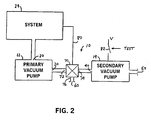
vacuum pumping system 10 in accordance with a second embodiment of the invention is shown in Fig. 2. Like elements in Figs. 1 and 2 have the same reference numerals. In the embodiment of Fig. 2,valve 70 has aninlet 72 connected to exhaust 30 ofprimary vacuum pump 12. Afirst outlet 74 ofvalve 70 is connected toinlet 40 ofsecondary vacuum pump 14, and asecond outlet 76 ofvalve 70 serves asinterpump exhaust 60.Valve 70 maybe a two-way valve that is electronically or pneumatically controlled.Valve 70 may have a first state in whichinlet 72 is connected tofirst outlet 74 and a second state in whichinlet 72 is connected tosecond outlet 76. The state ofvalve 70 is controlled by a control signal on aline 80. In the embodiment of Fig. 2,valve 70 is controlled by a signal representative of pressure insystem 24. Thus, for example,valve 70 may connectinlet 72 tosecond outlet 76 when the pressure insystem 24 is above a selected level and may connectinlet 72 tofirst outlet 74 when the pressure insystem 24 is below the selected level. In other embodiments,valve 70 may be controlled by a different condition, such as for example the pressure atexhaust 30 ofprimary vacuum pump 12. - In the embodiment of Fig. 2
secondary vacuum pump 14 may be enabled when a test, such as a leak test, is being performed and may be disabled when a test is not being performed. By disablingsecondary vacuum pump 14 when a test is not being performed, power consumption can be reduced. As shown, a controllable switch 82 is connected in series with power supply V forsecondary vacuum pump 14. A test signal closes switch 82 when a test is being performed and opens switch 82 when a test is not being performed. It will be understood that that switch 82 may be closed in advance of a test to provide sufficient time for pumping residual light gases fromsystem 24. It will further be understood that different techniques may be utilized for enabling and disablingsecondary vacuum pump 14, within the scope of the invention. - A block diagram of
vacuum pumping system 10 in accordance with a third embodiment of the invention is shown in Fig. 3. Like elements in Figs. 1 and 3 have the same reference numerals. In the embodiment of Fig. 3, the primary vacuum pump is an oil-free scroll vacuum pump 90, and the secondary vacuum pump is an oil-free diaphragm pump 92. In one specific implementation, scroll vacuum pump 90 is a small oil-free scroll pump with a 50 lpm speed and a 500 millitorr base pressure and diaphragm pump 92 is a 5 lpm KNF N84.3. - In addition, Fig. 3 illustrates a packaging technique that may be utilized in accordance with embodiments of the invention. In one embodiment,
system 24, scroll vacuum pump 90 or other primary vacuum pump, diaphragm pump 92 or other secondary vacuum pump andvalve 16 or other valve may be enclosed within asingle package 100, represented schematically in Fig. 3 by dashed lines. Such a packaging configuration is useful for compact and/or portable systems. By way of example,system 24 may be a helium mass spectrometer leak detector. In other embodiments, scroll vacuum pump 90 or other primary vacuum pump, diaphragm pump 92 or other secondary vacuum pump andvalve 16 or other valve may be enclosed within apackage 110, shown schematically in Fig. 3 by dashed lines. - Having thus described various illustrative non-limiting embodiments, and aspects thereof, modifications and alterations will be apparent to those who have skill in the art. Such modifications and alterations are intended to be included in this disclosure, which is for the purpose of illustration and explanation, and not intended to define the limits of the invention. The scope of the invention should be determined from proper construction of the appended claims and equivalents thereof.
Claims (20)
- A vacuum pumping system comprising:a primary vacuum pump having an inlet configured for coupling to a system, and an exhaust, the primary vacuum pump comprising an oil-free, positive displacement vacuum pump having multiple clearance seals between the inlet and the exhaust; anda secondary vacuum pump having an inlet coupled to the exhaust of the primary vacuum pump.
- A vacuum pumping system as defined in claim 1, wherein the primary vacuum pump comprises a scroll vacuum pump.
- A vacuum pumping system as defined in claim 1, wherein the primary vacuum pump comprises a multi-stage roots vacuum pump.
- A vacuum pumping system as defined in claim 1, wherein the primary vacuum pump comprises a multi-stage piston vacuum pump.
- A vacuum pumping system as defined in claim 1, wherein the primary vacuum pump comprises a screw vacuum pump.
- A vacuum pumping system as defined in claim 1, wherein the primary vacuum pump comprises a hook and claw vacuum pump.
- A vacuum pumping system as defined in claim 1, wherein the secondary vacuum pump comprises an oil-free diaphragm vacuum pump.
- A vacuum pumping system as defined in claim 1, wherein the secondary vacuum pump comprises an oil-free scroll vacuum pump.
- A vacuum pumping system as defined in claim 1, further comprising a valve coupled to the exhaust of the primary vacuum pump and configured to provide an interpump exhaust in response to a selected condition.
- A vacuum pumping system as defined in claim 9, wherein the secondary vacuum pump has a lower pumping capacity than the primary vacuum pump.
- A vacuum pumping system as defined in claim 9, wherein the valve comprises a poppet valve configured to open automatically in response to a predetermined pressure differential across the valve.
- A vacuum pumping system as defined in claim 9, wherein the valve comprises a controllable valve configured to couple the exhaust of the primary vacuum pump to the interpump exhaust in response to a sensed pressure level in the system.
- A vacuum pumping system as defined in claim 1, wherein the primary vacuum pump and the secondary vacuum pump are packaged in a single housing.
- A vacuum pumping system as defined in claim 1, wherein the primary vacuum pump and the secondary vacuum pump are configured to provide a high compression ratio for light gases.
- A method for vacuum pumping comprising:pumping a system with a primary vacuum pump having an inlet coupled to the system, and an exhaust, the primary vacuum pump comprising an oil-free, positive displacement vacuum pump having multiple clearance seals between the inlet and the exhaust; andbacking the primary vacuum pump with a secondary vacuum pump having an inlet coupled to the exhaust of the primary vacuum pump.
- A method as defined in claim 15, further comprising coupling the exhaust of the primary vacuum pump to an interpump exhaust in response to a selected condition.
- A method as defined in claim 16, wherein pumping the system with a primary vacuum pump comprises pumping the system with an oil-free scroll vacuum pump and wherein backing the primary vacuum pump with a secondary vacuum pump comprises backing the primary vacuum pump with an oil-free diaphragm pump.
- A vacuum pumping system comprising:a primary vacuum pump having an inlet configured for coupling to a system, and an exhaust, the primary vacuum pump comprising an oil-free scroll vacuum pump;a secondary vacuum pump having an inlet coupled to the exhaust of the primary vacuum pump; anda valve coupled to the exhaust of the primary vacuum pump and configured to couple the exhaust of the primary vacuum pump to an interpump exhaust in response to a selected condition.
- A vacuum pumping system as defined in claim 18, wherein the secondary vacuum pump comprises an oil-free diaphragm pump.
- A vacuum pumping system as defined in claim 19, wherein the valve comprises a poppet valve configured to open automatically in response to a predetermined pressure differential across the valve.
Applications Claiming Priority (2)
| Application Number | Priority Date | Filing Date | Title |
|---|---|---|---|
| US845991 | 2004-05-14 | ||
| US10/845,991 US7189066B2 (en) | 2004-05-14 | 2004-05-14 | Light gas vacuum pumping system |
Publications (2)
| Publication Number | Publication Date |
|---|---|
| EP1596066A1 true EP1596066A1 (en) | 2005-11-16 |
| EP1596066B1 EP1596066B1 (en) | 2011-10-19 |
Family
ID=34936481
Family Applications (1)
| Application Number | Title | Priority Date | Filing Date |
|---|---|---|---|
| EP05010427A Expired - Lifetime EP1596066B1 (en) | 2004-05-14 | 2005-05-13 | Light gas vacuum pumping system |
Country Status (4)
| Country | Link |
|---|---|
| US (1) | US7189066B2 (en) |
| EP (1) | EP1596066B1 (en) |
| JP (1) | JP2005330967A (en) |
| CN (1) | CN100460685C (en) |
Cited By (9)
| Publication number | Priority date | Publication date | Assignee | Title |
|---|---|---|---|---|
| EP1906023A1 (en) * | 2006-09-29 | 2008-04-02 | Anest Iwata Corporation | Evacuation apparatus |
| CN102654117A (en) * | 2011-03-04 | 2012-09-05 | 中国科学院沈阳科学仪器研制中心有限公司 | Air exhausting device for vacuum pump |
| EP1979619A4 (en) * | 2006-01-31 | 2013-07-24 | Ebara Corp | VACUUM PUMP UNIT |
| DE102010009083B4 (en) * | 2009-03-24 | 2013-09-26 | Vacuubrand Gmbh + Co Kg | vacuum pump |
| WO2014095432A1 (en) * | 2012-12-22 | 2014-06-26 | Oerlikon Leybold Vacuum Gmbh | Pumping unit for pumping light gases, and use of the pumping unit |
| CN105865724A (en) * | 2016-04-18 | 2016-08-17 | 浙江优机机械科技有限公司 | Tense-lax and increasing-sluicing synchronous intelligent valve test bed and detection method |
| GB2543599A (en) * | 2015-06-05 | 2017-04-26 | Agilent Technologies Inc | Vacuum pump system with light gas pumping and leak detection apparatus comprising the same |
| US9982666B2 (en) | 2015-05-29 | 2018-05-29 | Agilient Technologies, Inc. | Vacuum pump system including scroll pump and secondary pumping mechanism |
| WO2018130819A1 (en) * | 2017-01-11 | 2018-07-19 | Edwards Limited | A multiple stage vacuum pump and pump configuring method |
Families Citing this family (15)
| Publication number | Priority date | Publication date | Assignee | Title |
|---|---|---|---|---|
| EP2458218A1 (en) | 2010-11-30 | 2012-05-30 | Converteam Technology Ltd | A system for maintaining a high vacuum |
| CA2836502C (en) * | 2011-05-20 | 2019-07-02 | Bp Exploration Operating Company Limited | Pump |
| US8806919B2 (en) * | 2011-07-29 | 2014-08-19 | Vacuum Technology Inc. | Leak detection apparatus and method |
| DE102013218506A1 (en) * | 2013-09-16 | 2015-03-19 | Inficon Gmbh | Sniffer leak detector with multi-stage diaphragm pump |
| DE102013219464A1 (en) * | 2013-09-26 | 2015-03-26 | Inficon Gmbh | Evacuation of a foil chamber |
| CN104632629A (en) * | 2013-11-13 | 2015-05-20 | 中国科学院沈阳科学仪器股份有限公司 | Vacuum system for efficiently pumping gases with small molecular weights |
| WO2015182699A1 (en) * | 2014-05-30 | 2015-12-03 | 株式会社 荏原製作所 | Gas-evacuation system |
| CN104791223A (en) * | 2015-03-23 | 2015-07-22 | 苏州固基电子科技有限公司 | Air valve with pipe leakage detection function |
| DE102015215982B4 (en) * | 2015-08-21 | 2017-03-16 | Magna Powertrain Bad Homburg GmbH | Pump and system for supplying a consumer |
| TWI630359B (en) * | 2016-04-13 | 2018-07-21 | 復盛股份有限公司 | Compressor apparatus |
| CN106762641A (en) * | 2016-11-28 | 2017-05-31 | 陈琼 | A kind of vacuum combined unit |
| CN108533494B (en) * | 2018-06-19 | 2024-02-20 | 浙江维朋制冷设备有限公司 | Vacuum pump |
| US11872424B2 (en) * | 2019-10-04 | 2024-01-16 | Hamilton Sundstrand Corporation | Process water gas management of electrolyzer system with membrane |
| GB2631511B (en) * | 2023-07-05 | 2026-04-01 | Edwards Ltd | Pumping system |
| WO2025008606A1 (en) * | 2023-07-05 | 2025-01-09 | Edwards Limited | Claw booster pump |
Citations (6)
| Publication number | Priority date | Publication date | Assignee | Title |
|---|---|---|---|---|
| EP0730093A1 (en) * | 1995-02-28 | 1996-09-04 | Iwata Air Compressor Mfg. Co.,Ltd. | Control of a two-stage vacuum pump |
| US5709537A (en) * | 1992-09-03 | 1998-01-20 | Matsushita Electric Industrial Co., Ltd. | Evacuating apparatus |
| US5855473A (en) * | 1995-06-07 | 1999-01-05 | Varian Associates, Inc. | High displacement rate,scroll-type, fluid handling apparatus |
| EP1101942A2 (en) * | 1999-11-17 | 2001-05-23 | Teijin Seiki Co., Ltd. | Evacuating apparatus |
| US20020131870A1 (en) * | 2001-03-19 | 2002-09-19 | Alcatel | System for pumping low thermal conductivity gases |
| WO2003023229A1 (en) * | 2001-09-06 | 2003-03-20 | Ulvac, Inc. | Vacuum pumping system and method of operating vacuum pumping system |
Family Cites Families (7)
| Publication number | Priority date | Publication date | Assignee | Title |
|---|---|---|---|---|
| US4499752A (en) | 1983-06-22 | 1985-02-19 | Varian Associates, Inc. | Counterflow leak detector with cold trap |
| US4735084A (en) | 1985-10-01 | 1988-04-05 | Varian Associates, Inc. | Method and apparatus for gross leak detection |
| DE4140366A1 (en) * | 1991-12-07 | 1993-06-09 | Leybold Ag, 6450 Hanau, De | LEAK DETECTOR FOR VACUUM SYSTEMS AND METHOD FOR CARRYING OUT THE LEAK DETECTOR ON VACUUM SYSTEMS |
| DE4408877A1 (en) * | 1994-03-16 | 1995-09-21 | Leybold Ag | Test gas leak detector |
| DE9405028U1 (en) * | 1994-03-24 | 1994-06-09 | Leybold AG, 50968 Köln | Test gas leak detector |
| US5542828A (en) | 1994-11-17 | 1996-08-06 | Grenci; Charles A. | Light-gas-isolation, oil-free, scroll vaccum-pump system |
| DE19638506A1 (en) * | 1996-09-20 | 1998-03-26 | Leybold Vakuum Gmbh | Procedure for examining a plurality of similar test objects for leaks and leak detectors suitable for carrying out this procedure |
-
2004
- 2004-05-14 US US10/845,991 patent/US7189066B2/en not_active Expired - Lifetime
-
2005
- 2005-05-11 CN CNB2005100817225A patent/CN100460685C/en not_active Expired - Fee Related
- 2005-05-13 EP EP05010427A patent/EP1596066B1/en not_active Expired - Lifetime
- 2005-05-13 JP JP2005141438A patent/JP2005330967A/en active Pending
Patent Citations (6)
| Publication number | Priority date | Publication date | Assignee | Title |
|---|---|---|---|---|
| US5709537A (en) * | 1992-09-03 | 1998-01-20 | Matsushita Electric Industrial Co., Ltd. | Evacuating apparatus |
| EP0730093A1 (en) * | 1995-02-28 | 1996-09-04 | Iwata Air Compressor Mfg. Co.,Ltd. | Control of a two-stage vacuum pump |
| US5855473A (en) * | 1995-06-07 | 1999-01-05 | Varian Associates, Inc. | High displacement rate,scroll-type, fluid handling apparatus |
| EP1101942A2 (en) * | 1999-11-17 | 2001-05-23 | Teijin Seiki Co., Ltd. | Evacuating apparatus |
| US20020131870A1 (en) * | 2001-03-19 | 2002-09-19 | Alcatel | System for pumping low thermal conductivity gases |
| WO2003023229A1 (en) * | 2001-09-06 | 2003-03-20 | Ulvac, Inc. | Vacuum pumping system and method of operating vacuum pumping system |
Cited By (11)
| Publication number | Priority date | Publication date | Assignee | Title |
|---|---|---|---|---|
| EP1979619A4 (en) * | 2006-01-31 | 2013-07-24 | Ebara Corp | VACUUM PUMP UNIT |
| EP1906023A1 (en) * | 2006-09-29 | 2008-04-02 | Anest Iwata Corporation | Evacuation apparatus |
| DE102010009083B4 (en) * | 2009-03-24 | 2013-09-26 | Vacuubrand Gmbh + Co Kg | vacuum pump |
| CN102654117A (en) * | 2011-03-04 | 2012-09-05 | 中国科学院沈阳科学仪器研制中心有限公司 | Air exhausting device for vacuum pump |
| WO2014095432A1 (en) * | 2012-12-22 | 2014-06-26 | Oerlikon Leybold Vacuum Gmbh | Pumping unit for pumping light gases, and use of the pumping unit |
| US9982666B2 (en) | 2015-05-29 | 2018-05-29 | Agilient Technologies, Inc. | Vacuum pump system including scroll pump and secondary pumping mechanism |
| GB2543599A (en) * | 2015-06-05 | 2017-04-26 | Agilent Technologies Inc | Vacuum pump system with light gas pumping and leak detection apparatus comprising the same |
| US10094381B2 (en) | 2015-06-05 | 2018-10-09 | Agilent Technologies, Inc. | Vacuum pump system with light gas pumping and leak detection apparatus comprising the same |
| GB2543599B (en) * | 2015-06-05 | 2020-12-09 | Agilent Technologies Inc | Vacuum pump system with light gas pumping and leak detection apparatus comprising the same |
| CN105865724A (en) * | 2016-04-18 | 2016-08-17 | 浙江优机机械科技有限公司 | Tense-lax and increasing-sluicing synchronous intelligent valve test bed and detection method |
| WO2018130819A1 (en) * | 2017-01-11 | 2018-07-19 | Edwards Limited | A multiple stage vacuum pump and pump configuring method |
Also Published As
| Publication number | Publication date |
|---|---|
| HK1084562A1 (en) | 2006-07-21 |
| EP1596066B1 (en) | 2011-10-19 |
| CN1707102A (en) | 2005-12-14 |
| JP2005330967A (en) | 2005-12-02 |
| US7189066B2 (en) | 2007-03-13 |
| US20050254981A1 (en) | 2005-11-17 |
| CN100460685C (en) | 2009-02-11 |
Similar Documents
| Publication | Publication Date | Title |
|---|---|---|
| US7189066B2 (en) | Light gas vacuum pumping system | |
| US10094381B2 (en) | Vacuum pump system with light gas pumping and leak detection apparatus comprising the same | |
| US9316559B2 (en) | Leak detection appliance | |
| JP3568536B2 (en) | Leak detector having a vacuum pump and method of operating the leak detector | |
| CN100533091C (en) | leak monitor | |
| CS211374B2 (en) | Liquid circling pump with prearranged compressor | |
| US5703281A (en) | Ultra high vacuum pumping system and high sensitivity helium leak detector | |
| US11428598B2 (en) | Leak detector for checking sealing tightness of an object comprising a pumping device including a turbomolecular pump and first and second vacuum pumps having at least one first and second pumping stage wherein the outlet of the second vacuum pump is connected between pumping stages of the first vacuum pump | |
| US5542828A (en) | Light-gas-isolation, oil-free, scroll vaccum-pump system | |
| US7082813B2 (en) | Test gas leakage detector | |
| TW201802444A (en) | Mass-spectrometric leak detector with turbomolecular pump and booster pump on a common shaft | |
| US5974864A (en) | Leak detector with back-up pump | |
| US20250020534A1 (en) | Vacuum leak detector with multistage vacuum pump and integrated gas-specific gas sensor and method for producing a vacuum leak detector | |
| CN101473208B (en) | System and method for detecting trace gas leaks at large leaks under relatively high test pressure | |
| US7670119B2 (en) | Multistage vacuum pump and a pumping installation including such a pump | |
| HK1084562B (en) | Leak detector system and method for vacuum pumping leak detector | |
| JPH0315678A (en) | Vacuum pump system | |
| Hablanian | Prevention of overload in high‐vacuum systems | |
| Thomas et al. | A study of the feasibility of mechanical pumps for use with the Pioneer-Venus probe mass spectrometer inlet system | |
| HK1132036B (en) | System and method for trace gas leak detection of large leaks at relatively high test pressures |
Legal Events
| Date | Code | Title | Description |
|---|---|---|---|
| PUAI | Public reference made under article 153(3) epc to a published international application that has entered the european phase |
Free format text: ORIGINAL CODE: 0009012 |
|
| AK | Designated contracting states |
Kind code of ref document: A1 Designated state(s): AT BE BG CH CY CZ DE DK EE ES FI FR GB GR HU IE IS IT LI LT LU MC NL PL PT RO SE SI SK TR |
|
| AX | Request for extension of the european patent |
Extension state: AL BA HR LV MK YU |
|
| 17P | Request for examination filed |
Effective date: 20060324 |
|
| AKX | Designation fees paid |
Designated state(s): DE FR GB |
|
| 17Q | First examination report despatched |
Effective date: 20070108 |
|
| RAP1 | Party data changed (applicant data changed or rights of an application transferred) |
Owner name: AGILENT TECHNOLOGIES, INC. |
|
| GRAP | Despatch of communication of intention to grant a patent |
Free format text: ORIGINAL CODE: EPIDOSNIGR1 |
|
| GRAS | Grant fee paid |
Free format text: ORIGINAL CODE: EPIDOSNIGR3 |
|
| GRAA | (expected) grant |
Free format text: ORIGINAL CODE: 0009210 |
|
| AK | Designated contracting states |
Kind code of ref document: B1 Designated state(s): DE FR GB |
|
| REG | Reference to a national code |
Ref country code: GB Ref legal event code: FG4D |
|
| REG | Reference to a national code |
Ref country code: DE Ref legal event code: R096 Ref document number: 602005030657 Country of ref document: DE Effective date: 20111215 |
|
| PLBE | No opposition filed within time limit |
Free format text: ORIGINAL CODE: 0009261 |
|
| STAA | Information on the status of an ep patent application or granted ep patent |
Free format text: STATUS: NO OPPOSITION FILED WITHIN TIME LIMIT |
|
| 26N | No opposition filed |
Effective date: 20120720 |
|
| REG | Reference to a national code |
Ref country code: DE Ref legal event code: R097 Ref document number: 602005030657 Country of ref document: DE Effective date: 20120720 |
|
| GBPC | Gb: european patent ceased through non-payment of renewal fee |
Effective date: 20120513 |
|
| PG25 | Lapsed in a contracting state [announced via postgrant information from national office to epo] |
Ref country code: GB Free format text: LAPSE BECAUSE OF NON-PAYMENT OF DUE FEES Effective date: 20120513 |
|
| REG | Reference to a national code |
Ref country code: FR Ref legal event code: PLFP Year of fee payment: 11 |
|
| PGFP | Annual fee paid to national office [announced via postgrant information from national office to epo] |
Ref country code: FR Payment date: 20150508 Year of fee payment: 11 |
|
| REG | Reference to a national code |
Ref country code: FR Ref legal event code: ST Effective date: 20170131 |
|
| PG25 | Lapsed in a contracting state [announced via postgrant information from national office to epo] |
Ref country code: FR Free format text: LAPSE BECAUSE OF NON-PAYMENT OF DUE FEES Effective date: 20160531 |
|
| PGFP | Annual fee paid to national office [announced via postgrant information from national office to epo] |
Ref country code: DE Payment date: 20200428 Year of fee payment: 16 |
|
| REG | Reference to a national code |
Ref country code: DE Ref legal event code: R082 Ref document number: 602005030657 Country of ref document: DE Representative=s name: KILBURN & STRODE LLP, NL |
|
| REG | Reference to a national code |
Ref country code: DE Ref legal event code: R119 Ref document number: 602005030657 Country of ref document: DE |
|
| PG25 | Lapsed in a contracting state [announced via postgrant information from national office to epo] |
Ref country code: DE Free format text: LAPSE BECAUSE OF NON-PAYMENT OF DUE FEES Effective date: 20211201 |