EP1596058A1 - Connector arrangement - Google Patents
Connector arrangement Download PDFInfo
- Publication number
- EP1596058A1 EP1596058A1 EP04252808A EP04252808A EP1596058A1 EP 1596058 A1 EP1596058 A1 EP 1596058A1 EP 04252808 A EP04252808 A EP 04252808A EP 04252808 A EP04252808 A EP 04252808A EP 1596058 A1 EP1596058 A1 EP 1596058A1
- Authority
- EP
- European Patent Office
- Prior art keywords
- positive
- stack
- terminal
- connector arrangement
- negative
- Prior art date
- Legal status (The legal status is an assumption and is not a legal conclusion. Google has not performed a legal analysis and makes no representation as to the accuracy of the status listed.)
- Granted
Links
- 238000009826 distribution Methods 0.000 claims abstract description 54
- 239000000446 fuel Substances 0.000 claims description 30
- 239000012212 insulator Substances 0.000 claims description 26
- 238000000034 method Methods 0.000 claims description 19
- 239000000853 adhesive Substances 0.000 claims description 10
- 230000001070 adhesive effect Effects 0.000 claims description 10
- 239000004020 conductor Substances 0.000 claims description 8
- 238000005538 encapsulation Methods 0.000 claims description 7
- 230000007704 transition Effects 0.000 claims description 7
- 239000004593 Epoxy Substances 0.000 claims description 5
- 238000003754 machining Methods 0.000 claims description 4
- 239000002654 heat shrinkable material Substances 0.000 claims description 3
- 239000000463 material Substances 0.000 description 12
- 238000002485 combustion reaction Methods 0.000 description 5
- 238000007789 sealing Methods 0.000 description 5
- 230000002706 hydrostatic effect Effects 0.000 description 4
- 230000008901 benefit Effects 0.000 description 3
- 239000000919 ceramic Substances 0.000 description 3
- 230000000694 effects Effects 0.000 description 3
- PXHVJJICTQNCMI-UHFFFAOYSA-N Nickel Chemical compound [Ni] PXHVJJICTQNCMI-UHFFFAOYSA-N 0.000 description 2
- 229910010293 ceramic material Inorganic materials 0.000 description 2
- 229920002313 fluoropolymer Polymers 0.000 description 2
- 239000004811 fluoropolymer Substances 0.000 description 2
- 238000002347 injection Methods 0.000 description 2
- 239000007924 injection Substances 0.000 description 2
- 229920000642 polymer Polymers 0.000 description 2
- 239000007787 solid Substances 0.000 description 2
- 229910000906 Bronze Inorganic materials 0.000 description 1
- OAICVXFJPJFONN-UHFFFAOYSA-N Phosphorus Chemical compound [P] OAICVXFJPJFONN-UHFFFAOYSA-N 0.000 description 1
- 238000004026 adhesive bonding Methods 0.000 description 1
- 230000002411 adverse Effects 0.000 description 1
- 239000010974 bronze Substances 0.000 description 1
- 230000006835 compression Effects 0.000 description 1
- 238000007906 compression Methods 0.000 description 1
- 230000001595 contractor effect Effects 0.000 description 1
- KUNSUQLRTQLHQQ-UHFFFAOYSA-N copper tin Chemical compound [Cu].[Sn] KUNSUQLRTQLHQQ-UHFFFAOYSA-N 0.000 description 1
- 238000006073 displacement reaction Methods 0.000 description 1
- 238000001125 extrusion Methods 0.000 description 1
- 239000012530 fluid Substances 0.000 description 1
- PCHJSUWPFVWCPO-UHFFFAOYSA-N gold Chemical compound [Au] PCHJSUWPFVWCPO-UHFFFAOYSA-N 0.000 description 1
- 229910052737 gold Inorganic materials 0.000 description 1
- 239000010931 gold Substances 0.000 description 1
- 239000011810 insulating material Substances 0.000 description 1
- 238000009413 insulation Methods 0.000 description 1
- 238000004519 manufacturing process Methods 0.000 description 1
- 239000002184 metal Substances 0.000 description 1
- 229910052751 metal Inorganic materials 0.000 description 1
- 229910052759 nickel Inorganic materials 0.000 description 1
- 231100000989 no adverse effect Toxicity 0.000 description 1
- 239000003566 sealing material Substances 0.000 description 1
- 229910000679 solder Inorganic materials 0.000 description 1
Images


Classifications
-
- F—MECHANICAL ENGINEERING; LIGHTING; HEATING; WEAPONS; BLASTING
- F02—COMBUSTION ENGINES; HOT-GAS OR COMBUSTION-PRODUCT ENGINE PLANTS
- F02M—SUPPLYING COMBUSTION ENGINES IN GENERAL WITH COMBUSTIBLE MIXTURES OR CONSTITUENTS THEREOF
- F02M51/00—Fuel-injection apparatus characterised by being operated electrically
- F02M51/005—Arrangement of electrical wires and connections, e.g. wire harness, sockets, plugs; Arrangement of electronic control circuits in or on fuel injection apparatus
-
- H—ELECTRICITY
- H10—SEMICONDUCTOR DEVICES; ELECTRIC SOLID-STATE DEVICES NOT OTHERWISE PROVIDED FOR
- H10N—ELECTRIC SOLID-STATE DEVICES NOT OTHERWISE PROVIDED FOR
- H10N30/00—Piezoelectric or electrostrictive devices
- H10N30/80—Constructional details
- H10N30/87—Electrodes or interconnections, e.g. leads or terminals
- H10N30/875—Further connection or lead arrangements, e.g. flexible wiring boards, terminal pins
Definitions
- the piezoelectric stack is often located within a fuel-filled accumulator volume or chamber so that the compressive load applied to the piezoelectric stack is provided by hydrostatic pressure.
- An actuator of this type is described in our co-pending, published European patent application, EP 0995901 A.
- Fuel in the accumulator chamber is at high pressure, typically around 2000 bar, and so hydrostatic loading of the stack is high.
- the stack is encapsulated within a polymer casing or sleeve which serves to prevent the ingress of fuel into the stack structure.
- This aspect of the invention provides a convenient method of forming the distribution electrodes of the connector arrangement, after the terminals and the stack have been assembled together. Hence, there is no need for fragile distribution electrodes to be contacted with connector terminals at the same time as the connector arrangement and the stack are assembled together. Instead, the distribution electrodes are formed only after the stack and terminals have been brought into contact and fixed (i.e. glued) together.
- An electrical connector 28, or connector module, is arranged at the upper end of the accumulator volume 22 to provide an electrical voltage to the positive and negative distribution electrodes.
- the connector module 28 includes positive and negative terminals which connect with a respective one of the distribution electrodes to allow an external voltage to be applied to the internal stack electrodes. In the scale of the drawing shown in Figure 1, the individual terminals of the connector cannot be identified. By controlling the voltage across the stack 26, the length of the stack 26 can be extended and contracted, thereby causing the control piston 12 to be moved to control pressure in the chamber 14.
- Figure 3(b) shows the insulator layer 40 which locates between the stems 30b, 32b of the positive and negative terminals 30, 32.
- the insulator layer 40 may take the form of a T-shaped washer having a stem or body 40a and a cross-piece 40b.
- the material from which the insulator layer 40 is formed is selected as one having a mechanical modulus of elasticity which is close to that of the material used for the terminals 30, 32. Using a material with this property ensures a substantially homogeneous stress footprint is achieved on the piezoelectric stack 26. This is important as the piezoelectric material from which the stack 26 is formed, being a ceramic, is highly brittle.
- the insulator layer 40 may be formed from paper, such as aramid-type insulating paper.
- the insulator layer 40 may be formed from a ceramic material, although this will result in an increased layer thickness between the terminals 30, 32.
- the distribution electrodes 44a, 44b may be soldered or otherwise bonded to the stack 26. Once the terminals 30, 32 are brought into contact with the distribution electrodes 44a, 44b, a solder is applied to secure the electrical connection.
- the encapsulated actuator arrangement 10 When in use, the encapsulated actuator arrangement 10 is located within the fuel-filled accumulator volume 22 of the injector. The upper ends of the terminal blades 30a, 32b are brought into contact with the external supply voltage, via a harness connector, to allow voltage control of the stack 26. Due to the outer encapsulation sleeve and the annular seal 36, the stack elements and regions of electrical contact are protected from high pressure fuel within the volume 22.
Landscapes
- Engineering & Computer Science (AREA)
- Chemical & Material Sciences (AREA)
- Combustion & Propulsion (AREA)
- Mechanical Engineering (AREA)
- General Engineering & Computer Science (AREA)
- Fuel-Injection Apparatus (AREA)
- Piezo-Electric Or Mechanical Vibrators, Or Delay Or Filter Circuits (AREA)
- Coupling Device And Connection With Printed Circuit (AREA)
- Mechanical Coupling Of Light Guides (AREA)
- General Electrical Machinery Utilizing Piezoelectricity, Electrostriction Or Magnetostriction (AREA)
Abstract
Description
- The present invention relates to an electrical connector arrangement for a piezoelectric actuator and, in particular, to an electrical connector arrangement for a piezoelectric actuator of the type suitable for use in a fuel injector for an internal combustion engine. The invention also relates to an actuator incorporating an electrical connector arrangement and methods of forming an electrical connector arrangement.
- Fuel injectors for delivering predetermined quantities of fuel into a combustion space of an internal combustion engine, or the like, generally comprise a piston which is actuable to control the pressure of fuel contained within an injector control chamber. The control chamber is defined, in part, by a surface associated with a valve needle such that changes in fuel pressure within the control chamber effect movement of the valve needle, thereby causing fuel to be delivered into the combustion space of the engine.
- It is known to provide such fuel injectors with a piezoelectric actuator for controlling movement of the control piston. Such actuators generally consist of a piezoelectric body in the form of a multi-layer laminate or "stack" having layers of piezoelectric or piezoceramic material separated by metal or electrically conductive layers which act as internal electrodes. Positive and negative distribution electrodes are provided on the stack to make contact with the internal electrodes. The distribution electrodes are connected to an external voltage supply, thereby to allow a voltage to be applied across the stack.
- The piezoelectric actuator is arranged to convert electrical energy into mechanical or kinetic energy such that the application of an external voltage to the internal electrodes causes the piezoelectric material to expand or contract in dependence upon the magnitude and polarity of the voltage applied. The change in length of the stack which results from this expansion or contraction effects movement of the control piston and, hence, opening and closing of the valve needle.
- It is known that the amount of compressive load applied to the piezoelectric stack can significantly influence actuator performance and durability. More specifically, the piezoelectric or piezoceramic material from which the stack is formed is capable of withstanding compressive stress but cannot withstand significant tensile stress. It is therefore advantageous to ensure that a compressive load on the stack is maintained throughout the operating cycle of the injector.
- In known piezoelectrically operable fuel injectors used in diesel engines, the piezoelectric stack is often located within a fuel-filled accumulator volume or chamber so that the compressive load applied to the piezoelectric stack is provided by hydrostatic pressure. An actuator of this type is described in our co-pending, published European patent application, EP 0995901 A. Fuel in the accumulator chamber is at high pressure, typically around 2000 bar, and so hydrostatic loading of the stack is high. The stack is encapsulated within a polymer casing or sleeve which serves to prevent the ingress of fuel into the stack structure.
- With the stack located within such a high pressure environment, it is a challenge not only to ensure that the electrical connections to the stack are adequately sealed from high pressure fuel within the accumulator volume but also that any associated insulation or sealing of the stack is not affected detrimentally by the high hydrostatic forces.
- It is an object of the present invention to provide an electrical connector arrangement for a piezoelectric actuator which addresses the aforementioned concerns.
- According to a first aspect of the invention, there is provided an electrical connector arrangement for a piezoelectric actuator having a stack of one or more piezoelectric elements, the electrical connector arrangement comprising positive and negative terminals for connection with a distribution electrode means of the piezoelectric stack, wherein each of the positive and negative terminals has a terminal end face which locates adjacent to an end face of the stack, in use, and a radially outer face for contact with the distribution electrode means.
- The connector arrangement is particularly suitable for use in a piezoelectric actuator of the type used in a fuel injector, where the actuator is located within an accumulator volume or chamber filled with high pressure fluid (e.g. fuel). The distribution electrodes means connects with an external voltage supply, in use, so as to enable a voltage to be applied across the stack to effect changes in stack length.
- In a preferred embodiment, the terminal end face of each of the positive and negative terminals is defined by a base section of the terminal. Each base section defines a respective positive or negative radially outer face for contact with the distribution electrode means. It is a preferred feature that the base section of each of the positive and negative terminals takes the form of a block. Typically, the terminal blocks are arranged so that they locate immediately next to the stack end face. It is convenient to attach the terminal end faces to the stack end face by gluing.
- The distribution electrode means includes a positive distribution electrode for connection with the positive terminal and a negative distribution electrode for connection with the negative terminal.
- By making the contact with the distribution electrodes means through a solid, terminal block, rigidity of the connector arrangement is improved. Furthermore, extrusion paths for any sealing material which may be used can be minimised or removed altogether. It is a further advantage that the overall 'envelope' of the terminal assembly is similar to that of the stack, removing geometric transitions between the terminals and the stack and making encapsulation of the stack much easier.
- In a further preferred embodiment, each of the positive and negative terminals includes a terminal stem which extends from its block to terminate in a terminal blade for connection with the external voltage supply, in use.
- The terminals, and in particular those regions comprised of the blocks and the stems of the terminals, are preferably spaced apart by an insulator layer, for example an aramid-type paper washer.
- It is preferable for the insulator layer to be joined to the positive and negative terminals, one on either side thereof, by means of an adhesive.
- In a particularly preferred embodiment, the connector arrangement further comprises an insulating sleeve within which at least a portion of each terminal stem is received. Typically, the insulating sleeve is formed from a heat-shrinkable material. The provision of the sleeve serves to prevent electrical arcing between the terminals and also prevents arcing to the surrounding parts of the assembly (e.g. the body of the injector housing).
- In one preferred embodiment, the connector arrangement includes an annular seal which surrounds the insulating sleeve for the terminals. Preferably, the stem and the block of each of the positive and negative terminals define a step therebetween which forms an abutment surface against which the annular seal seats.
- Preferably, the annular seal is axi-symmetric in shape and is formed from a ceramic material. It is further preferable for the annular seal to be joined to the abutment surface by means of an adhesive. When employed in a piezoelectrically operable injector of the aforementioned type, the annular seal locates around the insulating sleeve to provide a seal between the accumulator volume and that part of the connector arrangement (i.e. the terminal blades) which connect with the external voltage supply, in use.
- In a further preferred embodiment, the annular seal is provided with one or more annular grooves on its outer circumferential surface. The provision of the grooves serves to enhance the seal between the annular seal and any surrounding encapsulation sleeve which is provided on the actuator.
- According to a second aspect of the invention, there is provided a piezoelectric actuator for use in a fuel injector, the actuator including a stack of one or more piezoelectric elements, wherein the stack is provided with a positive distribution electrode and a negative distribution electrode across which a voltage is applied, and an electrical connector arrangement in accordance with the first aspect of the invention, wherein the distribution electrodes extend beyond the stack end face so that a radially outer contact face of each of the positive and negative terminals of the connector arrangement contacts an inner contact face of a corresponding one of the positive and negative distribution electrodes.
- Preferred and/or optional features of the first aspect of the invention may be incorporated within the actuator of the second aspect of the invention also.
- The piezoelectric stack may consist of a plurality of layers of piezoelectric or piezoceramic material, interspersed with a plurality of layers of electrically conductive material which connect with the distribution electrodes. In a preferred embodiment, the layers of piezoelectric or piezoceramic material are each separated by a layer of electrically conductive material which forms a positive and negative electrode pair. The distribution electrodes are preferably provided on outer surfaces of the stack.
- According to a third aspect of the present invention, there is provided a method of forming an electrical connector arrangement of the first aspect of the invention, the method including the steps of providing a block of electrically conductive material, machining the block to define the positive and negative terminals, each of the terminals having at least a terminal blade and a terminal base, bisecting the block axially so as to separate the positive and negative terminals, and sandwiching an insulator layer between the positive and negative terminals to isolate said terminals from one another electrically.
- Preferably, each terminal includes a terminal stem located between the terminal base and the terminal blade.
- According to a fourth aspect of the invention, a method of forming an electrical connector arrangement of the first aspect of the invention includes the steps of providing a block of electrically conductive material having a layer of insulator therein, and subsequently machining the block to define the positive and negative terminals which are separated by the insulator layer.
- According to a fifth aspect of the invention, a method of forming an electrical connector arrangement of the first aspect of the invention includes (i) affixing the terminal end faces to the stack end face, and (ii) subsequently providing positive and negative distribution electrodes to respective outer faces of the stack so that the positive electrode spans the transition between the stack and the positive terminal and the negative electrode spans the transition between the stack and the negative terminal.
- The method may, in one embodiment, include the step of providing a first layer of conductive epoxy to span the positive terminal and a first side of the stack so as to define the positive distribution electrode and providing a second layer of conductive epoxy to span the negative terminal and a second side of the stack so as to define the negative distribution electrode.
- This aspect of the invention provides a convenient method of forming the distribution electrodes of the connector arrangement, after the terminals and the stack have been assembled together. Hence, there is no need for fragile distribution electrodes to be contacted with connector terminals at the same time as the connector arrangement and the stack are assembled together. Instead, the distribution electrodes are formed only after the stack and terminals have been brought into contact and fixed (i.e. glued) together.
- For the purpose of this specification, references to 'upper' and 'lower' are used for convenience when referring to the orientation of the drawings, but shall not be taken as limiting.
- The present invention will now be described, by way of example only, with reference to the accompanying drawings in which:
- Figure 1 is a schematic view of a fuel injector of the type having a piezoelectric actuator with which the electrical connector arrangement of the present invention may be used,
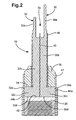
- Figure 2 is a section view of an electrical connector arrangement of the present invention,
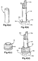
- Figures 3(a) to (c) show individual parts of the electrical connector arrangement in Figure 2, prior to assembly thereof, and Figure 3(d) shows a terminal module of the connector arrangement when fully assembled,
- Figures 4(a) to (d) illustrate the further assembly stages of the electrical connector arrangement, once the terminal module of Figure 3(d) has been assembled,
- Figure 5 is a view of the fully assembled electrical connector arrangement (i.e. similar to that shown in Figure 2) in connection with the piezoelectric actuator, and
- Figure 6 is a perspective view of a 'connector block' which may be used in the manufacture of the electrical connector arrangement in Figures 2 to 5.
-
- Referring to Figure 1, a piezoelectrically actuated fuel injector for a compression ignition internal combustion engine (diesel engine) includes a piezoelectric actuator, referred to generally as 10, which is arranged to control movement of an
injector piston 12. In turn, the piston controls fuel pressure within acontrol chamber 14 which is arranged at the back of aninjector valve needle 16. By controlling fuel pressure within thecontrol chamber 14, aninjector valve needle 16 is moved towards and away from a valve needle seating so as to control whether or not injection occurs through one ormore injector outlets 18. - High pressure fuel for injection is delivered to an
injector inlet 20 located at the upper end of the injector remote from theoutlets 18. Theinlet 20 supplies fuel, via anaccumulator volume 22, to adownstream injector passage 24 and, hence, to theinjector outlets 18. Theaccumulator volume 22 is thus flooded with high pressure fuel, and it is within this volume that astack 26 of thepiezoelectric actuator 10 is located. - The
stack 26 comprises a plurality of piezoelectric elements which are separated by internal electrodes (not shown) in a known manner. External electrode means, in the form of positive and negative distribution electrodes (also not shown), are provided on thestack 26 to make appropriate contact with the internal stack electrodes. - An
electrical connector 28, or connector module, is arranged at the upper end of theaccumulator volume 22 to provide an electrical voltage to the positive and negative distribution electrodes. Theconnector module 28 includes positive and negative terminals which connect with a respective one of the distribution electrodes to allow an external voltage to be applied to the internal stack electrodes. In the scale of the drawing shown in Figure 1, the individual terminals of the connector cannot be identified. By controlling the voltage across thestack 26, the length of thestack 26 can be extended and contracted, thereby causing thecontrol piston 12 to be moved to control pressure in thechamber 14. - In order to protect the
piezoelectric stack 26 from the surrounding high pressure fuel within thevolume 22, thestack 26, including the distribution electrodes, is encapsulated within a polymer casing or sleeve in a known manner. As thepiezoelectric stack 26 is located within the fuel-filledvolume 22, it is important that theconnector module 28 is not only sealed from fuel within the volume but also that theconnector module 28, and any necessary sealing parts therefor, can withstand the large hydrostatic forces within thevolume 22 with no adverse effect. - The
connector module 28 is shown in more detail in Figure 2, where it can be seen that themodule 28 includes a first,positive terminal 30 and a second,negative terminal 32. Each of the positive andnegative terminals terminal blade body base terminal blades vacant volume 38 therebetween, whereas thestem base insulator member 40. The insulator member takes the form of alayer 40 of insulating material and is sandwiched between the positive and negative terminal stems and base sections, 30b, 32b and 30c, 32c respectively. - The
base terminal assembly stack 26. The upper face of eachterminal block stem abutment surface 34. - Positive and
negative distribution electrodes stack 26, each of which makes contact with a radiallyouter contact face outer contact face negative distribution electrodes electrode - The stems 30b, 32b of the
terminals tube 46. Typically, thesleeve 46 is formed from a heat-shrinkable material. An annularceramic seal 36 locates over thesleeve 46 to seat against theabutment surface 34 in a sealing manner. - Once the
connector module 28 and thepiezoelectric stack 26 have been brought into electrical contact in the aforementioned manner, thestack 26 is then encapsulated within an outer sleeve or shield 47 which, when assembled within the injector, protects the elements of thestack 26 from surrounding high pressure fuel within theaccumulator volume 22. The manner in which the assembledactuator 10 andconnector module 28 may be encapsulated within theouter shield 47 is described in our co-pending International patent application WO 02/061856. - Figures 3 illustrates more clearly the separate components of the electrical connector and the method by which the
connector module 28 may be assembled. Figure 3(a) shows thenegative terminal 32 and Figure 3(c) shows thepositive terminal 30. Bothterminals - Both the
stem block terminal blades - Figure 3(b) shows the
insulator layer 40 which locates between thestems negative terminals insulator layer 40 may take the form of a T-shaped washer having a stem orbody 40a and across-piece 40b. The material from which theinsulator layer 40 is formed is selected as one having a mechanical modulus of elasticity which is close to that of the material used for theterminals piezoelectric stack 26. This is important as the piezoelectric material from which thestack 26 is formed, being a ceramic, is highly brittle. - Typically, for example, the
insulator layer 40 may be formed from paper, such as aramid-type insulating paper. Alternatively, theinsulator layer 40 may be formed from a ceramic material, although this will result in an increased layer thickness between theterminals - The profile of the body or stem 40a of the
insulator layer 40 is shaped appropriately to match that of the terminal stems 30b, 32b. The cross-piece 40b of theinsulator layer 40 is shaped to match that of the terminal blocks 30c, 32c. An inwardly facing (inner)flat surface terminal stem insulator layer 40 therebetween. Subsequently, the adhesive is cured and theterminals - After curing of the adhesive, it is important that the
end surface terminal block stack end face 42. It is also important that any trace of cured adhesive is removed from the steppedabutment surface 34, prior to location of the annular may also adversely affect the axial stiffness of thestack 26. - Once the
terminals insulator layer 40 between them the heat-shrinkable sleeve 46 is located over the adheredparts sleeve 46 serves to prevent electrical arcing between theterminals actuator 10 is assembled within the injector. Typically, the heat-shrinkable sleeve 46 is a thin-walled member formed from a fluoropolymer. Thesleeve 46 is deformed through the application of heat so that it 'moulds' to fit snugly around theterminals terminals sleeve 46, are shown in Figure 5. - Further adhesive is applied to the
abutment surface 34 of theterminal blocks annular seal 36 to thesurface 34. Typically, theannular seal 36 takes the form of a machineable ceramic and is axi-symmetric in shape (i.e. symmetric about its axis parallel to the stack axis). The axi-symmetric shape of theseal 36 has been found to provide the best sealing properties to the fluoropolymer heat-shrinkable sleeve 46. In addition, internal stresses within theseal 36 are minimised as a result of the symmetric shape. As can be seen in Figures 4(c) and (d) in particular, theannular seal 36 is also provided with a plurality of annular grooves or recesses 48 on its outer circumferential surface. Thegrooves 48 also serve to enhance sealing between theannular seal 36 and theouter encapsulation sleeve 47. - When the
connector 28 is fully assembled, it has the appearance shown in Figures 2 and 5. When theconnector arrangement 28 is mounted upon thestack 26, the first andsecond distribution electrodes - It is a particular advantage of the electrical connector arrangement of the present invention, and particularly when the connector is used for an injector actuator of the aforementioned type, that contact between the
connector terminals distribution electrodes stack 26 is made at the outer contact faces 30e, 32e of the terminal blocks 30c, 32c through co-operation with the inwardly facing surfaces of thestack distribution electrodes volume 22, which serves to benefit the electrical contact. Furthermore, the terminal blocks 30c, 32c provide a much more rigid contact surface for the distribution electrodes than narrow terminal blades. The 'outer envelope' of theterminals stack 26 so that there are no large geometric transitions between the parts and, hence, the outer encapsulation of the stack andterminal assembly - The steps in connecting the
terminals distribution electrodes distribution electrodes stack 26. Theterminals stack end face 42 and, as a final step, thedistribution electrodes terminals terminals stack end face 42, and then thedistribution electrodes stack 26 and to theterminals terminals end face 42 of thestack 26, and then first and second layers of electrical conductive epoxy are painted over the glued parts (30, 32 and 26), spanning the transition between thestack 26 and theterminals negative distribution electrodes stack 26 is located within theouter encapsulation sleeve 47, which surrounds thestack 26 in its entirety and extends part way along the length of the annular seal 36 (i.e. as can be seen most clearly in Figure 2). - The
distribution electrodes stack 26. Once theterminals distribution electrodes - When in use, the encapsulated
actuator arrangement 10 is located within the fuel-filledaccumulator volume 22 of the injector. The upper ends of theterminal blades stack 26. Due to the outer encapsulation sleeve and theannular seal 36, the stack elements and regions of electrical contact are protected from high pressure fuel within thevolume 22. - One method for forming the
connector module 28 is to initially provide a section of stock bar formed from a conductive material (i.e. for theterminals 30, 32) and a separate layer of insulator material (i.e. for the insulator layer 40). The bar is then machined to define the required terminal structure having first andsecond terminal blades second terminal blocks insulator layer 40 is then sandwiched between theterminals 30, 32 (as in Figure 3(d)) followed by the subsequent assembly steps described previously. - An alternative method for constructing the
connector module 28 is best illustrated with reference to Figure 6. The terminal material and the insulating member are initially formed as a rectangular 'block', referred to generally as 50, before the block is machined to form the structure shown in Figure 3(d). All that is required in this case is to machine theblock 50 to form theterminal blades insulator layer 40 is already provided between theterminals initial block 50.
Claims (19)
- A connector arrangement for a piezoelectric actuator (10) having a stack (26) of one or more piezoelectric elements, the electrical connector comprising:wherein each of the positive and negative terminals (30, 32) has a terminal end face (30d, 32d) which locates adjacent to an end face (42) of the stack (26), in use, and a radially outer contact face (30e, 32e) for contact with the distribution electrode means (44a, 44b).positive and negative terminals (30, 32) for connection with a distribution electrode means (44a, 44b) of the piezoelectric stack (26),
- The connector arrangement as claimed in claim 1, wherein the terminal end face (30d, 32d) of each of the positive and negative terminals (30, 32) is defined by a terminal base (30c, 32c), and wherein each terminal base (30c, 32c) defines the outer contact face (30e, 32e) for contact with the distribution electrode means (44).
- The connector arrangement as claimed in claim 2, wherein each terminal base takes the form of a block (30c, 32c).
- The connector arrangement as claimed in claim 3, wherein each of the positive and negative terminals (30, 32) includes a terminal stem (30b, 32b) extending from its terminal block (30c, 32c) and terminating in a terminal blade (30a, 32a) for connection with an external voltage source, in use.
- The connector arrangement as claimed in claim 4, wherein the stems (30b, 32b) and the blocks (30c, 32c) of each of the positive and negative terminals (30, 32) are spaced apart by an insulator layer (40).
- The connector arrangement as claimed in claim 5, wherein the insulator layer (40) is joined to the positive and negative terminals (30, 32), one on either side thereof, by means of an adhesive.
- The connector arrangement as claimed in any one of claims 4 to 6, further comprising an insulating sleeve (46) within which at least a portion of each terminal stem (30b, 32b) is received.
- The connector arrangement as claimed in claim 7, wherein the insulating sleeve (46) is formed from a heat-shrinkable material.
- The connector arrangement as claimed in claim 7 or claim 8, further comprising an annular seal (36) surrounding the insulating sleeve (46).
- The connector arrangement as claimed in claim 9, wherein the stem (30b, 32b) and the block (30c, 32c) of each of the positive and negative terminals (30, 32) define a step therebetween which defines an abutment surface (34) for the annular seal (36).
- The connector arrangement as claimed in claim 10, wherein the annular seal (36) is joined to the abutment surface (34) by means of an adhesive.
- The connector arrangement as claimed in claim 10 or claim 11, wherein the annular seal (36) is axi-symmetric in shape.
- The connector arrangement as claimed in any one of claims 9 to 12,
wherein the annular seal (36) is provided with one or more annular grooves (48) on its circumferential surface. - A piezoelectric actuator (10) for use in a fuel injector, the actuator including:wherein the positive and negative distribution electrodes (44a, 44b) extend from an end face (42) of the stack (26) so that a radially outer contact face (30e, 32e) of each of the positive and negative terminals (30, 32) contacts with an inner contact face of a corresponding one of the distribution electrodes (44a, 44b).a stack (26) of one or more piezoelectric elements,a positive distribution electrode (44a) and a negative distribution electrode (44b) across which a voltage is applied, in use, andan electrical connector arrangement as claimed in any one of claims 1 to 13 for allowing an external voltage to be applied across the positive and negative distribution electrodes (44a, 44b),
- The actuator as claimed in claim 14, further comprising an outer encapsulation means (47) for encapsulating the piezoelectric stack (26) and at least a part of the electrical connector arrangement.
- A method of forming an electrical connector arrangement as claimed in any one of claims 1 to 13, the method including the steps of:providing a block of electrically conductive material,machining the block to define the positive and negative terminals (30, 32), each having at least a terminal blade (30a, 32a) and a terminal base (30c, 32c),bisecting the block axially so as to separate the positive and negative terminals (30, 32), andsandwiching an insulator layer (40) between the positive and negative terminals (30, 32) to isolate said terminals (30, 32) from one another electrically.
- A method of forming an electrical connector arrangement as claimed in any one of claims 1 to 13, the method including the steps of:providing a block (50) of electrically conductive material having an insulator layer (40) therein, andsubsequently machining the block (50) to define the positive and negative terminals (30, 32) separated by the insulator layer (40).
- A method of forming an electrical connector arrangement as claimed in any one of claims 1 to 13, the method including:(i) affixing the terminal end face (30d, 32d) of each of the positive and negative terminals (30,32) to the piezoelectric stack (26),(ii) subsequently providing positive and negative distribution electrodes (44a, 44b) to respective outer faces of the stack (26) so that the positive electrode spans the transition between the stack (26) and the positive terminal (30) and the negative electrode spans the transition between the stack (26) and the negative terminal (30).
- The method as claimed in claim 18, including the step of providing a first layer of conductive epoxy to the positive terminal (30) and a first side of the stack (26) to define the positive distribution electrode (44a) and providing a second layer of conductive epoxy to the negative terminal (32) and a second side of the stack (26) to define the negative distribution electrode (44a).
Priority Applications (5)
| Application Number | Priority Date | Filing Date | Title |
|---|---|---|---|
| DE602004012231T DE602004012231T2 (en) | 2004-05-14 | 2004-05-14 | The connector assembly |
| EP04252808A EP1596058B1 (en) | 2004-05-14 | 2004-05-14 | Connector arrangement |
| AT04252808T ATE388320T1 (en) | 2004-05-14 | 2004-05-14 | CONNECTOR ARRANGEMENT |
| US11/126,680 US7486005B2 (en) | 2004-05-14 | 2005-05-11 | Connector arrangement |
| JP2005142224A JP4221481B2 (en) | 2004-05-14 | 2005-05-16 | Piezoelectric actuator |
Applications Claiming Priority (1)
| Application Number | Priority Date | Filing Date | Title |
|---|---|---|---|
| EP04252808A EP1596058B1 (en) | 2004-05-14 | 2004-05-14 | Connector arrangement |
Publications (2)
| Publication Number | Publication Date |
|---|---|
| EP1596058A1 true EP1596058A1 (en) | 2005-11-16 |
| EP1596058B1 EP1596058B1 (en) | 2008-03-05 |
Family
ID=34930304
Family Applications (1)
| Application Number | Title | Priority Date | Filing Date |
|---|---|---|---|
| EP04252808A Expired - Lifetime EP1596058B1 (en) | 2004-05-14 | 2004-05-14 | Connector arrangement |
Country Status (5)
| Country | Link |
|---|---|
| US (1) | US7486005B2 (en) |
| EP (1) | EP1596058B1 (en) |
| JP (1) | JP4221481B2 (en) |
| AT (1) | ATE388320T1 (en) |
| DE (1) | DE602004012231T2 (en) |
Cited By (2)
| Publication number | Priority date | Publication date | Assignee | Title |
|---|---|---|---|---|
| EP1813802A1 (en) * | 2006-01-30 | 2007-08-01 | Delphi Technologies, Inc. | Piezoelectric actuator |
| EP2224123A1 (en) * | 2009-02-25 | 2010-09-01 | Delphi Technologies Holding S.à.r.l. | Piezoelectric actuator |
Families Citing this family (6)
| Publication number | Priority date | Publication date | Assignee | Title |
|---|---|---|---|---|
| DE102005039553A1 (en) * | 2005-08-22 | 2007-03-01 | Robert Bosch Gmbh | Piezo actuator with a self-centering plug connection |
| JP2009527118A (en) * | 2006-02-14 | 2009-07-23 | デルファイ・テクノロジーズ・インコーポレーテッド | Barrier coating for piezoelectric devices |
| DE102006012845A1 (en) * | 2006-03-21 | 2007-10-04 | Daimlerchrysler Ag | Injector for storage injection systems |
| US7950568B2 (en) * | 2008-01-04 | 2011-05-31 | Harger, Inc. | Exothermic welding assembly |
| EP2343746B1 (en) * | 2010-01-11 | 2012-10-24 | Delphi Technologies Holding S.à.r.l. | Method of Encapsulating an Actuator having a Piezoelectric Actuator Stack |
| EP2882003B1 (en) * | 2012-07-30 | 2017-03-29 | Kyocera Corporation | Laminated piezoelectric element and fuel injection device equipped with same, and fuel injection system |
Citations (4)
| Publication number | Priority date | Publication date | Assignee | Title |
|---|---|---|---|---|
| EP0995901A1 (en) * | 1998-10-22 | 2000-04-26 | Lucas Industries Limited | Fuel injector |
| JP2002054527A (en) * | 2000-05-31 | 2002-02-20 | Denso Corp | Piezoelectric element for injector |
| US6437489B1 (en) * | 1999-11-08 | 2002-08-20 | Minolta Co., Ltd. | Actuator utilizing piezoelectric transducer |
| EP1257006A1 (en) * | 2001-05-09 | 2002-11-13 | Tyco Electronics UK Limited | An electrical interconnect assembly |
Family Cites Families (4)
| Publication number | Priority date | Publication date | Assignee | Title |
|---|---|---|---|---|
| GB9925753D0 (en) | 1999-10-29 | 1999-12-29 | Lucas Industries Ltd | Fuel injector |
| JP2002054526A (en) * | 2000-05-31 | 2002-02-20 | Denso Corp | Piezoelectric element for injector |
| US7145282B2 (en) * | 2004-07-15 | 2006-12-05 | Delphi Technologies, Inc. | Actuator |
| JP4876467B2 (en) * | 2004-12-06 | 2012-02-15 | 株式会社デンソー | Multilayer piezoelectric element |
-
2004
- 2004-05-14 EP EP04252808A patent/EP1596058B1/en not_active Expired - Lifetime
- 2004-05-14 AT AT04252808T patent/ATE388320T1/en not_active IP Right Cessation
- 2004-05-14 DE DE602004012231T patent/DE602004012231T2/en not_active Expired - Lifetime
-
2005
- 2005-05-11 US US11/126,680 patent/US7486005B2/en not_active Expired - Fee Related
- 2005-05-16 JP JP2005142224A patent/JP4221481B2/en not_active Expired - Fee Related
Patent Citations (4)
| Publication number | Priority date | Publication date | Assignee | Title |
|---|---|---|---|---|
| EP0995901A1 (en) * | 1998-10-22 | 2000-04-26 | Lucas Industries Limited | Fuel injector |
| US6437489B1 (en) * | 1999-11-08 | 2002-08-20 | Minolta Co., Ltd. | Actuator utilizing piezoelectric transducer |
| JP2002054527A (en) * | 2000-05-31 | 2002-02-20 | Denso Corp | Piezoelectric element for injector |
| EP1257006A1 (en) * | 2001-05-09 | 2002-11-13 | Tyco Electronics UK Limited | An electrical interconnect assembly |
Non-Patent Citations (1)
| Title |
|---|
| PATENT ABSTRACTS OF JAPAN vol. 2002, no. 06 4 June 2002 (2002-06-04) * |
Cited By (4)
| Publication number | Priority date | Publication date | Assignee | Title |
|---|---|---|---|---|
| EP1813802A1 (en) * | 2006-01-30 | 2007-08-01 | Delphi Technologies, Inc. | Piezoelectric actuator |
| WO2007085795A1 (en) * | 2006-01-30 | 2007-08-02 | Delphi Technologies, Inc. | Piezoelectric actuator |
| US8598767B2 (en) | 2006-01-30 | 2013-12-03 | Delphi Technologies Holding S.Arl | Piezoelectric actuator |
| EP2224123A1 (en) * | 2009-02-25 | 2010-09-01 | Delphi Technologies Holding S.à.r.l. | Piezoelectric actuator |
Also Published As
| Publication number | Publication date |
|---|---|
| US7486005B2 (en) | 2009-02-03 |
| DE602004012231T2 (en) | 2009-03-12 |
| JP2006009790A (en) | 2006-01-12 |
| EP1596058B1 (en) | 2008-03-05 |
| DE602004012231D1 (en) | 2008-04-17 |
| US20050255754A1 (en) | 2005-11-17 |
| JP4221481B2 (en) | 2009-02-12 |
| ATE388320T1 (en) | 2008-03-15 |
Similar Documents
| Publication | Publication Date | Title |
|---|---|---|
| EP1162671B1 (en) | Piezoelectric device for injector | |
| CN104868289B (en) | Electric connector and the method for manufacturing the electric connector | |
| US20100252002A1 (en) | Fuel injector with fuel pressure sensor and electrical interconnection method of the same | |
| EP1596058B1 (en) | Connector arrangement | |
| JP2006283756A (en) | Piezoelectric actuator | |
| JP2006283756A5 (en) | ||
| US20070257581A1 (en) | Piezoelectric actuator and method of producing the same | |
| JP4898838B2 (en) | Piezoelectric actuator | |
| CN101535626B (en) | Sealing arrangement of a piezoactuator for a fuel injection valve of an internal combustion engine | |
| US20100230623A1 (en) | Piezoelectric actuator | |
| US20040155740A1 (en) | Solenoid stator assembly having a reinforcement structure | |
| US20100230622A1 (en) | Piezoelectric actuator | |
| JP2009534587A (en) | Protective encapsulation | |
| US7186143B2 (en) | Sealing apparatus assembly for sealing a piezoactuator and method for sealing a piezoactuator | |
| JP2008041983A (en) | Piezoelectric actuator | |
| EP2224123A1 (en) | Piezoelectric actuator | |
| US20080309197A1 (en) | Piezoelectric Actuator Having a Self-Centering Plug-In Connection | |
| CN101796663A (en) | Piezoelectric actuator module with a protective layer system and its manufacturing method | |
| EP1625601B1 (en) | Method of producing an individual ignition coil and coil thus obtained | |
| US20090200897A1 (en) | Piezoelectric actuator module having a sheath, and a method for its production | |
| JPH0436139Y2 (en) | ||
| JP2017508096A (en) | Preloaded springs used in piezoelectric fuel injectors | |
| US20110037350A1 (en) | Piezoelectric actuator module having cable bushings, and method for the production thereof | |
| EP1644634A1 (en) | A metering device for a pressurised fluid |
Legal Events
| Date | Code | Title | Description |
|---|---|---|---|
| PUAI | Public reference made under article 153(3) epc to a published international application that has entered the european phase |
Free format text: ORIGINAL CODE: 0009012 |
|
| AK | Designated contracting states |
Kind code of ref document: A1 Designated state(s): AT BE BG CH CY CZ DE DK EE ES FI FR GB GR HU IE IT LI LU MC NL PL PT RO SE SI SK TR |
|
| AX | Request for extension of the european patent |
Extension state: AL HR LT LV MK |
|
| 17P | Request for examination filed |
Effective date: 20060214 |
|
| AKX | Designation fees paid |
Designated state(s): AT BE BG CH CY CZ DE DK EE ES FI FR GB GR HU IE IT LI LU MC NL PL PT RO SE SI SK TR |
|
| 17Q | First examination report despatched |
Effective date: 20070703 |
|
| GRAP | Despatch of communication of intention to grant a patent |
Free format text: ORIGINAL CODE: EPIDOSNIGR1 |
|
| GRAS | Grant fee paid |
Free format text: ORIGINAL CODE: EPIDOSNIGR3 |
|
| GRAA | (expected) grant |
Free format text: ORIGINAL CODE: 0009210 |
|
| AK | Designated contracting states |
Kind code of ref document: B1 Designated state(s): AT BE BG CH CY CZ DE DK EE ES FI FR GB GR HU IE IT LI LU MC NL PL PT RO SE SI SK TR |
|
| REG | Reference to a national code |
Ref country code: GB Ref legal event code: FG4D |
|
| REG | Reference to a national code |
Ref country code: CH Ref legal event code: EP |
|
| REG | Reference to a national code |
Ref country code: IE Ref legal event code: FG4D |
|
| REF | Corresponds to: |
Ref document number: 602004012231 Country of ref document: DE Date of ref document: 20080417 Kind code of ref document: P |
|
| PG25 | Lapsed in a contracting state [announced via postgrant information from national office to epo] |
Ref country code: FI Free format text: LAPSE BECAUSE OF FAILURE TO SUBMIT A TRANSLATION OF THE DESCRIPTION OR TO PAY THE FEE WITHIN THE PRESCRIBED TIME-LIMIT Effective date: 20080305 Ref country code: ES Free format text: LAPSE BECAUSE OF FAILURE TO SUBMIT A TRANSLATION OF THE DESCRIPTION OR TO PAY THE FEE WITHIN THE PRESCRIBED TIME-LIMIT Effective date: 20080616 |
|
| ET | Fr: translation filed | ||
| PG25 | Lapsed in a contracting state [announced via postgrant information from national office to epo] |
Ref country code: AT Free format text: LAPSE BECAUSE OF FAILURE TO SUBMIT A TRANSLATION OF THE DESCRIPTION OR TO PAY THE FEE WITHIN THE PRESCRIBED TIME-LIMIT Effective date: 20080305 |
|
| NLV1 | Nl: lapsed or annulled due to failure to fulfill the requirements of art. 29p and 29m of the patents act | ||
| PG25 | Lapsed in a contracting state [announced via postgrant information from national office to epo] |
Ref country code: PL Free format text: LAPSE BECAUSE OF FAILURE TO SUBMIT A TRANSLATION OF THE DESCRIPTION OR TO PAY THE FEE WITHIN THE PRESCRIBED TIME-LIMIT Effective date: 20080305 Ref country code: BE Free format text: LAPSE BECAUSE OF FAILURE TO SUBMIT A TRANSLATION OF THE DESCRIPTION OR TO PAY THE FEE WITHIN THE PRESCRIBED TIME-LIMIT Effective date: 20080305 Ref country code: SI Free format text: LAPSE BECAUSE OF FAILURE TO SUBMIT A TRANSLATION OF THE DESCRIPTION OR TO PAY THE FEE WITHIN THE PRESCRIBED TIME-LIMIT Effective date: 20080305 |
|
| PG25 | Lapsed in a contracting state [announced via postgrant information from national office to epo] |
Ref country code: PT Free format text: LAPSE BECAUSE OF FAILURE TO SUBMIT A TRANSLATION OF THE DESCRIPTION OR TO PAY THE FEE WITHIN THE PRESCRIBED TIME-LIMIT Effective date: 20080805 Ref country code: SE Free format text: LAPSE BECAUSE OF FAILURE TO SUBMIT A TRANSLATION OF THE DESCRIPTION OR TO PAY THE FEE WITHIN THE PRESCRIBED TIME-LIMIT Effective date: 20080605 Ref country code: SK Free format text: LAPSE BECAUSE OF FAILURE TO SUBMIT A TRANSLATION OF THE DESCRIPTION OR TO PAY THE FEE WITHIN THE PRESCRIBED TIME-LIMIT Effective date: 20080305 Ref country code: CZ Free format text: LAPSE BECAUSE OF FAILURE TO SUBMIT A TRANSLATION OF THE DESCRIPTION OR TO PAY THE FEE WITHIN THE PRESCRIBED TIME-LIMIT Effective date: 20080305 Ref country code: NL Free format text: LAPSE BECAUSE OF FAILURE TO SUBMIT A TRANSLATION OF THE DESCRIPTION OR TO PAY THE FEE WITHIN THE PRESCRIBED TIME-LIMIT Effective date: 20080305 |
|
| PG25 | Lapsed in a contracting state [announced via postgrant information from national office to epo] |
Ref country code: RO Free format text: LAPSE BECAUSE OF FAILURE TO SUBMIT A TRANSLATION OF THE DESCRIPTION OR TO PAY THE FEE WITHIN THE PRESCRIBED TIME-LIMIT Effective date: 20080305 |
|
| PG25 | Lapsed in a contracting state [announced via postgrant information from national office to epo] |
Ref country code: MC Free format text: LAPSE BECAUSE OF NON-PAYMENT OF DUE FEES Effective date: 20080531 |
|
| REG | Reference to a national code |
Ref country code: CH Ref legal event code: PL |
|
| PLBE | No opposition filed within time limit |
Free format text: ORIGINAL CODE: 0009261 |
|
| STAA | Information on the status of an ep patent application or granted ep patent |
Free format text: STATUS: NO OPPOSITION FILED WITHIN TIME LIMIT |
|
| PG25 | Lapsed in a contracting state [announced via postgrant information from national office to epo] |
Ref country code: LI Free format text: LAPSE BECAUSE OF NON-PAYMENT OF DUE FEES Effective date: 20080531 Ref country code: DK Free format text: LAPSE BECAUSE OF FAILURE TO SUBMIT A TRANSLATION OF THE DESCRIPTION OR TO PAY THE FEE WITHIN THE PRESCRIBED TIME-LIMIT Effective date: 20080305 Ref country code: CH Free format text: LAPSE BECAUSE OF NON-PAYMENT OF DUE FEES Effective date: 20080531 Ref country code: EE Free format text: LAPSE BECAUSE OF FAILURE TO SUBMIT A TRANSLATION OF THE DESCRIPTION OR TO PAY THE FEE WITHIN THE PRESCRIBED TIME-LIMIT Effective date: 20080305 |
|
| 26N | No opposition filed |
Effective date: 20081208 |
|
| GBPC | Gb: european patent ceased through non-payment of renewal fee |
Effective date: 20080605 |
|
| PG25 | Lapsed in a contracting state [announced via postgrant information from national office to epo] |
Ref country code: IE Free format text: LAPSE BECAUSE OF NON-PAYMENT OF DUE FEES Effective date: 20080514 Ref country code: BG Free format text: LAPSE BECAUSE OF FAILURE TO SUBMIT A TRANSLATION OF THE DESCRIPTION OR TO PAY THE FEE WITHIN THE PRESCRIBED TIME-LIMIT Effective date: 20080605 |
|
| PG25 | Lapsed in a contracting state [announced via postgrant information from national office to epo] |
Ref country code: GB Free format text: LAPSE BECAUSE OF NON-PAYMENT OF DUE FEES Effective date: 20080605 |
|
| PG25 | Lapsed in a contracting state [announced via postgrant information from national office to epo] |
Ref country code: CY Free format text: LAPSE BECAUSE OF FAILURE TO SUBMIT A TRANSLATION OF THE DESCRIPTION OR TO PAY THE FEE WITHIN THE PRESCRIBED TIME-LIMIT Effective date: 20080305 |
|
| PG25 | Lapsed in a contracting state [announced via postgrant information from national office to epo] |
Ref country code: LU Free format text: LAPSE BECAUSE OF NON-PAYMENT OF DUE FEES Effective date: 20080514 Ref country code: HU Free format text: LAPSE BECAUSE OF FAILURE TO SUBMIT A TRANSLATION OF THE DESCRIPTION OR TO PAY THE FEE WITHIN THE PRESCRIBED TIME-LIMIT Effective date: 20080906 |
|
| PG25 | Lapsed in a contracting state [announced via postgrant information from national office to epo] |
Ref country code: TR Free format text: LAPSE BECAUSE OF FAILURE TO SUBMIT A TRANSLATION OF THE DESCRIPTION OR TO PAY THE FEE WITHIN THE PRESCRIBED TIME-LIMIT Effective date: 20080305 |
|
| PG25 | Lapsed in a contracting state [announced via postgrant information from national office to epo] |
Ref country code: GR Free format text: LAPSE BECAUSE OF FAILURE TO SUBMIT A TRANSLATION OF THE DESCRIPTION OR TO PAY THE FEE WITHIN THE PRESCRIBED TIME-LIMIT Effective date: 20080606 |
|
| REG | Reference to a national code |
Ref country code: FR Ref legal event code: TP |
|
| REG | Reference to a national code |
Ref country code: FR Ref legal event code: TP Owner name: DELPHI INTERNATIONAL OPERATIONS LUXEMBOURG S.A, LU Effective date: 20140516 |
|
| REG | Reference to a national code |
Ref country code: DE Ref legal event code: R082 Ref document number: 602004012231 Country of ref document: DE Representative=s name: MANITZ, FINSTERWALD & PARTNER GBR, DE |
|
| REG | Reference to a national code |
Ref country code: DE Ref legal event code: R082 Ref document number: 602004012231 Country of ref document: DE Representative=s name: MANITZ, FINSTERWALD & PARTNER GBR, DE Effective date: 20140702 Ref country code: DE Ref legal event code: R081 Ref document number: 602004012231 Country of ref document: DE Owner name: DELPHI INTERNATIONAL OPERATIONS LUXEMBOURG S.A, LU Free format text: FORMER OWNER: DELPHI TECHNOLOGIES HOLDING S.A.R.L., BASCHARAGE, LU Effective date: 20140702 |
|
| REG | Reference to a national code |
Ref country code: FR Ref legal event code: PLFP Year of fee payment: 12 |
|
| PGFP | Annual fee paid to national office [announced via postgrant information from national office to epo] |
Ref country code: DE Payment date: 20150528 Year of fee payment: 12 |
|
| PGFP | Annual fee paid to national office [announced via postgrant information from national office to epo] |
Ref country code: IT Payment date: 20150527 Year of fee payment: 12 Ref country code: FR Payment date: 20150519 Year of fee payment: 12 |
|
| REG | Reference to a national code |
Ref country code: DE Ref legal event code: R119 Ref document number: 602004012231 Country of ref document: DE |
|
| PG25 | Lapsed in a contracting state [announced via postgrant information from national office to epo] |
Ref country code: IT Free format text: LAPSE BECAUSE OF NON-PAYMENT OF DUE FEES Effective date: 20160514 |
|
| REG | Reference to a national code |
Ref country code: FR Ref legal event code: ST Effective date: 20170131 |
|
| PG25 | Lapsed in a contracting state [announced via postgrant information from national office to epo] |
Ref country code: DE Free format text: LAPSE BECAUSE OF NON-PAYMENT OF DUE FEES Effective date: 20161201 Ref country code: FR Free format text: LAPSE BECAUSE OF NON-PAYMENT OF DUE FEES Effective date: 20160531 |