EP1596048A1 - Method of purifying exhaust from internal combustion engine and exhaust purification equipment - Google Patents
Method of purifying exhaust from internal combustion engine and exhaust purification equipment Download PDFInfo
- Publication number
- EP1596048A1 EP1596048A1 EP04710488A EP04710488A EP1596048A1 EP 1596048 A1 EP1596048 A1 EP 1596048A1 EP 04710488 A EP04710488 A EP 04710488A EP 04710488 A EP04710488 A EP 04710488A EP 1596048 A1 EP1596048 A1 EP 1596048A1
- Authority
- EP
- European Patent Office
- Prior art keywords
- storing
- decomposing catalyst
- fuel ratio
- air
- exhaust gas
- Prior art date
- Legal status (The legal status is an assumption and is not a legal conclusion. Google has not performed a legal analysis and makes no representation as to the accuracy of the status listed.)
- Granted
Links
Images


Classifications
-
- F—MECHANICAL ENGINEERING; LIGHTING; HEATING; WEAPONS; BLASTING
- F01—MACHINES OR ENGINES IN GENERAL; ENGINE PLANTS IN GENERAL; STEAM ENGINES
- F01N—GAS-FLOW SILENCERS OR EXHAUST APPARATUS FOR MACHINES OR ENGINES IN GENERAL; GAS-FLOW SILENCERS OR EXHAUST APPARATUS FOR INTERNAL-COMBUSTION ENGINES
- F01N3/00—Exhaust or silencing apparatus having means for purifying, rendering innocuous, or otherwise treating exhaust
- F01N3/08—Exhaust or silencing apparatus having means for purifying, rendering innocuous, or otherwise treating exhaust for rendering innocuous
- F01N3/0807—Exhaust or silencing apparatus having means for purifying, rendering innocuous, or otherwise treating exhaust for rendering innocuous by using absorbents or adsorbents
-
- F—MECHANICAL ENGINEERING; LIGHTING; HEATING; WEAPONS; BLASTING
- F01—MACHINES OR ENGINES IN GENERAL; ENGINE PLANTS IN GENERAL; STEAM ENGINES
- F01N—GAS-FLOW SILENCERS OR EXHAUST APPARATUS FOR MACHINES OR ENGINES IN GENERAL; GAS-FLOW SILENCERS OR EXHAUST APPARATUS FOR INTERNAL-COMBUSTION ENGINES
- F01N3/00—Exhaust or silencing apparatus having means for purifying, rendering innocuous, or otherwise treating exhaust
- F01N3/08—Exhaust or silencing apparatus having means for purifying, rendering innocuous, or otherwise treating exhaust for rendering innocuous
- F01N3/10—Exhaust or silencing apparatus having means for purifying, rendering innocuous, or otherwise treating exhaust for rendering innocuous by thermal or catalytic conversion of noxious components of exhaust
- F01N3/18—Exhaust or silencing apparatus having means for purifying, rendering innocuous, or otherwise treating exhaust for rendering innocuous by thermal or catalytic conversion of noxious components of exhaust characterised by methods of operation; Control
- F01N3/20—Exhaust or silencing apparatus having means for purifying, rendering innocuous, or otherwise treating exhaust for rendering innocuous by thermal or catalytic conversion of noxious components of exhaust characterised by methods of operation; Control specially adapted for catalytic conversion
-
- B—PERFORMING OPERATIONS; TRANSPORTING
- B01—PHYSICAL OR CHEMICAL PROCESSES OR APPARATUS IN GENERAL
- B01D—SEPARATION
- B01D53/00—Separation of gases or vapours; Recovering vapours of volatile solvents from gases; Chemical or biological purification of waste gases, e.g. engine exhaust gases, smoke, fumes, flue gases, aerosols
- B01D53/34—Chemical or biological purification of waste gases
- B01D53/92—Chemical or biological purification of waste gases of engine exhaust gases
- B01D53/94—Chemical or biological purification of waste gases of engine exhaust gases by catalytic processes
- B01D53/9404—Removing only nitrogen compounds
- B01D53/9409—Nitrogen oxides
- B01D53/9431—Processes characterised by a specific device
-
- B—PERFORMING OPERATIONS; TRANSPORTING
- B01—PHYSICAL OR CHEMICAL PROCESSES OR APPARATUS IN GENERAL
- B01D—SEPARATION
- B01D53/00—Separation of gases or vapours; Recovering vapours of volatile solvents from gases; Chemical or biological purification of waste gases, e.g. engine exhaust gases, smoke, fumes, flue gases, aerosols
- B01D53/34—Chemical or biological purification of waste gases
- B01D53/92—Chemical or biological purification of waste gases of engine exhaust gases
- B01D53/94—Chemical or biological purification of waste gases of engine exhaust gases by catalytic processes
- B01D53/9495—Controlling the catalytic process
-
- F—MECHANICAL ENGINEERING; LIGHTING; HEATING; WEAPONS; BLASTING
- F01—MACHINES OR ENGINES IN GENERAL; ENGINE PLANTS IN GENERAL; STEAM ENGINES
- F01N—GAS-FLOW SILENCERS OR EXHAUST APPARATUS FOR MACHINES OR ENGINES IN GENERAL; GAS-FLOW SILENCERS OR EXHAUST APPARATUS FOR INTERNAL-COMBUSTION ENGINES
- F01N3/00—Exhaust or silencing apparatus having means for purifying, rendering innocuous, or otherwise treating exhaust
- F01N3/08—Exhaust or silencing apparatus having means for purifying, rendering innocuous, or otherwise treating exhaust for rendering innocuous
- F01N3/0807—Exhaust or silencing apparatus having means for purifying, rendering innocuous, or otherwise treating exhaust for rendering innocuous by using absorbents or adsorbents
- F01N3/0814—Exhaust or silencing apparatus having means for purifying, rendering innocuous, or otherwise treating exhaust for rendering innocuous by using absorbents or adsorbents combined with catalytic converters, e.g. NOx absorption/storage reduction catalysts
-
- F—MECHANICAL ENGINEERING; LIGHTING; HEATING; WEAPONS; BLASTING
- F01—MACHINES OR ENGINES IN GENERAL; ENGINE PLANTS IN GENERAL; STEAM ENGINES
- F01N—GAS-FLOW SILENCERS OR EXHAUST APPARATUS FOR MACHINES OR ENGINES IN GENERAL; GAS-FLOW SILENCERS OR EXHAUST APPARATUS FOR INTERNAL-COMBUSTION ENGINES
- F01N3/00—Exhaust or silencing apparatus having means for purifying, rendering innocuous, or otherwise treating exhaust
- F01N3/08—Exhaust or silencing apparatus having means for purifying, rendering innocuous, or otherwise treating exhaust for rendering innocuous
- F01N3/0807—Exhaust or silencing apparatus having means for purifying, rendering innocuous, or otherwise treating exhaust for rendering innocuous by using absorbents or adsorbents
- F01N3/0828—Exhaust or silencing apparatus having means for purifying, rendering innocuous, or otherwise treating exhaust for rendering innocuous by using absorbents or adsorbents characterised by the absorbed or adsorbed substances
- F01N3/0842—Nitrogen oxides
-
- F—MECHANICAL ENGINEERING; LIGHTING; HEATING; WEAPONS; BLASTING
- F02—COMBUSTION ENGINES; HOT-GAS OR COMBUSTION-PRODUCT ENGINE PLANTS
- F02D—CONTROLLING COMBUSTION ENGINES
- F02D41/00—Electrical control of supply of combustible mixture or its constituents
- F02D41/02—Circuit arrangements for generating control signals
- F02D41/021—Introducing corrections for particular conditions exterior to the engine
- F02D41/0235—Introducing corrections for particular conditions exterior to the engine in relation with the state of the exhaust gas treating apparatus
- F02D41/027—Introducing corrections for particular conditions exterior to the engine in relation with the state of the exhaust gas treating apparatus to purge or regenerate the exhaust gas treating apparatus
- F02D41/0275—Introducing corrections for particular conditions exterior to the engine in relation with the state of the exhaust gas treating apparatus to purge or regenerate the exhaust gas treating apparatus the exhaust gas treating apparatus being a NOx trap or adsorbent
-
- F—MECHANICAL ENGINEERING; LIGHTING; HEATING; WEAPONS; BLASTING
- F02—COMBUSTION ENGINES; HOT-GAS OR COMBUSTION-PRODUCT ENGINE PLANTS
- F02D—CONTROLLING COMBUSTION ENGINES
- F02D41/00—Electrical control of supply of combustible mixture or its constituents
- F02D41/02—Circuit arrangements for generating control signals
- F02D41/04—Introducing corrections for particular operating conditions
-
- F—MECHANICAL ENGINEERING; LIGHTING; HEATING; WEAPONS; BLASTING
- F02—COMBUSTION ENGINES; HOT-GAS OR COMBUSTION-PRODUCT ENGINE PLANTS
- F02M—SUPPLYING COMBUSTION ENGINES IN GENERAL WITH COMBUSTIBLE MIXTURES OR CONSTITUENTS THEREOF
- F02M26/00—Engine-pertinent apparatus for adding exhaust gases to combustion-air, main fuel or fuel-air mixture, e.g. by exhaust gas recirculation [EGR] systems
- F02M26/13—Arrangement or layout of EGR passages, e.g. in relation to specific engine parts or for incorporation of accessories
- F02M26/22—Arrangement or layout of EGR passages, e.g. in relation to specific engine parts or for incorporation of accessories with coolers in the recirculation passage
- F02M26/23—Layout, e.g. schematics
- F02M26/28—Layout, e.g. schematics with liquid-cooled heat exchangers
-
- F—MECHANICAL ENGINEERING; LIGHTING; HEATING; WEAPONS; BLASTING
- F01—MACHINES OR ENGINES IN GENERAL; ENGINE PLANTS IN GENERAL; STEAM ENGINES
- F01N—GAS-FLOW SILENCERS OR EXHAUST APPARATUS FOR MACHINES OR ENGINES IN GENERAL; GAS-FLOW SILENCERS OR EXHAUST APPARATUS FOR INTERNAL-COMBUSTION ENGINES
- F01N2430/00—Influencing exhaust purification, e.g. starting of catalytic reaction, filter regeneration, or the like, by controlling engine operating characteristics
- F01N2430/06—Influencing exhaust purification, e.g. starting of catalytic reaction, filter regeneration, or the like, by controlling engine operating characteristics by varying fuel-air ratio, e.g. by enriching fuel-air mixture
-
- F—MECHANICAL ENGINEERING; LIGHTING; HEATING; WEAPONS; BLASTING
- F01—MACHINES OR ENGINES IN GENERAL; ENGINE PLANTS IN GENERAL; STEAM ENGINES
- F01N—GAS-FLOW SILENCERS OR EXHAUST APPARATUS FOR MACHINES OR ENGINES IN GENERAL; GAS-FLOW SILENCERS OR EXHAUST APPARATUS FOR INTERNAL-COMBUSTION ENGINES
- F01N2570/00—Exhaust treating apparatus eliminating, absorbing or adsorbing specific elements or compounds
- F01N2570/14—Nitrogen oxides
-
- F—MECHANICAL ENGINEERING; LIGHTING; HEATING; WEAPONS; BLASTING
- F02—COMBUSTION ENGINES; HOT-GAS OR COMBUSTION-PRODUCT ENGINE PLANTS
- F02B—INTERNAL-COMBUSTION PISTON ENGINES; COMBUSTION ENGINES IN GENERAL
- F02B75/00—Other engines
- F02B75/12—Other methods of operation
- F02B2075/125—Direct injection in the combustion chamber for spark ignition engines, i.e. not in pre-combustion chamber
-
- F—MECHANICAL ENGINEERING; LIGHTING; HEATING; WEAPONS; BLASTING
- F02—COMBUSTION ENGINES; HOT-GAS OR COMBUSTION-PRODUCT ENGINE PLANTS
- F02B—INTERNAL-COMBUSTION PISTON ENGINES; COMBUSTION ENGINES IN GENERAL
- F02B23/00—Other engines characterised by special shape or construction of combustion chambers to improve operation
- F02B23/08—Other engines characterised by special shape or construction of combustion chambers to improve operation with positive ignition
- F02B23/10—Other engines characterised by special shape or construction of combustion chambers to improve operation with positive ignition with separate admission of air and fuel into cylinder
- F02B23/104—Other engines characterised by special shape or construction of combustion chambers to improve operation with positive ignition with separate admission of air and fuel into cylinder the injector being placed on a side position of the cylinder
-
- F—MECHANICAL ENGINEERING; LIGHTING; HEATING; WEAPONS; BLASTING
- F02—COMBUSTION ENGINES; HOT-GAS OR COMBUSTION-PRODUCT ENGINE PLANTS
- F02B—INTERNAL-COMBUSTION PISTON ENGINES; COMBUSTION ENGINES IN GENERAL
- F02B37/00—Engines characterised by provision of pumps driven at least for part of the time by exhaust
-
- F—MECHANICAL ENGINEERING; LIGHTING; HEATING; WEAPONS; BLASTING
- F02—COMBUSTION ENGINES; HOT-GAS OR COMBUSTION-PRODUCT ENGINE PLANTS
- F02D—CONTROLLING COMBUSTION ENGINES
- F02D41/00—Electrical control of supply of combustible mixture or its constituents
- F02D41/0025—Controlling engines characterised by use of non-liquid fuels, pluralities of fuels, or non-fuel substances added to the combustible mixtures
- F02D41/0047—Controlling exhaust gas recirculation [EGR]
- F02D41/005—Controlling exhaust gas recirculation [EGR] according to engine operating conditions
- F02D41/0057—Specific combustion modes
-
- F—MECHANICAL ENGINEERING; LIGHTING; HEATING; WEAPONS; BLASTING
- F02—COMBUSTION ENGINES; HOT-GAS OR COMBUSTION-PRODUCT ENGINE PLANTS
- F02M—SUPPLYING COMBUSTION ENGINES IN GENERAL WITH COMBUSTIBLE MIXTURES OR CONSTITUENTS THEREOF
- F02M26/00—Engine-pertinent apparatus for adding exhaust gases to combustion-air, main fuel or fuel-air mixture, e.g. by exhaust gas recirculation [EGR] systems
- F02M26/02—EGR systems specially adapted for supercharged engines
- F02M26/04—EGR systems specially adapted for supercharged engines with a single turbocharger
- F02M26/05—High pressure loops, i.e. wherein recirculated exhaust gas is taken out from the exhaust system upstream of the turbine and reintroduced into the intake system downstream of the compressor
-
- F—MECHANICAL ENGINEERING; LIGHTING; HEATING; WEAPONS; BLASTING
- F02—COMBUSTION ENGINES; HOT-GAS OR COMBUSTION-PRODUCT ENGINE PLANTS
- F02M—SUPPLYING COMBUSTION ENGINES IN GENERAL WITH COMBUSTIBLE MIXTURES OR CONSTITUENTS THEREOF
- F02M63/00—Other fuel-injection apparatus having pertinent characteristics not provided for in groups F02M39/00 - F02M57/00 or F02M67/00; Details, component parts, or accessories of fuel-injection apparatus, not provided for in, or of interest apart from, the apparatus of groups F02M39/00 - F02M61/00 or F02M67/00; Combination of fuel pump with other devices, e.g. lubricating oil pump
- F02M63/02—Fuel-injection apparatus having several injectors fed by a common pumping element, or having several pumping elements feeding a common injector; Fuel-injection apparatus having provisions for cutting-out pumps, pumping elements, or injectors; Fuel-injection apparatus having provisions for variably interconnecting pumping elements and injectors alternatively
- F02M63/0225—Fuel-injection apparatus having a common rail feeding several injectors ; Means for varying pressure in common rails; Pumps feeding common rails
-
- Y—GENERAL TAGGING OF NEW TECHNOLOGICAL DEVELOPMENTS; GENERAL TAGGING OF CROSS-SECTIONAL TECHNOLOGIES SPANNING OVER SEVERAL SECTIONS OF THE IPC; TECHNICAL SUBJECTS COVERED BY FORMER USPC CROSS-REFERENCE ART COLLECTIONS [XRACs] AND DIGESTS
- Y02—TECHNOLOGIES OR APPLICATIONS FOR MITIGATION OR ADAPTATION AGAINST CLIMATE CHANGE
- Y02A—TECHNOLOGIES FOR ADAPTATION TO CLIMATE CHANGE
- Y02A50/00—TECHNOLOGIES FOR ADAPTATION TO CLIMATE CHANGE in human health protection, e.g. against extreme weather
- Y02A50/20—Air quality improvement or preservation, e.g. vehicle emission control or emission reduction by using catalytic converters
Definitions
- the present invention relates to an exhaust purification method and exhaust purification apparatus of an internal combustion engine.
- a catalyst for purifying the NO x contained in exhaust gas when burning fuel under a lean air-fuel ratio a catalyst comprised of a catalyst carrier on the surface of which a layer of a NO x absorbent comprised of an alkali metal or alkali earth is formed and further carrying a precious metal such as platinum on the carrier is known (see Japanese Patent No. 2600492).
- the NO x contained in the exhaust gas is oxidized by the platinum and absorbed in the NO x absorbent in the form of nitric acid or nitrous acid.
- the majority of the NO x contained in exhaust gas is nitrogen monoxide NO, therefore with the above-mentioned catalyst, the NO produced in the interval from when the air-fuel ratio of the exhaust gas is made rich to when the air-fuel ratio of the exhaust gas is next made rich, that is, the NO exhausted from the combustion chamber during this interval, is absorbed at the NO x absorbent in the form of nitric acid or nitrous acid.
- the reducing agent is supplied and the air-fuel ratio of the exhaust gas is made rich, the nitric acid or nitrous acid in the NO x absorbent is decomposed by the reducing agent and released from the NO x absorbent and reduced. That is, when the air-fuel ratio of the exhaust gas is made rich, an amount of NO commensurate with the reducing agent is released from the NO x absorbent and reduced.
- the ability of the reducing agent to decompose the nitric acid or nitrous acid is not 100 percent, so to reduce the NO absorbed in the NO x absorbent, a greater amount of reducing agent than the amount of reducing agent necessary for reducing the NO absorbed in the NO x absorbent becomes necessary. Therefore, in practice, when using the above-mentioned catalyst, the amount of reducing agent supplied for releasing the NO from the NO x absorbent is made greater than the amount of the reducing agent necessary for reducing the NO flowing into the catalyst in the interval from when the reducing agent is supplied the previous time to when the reducing agent is supplied the current time.
- An object of the present invention is to provide an exhaust purification method of an internal combustion engine and exhaust purification apparatus able to secure an excellent fuel efficiency and obtain a high NO x purification rate even if the engine is operated at a high speed under a lean air-fuel ratio.
- the combustion gas or burned gas in the engine combustion chamber or the exhaust gas exhausted from the engine combustion chamber is brought into contact with the NO x storing and decomposing catalyst, the nitrogen oxide contained in these gases is adsorbed at the NO x storing and decomposing catalyst and diassociated to nitrogen and oxygen when burning fuel under a lean air-fuel ratio, the diassociated oxygen is held on the NO x storing and decomposing catalyst at this time, the disassociated nitrogen is separated from the NO x storing and decomposing catalyst, the energy necessary for purging part of the oxygen held on the NO x storing and decomposing catalyst from the NO x storing and decomposing catalyst is imparted to the NO x storing and decomposing catalyst to purge part of the oxygen held on the NO x storing and decomposing catalyst from the NO x storing and decomposing catalyst, and this purging action induces the remaining oxygen held on the NO x storing and decomposing catalyst to be purged from the NO x storing and decomposing catalyst.
- a NO x storing and decomposing catalyst adsorbing nitrogen oxide contained in combustion gas or burned gas and diassociating it to nitrogen and oxygen when burning fuel under a lean air-fuel ratio and, at this time, holding the disassociated oxygen and separating the disassociated nitrogen, is arranged in an engine combustion chamber or engine exhaust passage, energy imparting means for imparting to the NO x storing and decomposing catalyst the energy necessary for purging part of the oxygen held on the NO x storing and decomposing catalyst is provided, the energy necessary for purging part of the oxygen held on the NO x storing and decomposing catalyst from the NO x storing and decomposing catalyst is imparted to the NO x storing and decomposing catalyst to purge part of the oxygen held on the NO x storing and decomposing catalyst from the NO x storing and decomposing catalyst, and this purging action induces the remaining oxygen held on the NO x storing and decomposing catalyst to be purged from the NO x storing and decomposing catalyst.
- a NO x storing and decomposing catalyst diassociating nitrogen monoxide and holding oxygen when burning fuel under a lean air-fuel ratio is used as an exhaust purification catalyst
- a reducing agent is periodically supplied in the engine combustion chamber or in the engine exhaust passage upstream of the NO x storing and decomposing catalyst so as to periodically make the air-fuel ratio of the exhaust gas rich in a spike
- the amount of the periodically supplied reducing agent is smaller than the amount of the reducing agent necessary for reducing the nitrogen monoxide flowing into the NO x storing and decomposing catalyst in the interval from when the reducing agent is supplied the previous time to when the reducing agent is supplied the current time.
- a NO x storing and decomposing catalyst diassociating nitrogen monoxide and holding oxygen when burning fuel under a lean air-fuel ratio is used as an exhaust purification catalyst
- a reducing agent is periodically supplied in the engine combustion chamber or in the engine exhaust passage upstream of the NO x storing and decomposing catalyst so as to periodically make the air-fuel ratio of the exhaust gas rich in a spike
- the time interval from when the air-fuel ratio of the exhaust gas is made rich to when the air-fuel ratio of the exhaust gas is next made rich is increased the higher the temperature of the NO x storing and decomposing catalyst.
- FIG. 1 is an overview of a spark ignition type internal combustion engine
- FIGS. 2A to 2C are views for explaining the state of formation of ultrastrong basic points
- FIGS. 3A to 3D are views for explaining the state of adsorption and disassociation of nitrogen monoxide
- FIG. 4 is a view of the relationship between the amount of energy imparted and the temperature of the NO x storing and decomposing catalyst
- FIG. 5 is a view of a map of the amount of nitrogen monoxide in the exhaust gas
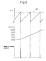
- FIG. 6 is a view of the amount of energy imparted
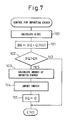
- FIG. 7 is a flow chart of control of imparting energy
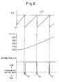
- FIG. 8 is a view of rich control of the air-fuel ratio
- FIG. 9 is a time chart of the change in the oxygen concentration and NO x concentration
- FIG. 10 is a view of the relationship between the amount of reducing agent to be supplied and the temperature of the NO x storing and decomposing catalyst
- FIG. 11 is a view of the rich control of the air-fuel ratio
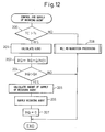
- FIG. 12 is a flow chart of control of the supply of the reducing agent
- FIG. 13 is a flow chart of processing for reducing the nitrate ions and nitrogen monoxide
- FIG. 14 is a view of the elapsed time
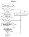
- FIG. 15 is a flow chart of control of the supply of the reducing agent
- FIG. 16 is an overview of another embodiment of a spark ignition type internal combustion engine
- FIG. 17 is a flow chart for control of the supply of the reducing agent
- FIG. 17 is a flow chart for control of the supply of the reducing agent
- FIG. 18 is an overview of still another embodiment of a spark ignition type internal combustion engine
- FIG. 19 is an overview of still another embodiment of a spark ignition type internal combustion engine
- FIG. 20 is an overview of a compression ignition type internal combustion engine
- FIGS. 21A and 21B are views of a particulate filter
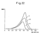
- FIG. 22 is a view of the amount of generation of smoke
- FIGS. 23A and 23B are views of the gas temperature etc. of a combustion chamber
- FIG. 24 is a view showing operating regions I and II
- FIG. 25 is a view of the air-fuel ratio A/F
- FIG. 26 is a view of the change of the throttle valve opening degree etc.
- FIG. 1 shows the case of application of the present invention to a spark ignition type internal combustion engine. Note that the present invention can also be applied to a compression ignition type internal combustion engine.
- 1 indicates an engine body, 2 a cylinder block, 3 a cylinder head, 4 a piston, 5 a combustion chamber, 6 an electrical control type fuel injector, 7 a spark plug, 8 an intake valve, 9 an intake port, 10 an exhaust valve, and 11 an exhaust port.
- Each intake port 9 is connected through a corresponding intake branch tube 12 to a surge tank 13, and the surge tank 13 is connected through an intake duct 14 to an air cleaner 15.
- the intake duct 14 is provided in it with a throttle valve 17 driven by a step motor 16, further, the intake duct 14 is provided inside it with an intake air sensor 18 for detecting a mass flow rate of intake air.
- the exhaust port 11 is connected through an exhaust manifold 19 to a catalytic converter 21 housing a NO x storing and decomposing catalyst 20.
- the exhaust manifold 19 and the surge tank 13 are connected through an exhaust gas recirculation (hereinafter referred to as an "EGR") passage 22, while the EGR passage 22 is provided with an electrical control type EGR control valve 23. Further, the EGR passage 22 is provided around it with a cooling device 24 for cooling the EGR gas flowing through the EGR passage 22. In the embodiment shown in FIG. 1, the engine cooling water is guided to the cooling device 24, and the engine cooling water cools the EGR gas.
- each fuel injector 6 is connected through a fuel supply pipe 25 to a fuel reservoir, that is, a common rail 26. This common rail 26 is supplied with fuel from an electrical control type variable discharge fuel pump 27.
- the fuel supplied into the common rail 26 is supplied through each fuel supply pipe 25 to a fuel injector 6.
- the common rail 26 is provided with a fuel pressure sensor 28 for detecting the fuel pressure in the common rail 26.
- the discharge of the fuel pump 27 is controlled based on the output signal of the fuel pressure sensor 28 so that the fuel in the common rail 26 becomes the target fuel pressure.
- An electronic control unit 30 is comprised of a digital computer provided with a ROM (read only memory) 32, RAM (random access memory) 33, CPU (microprocessor) 34, input port 35, and output port 36 connected by a bidirectional bus 31.
- the output signals of the intake air sensor 18 and fuel pressure sensor 28 are input through corresponding AD converters 37 to the input port 35.
- an accelerator pedal 40 has connected to it a load sensor 41 for generating an output voltage proportional to the amount of depression L of the accelerator pedal 40.
- the output voltage of the load sensor 41 is input through the corresponding AD converter 37 to the input port 35.
- the input port 35 has connected to it a crank angle sensor 42 generating an output pulse every time a crank shaft rotates for example by 30°.
- the output port 36 is connected through a corresponding drive circuit 38 to the fuel injector 6, spark plug 7, throttle valve drive step motor 16, EGR control valve 23, and fuel pump 27.
- the top face of the piston 4 is formed with a cavity 43.
- fuel F is injected toward the inside of the cavity 43 from the fuel injector 6. This fuel F is guided by the bottom surface of the cavity 43 and heads toward the spark plug 7. Due to this, the spark plug 7 has an air-fuel mixture formed around it. Next, this air-fuel mixture is ignited by the spark plug 7 and stratified combustion performed. At this time, the average air-fuel ratio in the combustion chamber 5 becomes lean. Therefore, the air-fuel ratio of the exhaust gas also becomes lean.
- fuel is injected divided into two between the initial period of the intake stroke and the end period of the compression stroke.
- the combustion chamber 5 is formed inside it with a lean air-fuel mixture expanding throughout the entire combustion chamber, while by the fuel injection at the end period of the compression stroke, the spark plug 7 is formed around it with an air-fuel mixture forming a spark.
- the average air-fuel ratio in the combustion chamber 5 becomes lean, therefore the air-fuel ratio of the exhaust gas also becomes lean.
- the NO x exhausted from the combustion chamber 5 is purified by the NO x storing and decomposing catalyst 20. Therefore, first, this NO x storing and decomposing catalyst 20 will be explained.
- the carrier of this NO x storing and decomposing catalyst 20 has a crystal structure of zirconium oxide ZrO 2 such as shown in FIG. 2A.
- part of the zirconium Zr in this crystal structure is replaced by a trivalent rare earth metal selected from lanthanum La, neodium Nd, and samarium Sm.
- the carrier has an alkali metal added to it.
- the crystal lattice is formed with oxygen defects with no oxygen O 2- present.
- the carrier has an alkali metal, for example, cesium Cs, added to it. Due to this cesium Cs, as shown in FIG. 2C, oxygen defects are given electrons e - . Oxygen defects given electrons e - have extremely strong basicity, therefore the oxygen defects given electrons e - will be referred to as "ultra-strong basic points" below.
- FIG. 2C shows the crystal structure of the carrier of the NO x storing and decomposing catalyst 20 used in the present invention.
- the carrier has this crystal structure over its entirety. Therefore, the NO x storing and decomposing catalyst 20 used in the present invention has countless ultrastrong basic points uniformly distributed across it.
- the carrier of the NO x storing and decomposing catalyst 20 used in the present invention has added to it aluminum Al for further increasing the heat stability, platinum Pt or another precious metal for promoting the oxidation reduction action, in particular the reduction action, and a metal such as cerium Ce for obtaining the function of a three-way catalyst.
- the exhaust gas when burning fuel under a lean air-fuel ratio, the exhaust gas contains nitrogen monoxide NO and nitrogen dioxide NO 2 or other nitrogen oxides NO x and excess oxygen O 2 .
- the majority of the nitrogen oxide NO x contained in the exhaust gas is nitrogen monoxide NO, therefore the mechanism of purification of the nitrogen monoxide NO will be explained as a typical example.
- the NO x storing and decomposing catalyst 20 used in the present invention has ultrastrong basic points. If such ultrastrong basic points are present, the acidic nitrogen monoxide NO is attracted to the ultrastrong basic points when the temperature of the NO x storing and decomposing catalyst 20 is low or high. As a result, nitrogen monoxide NO is trapped at the ultrastrong basic points of the NO x storing and decomposing catalyst 20 in the form of either FIG. 3A or 3B.
- the carrier of the NO x storing and decomposing catalyst 20 has countless ultrastrong basic points uniformly distributed across its entirety, so the NO x storing and decomposing catalyst 20 adsorbs an extremely large amount of nitrogen monoxide NO.
- the nitrogen monoxide NO in the exhaust gas is attracted by the ultrastrong basic points on the NO x storing and decomposing catalyst 20 and adsorbed and trapped at the ultrastrong basic points.
- the nitrogen monoxide NO is given electrons e - .
- the N-O bonds of the nitrogen monoxide NO are easily cleaved. In this case, the higher the temperature of the NO x storing and decomposing catalyst 20, the easier these N-O bonds are cleaved.
- nitrogen monoxide NO is adsorbed at ultrastrong basic points, after a while, the N-O bonds are cleaved to be disassociated to nitrogen N and oxygen O.
- the oxygen as shown in FIG. 3C, remains held at the ultrastrong basic points in the form of oxygen ions O - , and the nitrogen N is separated from the ultrastrong basic points and moves over the NO x storing and decomposing catalyst 20.
- the nitrogen N moving over the NO x storing and decomposing catalyst 20 bonds with the nitrogen N of the nitrogen monoxide NO adsorbed on the other ultrastrong basic points of the NO x storing and decomposing catalyst 20 or the other nitrogen N moving over the NO x storing and decomposing catalyst 20 to form nitrogen molecules N 2 and separates from the NO x storing and decomposing catalyst 20. In this way, the NO x is purified.
- the nitrogen monoxide NO is adsorbed at the ultrastrong basic points, after a while, the nitrogen monoxide NO is disassociated and the oxygen 0 is trapped on the ultrastrong basic points in the form of oxygen ions O - , so the ultrastrong basic points present on the NO x storing and decomposing catalyst 20 gradually are buried by oxygen ions O - . In this way, if the ultrastrong basic points are buried by oxygen ions O - , the nitrogen monoxide NO in the exhaust gas bonds with the nitrogen N of the nitrogen monoxide NO adsorbed at the ultrastrong basic points and as a result N 2 O is generated.
- the exhaust gas When burning fuel under a lean air-fuel ratio, the exhaust gas contains excess oxygen O 2 . Therefore, the nitrogen monoxide N-O - adsorbed at the ultrastrong basic points is oxidized by the excess oxygen O 2 . Due to this, nitrate ions NO 3 - are formed. That is, if the oxygen concentration in the exhaust gas is high, the reaction proceeds in a direction generating nitrate ions NO 3 - . Therefore, when burning fuel under a lean air-fuel ratio, nitrate ions NO 3 - are generated and held at part of the ultrastrong basic points.
- nitrate ions NO 3 - are produced by the nitrogen monoxide NO bonding with the oxygen ions O 2- forming crystals, while the generated nitrate ions NO 3 - are adsorbed on the zirconium Zr 4+ forming the crystals and are held on the NO x storing and decomposing catalyst 20 in that state.
- the nitrate ions NO 3 - decompose when the temperature become higher and are released in the form of nitrogen monoxide NO. Therefore, when the temperature of the NO x storing and decomposing catalyst 20 becomes higher, the NO x storing and decomposing catalyst 20 has almost no nitrate ions NO 3 - present on it any longer.
- the reference temperature when the NO x storing and decomposing catalyst 20 no longer has almost any nitrate ions NO 3 - present on it in this way, when the lower limit temperature of the NO x storing and decomposing catalyst 20 is referred to as the reference temperature, this reference temperature is determined by the NO x storing and decomposing catalyst 20. In the NO x storing and decomposing catalyst 20 used in the present invention, this reference temperature is substantially 600°C.
- the NO x storing and decomposing catalyst 20 when the temperature of the NO x storing and decomposing catalyst 20 is lower than this reference temperature, the NO x storing and decomposing catalyst 20 has nitrate ions NO 3 - generated on this. When the temperature of the NO x storing and decomposing catalyst 20 is higher than this reference temperature, the NO x storing and decomposing catalyst 20 no longer has almost any nitrate ions NO 3 - present on it.
- the excess oxygen O 2 contained in the exhaust gas causes the metal, for example, cerium Ce, carried on the NO x storing and decomposing catalyst 20 to be oxidized (Ce 2 O 3 +1/2O 2 ⁇ 2CeO 2 ) . Due to this, the NO x storing and decomposing catalyst 20 stores oxygen on this. This stored oxygen stably invades the crystal structure. Therefore, this stored oxygen does not separate from the NO x storing and decomposing catalyst 20 even if the NO x storing and decomposing catalyst 20 rises in temperature.
- the NO x storing and decomposing catalyst 20 when burning under a lean air-fuel ratio and the temperature of the NO x storing and decomposing catalyst 20 is higher than the reference temperature, the NO x storing and decomposing catalyst 20 holds O - or still not disassociated nitrogen monoxide NO at the ultrastrong basic points oxygen ions, and the NO x storing and decomposing catalyst 20 holds the stored oxygen. However, at this time, the NO x storing and decomposing catalyst 20 has almost no nitrate ions NO 3 - present on it.
- the NO x storing and decomposing catalyst 20 when burning fuel under a lean air-fuel ratio and the temperature of the NO x storing and decomposing catalyst 20 is lower than the reference temperature, the NO x storing and decomposing catalyst 20 holds oxygen ions O - or still not disassociated nitrogen monoxide NO at the ultrastrong basic points, while the NO x storing and decomposing catalyst 20 holds stored oxygen. However, at this time, a large amount of nitrate ions NO 3 - is generated on the NO x storing and decomposing catalyst 20.
- the NO x storing and decomposing catalyst 20 when the temperature of the NO x storing and decomposing catalyst 20 is lower than the reference temperature, the nitrogen monoxide NO in the exhaust gas changes to nitrate ions NO 3 - on the NO x storing and decomposing catalyst 20, therefore at this time, the NO x storing and decomposing catalyst 20 has a large amount of nitrate ions NO 3 - present on it, but the oxygen ions O - held on the NO x storing and decomposing catalyst 20 are comparatively small.
- the nitrate ions NO 3 - end up immediately breaking up even if formed, therefore the NO x storing and decomposing catalyst 20 does not have almost any nitrate ions NO 3 - on it.
- the disassociation action of the nitrogen monoxide NO adsorbed on the ultrastrong basic points on the NO x storing and decomposing catalyst 20 is actively performed, therefore the amount of the oxygen ions O - trapped at the ultrastrong basic points gradually increases.
- This restoration treatment changes in accordance with the temperature of the NO x storing and decomposing catalyst 20, therefore first the case where the temperature of the NO x storing and decomposing catalyst 20 is higher than the reference temperature will be explained.
- the ultrastrong basic points of the NO x storing and decomposing catalyst 20 hold the disassociated oxygen ions O - . Therefore, if continuously burning fuel under a lean air-fuel ratio, the ultrastrong basic points of the NO x storing and decomposing catalyst 20 gradually are buried by oxygen ions O - , therefore the number of the ultrastrong basic points which the nitrogen monoxide NO can be adsorbed at gradually is reduced. As a result, the NO x purification rate gradually falls.
- the ultrastrong basic points are positioned between electrically plus metal ions, therefore electrically minus oxygen ions O - are easily held between these metal ions.
- the bonding force between the oxygen ions O - and metal ions is weak, therefore the oxygen ions O - are extremely unstable in state. If part of the oxygen ions O - in the oxygen ions held at the ultrastrong basic points is purged from the ultrastrong basic points, this purging action induces the remaining oxygen ions O - held at the ultrastrong basic points to be purged all at once. However, at this time, the oxygen stored at the NO x storing and decomposing catalyst 20 is not purged.
- various types of energy may be considered as the energy to be imparted. For example, if making the exhaust gas temperature or temperature of the NO x storing and decomposing catalyst 20 a high temperature, the oxygen ions O - held on the NO x storing and decomposing catalyst 20 are purged. Therefore, as the energy imparted, it is possible to use heat energy.
- the oxygen ions O - held at the NO x storing and decomposing catalyst 20 become easier to separate when the temperature of the NO x storing and decomposing catalyst 20 becomes higher. Therefore, as shown in FIG. 4, the amount of energy E necessary for puring part of the oxygen ions O - held on the O x storing and decomposing catalyst 20 from the NO x storing and decomposing catalyst 20 becomes smaller the higher the temperature TC of the NO x storing and decomposing catalyst 20.
- the nitrogen monoxide NO included in the exhaust gas is held in that form or in the form of oxygen ions O - after disassociation on the NO x storing and decomposing catalyst 20. Therefore, the total of the oxygen ions O - and nitrogen monoxide NO held on the NO x storing and decomposing catalyst 20 becomes the cumulative amount of the nitrogen monoxide NO contained in the exhaust gas.
- the amount of the nitrogen monoxide NO contained in the exhaust gas is determined in accordance with the operating state of the engine.
- FIG. 5 shows the amount Q(NO) of the nitrogen monoxide exhausted from the engine per unit time found from experiments in the form of a map as a function of the engine load L and engine speed N.
- the total of the oxygen ions O - and nitrogen monoxide NO held at the NO x storing and decomposing catalyst 20 can be estimated from the cumulative value of the amount Q(NO) of the nitrogen monoxide shown in FIG. 5. Therefore, in this embodiment of the present invention, the cumulative value of the amount Q(NO) of the nitrogen monoxide shown in FIG. 5 is used as the estimated total of the oxygen ions O - and nitrogen monoxide NO held in the NO x storing and decomposing catalyst 20.
- FIG. 6 shows the relationship between the cumulative value ⁇ Q of the Q(NO) shown in FIG. 5, the temperature TC of the NO x storing and decomposing catalyst 20, and the imparted energy when the temperature of the NO x storing and decomposing catalyst 20 is higher than the reference temperature.
- FIG. 7 shows the routine for control of imparting energy.
- step 100 the amount Q(NO) of nitrogen monoxide is calculated from the map shown in FIG. 5.
- step 101 ⁇ Q is incremented by Q(NO) to calculate the cumulative amount ⁇ Q.
- step 102 it is judged if the cumulative amount ⁇ Q exceeds the set amount QX.
- step 103 the amount of energy to be imparted is calculated.
- step 104 the energy is imparted.
- step 105 ⁇ Q is cleared.
- the reducing agent so as to make air-fuel ratio in the combustion chamber 5 or the air-fuel ratio of the exhaust gas rich periodically, for example every predetermined period, every time the cumulative value of the speed of the engine exceeds a set value, or every time the running distance of the vehicle exceeds a certain distance.
- the reducing agent fuel containing hydrocarbons etc.
- the fuel acting as the reducing agent is the amount of fuel forming an excess with respect to the stoichiometric air-fuel ratio. That is, referring to FIG. 8, the part at the rich side of the stoichiometric air-fuel ratio shown by the hatching shows the amount Qr of the reducing agent.
- This reducing agent may be supplied in the combustion chamber 5 by increasing the amount of injection from the fuel injector 6 and may be supplied into the exhaust gas exhausted from the combustion chamber 5.
- FIG. 9 shows the change in the oxygen concentration (%) and change in the NO x concentration (ppm) in the exhaust gas flowing out from the NO x storing and decomposing catalyst 20 when the air-fuel ratio A/F of the exhaust gas flowing into the NO x storing and decomposing catalyst 20 is maintained lean and when it is made rich in a spike.
- the NO x storing and decomposing catalyst 20 when burning fuel under a lean air-fuel ratio and the temperature of the NO x storing and decomposing catalyst 20 is higher than the reference temperature, the NO x storing and decomposing catalyst 20 holds the oxygen ions O - and nitrogen monoxide NO, and the NO x storing and decomposing catalyst 20 holds the stored oxygen.
- the NO x storing and decomposing catalyst 20 has almost no nitrate ions NO 3 - present on it.
- the NO x storing and decomposing catalyst 20 used in the present invention if the air-fuel ratio A/F is switched from lean to rich, the oxygen ions O - held at the NO x storing and decomposing catalyst 20 are separated, so at this time, the oxygen concentration in the exhaust gas flowing out from the NO x storing and decomposing catalyst 20 will not become zero due to the effects of the oxygen ions O - separated as shown in FIG. 9.
- FIG. 10 shows the relationship between the amount Qr of reducing agent expressed by the equivalent ratio required when making the air-fuel ratio rich to restore the purification performance of the NO x storing and decomposing catalyst 20 and the temperature TC of the NO x storing and decomposing catalyst 20.
- the amount of the reducing agent necessary for reducing the nitrogen monoxide NO produced in the interval from making the air-fuel ratio in the combustion chamber 5 or the air-fuel ratio of the exhaust gas rich once to when the air-fuel ratio in the combustion chamber 5 or the air-fuel ratio of the exhaust gas is again made rich when trying to reduce the nitrogen monoxide NO by a reducing agent is called the amount Qr of reducing agent where the equivalent ratio of the reducing agent/NO is 1.
- the equivalent ratio of the amount of reducing agent becomes smaller than 1.0.
- the amount Qr of reducing agent when making the air-fuel ratio in the combustion chamber 5 or the air-fuel ratio of the exhaust gas rich for purging the oxygen ions O - held on the NO x storing and decomposing catalyst 20 when the temperature TC of the NO x storing and decomposing catalyst 20 is higher than the reference temperature Ts is smaller than the amount of the reducing agent necessary for reducing the nitrogen monoxide NO produced in the interval from when the air-fuel ratio in the combustion chamber 5 or the air-fuel ratio of the exhaust gas is made rich the previous time to when the air-fuel ratio in the combustion chamber 5 or the air-fuel ratio of the exhaust gas is made rich the current time, that is, the amount of the reducing agent with an equivalent ratio of 1.0.
- the amount Qr of the reducing agent to be supplied when making the air-fuel ratio rich is required to be only about one-third of the amount of the reducing agent necessary for reducing the nitrogen monoxide NO contained in the exhaust gas flowing into the NO x storing and decomposing catalyst 20, that is, the amount of the reducing agent with an equivalent ratio of 1.0, when the temperature TC of the NO x storing and decomposing catalyst 20 is about 800°C, only about one-quarter of the amount of the reducing agent necessary for reducing the nitrogen monoxide NO contained in the exhaust gas flowing into the NO x storing and decomposing catalyst 20 when the temperature TC of the NO x storing and decomposing catalyst 20 is about 900°C, and only about one-sixth of the amount of the reducing agent necessary for reducing the nitrogen monoxide NO contained in the exhaust gas flowing into the NO x storing and decomposing catalyst 20 when the temperature TC of the NO x storing and decomposing catalyst 20 is about 1000°C.
- the amount Qr of the reducing agent supplied when making the air-fuel ratio rich is made the amount of reducing agent with an equivalent ratio of 1.0 or more. That is, as explained above, even when burning fuel under a lean air-fuel ratio and the temperature TC of the NO x storing and decomposing catalyst 20 is lower than the reference temperature Ts, the NO x storing and decomposing catalyst 20 holds oxygen ions O - and nitrogen monoxide NO on it in points and further the NO x storing and decomposing catalyst 20 holds the stored oxygen.
- the nitrogen monoxide NO in the exhaust gas changes to nitrate ions NO 3 - on the NO x storing and decomposing catalyst 20, therefore the NO x storing and decomposing catalyst 20 has a large amount of nitrate ions NO 3 - present on it, but there are little oxygen ions O - and nitrogen monoxide NO held on the NO x storing and decomposing catalyst 20. That is, when the temperature TC of the NO x storing and decomposing catalyst 20 is lower than the reference temperature Ts, the nitrogen monoxide NO in the exhaust gas is mostly stored in the form of nitrate ions NO 3 - in the NO x storing and decomposing catalyst 20. Due to this, the NO x in the exhaust gas is purified.
- the nitrate ions NO 3 - and nitrogen monoxide NO stored in the NO x storing and decomposing catalyst 20 are reduced.
- the efficiency of reduction of nitrate ions NO 3 - by the reducing agent is not 100 percent, to reduce the nitrate ions NO 3 - stored in the NO x storing and decomposing catalyst 20, a greater amount of reducing agent is required than the amount of reducing agent necessary for reducing the nitrate ions NO 3 - and nitrogen monoxide NO stored in the NO x storing and decomposing catalyst 20. Therefore, as explained above, the amount Qr of the reducing agent supplied when making the air-fuel ratio rich is made an amount of reducing agent with an equivalent ratio of 1.0 or more.
- the amount Q(NO) of nitrogen monoxide calculated from the map shown in FIG. 5 is cumulatively added. As shown in FIG. 11, when this cumulative amount ⁇ Q(NO) exceeds the allowable amount MAX, the air-fuel ratio A/F is temporarily made rich. Due to this, the purification performance of the NO x storing and decomposing catalyst 20 is restored. Comparing FIG. 11 and FIG. 8, it is learned that the amount Qr of reducing agent at this time is far greater than the case shown in FIG. 8. Further, it is learned that the amount Qr of the reducing agent at this time does not depend on the temperature TC of the NO x storing and decomposing catalyst 20.
- FIG. 12 shows a routine for control of the supply of the reducing agent.
- step 200 it is judged if the temperature TC of the NO x storing and decomposing catalyst 20 is higher than the reference temperature Ts.
- the routine proceeds to step 201, where the oxygen held in the NO x storing and decomposing catalyst 20 is purged. That is, at step 201, the amount Q(NO) of nitrogen monoxide is calculated from the map shown in FIG. 5.
- step 203 ⁇ Q is incremented by Q(NO) to calculate the cumulative amount ⁇ Q.
- step 204 it is judged if the cumulative amount ⁇ Q exceeds the set amount QX.
- the routine proceeds to step 205, where the amount of reducing agent to be supplied is calculated.
- step 206 the reducing agent is supplied to make the air-fuel ratio rich.
- ⁇ Q is cleared.
- step 200 when it is judged at step 200 that TC ⁇ Ts, the routine proceeds to step 208, where the nitrate ions NO 3 - and nitrogen monoxide NO stored in the NO x storing and decomposing catalyst 20 are reduced by NO reduction processing.
- This NO reduction processing is shown in FIG. 13. Referring to FIG. 13, first at step 210, the amount Q(NO) of nitrogen monoxide is cumulatively added from the map shown in FIG. 5. Next, at step 211, ⁇ Q(NO) is incremented by Q(NO) so as to calculate the cumulative amount ⁇ Q(NO). Next, at step 212, it is judged if the cumulative amount ⁇ Q(NO) has exceeded the allowable amount MAX.
- step 213 the amount of reducing agent to be supplied is calculated.
- step 214 the reducing agent is supplied to make the air-fuel ratio rich.
- step 215 ⁇ Q(NO) is cleared.
- the time interval tX from when making the air-fuel ratio in the combustion chamber 5 or the air-fuel ratio of the exhaust gas rich to purge the oxygen ions O - stored in the NO x storing and decomposing catalyst 20 to when next making the air-fuel ratio in the combustion chamber 5 or the air-fuel ratio of the exhaust gas rich is increased the higher the temperature TC of the NO x storing and decomposing catalyst 20.
- FIG. 15 shows a routine for control of the supply of the reducing agent for working this third embodiment.
- step 220 it is judged if the temperature TC of the NO x storing and decomposing catalyst 20 is higher than a reference temperature Ts.
- the routine proceeds to step 221, where the time ⁇ t from the previous processing cycle to the current processing cycle is added to the time ⁇ t. Due to this, the elapsed time ⁇ t is calculated.
- step 222 the elapsed time tX to be targeted is calculated from FIG. 13.
- step 223 it is judged if the elapsed time ⁇ t has exceeded the target elapsed time tX.
- the routine proceeds to step 224, where the amount of reducing agent to be supplied is calculated.
- step 225 the reducing agent is supplied to make the air-fuel ratio rich, then at step 226, ⁇ t is cleared.
- step 220 when it is judged at step 220 that TC ⁇ Ts, the routine proceeds to step 208, where the processing for reducing NO shown in FIG. 13 is executed.
- FIG. 16 shows a fourth embodiment.
- the part of the exhaust pipe 43 downstream of the NO x storing and decomposing catalyst 20 is provided inside it with a NO x concentration sensor 44 for detecting the NO x concentration in the exhaust gas passing through the NO x storing and decomposing catalyst 20.
- the ultrastrong basic points of the NO x storing and decomposing catalyst 20 are not buried by oxygen ions O - , the NO x contained in the exhaust gas is trapped by the NO x storing and decomposing catalyst 20, so the exhaust gas flowing out from the NO x storing and decomposing catalyst 20 does not contain much NO x at all.
- the amount of NO x passing straight through the NO x storing and decomposing catalyst 20 without being trapped by the NO x storing and decomposing catalyst 20 gradually increases.
- FIG. 17 shows the routine for control of the supply of the reducing agent for working this fourth embodiment.
- step 230 the NO x concentration De in the exhaust gas flowing out from the NO x storing and decomposing catalyst 20 is detected by the NO x concentration sensor 44.
- step 231 it is judged if the NO x concentration De detected by the NO x concentration sensor 44 has become larger than the allowable value DX.
- the routine proceeds to step 232, it is judged if the temperature TC of the NO x storing and decomposing catalyst 20 is higher than the reference temperature Ts.
- step 233 the amount of reducing agent to be supplied is calculated.
- step 232 when it is judged at step 232 that TC ⁇ Ts, the routine proceeds to step 235, where the amount of reducing agent to be supplied is calculated.
- FIG. 18 shows still another embodiment.
- the NO x storing and decomposing catalyst 50 is carried at the inside walls of the combustion chamber 5 such as the inside walls of the cylinder head 3 and top face of the piston 4, or the NO x storing and decomposing catalyst 51 is carried on the inside walls of the exhaust passage such as the inside walls of the exhaust port 11 and inside walls of the exhaust manifold 19.
- the combustion gas or burned gas in the combustion chamber 5 contacts the NO x storing and decomposing catalyst 50 whereupon the nitrogen oxide contained in these combustion gas or burned gas, mainly nitrogen monoxide NO, is adsorbed at the NO x storing and decomposing catalyst 50, then disassociated to nitrogen N and oxygen O.
- the NO x storing and decomposing catalyst 51 is carried on the inside walls of the exhaust passage, the exhaust gas exhausted from the combustion chamber 5 contacts the NO x storing and decomposing catalyst 51, whereupon the nitrogen monoxide NO contained in this exhaust gas is adsorbed at the NO x storing and decomposing catalyst 51, then is disassociated to nitrogen N and oxygen O.
- the exhaust manifold 19 upstream of the NO x storing and decomposing catalyst 20 is provided inside it with a reducing agent feed valve 52.
- this reducing agent feed valve 52 supplies a reducing agent inside the exhaust gas.
- FIG. 20 shows the case of application of the present invention to a compression ignition type internal combustion engine. Note that in FIG. 20, parts similar to those of the spark ignition type internal combustion engine shown in FIG. 1 are shown by the same reference numerals.
- 1 indicates an engine body, 5 a combustion chamber of each cylinder, 6 an electrical control type fuel injector for injecting fuel into each combustion chamber 5, 13a an intake manifold, and 19 an exhaust manifold.
- the intake manifold 13a is connected through the intake duct 14 to the outlet of the compressor 53a of the exhaust turbocharger 53, while the inlet of the compressor 53a is connected to the air cleaner 15.
- the intake duct 14 is provided inside it with a throttle valve 17.
- the intake duct 14 is provided around it with a cooling device 54 for cooling the intake air flowing through the intake duct 14.
- the exhaust manifold 19 is connected with the inlet of an exhaust turbine 53b of the exhaust turbocharger 53, while the outlet of the exhaust turbine 53b is connected to a catalytic converter 21 housing the NO x storing and decomposing catalyst 20.
- the outlet of the collecting portion of the exhaust manifold 19 is provided with a reducing agent feed valve 55 for supplying a reducing agent comprised of for example hydrocarbons for making the air-fuel ratio of the exhaust gas rich.
- the exhaust manifold 19 and the intake manifold 13a are connected with each other via an EGR passage 22.
- the EGR passage 22 is provided inside it with an electrical control type EGR control valve 23.
- each fuel injector 6 is connected through a fuel supply pipe 25 to a common rail 26.
- This common rail 26 is supplied with fuel from an electrical control type variable discharge fuel pump 27.
- the amount of the periodically supplied reducing agent is made smaller than the amount of the reducing agent necessary for reducing the NO x flowing into the NO x storing and decomposing catalyst 20 in the interval from when the reducing agent is supplied the previous time to when the reducing agent is supplied the current time.
- the amount of the periodically supplied reducing agent is made larger than the amount of the reducing agent necessary for reducing the NO x flowing into the NO x storing and decomposing catalyst 20 in the interval from when the reducing agent is supplied the previous time to when the reducing agent is supplied the current time.
- FIG. 21A and 21B show the structure of this particulate filter.
- FIG. 21A is a front view of a particulate filter
- FIG. 21B is a side sectional view of a particulate filter.
- the particulate filter forms a honeycomb structure and is provided with a plurality of exhaust flow passages 60 and 61 extending in parallel with each other.
- These exhaust flow passages are comprised of exhaust gas inflow passages 60 with downstream ends closed by plugs 62 and exhaust gas outflow passages 61 with upstream ends closed by plugs 63.
- the hatched portions indicate plugs 63.
- the exhaust gas inflow passages 60 and exhaust gas outflow passages 61 are alternately arranged via thin partitions 64.
- the exhaust gas inflow passages 60 and exhaust gas outflow passages 61 are arranged so that each exhaust gas inflow passage 60 is surrounded by four exhaust gas outflow passages 61 and so that each exhaust gas outflow passage 61 is surrounded by four exhaust gas inflow passages 60.
- the particulate filter is formed from a porous material such as for example cordierite. Therefore, the exhaust gas flowing into the exhaust gas inflow passages 60, as shown by the arrows in FIG. 21B, passes through the surrounding partitions 64 and flows out into the neighboring exhaust gas outflow passages 61.
- the peripheral walls of the exhaust gas inflow passages 60 and exhaust gas outflow passages 61 that is, the two side surfaces of the partitions 64 and the inside walls of the holes in the partitions 64, are formed with a layer of a NO x storing and decomposing catalyst.
- the air-fuel ratio of the exhaust gas is made rich.
- the particulate contained in the exhaust gas is trapped by the particulate filter, and the trapped particulate is successively burned by the heat of the exhaust gas.
- a reducing agent is supplied and the exhaust gas temperature is raised. Due to this, the deposited particulate is ignited and burned.
- the amount of generation of smoke peaks when the EGR rate is slightly lower than 50 percent. In this case, if making the EGR rate substantially 55 percent or more, almost no smoke is generated any longer.
- the curve B of FIG. 22 when slightly cooling the EGR gas, the amount of generation of smoke peaks when the EGR rate is slightly higher than 50 percent. In this case, if making the EGR rate substantially 65 percent or more, almost no smoke is generated any longer.
- the curve C in FIG. 22 when not forcibly cooling the EGR gas, the amount of generation of smoke peaks when the EGR rate is near 55 percent. In this case, if making the EGR rate substantially 70 percent or more, almost no smoke is generated any longer.
- the reason why making the EGR gas rate 55 percent or more results in no smoke being generated any longer in this way is that the endothermic action of the EGR gas keeps the gas temperature of the fuel and its surroundings at the time of combustion from being that high, that is, low temperature combustion is performed and, as a result, hydrocarbons do not grow to soot.
- This low temperature combustion has the characteristic of enabling a reduction in the amount of generation of NO x while suppressing the generation of smoke regardless of the air-fuel ratio. That is, if the air-fuel ratio is made rich, the fuel becomes in excess, but the combustion temperature is suppressed to a low temperature, so the excess fuel does not grow to soot, therefore smoke is never generated. Further, at this time, only an extremely small amount of NO x is also produced. On the other hand, when the average air-fuel ratio is lean or when the air-fuel ratio is the stoichiometric air-fuel ratio, the higher the combustion temperature, the smaller the amount of soot produced, but under low temperature combustion, the combustion temperature is suppressed to a low temperature, so no smoke is generated at all. The amount of NO x generated is only extremely small.
- the solid line of FIG. 23A shows the relationship between the average gas temperature Tg in the combustion chamber 5 and the crank angle at the time of low temperature combustion
- the broken line of FIG. 23A shows the relationship between the average gas temperature Tg in the combustion chamber 5 and the crank angle at the time of ordinary combustion
- the solid line of FIG. 23B shows the relationship between the gas temperature Tf of the fuel and its surroundings and the crank angle at the time of low temperature combustion
- the broken line of FIG. 23B shows the relationship between the gas temperature Tf of the fuel and its surroundings and the crank angle at the time of ordinary combustion.
- the average gas temperature Tg in the combustion chamber 5 near compression top dead center becomes higher when low temperature combustion is being performed compared with when ordinary combustion is being performed.
- the temperature of the burned gas in the combustion chamber 5 after combustion ends becomes higher when low temperature combustion is being performed compared with when an ordinary combustion is being performed, therefore when low temperature combustion is performed, the exhaust gas temperature becomes higher.
- region I indicates first combustion where the amount of inert gas of the combustion chamber 5 is greater than the amount of inert gas where the amount of generation of soot peaks. That is, it shows the operating region where low temperature combustion can be performed.
- Region II indicates second combustion where the amount of inert gas in the combustion chamber is smaller than the amount of inert gas where the amount of generation of soot peaks. That is, it shows the operating region where only ordinary combustion can be performed.
- FIG. 25 shows the target air-fuel ratio A/F in the case of low temperature combustion in the operating region I
- FIG. 26 shows the opening degree of the throttle valve 17 in accordance with the required torque TQ, the opening degree of the EGR control valve 23, the EGR rate, the air-fuel ratio, the injection start timing ⁇ S, the injection end timing ⁇ E, and the injection amount when performing low temperature combustion in the operating region I.
- FIG. 26 also shows the opening degree etc. of the throttle valve 17 in the case of ordinary combustion performed in the operating region II.
Landscapes
- Engineering & Computer Science (AREA)
- Chemical & Material Sciences (AREA)
- Combustion & Propulsion (AREA)
- General Engineering & Computer Science (AREA)
- Mechanical Engineering (AREA)
- Chemical Kinetics & Catalysis (AREA)
- Health & Medical Sciences (AREA)
- Biomedical Technology (AREA)
- Environmental & Geological Engineering (AREA)
- Analytical Chemistry (AREA)
- General Chemical & Material Sciences (AREA)
- Oil, Petroleum & Natural Gas (AREA)
- Toxicology (AREA)
- Exhaust Gas After Treatment (AREA)
- Exhaust Gas Treatment By Means Of Catalyst (AREA)
- Processes For Solid Components From Exhaust (AREA)
- Electrical Control Of Air Or Fuel Supplied To Internal-Combustion Engine (AREA)
- Combined Controls Of Internal Combustion Engines (AREA)
Abstract
Description
Claims (29)
- An exhaust purification method of an internal combustion engine wherein combustion gas or burned gas in an engine combustion chamber or an exhaust gas exhausted from the engine combustion chamber is brought into contact with a NOx storing and decomposing catalyst, nitrogen oxide contained in these gases is adsorbed at the NOx storing and decomposing catalyst and diassociated to nitrogen and oxygen when burning fuel under a lean air-fuel ratio, the diassociated oxygen is held on the NOx storing and decomposing catalyst at this time, the disassociated nitrogen is separated from the NOx storing and decomposing catalyst, an energy necessary for purging part of the oxygen held on the NOx storing and decomposing catalyst from the NOx storing and decomposing catalyst is imparted to the NOx storing and decomposing catalyst to purge part of the oxygen held on the NOx storing and decomposing catalyst from the NOx storing and decomposing catalyst, and this purging action induces the remaining oxygen held on the NOx storing and decomposing catalyst to be purged from the NOx storing and decomposing catalyst.
- An exhaust purification method of an internal combustion engine as set forth in claim 1, wherein when the temperature of the NOx storing and decomposing catalyst is higher than a reference temperature determined by the NOx storing and decomposing catalyst, the remaining oxygen held on the NOx storing and decomposing catalyst is purged from the NOx storing and decomposing catalyst if imparting energy necessary for making part of the oxygen held on the NOx storing and decomposing catalyst separate from the NOx storing and decomposing catalyst to the NOx storing and decomposing catalyst.
- An exhaust purification method of an internal combustion engine as set forth in claim 1, wherein oxygen defects formed in the carrier of the NOx storing and decomposing catalyst are given electrons, ultrastrong basic points are formed, and nitrogen monoxide contained in the gas is adsorbed at the ultrastrong basic points and disassociated to nitrogen and oxygen.
- An exhaust purification method of an internal combustion engine as set forth in claim 3, wherein the carrier of the NOx storing and decomposing catalyst has a crystal structure of zirconium oxide, part of the zirconium in this crystal structure is replaced by a trivalent rare earth metal selected from lanthanum, neodium, and samarium, the carrier has an alkali metal added to it, oxygen defects are formed by replacing the zirconium forming the zirconium oxide by a trivalent rare earth metal, and an alkali metal is used to given the oxygen defects electrons.
- An exhaust purification method of an internal combustion engine as set forth in claim 1, wherein oxygen held on the NOx storing and decomposing catalyst is periodically purged from the NOx storing and decomposing catalyst by said energy being periodically imparted to the NOx storing and decomposing catalyst.
- An exhaust purification method of an internal combustion engine as set forth in claim 5, wherein said energy is imparted to the NOx storing and decomposing catalyst when the total of the nitrogem monoxide adsorbed at the NOx storing and decomposing catalyst exceeds a predetermined set value.
- An exhaust purification method of an internal combustion engine as set forth in claim 5, wherein the amount of energy imparted to the NOx storing and decomposing catalyst is reduced the higher the temperature of the NOx storing and decomposing catalyst.
- An exhaust purification method of an internal combustion engine as set forth in claim 5, wherein the time interval from when the NOx storing and decomposing catalyst is imparted with energy to when it is next imparted with energy is increased the higher the temperature of the NOx storing and decomposing catalyst.
- An exhaust purification method of an internal combustion engine as set forth in claim 5, wherein the NOx concentration in the exhaust gas passing through the NOx storing and decomposing catalyst is detected and said energy is imparted to the NOx storing and decomposing catalyst when this NOx concentration exceeds an allowable value.
- An exhaust purification method of an internal combustion engine as set forth in claim 5, wherein said energy is heat energy.
- An exhaust purification method of an internal combustion engine as set forth in claim 5, wherein said energy is generated by a reducing agent supplied in the combustion chamber or in the exhaust gas, and the reducing agent is supplied in the combustion chamber or in the exhaust gas and the air-fuel ratio of the combustion chamber or the air-fuel ratio of the exhaust gas is made rich when purging the oxygen held on the NOx storing and decomposing catalyst from the NOx storing and decomposing catalyst.
- An exhaust purification method of an internal combustion engine as set forth in claim 11, wherein the amount of reducing agent when the air-fuel ratio of the combustion chamber or the air-fuel ratio of the exhaust gas is made rich for purging oxygen held on the NOx storing and decomposing catalyst is smaller than the amount of the reducing agent necessary for reducing the nitrogen monoxide generated in the time interval from when the air-fuel ratio of the combustion chamber or the air-fuel ratio of the exhaust gas is made rich the previous time to when the air-fuel ratio of the combustion chamber or the air-fuel ratio of the exhaust gas is made rich the current time.
- An exhaust purification method of an internal combustion engine as set forth in claim 12, wherein the amount of reducing agent supplied for purging the oxygen held on the NOx storing and decomposing catalyst is reduced the higher the temperature of the NOx storing and decomposing catalyst.
- An exhaust purification method of an internal combustion engine as set forth in claim 11, wherein the time interval from when the air-fuel ratio of the combustion chamber or the air-fuel ratio of the exhaust gas is made rich for purging the oxygen held on the NOx storing and decomposing catalyst to when the air-fuel ratio of the combustion chamber or the air-fuel ratio of the exhaust gas is made rich the next time is increased the higher the temperature of the NOx storing and decomposing catalyst.
- An exhaust purification apparatus of an internal combustion engine wherein a NOx storing and decomposing catalyst, adsorbing nitrogen oxide contained in combustion gas or burned gas and diassociating it to nitrogen and oxygen when burning fuel under a lean air-fuel ratio and, at this time, holding the disassociated oxygen and separating the disassociated nitrogen, is arranged in an engine combustion chamber or engine exhaust passage, energy imparting means for imparting to the NOx storing and decomposing catalyst the energy necessary for purging part of the oxygen held on the NOx storing and decomposing catalyst is provided, the energy necessary for purging part of the oxygen held on the NOx storing and decomposing catalyst from the NOx storing and decomposing catalyst is imparted to the NOx storing and decomposing catalyst to purge part of the oxygen held on the NOx storing and decomposing catalyst from the NOx storing and decomposing catalyst, and this purging action induces the remaining oxygen held on the NOx storing and decomposing catalyst to be purged from the NOx storing and decomposing catalyst.
- An exhaust purification apparatus of an internal combustion engine as set forth in claim 15, wherein when the temperature of the NOx storing and decomposing catalyst is higher than a reference temperature determined by the NOx storing and decomposing catalyst, the remaining oxygen held on the NOx storing and decomposing catalyst is purged from the NOx storing and decomposing catalyst if imparting energy necessary for making part of the oxygen held on the NOx storing and decomposing catalyst separate from the NOx storing and decomposing catalyst to the NOx storing and decomposing catalyst.
- An exhaust purification apparatus of an internal combustion engine as set forth in claim 15, wherein a carrier of the NOx storing and decomposing catalyst is formed with oxygen defects, the oxygen defects are given electrons, ultrastrong basic points are formed, and nitrogen monoxide contained in the combustion gas or burned gas is adsorbed on the ultrastrong basic points and disassociated to nitrogen and oxygen.
- An exhaust purification apparatus of an internal combustion engine as set forth in claim 17, wherein the carrier of the NOx storing and decomposing catalyst has a crystal structure of zirconium oxide, part of the zirconium in this crystal structure is replaced by a trivalent rare earth metal selected from lanthanum, neodium, and samarium, the carrier has an alkali metal added to it, oxygen defects are formed by replacing the zirconium forming the zirconium oxide with a trivalent rare earth metal, and an alkali metal is used to give oxygen defects electrons.
- An exhaust purification apparatus of an internal combustion engine as set forth in claim 15, wherein said energy is generated by a reducing agent supplied to the combustion chamber or exhaust gas, and the oxygen held on the NOx storing and decomposing catalyst is periodically purged from the NOx storing and decomposing catalyst by having a reducing agent periodically supplied to the combustion chamber or exhaust gas and having the air-fuel ratio of the combustion chamber or the air-fuel ratio of the exhaust gas periodically be made rich.
- An exhaust purification apparatus of an internal combustion engine as set forth in claim 19, wherein the amount of the reducing agent when the oxygen held on the NOx storing and decomposing catalyst is purged by having the air-fuel ratio of the combustion chamber or the air-fuel ratio of the exhaust gas made rich is made smaller than the amount of the reducing agent necessary for reducing the nitrogen monoxide generated in the time interval from when the air-fuel ratio of the combustion chamber or the air-fuel ratio of the exhaust gas is made rich the previous time to when the air-fuel ratio of the combustion chamber or the air-fuel ratio of the exhaust gas is made rich the current time.
- An exhaust purification apparatus of an internal combustion engine as set forth in claim 20, wherein the amount of reducing agent supplied for purging the oxygen held on the NOx storing and decomposing catalyst is reduced the higher the temperature of the NOx storing and decomposing catalyst.
- An exhaust purification apparatus of an internal combustion engine as set forth in claim 19, wherein when the total amount of the nitrogen monoxide adsorbed on the NOx storing and decomposing catalyst exceeds a predetermined set amount, the reducing agent is supplied in the combustion chamber or exhaust gas and the air-fuel ratio of the combustion chamber or the air-fuel ratio of the exhaust gas is made rich.
- An exhaust purification apparatus of an internal combustion engine as set forth in claim 19, wherein the time interval from when the air-fuel ratio of the combustion chamber or the air-fuel ratio of the exhaust gas is made rich for purging the oxygen held on the NOx storing and decomposing catalyst to when the air-fuel ratio of the combustion chamber or the air-fuel ratio of the exhaust gas is next made rich is increased the higher the temperature of the NOx storing and decomposing catalyst.
- An exhaust purification apparatus of an internal combustion engine as set forth in claim 19, wherein a NOx concentration sensor for detecting the NOx concentration in the exhaust gas passing through the NOx storing and decomposing catalyst is provided, and a reducing agent is supplied in the combustion chamber or exhaust gas and the air-fuel ratio of the combustion chamber or the air-fuel ratio of the exhaust gas is made rich when the NOx concentration detected by the NOx concentration sensor exceeds an allowable value.
- An exhaust purification apparatus of an internal combustion engine as set forth in claim 15, wherein the engine exhaust passage is provided with a particulate filter for treating the particulate in the exhaust gas, and the NOx storing and decomposing catalyst is carried on the particulate filter.
- An exhaust purification apparatus in an internal combustion engine providing an engine exhaust passage with an exhaust purification catalyst and making the air-fuel ratio of an exhaust gas periodically rich in a spike when continuously burning under a lean air-fuel ratio so as to purify the NOx in the exhaust gas, where a NOx storing and decomposing catalyst diassociating nitrogen monoxide and holding oxygen when burning fuel under a lean air-fuel ratio is used as an exhaust purification catalyst, a reducing agent is periodically supplied in the engine combustion chamber or in the engine exhaust passage upstream of the NOx storing and decomposing catalyst so as to periodically make the air-fuel ratio of the exhaust gas rich in a spike, and the amount of the periodically supplied reducing agent is smaller than the amount of the reducing agent necessary for reducing the nitrogen monoxide flowing into the NOx storing and decomposing catalyst in the interval from when the reducing agent is supplied the previous time to when the reducing agent is supplied the current time.
- An exhaust purification apparatus of an internal combustion engine as set forth in claim 26, wherein the temperature of the NOx storing and decomposing catalyst is higher than a reference temperature determined by the NOx storing and decomposing catalyst.
- An exhaust purification apparatus of an internal combustion engine as set forth in claim 27, wherein when the temperature of the NOx storing and decomposing catalyst is lower than a reference temperature determined by the NOx storing and decomposing catalyst, the NOx storing and decomposing catalyst stores nitrogen monoxide when burning fuel under a lean air-fuel ratio, and the amount of the periodically supplied reducing agent is made larger than the amount of reducing agent necessary for reducing the nitrogen monoxide flowing into the NOx storing and decomposing catalyst in the time interval from when the reducing agent is supplied the previous time to when the reducing agent is supplied the current time.
- An exhaust purification apparatus in an internal combustion engine providing an engine exhaust passage with an exhaust purification catalyst and making the air-fuel ratio of an exhaust gas periodically rich in a spike when continuously burning under a lean air-fuel ratio so as to purify the NOx in the exhaust gas, where a NOx storing and decomposing catalyst diassociating nitrogen monoxide and holding oxygen when burning fuel under a lean air-fuel ratio is used as an exhaust purification catalyst, a reducing agent is periodically supplied in the engine combustion chamber or in the engine exhaust passage upstream of the NOx storing and decomposing catalyst so as to periodically make the air-fuel ratio of the exhaust gas rich in a spike, and the time interval from when the air-fuel ratio of the exhaust gas is made rich to when the air-fuel ratio of the exhaust gas is next made rich is increased the higher the temperature of the NOx storing and decomposing catalyst.
Applications Claiming Priority (3)
| Application Number | Priority Date | Filing Date | Title |
|---|---|---|---|
| JP2003041031 | 2003-02-19 | ||
| JP2003041031A JP3912294B2 (en) | 2003-02-19 | 2003-02-19 | Exhaust gas purification method and exhaust gas purification apparatus for internal combustion engine |
| PCT/JP2004/001493 WO2004074650A1 (en) | 2003-02-19 | 2004-02-12 | Method of purifying exhaust from internal combustion engine and exhaust purification equipment |
Publications (3)
| Publication Number | Publication Date |
|---|---|
| EP1596048A1 true EP1596048A1 (en) | 2005-11-16 |
| EP1596048A4 EP1596048A4 (en) | 2007-10-17 |
| EP1596048B1 EP1596048B1 (en) | 2010-12-29 |
Family
ID=32905276
Family Applications (1)
| Application Number | Title | Priority Date | Filing Date |
|---|---|---|---|
| EP04710488A Expired - Lifetime EP1596048B1 (en) | 2003-02-19 | 2004-02-12 | Method of purifying exhaust from internal combustion engine and exhaust purification equipment |
Country Status (9)
| Country | Link |
|---|---|
| US (1) | US7520126B2 (en) |
| EP (1) | EP1596048B1 (en) |
| JP (1) | JP3912294B2 (en) |
| KR (1) | KR100662315B1 (en) |
| CN (1) | CN100449123C (en) |
| CA (1) | CA2515722C (en) |
| DE (1) | DE602004030762D1 (en) |
| ES (1) | ES2355626T3 (en) |
| WO (1) | WO2004074650A1 (en) |
Families Citing this family (13)
| Publication number | Priority date | Publication date | Assignee | Title |
|---|---|---|---|---|
| JP4400633B2 (en) * | 2007-02-26 | 2010-01-20 | トヨタ自動車株式会社 | Internal combustion engine control system |
| JP5285296B2 (en) * | 2008-02-22 | 2013-09-11 | ヤンマー株式会社 | Exhaust gas purification device |
| JP5431677B2 (en) * | 2008-02-25 | 2014-03-05 | ヤンマー株式会社 | Exhaust gas purification device |
| US20110179778A1 (en) * | 2010-01-27 | 2011-07-28 | Gm Global Technology Operations, Inc. | Method and apparatus for exhaust gas aftertreatment from an internal combustion engine |
| JP5395709B2 (en) * | 2010-03-09 | 2014-01-22 | ヤンマー株式会社 | Engine exhaust gas treatment system |
| US9051903B2 (en) * | 2012-08-24 | 2015-06-09 | Caterpillar Inc. | NOx emission control using large volume EGR |
| US9192892B2 (en) * | 2014-01-16 | 2015-11-24 | Cummins Emission Solutions, Inc. | Selective dosing module control system |
| KR102159282B1 (en) * | 2014-03-25 | 2020-09-23 | 두산인프라코어 주식회사 | Engine system for low temperature combustion in diesel engine |
| JP2015218583A (en) * | 2014-05-14 | 2015-12-07 | 本田技研工業株式会社 | Combustion control device for internal combustion engine |
| WO2018035434A1 (en) * | 2016-08-19 | 2018-02-22 | Kohler Co. | System and method for low co emission engine |
| JP6733652B2 (en) * | 2017-12-27 | 2020-08-05 | トヨタ自動車株式会社 | Exhaust gas purification device for internal combustion engine |
| JP6733651B2 (en) | 2017-12-27 | 2020-08-05 | トヨタ自動車株式会社 | Exhaust gas purification device for internal combustion engine |
| JP6729543B2 (en) | 2017-12-27 | 2020-07-22 | トヨタ自動車株式会社 | Exhaust gas purification device for internal combustion engine |
Family Cites Families (17)
| Publication number | Priority date | Publication date | Assignee | Title |
|---|---|---|---|---|
| JP2600492B2 (en) | 1991-10-03 | 1997-04-16 | トヨタ自動車株式会社 | Exhaust gas purification device for internal combustion engine |
| CA2097609C (en) * | 1991-10-03 | 1999-03-16 | Shinichi Takeshima | Device for purifying exhaust of internal combustion engine |
| JPH1068346A (en) * | 1996-06-21 | 1998-03-10 | Ngk Insulators Ltd | Control method for engine exhaust gas system |
| US6167696B1 (en) * | 1999-06-04 | 2001-01-02 | Ford Motor Company | Exhaust gas purification system for low emission vehicle |
| JP2001012231A (en) | 1999-06-29 | 2001-01-16 | Toyota Central Res & Dev Lab Inc | Exhaust gas purification device |
| FI19992481L (en) * | 1999-11-22 | 2001-05-23 | Valtion Teknillinen | Catalyst and method for catalytic reduction of nitrogen oxides |
| US6769245B2 (en) * | 2000-02-16 | 2004-08-03 | Toyota Jidosha Kabushiki Kaisha | Exhaust gas purification method |
| US6546721B2 (en) * | 2000-04-18 | 2003-04-15 | Toyota Jidosha Kabushiki Kaisha | Exhaust gas purification device |
| JP2001342870A (en) | 2000-05-30 | 2001-12-14 | Mitsubishi Motors Corp | Exhaust gas purification device for in-cylinder injection internal combustion engine |
| JP2002079106A (en) | 2000-06-29 | 2002-03-19 | Mazda Motor Corp | Exhaust gas purification catalyst and exhaust gas purification device |
| US7081431B2 (en) * | 2000-09-08 | 2006-07-25 | Toyota Jidosha Kabushiki Kaisha | NOx absorbent and absorption reduction-type NOx purifying catalyst |
| JP4608758B2 (en) | 2000-10-10 | 2011-01-12 | 株式会社デンソー | Air-fuel ratio control device for internal combustion engine |
| JP2004515338A (en) | 2000-11-06 | 2004-05-27 | コーニング インコーポレイテッド | Catalyst for purifying exhaust gas |
| JP4093302B2 (en) * | 2002-03-29 | 2008-06-04 | いすゞ自動車株式会社 | NOx purification system catalyst deterioration judgment method and NOx purification system |
| JP4083453B2 (en) * | 2002-03-29 | 2008-04-30 | いすゞ自動車株式会社 | NOx purification system and catalyst deterioration recovery method thereof |
| JP4168781B2 (en) * | 2003-02-19 | 2008-10-22 | いすゞ自動車株式会社 | NOx catalyst regeneration method for NOx purification system and NOx purification system |
| JP4236543B2 (en) * | 2003-09-08 | 2009-03-11 | 本田技研工業株式会社 | Catalysts and methods for the catalytic cracking of nitrogen oxides |
-
2003
- 2003-02-19 JP JP2003041031A patent/JP3912294B2/en not_active Expired - Fee Related
-
2004
- 2004-02-12 US US10/544,795 patent/US7520126B2/en not_active Expired - Fee Related
- 2004-02-12 ES ES04710488T patent/ES2355626T3/en not_active Expired - Lifetime
- 2004-02-12 EP EP04710488A patent/EP1596048B1/en not_active Expired - Lifetime
- 2004-02-12 KR KR1020057015253A patent/KR100662315B1/en not_active Expired - Fee Related
- 2004-02-12 DE DE602004030762T patent/DE602004030762D1/en not_active Expired - Lifetime
- 2004-02-12 CA CA002515722A patent/CA2515722C/en not_active Expired - Fee Related
- 2004-02-12 CN CNB2004800045859A patent/CN100449123C/en not_active Expired - Fee Related
- 2004-02-12 WO PCT/JP2004/001493 patent/WO2004074650A1/en not_active Ceased
Also Published As
| Publication number | Publication date |
|---|---|
| CN1751171A (en) | 2006-03-22 |
| US20060137328A1 (en) | 2006-06-29 |
| EP1596048A4 (en) | 2007-10-17 |
| JP3912294B2 (en) | 2007-05-09 |
| WO2004074650A1 (en) | 2004-09-02 |
| KR20050110636A (en) | 2005-11-23 |
| KR100662315B1 (en) | 2006-12-28 |
| CA2515722A1 (en) | 2004-09-02 |
| CA2515722C (en) | 2008-04-22 |
| ES2355626T3 (en) | 2011-03-29 |
| CN100449123C (en) | 2009-01-07 |
| US7520126B2 (en) | 2009-04-21 |
| JP2004263577A (en) | 2004-09-24 |
| ES2355626T8 (en) | 2011-05-11 |
| EP1596048B1 (en) | 2010-12-29 |
| DE602004030762D1 (en) | 2011-02-10 |
Similar Documents
| Publication | Publication Date | Title |
|---|---|---|
| US7146800B2 (en) | Exhaust purification device and exhaust purification method of internal combustion engine | |
| US6769245B2 (en) | Exhaust gas purification method | |
| US20060064969A1 (en) | Exhaust purification device of compression ignition type internal combustion engine | |
| KR20010098647A (en) | Exhaust gas purification device | |
| US6644022B2 (en) | Exhaust gas purification device of internal combustion engine | |
| US7520126B2 (en) | Exhaust purification method and exhaust purification apparatus of internal combustion engine | |
| RU2400638C1 (en) | Ice waste-gas purification device | |
| US8701392B2 (en) | Exhaust purification system of internal combustion engine | |
| US6594991B2 (en) | Exhaust purifying method and apparatus of an internal combustion engine | |
| CN106170611B (en) | The emission control system of internal combustion engine | |
| EP2955348A1 (en) | Exhaust gas cleaner for internal combustion engine | |
| US9856809B2 (en) | Exhaust purification device for internal combustion engine | |
| US20160010527A1 (en) | Exhaust purification system of internal combustion engine | |
| JP3494114B2 (en) | Exhaust gas purification method and exhaust gas purification device | |
| JP4380465B2 (en) | Control device for hydrogen fuel engine | |
| CN105829688A (en) | Exhaust gas purification device for internal combustion engine | |
| JP2004144072A (en) | Exhaust gas purification device for internal combustion engine | |
| US9617936B2 (en) | Exhaust purification system of internal combustion engine | |
| EP2280156B1 (en) | Exhaust purifying device for internal combustion engine | |
| US9427704B2 (en) | Exhaust purification system of internal combustion engine | |
| CN105473829B (en) | Method for purifying the waste gas discharged from internal combustion engine |
Legal Events
| Date | Code | Title | Description |
|---|---|---|---|
| PUAI | Public reference made under article 153(3) epc to a published international application that has entered the european phase |
Free format text: ORIGINAL CODE: 0009012 |
|
| 17P | Request for examination filed |
Effective date: 20050809 |
|
| AK | Designated contracting states |
Kind code of ref document: A1 Designated state(s): AT BE BG CH CY CZ DE DK EE ES FI FR GB GR HU IE IT LI LU MC NL PT RO SE SI SK TR |
|
| AX | Request for extension of the european patent |
Extension state: AL LT LV MK |
|
| DAX | Request for extension of the european patent (deleted) | ||
| RBV | Designated contracting states (corrected) |
Designated state(s): DE ES FR GB IT SE |
|
| A4 | Supplementary search report drawn up and despatched |
Effective date: 20070918 |
|
| RIC1 | Information provided on ipc code assigned before grant |
Ipc: F01N 3/08 20060101ALI20070912BHEP Ipc: F02D 41/04 20060101ALI20070912BHEP Ipc: F01N 3/20 20060101AFI20040903BHEP |
|
| 17Q | First examination report despatched |
Effective date: 20080214 |
|
| GRAP | Despatch of communication of intention to grant a patent |
Free format text: ORIGINAL CODE: EPIDOSNIGR1 |
|
| GRAS | Grant fee paid |
Free format text: ORIGINAL CODE: EPIDOSNIGR3 |
|
| GRAA | (expected) grant |
Free format text: ORIGINAL CODE: 0009210 |
|
| AK | Designated contracting states |
Kind code of ref document: B1 Designated state(s): DE ES FR GB IT SE |
|
| REG | Reference to a national code |
Ref country code: GB Ref legal event code: FG4D |
|
| REF | Corresponds to: |
Ref document number: 602004030762 Country of ref document: DE Date of ref document: 20110210 Kind code of ref document: P |
|
| REG | Reference to a national code |
Ref country code: DE Ref legal event code: R096 Ref document number: 602004030762 Country of ref document: DE Effective date: 20110210 |
|
| REG | Reference to a national code |
Ref country code: SE Ref legal event code: TRGR |
|
| REG | Reference to a national code |
Ref country code: ES Ref legal event code: FG2A Ref document number: 2355626 Country of ref document: ES Kind code of ref document: T3 Effective date: 20110329 |
|
| PLBE | No opposition filed within time limit |
Free format text: ORIGINAL CODE: 0009261 |
|
| STAA | Information on the status of an ep patent application or granted ep patent |
Free format text: STATUS: NO OPPOSITION FILED WITHIN TIME LIMIT |
|
| 26N | No opposition filed |
Effective date: 20110930 |
|
| REG | Reference to a national code |
Ref country code: DE Ref legal event code: R097 Ref document number: 602004030762 Country of ref document: DE Effective date: 20110930 |
|
| REG | Reference to a national code |
Ref country code: GB Ref legal event code: 746 Effective date: 20121112 |
|
| REG | Reference to a national code |
Ref country code: DE Ref legal event code: R084 Ref document number: 602004030762 Country of ref document: DE Effective date: 20121115 |
|
| REG | Reference to a national code |
Ref country code: FR Ref legal event code: PLFP Year of fee payment: 12 |
|
| PGFP | Annual fee paid to national office [announced via postgrant information from national office to epo] |
Ref country code: ES Payment date: 20150113 Year of fee payment: 12 Ref country code: IT Payment date: 20150218 Year of fee payment: 12 |
|
| PGFP | Annual fee paid to national office [announced via postgrant information from national office to epo] |
Ref country code: FR Payment date: 20150210 Year of fee payment: 12 Ref country code: SE Payment date: 20150212 Year of fee payment: 12 |
|
| REG | Reference to a national code |
Ref country code: SE Ref legal event code: EUG |
|
| REG | Reference to a national code |
Ref country code: FR Ref legal event code: ST Effective date: 20161028 |
|
| PG25 | Lapsed in a contracting state [announced via postgrant information from national office to epo] |
Ref country code: SE Free format text: LAPSE BECAUSE OF NON-PAYMENT OF DUE FEES Effective date: 20160213 |
|
| PG25 | Lapsed in a contracting state [announced via postgrant information from national office to epo] |
Ref country code: IT Free format text: LAPSE BECAUSE OF NON-PAYMENT OF DUE FEES Effective date: 20160212 |
|
| PG25 | Lapsed in a contracting state [announced via postgrant information from national office to epo] |
Ref country code: FR Free format text: LAPSE BECAUSE OF NON-PAYMENT OF DUE FEES Effective date: 20160229 |
|
| PG25 | Lapsed in a contracting state [announced via postgrant information from national office to epo] |
Ref country code: ES Free format text: LAPSE BECAUSE OF NON-PAYMENT OF DUE FEES Effective date: 20160213 |
|
| PGFP | Annual fee paid to national office [announced via postgrant information from national office to epo] |
Ref country code: DE Payment date: 20190129 Year of fee payment: 16 Ref country code: GB Payment date: 20190206 Year of fee payment: 16 |
|
| REG | Reference to a national code |
Ref country code: DE Ref legal event code: R119 Ref document number: 602004030762 Country of ref document: DE |
|
| GBPC | Gb: european patent ceased through non-payment of renewal fee |
Effective date: 20200212 |
|
| PG25 | Lapsed in a contracting state [announced via postgrant information from national office to epo] |
Ref country code: GB Free format text: LAPSE BECAUSE OF NON-PAYMENT OF DUE FEES Effective date: 20200212 Ref country code: DE Free format text: LAPSE BECAUSE OF NON-PAYMENT OF DUE FEES Effective date: 20200901 |