EP1595835A1 - Method and apparatus for guiding side edges of continuously running web - Google Patents
Method and apparatus for guiding side edges of continuously running web Download PDFInfo
- Publication number
- EP1595835A1 EP1595835A1 EP04702065A EP04702065A EP1595835A1 EP 1595835 A1 EP1595835 A1 EP 1595835A1 EP 04702065 A EP04702065 A EP 04702065A EP 04702065 A EP04702065 A EP 04702065A EP 1595835 A1 EP1595835 A1 EP 1595835A1
- Authority
- EP
- European Patent Office
- Prior art keywords
- arm
- side edges
- roll
- roll means
- web
- Prior art date
- Legal status (The legal status is an assumption and is not a legal conclusion. Google has not performed a legal analysis and makes no representation as to the accuracy of the status listed.)
- Withdrawn
Links
- 238000000034 method Methods 0.000 title claims description 17
- 239000004745 nonwoven fabric Substances 0.000 description 6
- 239000002985 plastic film Substances 0.000 description 6
- 229920006255 plastic film Polymers 0.000 description 6
- 238000011144 upstream manufacturing Methods 0.000 description 5
- 239000000463 material Substances 0.000 description 4
- 238000010586 diagram Methods 0.000 description 3
- 239000000853 adhesive Substances 0.000 description 2
- 230000001070 adhesive effect Effects 0.000 description 2
- 230000008878 coupling Effects 0.000 description 2
- 238000010168 coupling process Methods 0.000 description 2
- 238000005859 coupling reaction Methods 0.000 description 2
- 230000003247 decreasing effect Effects 0.000 description 2
- 229920001971 elastomer Polymers 0.000 description 2
- 239000000123 paper Substances 0.000 description 2
- 229920006311 Urethane elastomer Polymers 0.000 description 1
- 239000002250 absorbent Substances 0.000 description 1
- 230000002301 combined effect Effects 0.000 description 1
- 230000007423 decrease Effects 0.000 description 1
- 238000001514 detection method Methods 0.000 description 1
- 230000000694 effects Effects 0.000 description 1
- 239000007769 metal material Substances 0.000 description 1
- NJPPVKZQTLUDBO-UHFFFAOYSA-N novaluron Chemical compound C1=C(Cl)C(OC(F)(F)C(OC(F)(F)F)F)=CC=C1NC(=O)NC(=O)C1=C(F)C=CC=C1F NJPPVKZQTLUDBO-UHFFFAOYSA-N 0.000 description 1
- 230000003287 optical effect Effects 0.000 description 1
- 230000000630 rising effect Effects 0.000 description 1
- 229920002379 silicone rubber Polymers 0.000 description 1
- 239000004945 silicone rubber Substances 0.000 description 1
- 238000004381 surface treatment Methods 0.000 description 1
- 230000002195 synergetic effect Effects 0.000 description 1
- 238000003466 welding Methods 0.000 description 1
- 230000037303 wrinkles Effects 0.000 description 1
Images



Classifications
-
- B—PERFORMING OPERATIONS; TRANSPORTING
- B65—CONVEYING; PACKING; STORING; HANDLING THIN OR FILAMENTARY MATERIAL
- B65H—HANDLING THIN OR FILAMENTARY MATERIAL, e.g. SHEETS, WEBS, CABLES
- B65H23/00—Registering, tensioning, smoothing or guiding webs
- B65H23/02—Registering, tensioning, smoothing or guiding webs transversely
- B65H23/032—Controlling transverse register of web
- B65H23/038—Controlling transverse register of web by rollers
-
- A—HUMAN NECESSITIES
- A61—MEDICAL OR VETERINARY SCIENCE; HYGIENE
- A61F—FILTERS IMPLANTABLE INTO BLOOD VESSELS; PROSTHESES; DEVICES PROVIDING PATENCY TO, OR PREVENTING COLLAPSING OF, TUBULAR STRUCTURES OF THE BODY, e.g. STENTS; ORTHOPAEDIC, NURSING OR CONTRACEPTIVE DEVICES; FOMENTATION; TREATMENT OR PROTECTION OF EYES OR EARS; BANDAGES, DRESSINGS OR ABSORBENT PADS; FIRST-AID KITS
- A61F13/00—Bandages or dressings; Absorbent pads
- A61F13/15—Absorbent pads, e.g. sanitary towels, swabs or tampons for external or internal application to the body; Supporting or fastening means therefor; Tampon applicators
- A61F13/15577—Apparatus or processes for manufacturing
- A61F13/15764—Transferring, feeding or handling devices; Drives
-
- A—HUMAN NECESSITIES
- A61—MEDICAL OR VETERINARY SCIENCE; HYGIENE
- A61F—FILTERS IMPLANTABLE INTO BLOOD VESSELS; PROSTHESES; DEVICES PROVIDING PATENCY TO, OR PREVENTING COLLAPSING OF, TUBULAR STRUCTURES OF THE BODY, e.g. STENTS; ORTHOPAEDIC, NURSING OR CONTRACEPTIVE DEVICES; FOMENTATION; TREATMENT OR PROTECTION OF EYES OR EARS; BANDAGES, DRESSINGS OR ABSORBENT PADS; FIRST-AID KITS
- A61F13/00—Bandages or dressings; Absorbent pads
- A61F13/15—Absorbent pads, e.g. sanitary towels, swabs or tampons for external or internal application to the body; Supporting or fastening means therefor; Tampon applicators
- A61F13/15577—Apparatus or processes for manufacturing
- A61F13/15772—Control
-
- B—PERFORMING OPERATIONS; TRANSPORTING
- B65—CONVEYING; PACKING; STORING; HANDLING THIN OR FILAMENTARY MATERIAL
- B65H—HANDLING THIN OR FILAMENTARY MATERIAL, e.g. SHEETS, WEBS, CABLES
- B65H23/00—Registering, tensioning, smoothing or guiding webs
- B65H23/02—Registering, tensioning, smoothing or guiding webs transversely
- B65H23/022—Registering, tensioning, smoothing or guiding webs transversely by tentering devices
- B65H23/025—Registering, tensioning, smoothing or guiding webs transversely by tentering devices by rollers
- B65H23/0251—Registering, tensioning, smoothing or guiding webs transversely by tentering devices by rollers with a straight axis
Definitions
- the present invention relates to a method and an apparatus allowing, in the course of continuously feeding a flexible web of nonwoven fabric, plastic film, paper or the like in a machine direction, side edges of such a web to be guided to desired positions in a cross direction orthogonal to the machine direction.
- one apparatus has the guide roll means fixed at a predetermined angle relative to the machine direction, another apparatus is adapted to vary a contact pressure between the guide roll means and the web, and further another apparatus has the guide roll means in the form of paired nip rolls adapted to vary a nip pressure against the web.
- Synergistic effect of these variation destabilizes the width of the web and therefore destabilizes positions of the side edges of the web in the cross direction. In consequence, it is difficult to continuously make articles each having a high dimensional accuracy by utilizing the side edges of the web.
- the first aspect of the present invention comprises the steps of: mounting an arm having a proximal end and a distal end opposed to the proximal end at the proximal end on a pivot pin adapted to rotate back-and-forth so that the arm swings about the pivot pin in- and outward as viewed in the cross direction, supporting the shaft of the roll means by the distal end of the arm so that the roll means also swing about the pivot pin in- and outward, detecting, at downstream of the roll means, a position of the one side edge immediately after this side edge has been guided, and driving the arm by driving means adapted to operate on the basis of a difference between the position detected in this manner and the predetermined position so that the arm swings in- or outward in the cross direction by a predetermined angle.
- the second aspect of the present invention further comprises the following features: the shaft of the roll means is supported on a distal end of an arm having a proximal end and the distal end opposed to the proximal end; the proximal end of the arm is mounted on a pivot pin adapted to rotate back-and-forth so that the arm swings about the pivot pin in- and outward as viewed in the cross direction; detector means is provided downstream of the roll means in the machine direction to detect a position of the one side edge after this side edge has been guided; and the arm is operatively associated with driving means adapted to operate on the basis of a difference between the position detected by the detector means and the predetermined position so that the arm swings in- or outward in the cross direction by a predetermined angle.
- the second aspect of the present invention may be implemented also in manners as follow:
- a disposable diaper 1 shown by Fig. 1 in a plan view as partially broken away is a product obtained by a method and an apparatus according to the present invention.
- This diaper 1 comprises a liquid-pervious topsheet 2, a liquid-impervious backsheet 3 and a liquid-absorbent core 4 interposed between these sheets 2, 3.
- the diaper 1 has a in- and outward direction (longitudinal direction as viewed in Fig. 1) and a waist-surrounding direction (transverse direction as viewed in Fig. 1).
- the diaper 1 is peripherally contoured by a pair of side edges 11 extending parallel to each other in the in- and outward direction and a pair of ends extending parallel to each other in the waist-surrounding direction.
- the diaper 1 is composed of a front waist region 6, a rear waist region 7 and a crotch region 8 extending between these waist regions 6, 7 wherein tape fasteners 13 laterally extend from the side edges 11 in the rear waist region 7.
- the topsheet 2 may be formed from liquid-pervious materials such as nonwoven fabrics or aperture plastic films
- the backsheet 3 may be formed from liquid-impervious materials selected from plastic films, nonwoven fabrics and plastic film/nonwoven fabric laminates.
- the diaper 1 further comprises elastic members attached in a stretched state thereto so as to extend along the side edges 11 and the ends 12.
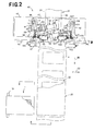
- Fig. 2 is a plan view illustrating a part of process for continuously making the diaper 1
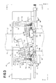
- Fig. 3 is a scale-enlarged plan view illustrating a part of Fig. 2
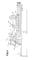
- Fig. 4 is a partially cutaway sectional view taken along the line IV-IV in Fig. 3.
- a first continuous web 21 destined to form the backsheet 3 of the diaper 1 is continuously fed in a machine direction MD downward from above.
- the continuous web 21 is guided through an edge controller 40 to control a width of the web 21 to a desired dimension and then loaded thereon with the cores 4 which are arranged intermittently in the machine direction MD.
- second continuous web 22 destined to form the topsheet 2 of the diaper 1 is continuously fed so as to cover the cores 4 whereupon the first continuous web 21 and the second continuous web 22 are joined together around the respective cores 4 by means of adhesives or a suitable welding technique to form a continuous assembly 26.
- the continuous assembly 26 is cut along lines each extending in a cross direction CD orthogonal to the machine direction MD between each pair of the adjacent cores 4 followed by attaching a pair of the tape fasteners 13 to the first web 21 of each unit assembly cut from the continuous assembly 26.
- the individual diapers 1 as shown by Fig. 1 are obtained.
- the first and second continuous webs 21, 22 as well as the cores 4 are indicated by imaginary lines and, in Fig. 2, the diaper 1 is illustrated as partially broken away.
- the first continuous web 21 has first and second side edges 31, 32 opposed to each other in the cross direction CD and extending parallel to each other in the machine direction MD.
- the edge controller 40 functions as a controlling means for the first continuous web 21. Specifically, the edge controller 40 guides at least one of vicinities of the first side edge 31 and the second side edge 32 to a position predetermined position in the cross direction CD and thereby controls the width of the first continuous web 21 to a desired dimension.
- the edge controller 40 exemplarily illustrated comprises a first edge controller 41 operatively associated with the first side edge 31 and a second edge controller 42 operatively associated with the second side edge 32. These two edge controllers 41, 42 are substantially identical to each other, so the first edge controller 41 will be primarily described with reference to Figs. 2 through 4.
- the term used herein "vicinities of the respective side edges" should be understood to include the respective side edges and the vicinities thereof.
- the first edge controller 41 includes a movable plate 47 adapted to be movable in the cross direction CD relative to a base plate 46 extending across the first continuous web 21.
- the movable plate 47 is provided with an actuator 48 and a swing arm 49.
- a support bar 51 mounted on the base plate 46 downstream in the machine direction MD and extending in the cross direction CD is provided with a photoelectric sensor unit 52.
- the photoelectric sensor unit 52 electrically connected with the actuator 48 functions to detect an actual position of the first side edge of the first continuous web 21 and to compare this actual position to a predetermined position on which the first side edge 31 should fall. Based on such comparison, the photoelectric sensor unit 52 calculates a direction and a distance in and by which the first side edge 31 should be shifted to the predetermined position.
- the actuator 48 comprising a servomotor 53, a extensible/retractable arm 54 and a ball screw joint (not shown) interposed between these motor 53 and the arm 54 rotates the motor 53 in accordance with the direction and the distance calculated by the photoelectric sensor unit 52 and thereby and thereby extends or retracts the arm 54 depending on a result of calculation.
- a distal end of the extensible/retractable arm 54 is rotatably connected to a distal end 59 of the swing arm 49 by means of a pivot pin 56.
- a proximal end 57 of the swing arm 49 opposite to the distal end 59 is mounted on the movable plate 47 by means of a pivot pin 58 around which the swing arm 49 can swing in- and outward in the cross direction CD.
- the distal end 59 of the swing arm 49 is provided with a roll unit 63 specifically comprising first and second nip rolls 61, 62 arranged vertically as viewed in Fig. 4.
- the roll unit 63 comprises a bracket 64 fixed to the swing arm 49, a supporter 67 extending from this bracket 64 and supporting a first rotary shaft 66 at its opposite ends and a second rotary shaft 68 extending from the bracket 64 and supporting the second nip roll 62 at its opposite ends.
- the first nip roll 61 and the second nip roll 62 are free to rotate about the first rotary shaft 66 and the second rotary shaft 68, respectively, both in the machine direction MD and in the direction opposite to the machine direction MD.
- the photoelectric sensor unit 52 shown in Fig. 4 has an upper arm 82 provided with a light emitter 82a extending in the cross section CD and a lower arm 83 provided with a light receiver 83a extending in the cross section CD. From the light receiver 83a, an output cord 83b extends toward the actuator 48.
- the unit 52 is adapted to detect the first side edge 31 of the first continuous web 21 indicated by imaginary line.
- a photoelectric sensor unit 152 in the second edge controller 42 of the edge controller 40 is shown as mounted on a support bar 151, but this photoelectric sensor unit 152 is not shown in Fig. 4.
- an actual position of the first side edge 31 detected by the photoelectric sensor unit 52 located downstream of the first edge controller 41 is compared with the predetermined position on which the first side edge 31 should fall.
- Operation of the actuator 48 based on such comparison causes the swing arm 49 connected with the extensible/retractable arm 54 to swing about the pivot pin 58 by a desired angle inward or outward in the cross direction CD, i.e., inward or outward in the transverse direction of the first continuous web 21.
- the roll unit 63 mounted on the distal end 59 of the swing arm 49 also swings as the swing arm 49 swings in this manner.
- the first rotary shaft 66 of the first nip roll 61 and the second rotary shaft 68 of the second nip roll 62 extend between the machine direction MD and the cross direction CD and normally extend so as to intersect the machine direction MD.
- the first nip roll 61 extending in the transverse direction of the first continuous web 21 after having slightly swung from the cross direction CD toward the machine direction MD is indicated by solid line while the first nip roll 61 having significantly swung outward in the transverse direction of the first continuous web 21 is indicated by imaginary line.
- the second nip roll 62 underlies the first nip roll 61 and therefore can not be seen in Figs. 2 and 3.
- the roll unit 63 functions to move the first side edge 31 and its vicinity of the first continuous web 21 nipped between the first and second nip rolls 61, 62 outward in the transverse direction as the swing arm 49 swings outward in the transverse direction of the first continuous web 21.
- the first and second nip rolls 61, 62 substantially falling on the cross direction as viewed in Figs. 2 and 3 swing so that their respective inner ends 61a, 62a put aside inward in the transverse direction of the first continuous web 21 move to downstream of their respective outer ends 61b, 62b put aside outward in the transverse direction of the first continuous web 21 as viewed in the machine direction MD.
- swing of the arm 49 outward in the transverse direction of the first continuous web 21 causes the rotary shafts 66, 68 of the first and second nip rolls 61, 62 to swing so that a tilt angle ⁇ of these rotary shafts 66, 68 relative to the machine direction MD gradually decreases.
- the movable plate 47 on which the first edge controller 41 is mounted is fixed at a position in the cross direction CD adjusted so that the first and second nip rolls 61, 62 can repetitively swing at any given time in the vicinity of the first side edge 31 of the first continuous web 21.
- the second edge controller 42 constituting the edge controller 40 comprises a movable plate 147 mounted on the base plate 46 so that its position in the cross direction CD may be adjusted, an actuator 148, a swing arm 149, a pivot pin 148, a roll unit 163 and a photoelectric sensor unit 152.
- those added with 100 designate the components constituting the second edge controller 42.
- the roll unit 163 is placed in a mirror symmetric relationship with the roll unit 63 in the first edge controller 41 and the other components such as the actuator 148 and the swing arm 149 are mounted on the movable plate 147 in an appropriate layout allowing such mirror symmetric relationship between these roll units 63. 163.
- the arm 149 adapted to in- and outward swing on the basis of data supplied from the photoelectric sensor unit 152 adapted to detect an actual position of the second side edge 32.
- the first and second nip rolls 161, 162 of the roll unit 163 swing in the same manner as in the case of the first and second nip rolls 61, 62 of the roll unit 63 so that so that their respective inner ends 161a, 162a put aside inward in the transverse direction of the first continuous web 21 move to downstream of their respective outer ends 161b, 162b put aside outward in the transverse direction of the first continuous web 21 as viewed in the machine direction MD with a tilt angle ⁇ of these nip rolls 161b, 162b relative to the machine direction MD gradually decreasing.
- the first and second edge controllers 41, 42 operate independently of each other.
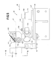
- Fig. 5 is a sectional view taken along the line V-V in Fig. 3, showing profiles of the second edge controller 42 and the photoelectric sensor unit 152.
- the roll unit 163 is oriented in coincidence with the cross direction CD.
- the pivot pin 158 of the swing arm 149 lies upstream in the machine direction MD and rotatably mounted on a pedestal 171 which is, in turn, fixed to the movable plate 147.
- the swing arm 149 extends from upstream toward downstream in the machine direction MD and provided on its distal end 159 with the roll unit 163 fixed thereto.
- the extensible/retractable arm 154 is mounted on the swing arm 149 by means of the pivot pin 156 so that the arm 154 can rotate around the pivot pin 156.
- the roll unit 163 comprises the first nip roll 161 and the second nip roll 162. After having been nipped by these two rolls 161, 162, the first continuous web 21 horizontally runs through the photoelectric sensor unit 152 and further runs toward downstream in the machine direction MD as indicated by imaginary line.
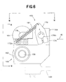
- Fig. 6 is a scale-enlarged view showing the roll unit 163 Fig. 5
- Fig. 7 is a sectional view taken along the line VII-VII
- Fig. 8 is a sectional view taken along the line VIII-VIII in Fig. 5, respectively.
- the roll unit 163 has a bracket 164 fixed to the swing arm 149.
- the bracket 164 has inner and outer surfaces 173, 174 placed aside inward and outward, respectively as viewed in the transverse direction of the first continuous web 21.
- a cylindrical arm 176 horizontally extends and supports the first nip roll 161 and this arm 176 is provided on its inner end 176a with an inverted square U-shaped supporter 167 mounted thereon by means of coupling means 177 as will be seen in Fig. 8.
- the supporter 167 rotatably supports opposite ends of a first rotary shaft 166 of the first nip roll 161.
- a second rotary shaft 168 supporting the second nip roll 162 horizontally extends and rotatably mounted on the bracket 164.
- an outer end 176b of the cylindrical arm 176 extends and a plate member 179 is fixed around this outer end 176b.
- One end of a coil spring 181 operatively associated with the nip roll unit is anchored on the plate member 179 and the opposite end of the coil spring 181 is anchored on an angular plate 172a of the bracket 164.
- the bracket 164 swings in- and outward integrally with the swing arm 149 around the pivot pin 158.
- the first nip roll 161 is rotatable about the first rotary shaft 166 toward down- and upstream in the machine direction MD.
- the cylindrical arm 176 is supported by the bracket 164 and rotatable in two directions indicated by a double-headed arrow A (See Fig. 6). While the first nip roll 161 can be brought in contact with or spaced from the second nip roll 162 as the cylindrical arm 176 rotates, the first nip roll 161 is normally biased by the spring 181 to come in contact with the second nip roll 162.
- the first nip roll 161 is also rotatable around the coupling means 177 in the direction indicated by the double-headed arrow B (See Fig. 8) .
- the second nip roll 162 is supported by the bracket 164 by means of the second rotary shaft 168 and rotatable toward downstream as well as toward upstream in the machine direction MD. Swing of the first nip roll 161 in the directions indicated by the double-headed arrows A and B causes the vicinity of the second side edge 32 of the first continuous web 21 nipped between the first nip roll 161 and the second nip roll 162 to be held in close contact with these two rolls 161, 162 and thereby to follow in- and outward swinging of these two rolls 161, 162.
- the first and second nip rolls 61, 62 of the roll unit 63 and the first and second nip rolls 161, 162 of the roll unit 163 tilt at angles of ⁇ and ⁇ relative to the machine direction MD when the roll units 63, 163 respectively nip the vicinity of the first side edge 31 and the vicinity of the second side edge 32 of the first continuous web 21. Consequently, a force tending to broaden a transverse dimension of the first continuous web 21 is exerted on the extent of this web 21 between the first and second side edges 31, 32 thereof. If the first continuous web 21 guided through the edge controller 40 has wrinkles, the force tending to broaden the web 21 functions to unwrinkled the web 21.
- the roll units 63, 163 may be previously swung in the respective directions in which the tilt angles ⁇ and ⁇ are appropriately decreased.
- the directions in which the pair of the first and second nip rolls 61, 62 and the pair of the first and second nip rolls 161, 162 are swung about the pivot pins 58, 158, respectively may be appropriately selected to move the vicinity of the first side edge 31 and the vicinity of the second side edge 32 nipped by these pairs of the nip rolls, respectively, together with these rolls outward as well as inward in the transverse direction of the first continuous web 21.
- the method and the apparatus according to the present invention is primarily in that a swinging direction and a swinging extent (i.e., swinging angle) of the first and second nip roll pairs 61, 62; 161, 162 are linked with the respective positions of the first and second side edges 31, 32 of the first continuous web 21 detected by the photoelectric sensor units 52, 152, respectively.
- the photoelectric sensor units 52, 152 are provided immediately downstream of the respective roll units 63, 163 so that a combined effect of the first and second nip roll pairs 61, 161; 161, 162 swinging in this direction and by this extent may be rapidly fed back to the respective actuators 48, 148 and thereby the first continuous web 21 may be rapidly and accurately controlled. It is also possible to ensure a rapid position-change of the first and second side edges 31, 32 by accelerating the servomotors' rotational velocities and thereby accelerating the swinging velocities of the roll units 63, 163.
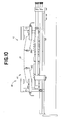
- Fig. 9 is a view similar to Fig. 3, showing one preferred embodiment of the present invention and Fig. 10 is a view similar to Fig. 4, showing this embodiment.
- the edge controller 40 according to this embodiment is distinguished from that shown by Figs. 2 through 4 in that each of the first and second edge controllers 41, 42 comprises a lower roll 262, 362 adapted to come in contact with the lower surface of the first continuous web 21 and not an upper roll adapted to come in contact with the upper surface of the first continuous web 21. While the positions at which the lower rolls 262, 362 are provided are substantially the same as those at which the second nip rolls 62, 162 of Fig. 4 are provided, the first edge controller 41 according to the embodiment shown by Figs.
- a bracket 264 is mounted on a swing arm 249 so that the bracket 264 may swing about the arm 249.
- the lower roll 262 mounted on the bracket 264 extends inward in the transverse direction of the first continuous web 21 so as to describe a rising slope (See Fig. 10) as the bracket 264 appropriately swings.
- the first continuous web 21 is brought into a state as shown by Fig. 10 as these lower rolls 262, 362 are pressed against the vicinities of the first and second side edges 31, 32, respectively.
- these rolls 262, 362 in- and outward swing together with the respective swing arms 249, 349 in the transverse direction of the first continuous web 21 and thereby guide the first and second side edges 31, 32 to the desired positions.
- the positions actually the first and second side edges 31, 32 passing after having been guided by the rolls 262, 362 are detected by photoelectric sensor units 252, 352 and actuators 248, 348 operate in response to data supplied from these sensor units 252, 352 so that the side edges 31, 32 may be guided to the predetermined positions more accurately.
- Slopes at which the lower rolls 262, 362 should tilt may be appropriately adjusted taking account of particular characteristics of the first continuous web 31 such as flexibility, elasticity and slipperiness.
- first and second side edges 31, 32 including the vicinities thereof of the first continuous web 21 are guided by the first and second end controllers 41, 42, respectively, to the desired positions
- the invention may be implemented in a manner that only one of the side edges including the vicinity of this side edge is guided to the desired position.
- an alternative arrangement is also possible in which the first and second nip rolls 61, 62 are shifted from each other in the machine direction MD, i.e., one of the nip rolls is located upstream and the other is located downstream in the machine direction MD.
- Factors such as material, type of surface finish, length and diameter may be appropriately selected depending on the manner in which the first continuous web 21 has been processed and coated with adhesive, if any.
- the roll may be formed from use of materials, for example, sponge rubber obtained from various types of rubber such as urethane rubber and silicone rubber or metallic material.
- the roll may be subjected to a surface treatment such as a satin-like finish to adjust a slipperiness relative to the first continuous web 21.
- Means for position-detection of the first and second side edges 31, 32 is not limited to the photoelectric sensor unit as illustrated and this photoelectric sensor unit may be replaced by the other optical means or physical means. While the present invention has been described with respect to the first continuous web 21 used for the disposable diaper 1, the invention is applicable also to the second continuous web 22 and the other types of continuous web used for articles other than the diaper 1.
- the rotatable rolls used to come in contact with the vicinities of the side edges of the web continuously running in the machine direction and thereby to guide these side edges in the cross direction are adapted to swing in- and outward in the transverse direction of the web wherein the direction and the extend (angle) of swing relative to the machine direction are determined on the basis of the detected positions of the respective side edges of the running web.
- the angle of the rolls relative to the machine direction can be adjustably varied to vary a force tending to broaden the web and at the same time the positions of the side edges of the web can be forcibly and quickly varied by oscillating the rolls. In this way, the side edges of the web can be easily and accurately guided to the predetermined position.
Landscapes
- Health & Medical Sciences (AREA)
- Engineering & Computer Science (AREA)
- Vascular Medicine (AREA)
- Epidemiology (AREA)
- Biomedical Technology (AREA)
- Heart & Thoracic Surgery (AREA)
- Manufacturing & Machinery (AREA)
- Life Sciences & Earth Sciences (AREA)
- Animal Behavior & Ethology (AREA)
- General Health & Medical Sciences (AREA)
- Public Health (AREA)
- Veterinary Medicine (AREA)
- Registering, Tensioning, Guiding Webs, And Rollers Therefor (AREA)
- Treatment Of Fiber Materials (AREA)
Abstract
A roll means comprising a first nip roll (61) rotating
about a shaft (66) extending in a direction defined between a
machine direction (MD) and a cross direction (CD) is put in
contact with a side edge (31) of a web (21) continuously running
in the machine direction (MD). The shaft (66) is mounted on
an arm (49) adapted to rotate back-and-forth so that the shaft
(66) can swing in- and outward in the cross direction (CD).
Downstream of the roll means, the side edge (31) is
position-detected and the arm (49) is made swing by a desired
angle determined on the basis of a difference between the actual
position and a desired position of the side edge (31).
Description
The present invention relates to a method and an apparatus
allowing, in the course of continuously feeding a flexible web
of nonwoven fabric, plastic film, paper or the like in a machine
direction, side edges of such a web to be guided to desired
positions in a cross direction orthogonal to the machine
direction.
It is well known in prior art references 1, 2, 3 listed
below, in the course of continuously feeding a flexible web of
nonwoven fabric, plastic film, paper or the like in a machine
direction, to put guide roll means rotating about respective
shafts each obliquely extending at a desired angle with respect
to the machine direction in contact with the vicinities of side
edges of such a web and thereby to move the side edges so that
the web may be broadened. It is also well known that the web
can be unwrinkled by guiding the side edges of the web. Prior
art reference discloses a method for guiding the side edges of
the web continuously fed to desired positions by operatively
associating such guide roll means with detector means adapted
to detect actual positions of the web.
Of the apparatuses disclosed in Prior art references 1
through 3, one apparatus has the guide roll means fixed at a
predetermined angle relative to the machine direction, another
apparatus is adapted to vary a contact pressure between the
guide roll means and the web, and further another apparatus has
the guide roll means in the form of paired nip rolls adapted
to vary a nip pressure against the web. When it is intended
to guide the side edges of the web detected to be out of
coincidence with desired positions to these desired positions
by appropriately varying the contact pressure or the nip
pressure, it is relatively easy to shift the side edges outward
in the axial direction of the guide roll means, i.e., outward
in the cross direction corresponding to the transverse
direction of the web. However, it is difficult to shift the
side edges in the directions other than the outward direction,
for example, inward in the cross direction. For these
apparatuses disclosed in Prior art references 1, 2, 3
respectively provided with such guide roll means, it has been
impossible to guide the side edges of the web little by little
with a high accuracy or to position-shift the side edges of the
web quickly. In addition, the web of nonwoven fabric, plastic
film or the like which has been tightly wounded around a roll
core generally exhibits a subtle variation in a width of the
web as the web is released and fed in the machine direction
directly from such tightly wound state. Such subtle variation
of the width of the web may occur also due to a pulling force
exerted on the web in the machine direction. Synergistic effect
of these variation destabilizes the width of the web and
therefore destabilizes positions of the side edges of the web
in the cross direction. In consequence, it is difficult to
continuously make articles each having a high dimensional
accuracy by utilizing the side edges of the web.
It is an object of the present invention to provide a
method and an apparatus facilitating the side edges of the web
continuously running in the machine direction to be quickly
guided to desired positions in the cross direction when these
side edges are detected to be out of coincidence with the desired
positions in the cross direction.
According to a first aspect of the present invention,
there is provided a method for guiding a web continuously
running in a machine direction and having a pair of side edges
opposed to each other in a cross direction orthogonal to the
machine direction so that at least one of the side edges is guided
to a predetermined position in the cross direction by putting
roll means rotating about a shaft extending in a direction
defined between the machine direction and the cross direction
in contact with a vicinity of at least one of the side edges.
The first aspect of the present invention comprises the
steps of: mounting an arm having a proximal end and a distal
end opposed to the proximal end at the proximal end on a pivot
pin adapted to rotate back-and-forth so that the arm swings
about the pivot pin in- and outward as viewed in the cross
direction, supporting the shaft of the roll means by the distal
end of the arm so that the roll means also swing about the pivot
pin in- and outward, detecting, at downstream of the roll means,
a position of the one side edge immediately after this side edge
has been guided, and driving the arm by driving means adapted
to operate on the basis of a difference between the position
detected in this manner and the predetermined position so that
the arm swings in- or outward in the cross direction by a
predetermined angle.
The present invention on the first aspect may be
implemented also in manners as follow:
According to a second aspect of the present invention,
there is provided an apparatus for guiding a web continuously
running in a machine direction and having a pair of side edges
opposed to each other in a cross direction orthogonal to the
machine direction so that at least one of the side edges is guided
to a predetermined position in the cross direction by putting
roll means rotating about a shaft extending in a direction
defined between the machine direction and the cross direction
in contact with a vicinity of at least one of the side edges.
The second aspect of the present invention further
comprises the following features: the shaft of the roll means
is supported on a distal end of an arm having a proximal end
and the distal end opposed to the proximal end; the proximal
end of the arm is mounted on a pivot pin adapted to rotate
back-and-forth so that the arm swings about the pivot pin in-
and outward as viewed in the cross direction; detector means
is provided downstream of the roll means in the machine
direction to detect a position of the one side edge after this
side edge has been guided; and the arm is operatively associated
with driving means adapted to operate on the basis of a
difference between the position detected by the detector means
and the predetermined position so that the arm swings in- or
outward in the cross direction by a predetermined angle.
The second aspect of the present invention may be
implemented also in manners as follow:
Details of a method and an apparatus according to the
present invention will be more fully understood from the
description given hereunder with reference to the accompanying
drawings.
A disposable diaper 1 shown by Fig. 1 in a plan view as
partially broken away is a product obtained by a method and an
apparatus according to the present invention. This diaper 1
comprises a liquid-pervious topsheet 2, a liquid-impervious
backsheet 3 and a liquid-absorbent core 4 interposed between
these sheets 2, 3. The diaper 1 has a in- and outward direction
(longitudinal direction as viewed in Fig. 1) and a
waist-surrounding direction (transverse direction as viewed in
Fig. 1). The diaper 1 is peripherally contoured by a pair of
side edges 11 extending parallel to each other in the in- and
outward direction and a pair of ends extending parallel to each
other in the waist-surrounding direction. As viewed in the in-
and outward direction, the diaper 1 is composed of a front waist
region 6, a rear waist region 7 and a crotch region 8 extending
between these waist regions 6, 7 wherein tape fasteners 13
laterally extend from the side edges 11 in the rear waist region
7. The topsheet 2 may be formed from liquid-pervious materials
such as nonwoven fabrics or aperture plastic films, the
backsheet 3 may be formed from liquid-impervious materials
selected from plastic films, nonwoven fabrics and plastic
film/nonwoven fabric laminates. The diaper 1 further
comprises elastic members attached in a stretched state thereto
so as to extend along the side edges 11 and the ends 12.
Fig. 2 is a plan view illustrating a part of process for
continuously making the diaper 1, Fig. 3 is a scale-enlarged
plan view illustrating a part of Fig. 2 and Fig. 4 is a partially
cutaway sectional view taken along the line IV-IV in Fig. 3.
As viewed in Fig. 2, a first continuous web 21 destined to form
the backsheet 3 of the diaper 1 is continuously fed in a machine
direction MD downward from above. The continuous web 21 is
guided through an edge controller 40 to control a width of the
web 21 to a desired dimension and then loaded thereon with the
cores 4 which are arranged intermittently in the machine
direction MD. Then, second continuous web 22 destined to form
the topsheet 2 of the diaper 1 is continuously fed so as to cover
the cores 4 whereupon the first continuous web 21 and the second
continuous web 22 are joined together around the respective
cores 4 by means of adhesives or a suitable welding technique
to form a continuous assembly 26. The continuous assembly 26
is cut along lines each extending in a cross direction CD
orthogonal to the machine direction MD between each pair of the
adjacent cores 4 followed by attaching a pair of the tape
fasteners 13 to the first web 21 of each unit assembly cut from
the continuous assembly 26. In this manner, the individual
diapers 1 as shown by Fig. 1 are obtained. In Figs. 2, 3 and
4, the first and second continuous webs 21, 22 as well as the
cores 4 are indicated by imaginary lines and, in Fig. 2, the
diaper 1 is illustrated as partially broken away.
The first continuous web 21 has first and second side
edges 31, 32 opposed to each other in the cross direction CD
and extending parallel to each other in the machine direction
MD. The edge controller 40 functions as a controlling means
for the first continuous web 21. Specifically, the edge
controller 40 guides at least one of vicinities of the first
side edge 31 and the second side edge 32 to a position
predetermined position in the cross direction CD and thereby
controls the width of the first continuous web 21 to a desired
dimension. The edge controller 40 exemplarily illustrated
comprises a first edge controller 41 operatively associated
with the first side edge 31 and a second edge controller 42
operatively associated with the second side edge 32. These two
edge controllers 41, 42 are substantially identical to each
other, so the first edge controller 41 will be primarily
described with reference to Figs. 2 through 4. The term used
herein "vicinities of the respective side edges" should be
understood to include the respective side edges and the
vicinities thereof.
The first edge controller 41 includes a movable plate 47
adapted to be movable in the cross direction CD relative to a
base plate 46 extending across the first continuous web 21. The
movable plate 47 is provided with an actuator 48 and a swing
arm 49. A support bar 51 mounted on the base plate 46 downstream
in the machine direction MD and extending in the cross direction
CD is provided with a photoelectric sensor unit 52. The
photoelectric sensor unit 52 electrically connected with the
actuator 48 functions to detect an actual position of the first
side edge of the first continuous web 21 and to compare this
actual position to a predetermined position on which the first
side edge 31 should fall. Based on such comparison, the
photoelectric sensor unit 52 calculates a direction and a
distance in and by which the first side edge 31 should be shifted
to the predetermined position. The actuator 48 comprising a
servomotor 53, a extensible/retractable arm 54 and a ball screw
joint (not shown) interposed between these motor 53 and the arm
54 rotates the motor 53 in accordance with the direction and
the distance calculated by the photoelectric sensor unit 52 and
thereby and thereby extends or retracts the arm 54 depending
on a result of calculation. A distal end of the
extensible/retractable arm 54 is rotatably connected to a
distal end 59 of the swing arm 49 by means of a pivot pin 56.
A proximal end 57 of the swing arm 49 opposite to the distal
end 59 is mounted on the movable plate 47 by means of a pivot
pin 58 around which the swing arm 49 can swing in- and outward
in the cross direction CD. The distal end 59 of the swing arm
49 is provided with a roll unit 63 specifically comprising first
and second nip rolls 61, 62 arranged vertically as viewed in
Fig. 4. The roll unit 63 comprises a bracket 64 fixed to the
swing arm 49, a supporter 67 extending from this bracket 64 and
supporting a first rotary shaft 66 at its opposite ends and a
second rotary shaft 68 extending from the bracket 64 and
supporting the second nip roll 62 at its opposite ends. The
first nip roll 61 and the second nip roll 62 are free to rotate
about the first rotary shaft 66 and the second rotary shaft 68,
respectively, both in the machine direction MD and in the
direction opposite to the machine direction MD.
The photoelectric sensor unit 52 shown in Fig. 4 has an
upper arm 82 provided with a light emitter 82a extending in the
cross section CD and a lower arm 83 provided with a light receiver
83a extending in the cross section CD. From the light receiver
83a, an output cord 83b extends toward the actuator 48. The
unit 52 is adapted to detect the first side edge 31 of the first
continuous web 21 indicated by imaginary line. In Figs. 2 and
3, a photoelectric sensor unit 152 in the second edge controller
42 of the edge controller 40 is shown as mounted on a support
bar 151, but this photoelectric sensor unit 152 is not shown
in Fig. 4.
With the edge controller 40 constructed in this manner,
an actual position of the first side edge 31 detected by the
photoelectric sensor unit 52 located downstream of the first
edge controller 41 is compared with the predetermined position
on which the first side edge 31 should fall. Operation of the
actuator 48 based on such comparison causes the swing arm 49
connected with the extensible/retractable arm 54 to swing about
the pivot pin 58 by a desired angle inward or outward in the
cross direction CD, i.e., inward or outward in the transverse
direction of the first continuous web 21. The roll unit 63
mounted on the distal end 59 of the swing arm 49 also swings
as the swing arm 49 swings in this manner.
In the roll unit 63, the first rotary shaft 66 of the first
nip roll 61 and the second rotary shaft 68 of the second nip
roll 62 extend between the machine direction MD and the cross
direction CD and normally extend so as to intersect the machine
direction MD. In Figs. 2 and 3, the first nip roll 61 extending
in the transverse direction of the first continuous web 21 after
having slightly swung from the cross direction CD toward the
machine direction MD is indicated by solid line while the first
nip roll 61 having significantly swung outward in the transverse
direction of the first continuous web 21 is indicated by
imaginary line. The second nip roll 62 underlies the first nip
roll 61 and therefore can not be seen in Figs. 2 and 3. The
roll unit 63 functions to move the first side edge 31 and its
vicinity of the first continuous web 21 nipped between the first
and second nip rolls 61, 62 outward in the transverse direction
as the swing arm 49 swings outward in the transverse direction
of the first continuous web 21. In this course, the first and
second nip rolls 61, 62 substantially falling on the cross
direction as viewed in Figs. 2 and 3 swing so that their
respective inner ends 61a, 62a put aside inward in the
transverse direction of the first continuous web 21 move to
downstream of their respective outer ends 61b, 62b put aside
outward in the transverse direction of the first continuous web
21 as viewed in the machine direction MD. In other words, swing
of the arm 49 outward in the transverse direction of the first
continuous web 21 causes the rotary shafts 66, 68 of the first
and second nip rolls 61, 62 to swing so that a tilt angle α
of these rotary shafts 66, 68 relative to the machine direction
MD gradually decreases. The movable plate 47 on which the first
edge controller 41 is mounted is fixed at a position in the cross
direction CD adjusted so that the first and second nip rolls
61, 62 can repetitively swing at any given time in the vicinity
of the first side edge 31 of the first continuous web 21.
Similar to the first edge controller 41, the second edge
controller 42 constituting the edge controller 40 comprises a
movable plate 147 mounted on the base plate 46 so that its
position in the cross direction CD may be adjusted, an actuator
148, a swing arm 149, a pivot pin 148, a roll unit 163 and a
photoelectric sensor unit 152. Of these reference numerals,
those added with 100 designate the components constituting the
second edge controller 42. In the second edge controller 42,
the roll unit 163 is placed in a mirror symmetric relationship
with the roll unit 63 in the first edge controller 41 and the
other components such as the actuator 148 and the swing arm 149
are mounted on the movable plate 147 in an appropriate layout
allowing such mirror symmetric relationship between these roll
units 63. 163. The arm 149 adapted to in- and outward swing
on the basis of data supplied from the photoelectric sensor unit
152 adapted to detect an actual position of the second side edge
32. In response to swing of this arm 149 outward in the
transverse direction of the first continuous web 21, the first
and second nip rolls 161, 162 of the roll unit 163 swing in the
same manner as in the case of the first and second nip rolls
61, 62 of the roll unit 63 so that so that their respective inner
ends 161a, 162a put aside inward in the transverse direction
of the first continuous web 21 move to downstream of their
respective outer ends 161b, 162b put aside outward in the
transverse direction of the first continuous web 21 as viewed
in the machine direction MD with a tilt angle β of these nip
rolls 161b, 162b relative to the machine direction MD gradually
decreasing. The first and second edge controllers 41, 42
operate independently of each other.
Fig. 5 is a sectional view taken along the line V-V in
Fig. 3, showing profiles of the second edge controller 42 and
the photoelectric sensor unit 152. In Fig. 5, the roll unit
163 is oriented in coincidence with the cross direction CD. In
the second edge controller 42, the pivot pin 158 of the swing
arm 149 lies upstream in the machine direction MD and rotatably
mounted on a pedestal 171 which is, in turn, fixed to the movable
plate 147. The swing arm 149 extends from upstream toward
downstream in the machine direction MD and provided on its
distal end 159 with the roll unit 163 fixed thereto. In the
vicinity of the distal end 159, the extensible/retractable arm
154 is mounted on the swing arm 149 by means of the pivot pin
156 so that the arm 154 can rotate around the pivot pin 156.
The roll unit 163 comprises the first nip roll 161 and the second
nip roll 162. After having been nipped by these two rolls 161,
162, the first continuous web 21 horizontally runs through the
photoelectric sensor unit 152 and further runs toward
downstream in the machine direction MD as indicated by imaginary
line.
Fig. 6 is a scale-enlarged view showing the roll unit 163
Fig. 5, Fig. 7 is a sectional view taken along the line VII-VII,
and Fig. 8 is a sectional view taken along the line VIII-VIII
in Fig. 5, respectively. The roll unit 163 has a bracket 164
fixed to the swing arm 149. The bracket 164 has inner and outer
surfaces 173, 174 placed aside inward and outward, respectively
as viewed in the transverse direction of the first continuous
web 21. From the inner surface 173, a cylindrical arm 176
horizontally extends and supports the first nip roll 161 and
this arm 176 is provided on its inner end 176a with an inverted
square U-shaped supporter 167 mounted thereon by means of
coupling means 177 as will be seen in Fig. 8. The supporter
167 rotatably supports opposite ends of a first rotary shaft
166 of the first nip roll 161. Also from the inner surface 173,
a second rotary shaft 168 supporting the second nip roll 162
horizontally extends and rotatably mounted on the bracket 164.
From the outer surface 174 of the bracket 164, an outer end 176b
of the cylindrical arm 176 extends and a plate member 179 is
fixed around this outer end 176b. One end of a coil spring 181
operatively associated with the nip roll unit is anchored on
the plate member 179 and the opposite end of the coil spring
181 is anchored on an angular plate 172a of the bracket 164.
In the roll unit 163 constructed in this manner, the
bracket 164 swings in- and outward integrally with the swing
arm 149 around the pivot pin 158. The first nip roll 161 is
rotatable about the first rotary shaft 166 toward down- and
upstream in the machine direction MD. The cylindrical arm 176
is supported by the bracket 164 and rotatable in two directions
indicated by a double-headed arrow A (See Fig. 6). While the
first nip roll 161 can be brought in contact with or spaced from
the second nip roll 162 as the cylindrical arm 176 rotates, the
first nip roll 161 is normally biased by the spring 181 to come
in contact with the second nip roll 162. The first nip roll
161 is also rotatable around the coupling means 177 in the
direction indicated by the double-headed arrow B (See Fig. 8) .
The second nip roll 162 is supported by the bracket 164 by means
of the second rotary shaft 168 and rotatable toward downstream
as well as toward upstream in the machine direction MD. Swing
of the first nip roll 161 in the directions indicated by the
double-headed arrows A and B causes the vicinity of the second
side edge 32 of the first continuous web 21 nipped between the
first nip roll 161 and the second nip roll 162 to be held in
close contact with these two rolls 161, 162 and thereby to follow
in- and outward swinging of these two rolls 161, 162.
The first and second nip rolls 61, 62 of the roll unit
63 and the first and second nip rolls 161, 162 of the roll unit
163 tilt at angles of α and β relative to the machine direction
MD when the roll units 63, 163 respectively nip the vicinity
of the first side edge 31 and the vicinity of the second side
edge 32 of the first continuous web 21. Consequently, a force
tending to broaden a transverse dimension of the first
continuous web 21 is exerted on the extent of this web 21 between
the first and second side edges 31, 32 thereof. If the first
continuous web 21 guided through the edge controller 40 has
wrinkles, the force tending to broaden the web 21 functions to
unwrinkled the web 21. When such effect is not required, the
roll units 63, 163 may be previously swung in the respective
directions in which the tilt angles α and β are appropriately
decreased. The directions in which the pair of the first and
second nip rolls 61, 62 and the pair of the first and second
nip rolls 161, 162 are swung about the pivot pins 58, 158,
respectively may be appropriately selected to move the vicinity
of the first side edge 31 and the vicinity of the second side
edge 32 nipped by these pairs of the nip rolls, respectively,
together with these rolls outward as well as inward in the
transverse direction of the first continuous web 21.
As will be understood from the aforementioned description,
the method and the apparatus according to the present invention
is primarily in that a swinging direction and a swinging extent
(i.e., swinging angle) of the first and second nip roll pairs
61, 62; 161, 162 are linked with the respective positions of
the first and second side edges 31, 32 of the first continuous
web 21 detected by the photoelectric sensor units 52, 152,
respectively. More specifically, the photoelectric sensor
units 52, 152 are provided immediately downstream of the
respective roll units 63, 163 so that a combined effect of the
first and second nip roll pairs 61, 161; 161, 162 swinging in
this direction and by this extent may be rapidly fed back to
the respective actuators 48, 148 and thereby the first
continuous web 21 may be rapidly and accurately controlled. It
is also possible to ensure a rapid position-change of the first
and second side edges 31, 32 by accelerating the servomotors'
rotational velocities and thereby accelerating the swinging
velocities of the roll units 63, 163.
Fig. 9 is a view similar to Fig. 3, showing one preferred
embodiment of the present invention and Fig. 10 is a view similar
to Fig. 4, showing this embodiment. The edge controller 40
according to this embodiment is distinguished from that shown
by Figs. 2 through 4 in that each of the first and second edge
controllers 41, 42 comprises a lower roll 262, 362 adapted to
come in contact with the lower surface of the first continuous
web 21 and not an upper roll adapted to come in contact with
the upper surface of the first continuous web 21. While the
positions at which the lower rolls 262, 362 are provided are
substantially the same as those at which the second nip rolls
62, 162 of Fig. 4 are provided, the first edge controller 41
according to the embodiment shown by Figs. 9 and 10 is
distinguished from the previous embodiment shown by Fig. 4 in
that a bracket 264 is mounted on a swing arm 249 so that the
bracket 264 may swing about the arm 249. The lower roll 262
mounted on the bracket 264 extends inward in the transverse
direction of the first continuous web 21 so as to describe a
rising slope (See Fig. 10) as the bracket 264 appropriately
swings. This is true for the lower roll 362 of the second edge
controller 42. The first continuous web 21 is brought into a
state as shown by Fig. 10 as these lower rolls 262, 362 are
pressed against the vicinities of the first and second side
edges 31, 32, respectively. Then, these rolls 262, 362 in- and
outward swing together with the respective swing arms 249, 349
in the transverse direction of the first continuous web 21 and
thereby guide the first and second side edges 31, 32 to the
desired positions.. According to this embodiment also, the
positions actually the first and second side edges 31, 32
passing after having been guided by the rolls 262, 362 are
detected by photoelectric sensor units 252, 352 and actuators
248, 348 operate in response to data supplied from these sensor
units 252, 352 so that the side edges 31, 32 may be guided to
the predetermined positions more accurately. Slopes at which
the lower rolls 262, 362 should tilt may be appropriately
adjusted taking account of particular characteristics of the
first continuous web 31 such as flexibility, elasticity and
slipperiness.
While the invention has been described hereinabove on the
basis of the embodiments in which the first and second side edges
31, 32 including the vicinities thereof of the first continuous
web 21 are guided by the first and second end controllers 41,
42, respectively, to the desired positions, the invention may
be implemented in a manner that only one of the side edges
including the vicinity of this side edge is guided to the desired
position. Without departing from the scope of the invention,
an alternative arrangement is also possible in which the first
and second nip rolls 61, 62 are shifted from each other in the
machine direction MD, i.e., one of the nip rolls is located
upstream and the other is located downstream in the machine
direction MD. Factors such as material, type of surface finish,
length and diameter may be appropriately selected depending on
the manner in which the first continuous web 21 has been
processed and coated with adhesive, if any. The roll may be
formed from use of materials, for example, sponge rubber
obtained from various types of rubber such as urethane rubber
and silicone rubber or metallic material. The roll may be
subjected to a surface treatment such as a satin-like finish
to adjust a slipperiness relative to the first continuous web
21. Means for position-detection of the first and second side
edges 31, 32 is not limited to the photoelectric sensor unit
as illustrated and this photoelectric sensor unit may be
replaced by the other optical means or physical means. While
the present invention has been described with respect to the
first continuous web 21 used for the disposable diaper 1, the
invention is applicable also to the second continuous web 22
and the other types of continuous web used for articles other
than the diaper 1.
According to the present invention, the rotatable rolls
used to come in contact with the vicinities of the side edges
of the web continuously running in the machine direction and
thereby to guide these side edges in the cross direction are
adapted to swing in- and outward in the transverse direction
of the web wherein the direction and the extend (angle) of swing
relative to the machine direction are determined on the basis
of the detected positions of the respective side edges of the
running web. According to the present invention, the angle of
the rolls relative to the machine direction can be adjustably
varied to vary a force tending to broaden the web and at the
same time the positions of the side edges of the web can be
forcibly and quickly varied by oscillating the rolls. In this
way, the side edges of the web can be easily and accurately guided
to the predetermined position.
Claims (10)
- A method for guiding a web continuously running in a machine direction and having a pair of side edges opposed to each other in a cross direction orthogonal to said machine direction so that at least one of said side edges is guided to a predetermined position in said cross direction by putting roll means rotating about a shaft extending in a direction defined between said machine direction and said cross direction in contact with a vicinity of at least one of said side edges, said method comprising the steps of:mounting an arm having a proximal end and a distal end opposed to said proximal end at said proximal end on a pivot pin adapted to rotate back-and-forth so that said arm swings around said pivot pin in- and outward as viewed in said cross direction;supporting said shaft of said roll means by said distal end of said arm so that said roll means also swing about said pivot pin in- and outward;detecting, at downstream of said roll means, a position of said one side edge after this side edge has been guided; anddriving said arm by driving means adapted to operate on the basis of a difference between said position detected in this manner and said desired position so that said arm swings in- or outward in said cross direction by a predetermined angle.
- The method according to Claim 1, wherein said driving means comprises an extensible/retractable arm operatively associated with a servomotor adapted to rotate in a direction and at a rotational frequency depending on the difference between said detected position and said desired position and thereby to extend or retract said extensible/retractable arm so that said side edge is guided to said desired position.
- The method according to Claim 1 or 2, wherein said roll means is put in contact with at least one side of said web.
- The method according to Claim 1 or 2, wherein said roll means comprises a pair of rolls extending in parallel to each other and adapted to nip at least said one side edge and the vicinity thereof.
- The method according to any one of Claims 1, 2, 3 and 4, wherein said roll means are provided in vicinities of a pair of said side edges to guide these side edges to respective said desired positions.
- An apparatus for guiding a web continuously running in a machine direction and having a pair of side edges opposed to each other in a cross direction orthogonal to said machine direction so that at least one of said side edges is guided to a predetermined position in said cross direction by putting roll means rotating about a shaft extending in a direction defined between said machine direction and said cross direction in contact with a vicinity of at least one of said side edges, said apparatus further comprising:said shaft of said roll means being supported on a distal end of an arm which has a proximal end and said distal end opposed to said proximal end;said proximal end of said arm being mounted on a pivot pin adapted to rotate back-and-forth so that said arm swings about said pivot pin in- and outward as viewed in said cross direction;detector means being provided downstream of said roll means in said machine direction to detect a position of said one side edge immediately after said one side edge has been guided; andsaid arm being operatively associated with driving means adapted to operate on the basis of a difference between said position detected by said detector means and said desired position so that said arm swing in- or outward in said cross direction by a desired angle.
- The apparatus according to Claim 6, wherein said driving means comprises an extensible/retractable arm operatively associated with a servomotor.
- The apparatus according to Claim 6 or 7, wherein said roll means is put in contact with at least one side of said web.
- The apparatus according to Claim 6 or 7, wherein said roll means comprises a pair of rolls extending in parallel to each other and adapted to nip at least said one side edge and the vicinity thereof.
- The apparatus according to any one of Claims 6, 7, 8 and 9, wherein said roll means are provided in vicinities of a pair of said side edges to guide these side edges to respective said predetermined positions.
Applications Claiming Priority (3)
| Application Number | Priority Date | Filing Date | Title |
|---|---|---|---|
| JP2003005961 | 2003-01-14 | ||
| JP2003005961A JP4503929B2 (en) | 2003-01-14 | 2003-01-14 | Method for guiding side edges of continuously running web and apparatus therefor |
| PCT/JP2004/000180 WO2004063069A1 (en) | 2003-01-14 | 2004-01-14 | Method and device for guiding side edge of continuously running web |
Publications (1)
| Publication Number | Publication Date |
|---|---|
| EP1595835A1 true EP1595835A1 (en) | 2005-11-16 |
Family
ID=32709037
Family Applications (1)
| Application Number | Title | Priority Date | Filing Date |
|---|---|---|---|
| EP04702065A Withdrawn EP1595835A1 (en) | 2003-01-14 | 2004-01-14 | Method and apparatus for guiding side edges of continuously running web |
Country Status (5)
| Country | Link |
|---|---|
| US (1) | US20050056678A1 (en) |
| EP (1) | EP1595835A1 (en) |
| JP (1) | JP4503929B2 (en) |
| TW (1) | TW200415101A (en) |
| WO (1) | WO2004063069A1 (en) |
Cited By (1)
| Publication number | Priority date | Publication date | Assignee | Title |
|---|---|---|---|---|
| CN101795949B (en) * | 2007-08-29 | 2013-12-25 | Sca卫生用品公司 | Device and method for controlling web |
Families Citing this family (27)
| Publication number | Priority date | Publication date | Assignee | Title |
|---|---|---|---|---|
| US10456302B2 (en) | 2006-05-18 | 2019-10-29 | Curt G. Joa, Inc. | Methods and apparatus for application of nested zero waste ear to traveling web |
| US9433538B2 (en) | 2006-05-18 | 2016-09-06 | Curt G. Joa, Inc. | Methods and apparatus for application of nested zero waste ear to traveling web and formation of articles using a dual cut slip unit |
| US9550306B2 (en) | 2007-02-21 | 2017-01-24 | Curt G. Joa, Inc. | Single transfer insert placement and apparatus with cross-direction insert placement control |
| US9944487B2 (en) | 2007-02-21 | 2018-04-17 | Curt G. Joa, Inc. | Single transfer insert placement method and apparatus |
| JP5363015B2 (en) | 2007-03-28 | 2013-12-11 | 花王株式会社 | Method for manufacturing worn article |
| JP2008285267A (en) * | 2007-05-16 | 2008-11-27 | Sanjo Machine Works Ltd | Web working device |
| US20090211070A1 (en) * | 2008-02-26 | 2009-08-27 | Uwe Schneider | Apparatus And Method For Centering And Spreading A Web |
| JP2010227546A (en) * | 2009-03-02 | 2010-10-14 | Uni Charm Corp | Conveyor, and method of manufacturing absorbent article |
| TWI446974B (en) | 2009-06-30 | 2014-08-01 | 東麗工程股份有限公司 | And a conveyor device for coating the substrate on both sides |
| US9089453B2 (en) | 2009-12-30 | 2015-07-28 | Curt G. Joa, Inc. | Method for producing absorbent article with stretch film side panel and application of intermittent discrete components of an absorbent article |
| CN102152988B (en) * | 2011-01-06 | 2013-09-04 | 广州毅昌科技股份有限公司 | Film tension device |
| US20130063587A1 (en) * | 2011-03-09 | 2013-03-14 | Curt G. Joa, Inc. | Apparatus and method for minimizing waste and improving quality and production in web processing operations by automatic narrow web twist defect correction |
| ES2561754T3 (en) | 2012-02-20 | 2016-02-29 | Curt G. Joa, Inc. | Method for forming joints between discrete components of disposable items |
| US9809414B2 (en) | 2012-04-24 | 2017-11-07 | Curt G. Joa, Inc. | Elastic break brake apparatus and method for minimizing broken elastic rethreading |
| JP5859918B2 (en) | 2012-05-31 | 2016-02-16 | ユニ・チャーム株式会社 | Absorbent article manufacturing apparatus and absorbent article manufacturing method |
| US9283683B2 (en) | 2013-07-24 | 2016-03-15 | Curt G. Joa, Inc. | Ventilated vacuum commutation structures |
| USD703247S1 (en) | 2013-08-23 | 2014-04-22 | Curt G. Joa, Inc. | Ventilated vacuum commutation structure |
| USD703711S1 (en) | 2013-08-23 | 2014-04-29 | Curt G. Joa, Inc. | Ventilated vacuum communication structure |
| USD704237S1 (en) | 2013-08-23 | 2014-05-06 | Curt G. Joa, Inc. | Ventilated vacuum commutation structure |
| USD703712S1 (en) | 2013-08-23 | 2014-04-29 | Curt G. Joa, Inc. | Ventilated vacuum commutation structure |
| USD703248S1 (en) | 2013-08-23 | 2014-04-22 | Curt G. Joa, Inc. | Ventilated vacuum commutation structure |
| US9289329B1 (en) | 2013-12-05 | 2016-03-22 | Curt G. Joa, Inc. | Method for producing pant type diapers |
| CA2991328C (en) | 2015-07-24 | 2021-10-26 | Curt G. Joa, Inc. | Vacuum commutation apparatus and methods |
| WO2017216927A1 (en) * | 2016-06-16 | 2017-12-21 | ユニ・チャーム株式会社 | Method and device for manufacturing sheet member for absorbent article |
| CN106743887A (en) * | 2017-01-09 | 2017-05-31 | 瑞光(上海)电气设备有限公司 | A kind of expanding deviation correcting device |
| CN107521999A (en) * | 2017-09-22 | 2017-12-29 | 瑞光(上海)电气设备有限公司 | One kind changes a yard detection means |
| CN115872214B (en) * | 2022-12-14 | 2026-02-03 | 常州市卓盛纺织有限公司 | Environment-friendly composite fiber fabric deviation rectifying detection mechanism |
Family Cites Families (16)
| Publication number | Priority date | Publication date | Assignee | Title |
|---|---|---|---|---|
| US2170578A (en) * | 1936-07-02 | 1939-08-22 | Paul A Sperry | Guider |
| US2348162A (en) * | 1941-08-25 | 1944-05-02 | Champion Paper & Fibre Co | Web spreader |
| US2417447A (en) * | 1945-05-17 | 1947-03-18 | Mount Hope Machinery Ltd | Cloth guider |
| US2753591A (en) * | 1953-04-23 | 1956-07-10 | Perkins & Son Inc B F | Apparatus for heating a thermoplastic web and feeding it to an embossing means |
| US2718046A (en) * | 1954-03-01 | 1955-09-20 | Sr James C Sutton | Cloth expander and straightener |
| US2842361A (en) * | 1956-02-13 | 1958-07-08 | Armco Steel Corp | Automatic strip alignment control |
| US3147898A (en) * | 1962-07-10 | 1964-09-08 | William F Huck | Transverse web control devices |
| US3752377A (en) * | 1972-09-01 | 1973-08-14 | Mount Hope Machinery Ltd | Method and apparatus for controlling lateral spacings of elongated elements |
| US4140574A (en) * | 1978-03-24 | 1979-02-20 | Beloit Corporation | Web spreader and guide |
| JPS6169650A (en) * | 1985-06-24 | 1986-04-10 | Kataoka Kikai Seisakusho:Kk | Method of widthwise spreading sheet on travel |
| JPS63188916A (en) * | 1987-01-31 | 1988-08-04 | Kitamura Kiden Kk | System for controlling travel position of band material |
| DE8713698U1 (en) * | 1987-03-12 | 1987-12-23 | Erhardt + Leimer GmbH, 8900 Augsburg | Device for spreading and guiding a web of material |
| JPH0638562Y2 (en) * | 1989-05-25 | 1994-10-12 | 山九株式会社 | Steel plate meandering device |
| JPH0710334A (en) * | 1993-06-21 | 1995-01-13 | Bridgestone Corp | Meandering correction device |
| JPH10279148A (en) * | 1997-04-04 | 1998-10-20 | Kazuo Hishinuma | "How to remove folds from rolled sheet material" |
| JPH1143248A (en) * | 1997-07-25 | 1999-02-16 | Plus Seiki Kk | Web line meandering adjustment device |
-
2003
- 2003-01-14 JP JP2003005961A patent/JP4503929B2/en not_active Expired - Fee Related
- 2003-12-17 TW TW092135841A patent/TW200415101A/en unknown
-
2004
- 2004-01-13 US US10/755,335 patent/US20050056678A1/en not_active Abandoned
- 2004-01-14 EP EP04702065A patent/EP1595835A1/en not_active Withdrawn
- 2004-01-14 WO PCT/JP2004/000180 patent/WO2004063069A1/en not_active Ceased
Non-Patent Citations (1)
| Title |
|---|
| See references of WO2004063069A1 * |
Cited By (1)
| Publication number | Priority date | Publication date | Assignee | Title |
|---|---|---|---|---|
| CN101795949B (en) * | 2007-08-29 | 2013-12-25 | Sca卫生用品公司 | Device and method for controlling web |
Also Published As
| Publication number | Publication date |
|---|---|
| JP2004262556A (en) | 2004-09-24 |
| US20050056678A1 (en) | 2005-03-17 |
| TW200415101A (en) | 2004-08-16 |
| WO2004063069A1 (en) | 2004-07-29 |
| JP4503929B2 (en) | 2010-07-14 |
Similar Documents
| Publication | Publication Date | Title |
|---|---|---|
| US20050056678A1 (en) | Method and apparatus for guiding side edges of continuously running web | |
| US6926654B2 (en) | Method and apparatus for folding continuously fed web in two | |
| JP5155837B2 (en) | Sheet folding apparatus, absorbent article manufacturing method using the apparatus, and absorbent article | |
| US8215362B2 (en) | Manufacturing apparatus of absorbent article and manufacturing method of absorbent article | |
| EP2403458B1 (en) | Folding apparatus and method of manufacturing absorbent article | |
| US8733415B2 (en) | Apparatus for manufacturing absorbent article | |
| US10328667B2 (en) | Method for manufacturing stretchable sheet | |
| US9592162B2 (en) | Apparatus for manufacturing stretchable sheet | |
| AU2011342920B2 (en) | Apparatus for and method of bonding ribbon in a nonlinear pattern to a web | |
| US8534454B2 (en) | Conveyor and method of manufacturing absorbent article | |
| JP6145554B1 (en) | Manufacturing method and manufacturing apparatus for sheet-like member according to absorbent article | |
| CN109310533B (en) | Method and apparatus for manufacturing sheet-like member for absorbent article | |
| JP2024520808A (en) | Apparatus and method for stretching and attaching elastic segments to a support web - Patent 733363 |
Legal Events
| Date | Code | Title | Description |
|---|---|---|---|
| PUAI | Public reference made under article 153(3) epc to a published international application that has entered the european phase |
Free format text: ORIGINAL CODE: 0009012 |
|
| 17P | Request for examination filed |
Effective date: 20050812 |
|
| AK | Designated contracting states |
Kind code of ref document: A1 Designated state(s): AT BE BG CH CY CZ DE DK EE ES FI FR GB GR HU IE IT LI LU MC NL PT RO SE SI SK TR |
|
| AX | Request for extension of the european patent |
Extension state: AL LT LV MK |
|
| RTI1 | Title (correction) |
Free format text: METHOD AND DEVICE FOR GUIDING SIDE EDGE OF CONTINUOUSLY RUNNING WEB |
|
| DAX | Request for extension of the european patent (deleted) | ||
| STAA | Information on the status of an ep patent application or granted ep patent |
Free format text: STATUS: THE APPLICATION IS DEEMED TO BE WITHDRAWN |
|
| 18D | Application deemed to be withdrawn |
Effective date: 20070801 |