EP1595735A2 - Inertial measurement unit based levitation control - Google Patents
Inertial measurement unit based levitation control Download PDFInfo
- Publication number
- EP1595735A2 EP1595735A2 EP04076384A EP04076384A EP1595735A2 EP 1595735 A2 EP1595735 A2 EP 1595735A2 EP 04076384 A EP04076384 A EP 04076384A EP 04076384 A EP04076384 A EP 04076384A EP 1595735 A2 EP1595735 A2 EP 1595735A2
- Authority
- EP
- European Patent Office
- Prior art keywords
- measurement unit
- inertial measurement
- loop
- control loop
- control
- Prior art date
- Legal status (The legal status is an assumption and is not a legal conclusion. Google has not performed a legal analysis and makes no representation as to the accuracy of the status listed.)
- Withdrawn
Links
Images




Classifications
-
- B—PERFORMING OPERATIONS; TRANSPORTING
- B60—VEHICLES IN GENERAL
- B60L—PROPULSION OF ELECTRICALLY-PROPELLED VEHICLES; SUPPLYING ELECTRIC POWER FOR AUXILIARY EQUIPMENT OF ELECTRICALLY-PROPELLED VEHICLES; ELECTRODYNAMIC BRAKE SYSTEMS FOR VEHICLES IN GENERAL; MAGNETIC SUSPENSION OR LEVITATION FOR VEHICLES; MONITORING OPERATING VARIABLES OF ELECTRICALLY-PROPELLED VEHICLES; ELECTRIC SAFETY DEVICES FOR ELECTRICALLY-PROPELLED VEHICLES
- B60L13/00—Electric propulsion for monorail vehicles, suspension vehicles or rack railways; Magnetic suspension or levitation for vehicles
- B60L13/04—Magnetic suspension or levitation for vehicles
- B60L13/06—Means to sense or control vehicle position or attitude with respect to railway
-
- B—PERFORMING OPERATIONS; TRANSPORTING
- B60—VEHICLES IN GENERAL
- B60L—PROPULSION OF ELECTRICALLY-PROPELLED VEHICLES; SUPPLYING ELECTRIC POWER FOR AUXILIARY EQUIPMENT OF ELECTRICALLY-PROPELLED VEHICLES; ELECTRODYNAMIC BRAKE SYSTEMS FOR VEHICLES IN GENERAL; MAGNETIC SUSPENSION OR LEVITATION FOR VEHICLES; MONITORING OPERATING VARIABLES OF ELECTRICALLY-PROPELLED VEHICLES; ELECTRIC SAFETY DEVICES FOR ELECTRICALLY-PROPELLED VEHICLES
- B60L2200/00—Type of vehicles
- B60L2200/26—Rail vehicles
Definitions
- the present invention relates to levitation control for magnetic levitation devices, particularly trains.
- Attractive magnetic levitation is sensitive to structural modes in the elevated guideway of magnetically levitated trains.
- the inertial measurement unit (“IMU") based levitation control system and method of the invention eliminates this sensitivity.
- the present invention is of an apparatus and method for control of attractive magnetic levitation, comprising: operating an inertial measurement unit; and employing output of the inertial measurement unit as a primary feedback of a control loop.
- inertial measurement unit drift is eliminated, most preferably by operating a gap measurement loop at a bandwidth substantially lower than a primary loop of the control loop.
- Guideway structural modes are decoupled from the control loop.
- Outputs of the inertial measurement unit to the control loop comprise delta roll angle, delta pitch angle, delta yaw angle, height acceleration, propulsive acceleration, and lateral acceleration.
- IMU inertial measurement unit
- the primary means of levitation control throughout the industry is gap control. This causes coupling between the levitation control and guideway modes. IMU based levitation control eliminates this coupling and allows far less expensive guideway construction.
- an Inertial Measurement Unit becomes the primary feedback, decoupling guideway modes from the levitation control.
- the IMU eliminates coupling to guideway modes. Since drift must be a concern, in the preferred embodiment an outer low bandwidth gap loop is closed to eliminate IMU drift, much as GPS updates eliminate drift in internal navigation systems in aircraft.
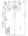
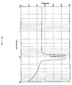
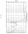
- Figs. 1 and 2 present the preferred controlled apparatus using this approach.
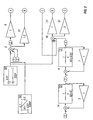
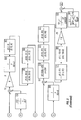
- Figs. 1 and 2 show functional block diagrams of the preferred electronics of the invention useful in conjunction with an IMU, with Fig. 2 showing the details of the IMU_Posn_Comp block of Fig. 1.
- Figs. 1 and 2 are also useful in performing a Matrixx/Matlab simulation of the invention, permitting one of ordinary skill in the art to verify its utility as described and claimed.
- Fig. 1 the preferred levitation height control system is illustrated. This includes the levitation height controller compensation (IMU_POSN_COMP), magnets and magnets drivers, vehicle and vehicle dynamics, guideway with guideway dynamics and IMU. Details of the levitation height controller are provided in Fig. 2.
- blocks 49, 47, 70, and 58 comprise a simplified magnet and magnet driver force controller.
- Block 25 is the vehicle lift force summing junction. Block 99 is simply the vehicle weight.
- the output of Block 25 is the net lift force applied to the vehicle.
- Block 11 is the inverse of vehicle inertia. Its output is vehicle lift acceleration for a rigid body.
- Block 18 is the vehicle dynamics. Its output is vehicle acceleration.
- Block 40 integrates the vehicle acceleration. Its output is vehicle rate.
- Block 41 integrates the vehicle lift rate. Its output is vehicle inertial vertical position. Blocks 43, 44, 77, 78, 80 and 81 are used to generate forces involved if the vehicle is in contact with the guideway.
- the guideway is modeled by blocks 36, 37, 49, 42, 16, 41 and 38.
- the output of block 16 is the guideway inertial position.
- the output of block 42 is the difference between the vehicle and guideway inertial positions, the magnetic gap.
- Block 65 is the IMU. Its output is the vehicle inertial acceleration.
- the IMU output is the inertial feedback and block 42 output is the gap measurement. These are the two feedbacks provided to the levitation height controller, IMU_POSN_COMP.
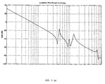
- a high bandwidth (approximately 5 Hz) inertial position loop is closed using the IMU as the feedback. Guideway modes are not coupled to the IMU.
- a low bandwidth (less than 1 Hz) gap loop is closed around the inertial loop eliminating IMU drift and allowing the vehicle to follow the changes in height in the guideway.
- Figure 2 comprises lift force generation, IMU loop closure, gap loop closure and gap command generation.
- the IMU output lift acceleration
- Blocks 14, 24, and 3 make up a low pass filter.
- the output of block 24 is the inertial lift rate estimate.
- Blocks 4, 2, and one comprise another low pass filter.
- the output of Block 2 is the lift inertial position estimate.
- Block 92 is the summing junction for the inertial height loop.
- Blocks 21, 91, 20 and 93 comprise a proportional plus integral ("P+I") compensator.
- Bloch 19 is a lead lag filter.
- Blocks 31, 5, 7, and 96 are structural filters for the vehicle dynamics.
- Block 89 sets the loop gain.
- Block 83 ramps the lift force up to just below vehicle weight.
- the crossover frequency for the inertial height control is approximately 5 Hz.
- the gap loop is closed in the upper half of Fig. 2.
- Blocks 90 and 62 are used to provide the gap command.
- the initial magnetic gap is 0.81" with the vehicle resting on its skids down on the track.
- block 62 generates the gap command.
- Blocks 8, 12, 13, and 15 comprise the P+I compensator for the gap loop.
- Blocks 10 and 67 provide the gap control loop with high low frequency gain.
- Blocks 56 and 55 are structural filters for the guideway modes.
- a high bandwidth levitation height loop is preferably closed using the IMU.
- This loop is completely decoupled from guideway modes.
- This loop provides disturbance rejection from wind gusts and high frequency track irregularities.
- a low bandwidth gap loop is closed around the IMU. This loop eliminates IMU drift and enables the vehicle to track the low frequency (e.g., grade changes) variations in the height of the guideway.
- the IMU preferably provides six degree of freedom information. Its angular outputs are preferably delta roll angle, delta pitch angle, and delta yaw angle. Very fine resolution angular data are preferably updated at 3600 Hz in the present invention. Lower frequency updates are acceptable.
- the linear outputs are preferably height acceleration, propulsive acceleration, and lateral acceleration. In the present invention, fine resolution acceleration data are preferably updated at 300 Hz.
Landscapes
- Engineering & Computer Science (AREA)
- Physics & Mathematics (AREA)
- Electromagnetism (AREA)
- Power Engineering (AREA)
- Transportation (AREA)
- Mechanical Engineering (AREA)
- Magnetic Bearings And Hydrostatic Bearings (AREA)
- Control Of Vehicles With Linear Motors And Vehicles That Are Magnetically Levitated (AREA)
- Control Of Position, Course, Altitude, Or Attitude Of Moving Bodies (AREA)
Abstract
Description
Claims (10)
- An apparatus for control of attractive magnetic levitation, said apparatus comprising:an inertial measurement unit; anda control loop employing output of said inertial measurement unit as a primary feedback of said control loop.
- The apparatus of claim 1 wherein said control loop additionally comprises means for elimination of inertial measurement unit drift.
- The apparatus of claim 2 wherein said means comprises a gap measurement loop operating at a bandwidth substantially lower than a primary loop of said control loop.
- The apparatus of claim 1 wherein guideway structural modes are decoupled from said control loop.
- The apparatus of claim 1 wherein outputs of said inertial measurement unit to said control loop comprise delta roll angle, delta pitch angle, delta yaw angle, height acceleration, propulsive acceleration, and lateral acceleration.
- A method for control of attractive magnetic levitation, the method comprising the steps of:operating an inertial measurement unit; andemploying output of the inertial measurement unit as a primary feedback of a control loop.
- The method of claim 6 wherein the employing step additionally comprises the step of eliminating inertial measurement unit drift.
- The method of claim 7 wherein the eliminating step comprises operating a gap measurement loop at a bandwidth substantially lower than a primary loop of the control loop.
- The method of claim 6 wherein guideway structural modes are decoupled from the control loop.
- The method of claim 6 wherein outputs of the inertial measurement unit to the control loop comprise delta roll angle, delta pitch angle, delta yaw angle, height acceleration, propulsive acceleration, and lateral acceleration.
Priority Applications (1)
| Application Number | Priority Date | Filing Date | Title |
|---|---|---|---|
| EP04076384A EP1595735A3 (en) | 2004-05-11 | 2004-05-11 | Inertial measurement unit based levitation control |
Applications Claiming Priority (1)
| Application Number | Priority Date | Filing Date | Title |
|---|---|---|---|
| EP04076384A EP1595735A3 (en) | 2004-05-11 | 2004-05-11 | Inertial measurement unit based levitation control |
Publications (2)
| Publication Number | Publication Date |
|---|---|
| EP1595735A2 true EP1595735A2 (en) | 2005-11-16 |
| EP1595735A3 EP1595735A3 (en) | 2006-11-08 |
Family
ID=34928204
Family Applications (1)
| Application Number | Title | Priority Date | Filing Date |
|---|---|---|---|
| EP04076384A Withdrawn EP1595735A3 (en) | 2004-05-11 | 2004-05-11 | Inertial measurement unit based levitation control |
Country Status (1)
| Country | Link |
|---|---|
| EP (1) | EP1595735A3 (en) |
Family Cites Families (2)
| Publication number | Priority date | Publication date | Assignee | Title |
|---|---|---|---|---|
| US3736880A (en) * | 1971-04-19 | 1973-06-05 | Rohr Industries Inc | Feedback control circuit for magnetic suspension and propulsion system |
| US4969401A (en) * | 1989-03-14 | 1990-11-13 | Kolm Henry H | Active damping system for resiliently levitated vehicles |
-
2004
- 2004-05-11 EP EP04076384A patent/EP1595735A3/en not_active Withdrawn
Also Published As
| Publication number | Publication date |
|---|---|
| EP1595735A3 (en) | 2006-11-08 |
Similar Documents
| Publication | Publication Date | Title |
|---|---|---|
| US20190255954A1 (en) | Magnetic Levitation of Vehicles | |
| Yau | Response of a maglev vehicle moving on a series of guideways with differential settlement | |
| US5329077A (en) | Elevator ride quality | |
| WO2009046064A4 (en) | Track switching for a magnetically levitated transportation system and method | |
| Masoud et al. | Sway reduction on container cranes using delayed feedback controller | |
| CN112078376B (en) | A kind of permanent magnet maglev train steering control method and system | |
| CN113189877B (en) | A bridge crane anti-sway positioning control method with distributed mass load | |
| CN109094421A (en) | The multi-point cooperative suspension control system of suspension type magnetic suspension train | |
| US20100199876A1 (en) | Guideway switch apparatus for magnetically levitated vehicles | |
| Tan et al. | Automatic steering based on roadway markers: From highway driving to precision docking | |
| CN102323825A (en) | A Torque Compensation Control Method of DGMSCMG System During Spacecraft Maneuvering | |
| US20040221762A1 (en) | Inertial measurement unit based levitation control | |
| US6871597B1 (en) | Magnetically levitated transporter | |
| CN109891182B (en) | Height control along segmented tracks | |
| Jayawant et al. | Feedback control systems for dc electromagnets in passenger-carrying vehicles | |
| Alberts et al. | Stable levitation control of magnetically suspended vehicles with structural flexibility | |
| EP3649005A1 (en) | Path correction of a vehicle relative to projected magnetic flight path | |
| CN109298647A (en) | High-speed maglev train suspension control method based on lap joint structure whole | |
| Bi et al. | Integrated Levitation-Propulsion-Guidance Implementation and Operation Control for Active-Steering Maglev Car | |
| CN111532341A (en) | A vehicle with a suspended body and a control method thereof | |
| CN112767801B (en) | Traveling type magnetic suspension demonstration system and float static suspension and traveling control method | |
| Nagurka et al. | A superconducting maglev vehicle/guideway system with preview control: Part I—Vehicle, guideway, and magnet modeling | |
| Fei | A class of adaptive sliding mode controller with integral sliding surface | |
| Hanasoge | Stability analysis, modeling, simulation and experimental testing of an EMS Maglev system with structural flexibility | |
| Long et al. | Design of a small-scale prototype for a stabilized permanent magnet levitated vehicle |
Legal Events
| Date | Code | Title | Description |
|---|---|---|---|
| PUAI | Public reference made under article 153(3) epc to a published international application that has entered the european phase |
Free format text: ORIGINAL CODE: 0009012 |
|
| AK | Designated contracting states |
Kind code of ref document: A2 Designated state(s): AT BE BG CH CY CZ DE DK EE ES FI FR GB GR HU IE IT LI LU MC NL PL PT RO SE SI SK TR |
|
| AX | Request for extension of the european patent |
Extension state: AL HR LT LV MK |
|
| PUAL | Search report despatched |
Free format text: ORIGINAL CODE: 0009013 |
|
| AK | Designated contracting states |
Kind code of ref document: A3 Designated state(s): AT BE BG CH CY CZ DE DK EE ES FI FR GB GR HU IE IT LI LU MC NL PL PT RO SE SI SK TR |
|
| AX | Request for extension of the european patent |
Extension state: AL HR LT LV MK |
|
| 17P | Request for examination filed |
Effective date: 20070323 |
|
| AKX | Designation fees paid |
Designated state(s): AT BE BG CH CY CZ DE DK EE ES FI FR GB GR HU IE IT LI LU MC NL PL PT RO SE SI SK TR |
|
| 17Q | First examination report despatched |
Effective date: 20070730 |
|
| STAA | Information on the status of an ep patent application or granted ep patent |
Free format text: STATUS: THE APPLICATION IS DEEMED TO BE WITHDRAWN |
|
| 18D | Application deemed to be withdrawn |
Effective date: 20071211 |