EP1594305A1 - Procédé et dispositif de conversion d'espace de couleur par interpolation tridimensionnelle - Google Patents
Procédé et dispositif de conversion d'espace de couleur par interpolation tridimensionnelle Download PDFInfo
- Publication number
- EP1594305A1 EP1594305A1 EP05290975A EP05290975A EP1594305A1 EP 1594305 A1 EP1594305 A1 EP 1594305A1 EP 05290975 A EP05290975 A EP 05290975A EP 05290975 A EP05290975 A EP 05290975A EP 1594305 A1 EP1594305 A1 EP 1594305A1
- Authority
- EP
- European Patent Office
- Prior art keywords
- coordinates
- interpolation
- space
- representative
- image
- Prior art date
- Legal status (The legal status is an assumption and is not a legal conclusion. Google has not performed a legal analysis and makes no representation as to the accuracy of the status listed.)
- Withdrawn
Links
- 238000000034 method Methods 0.000 title claims abstract description 81
- 230000009466 transformation Effects 0.000 title 1
- 238000006243 chemical reaction Methods 0.000 claims abstract description 93
- 239000000203 mixture Substances 0.000 claims abstract description 92
- 238000004364 calculation method Methods 0.000 claims abstract description 74
- 238000005070 sampling Methods 0.000 claims description 51
- 230000009182 swimming Effects 0.000 claims 1
- 238000007792 addition Methods 0.000 description 5
- 230000015556 catabolic process Effects 0.000 description 3
- 238000006731 degradation reaction Methods 0.000 description 3
- 238000010586 diagram Methods 0.000 description 2
- 230000006870 function Effects 0.000 description 2
- 239000003086 colorant Substances 0.000 description 1
- 235000021183 entrée Nutrition 0.000 description 1
- 230000014759 maintenance of location Effects 0.000 description 1
- 238000013507 mapping Methods 0.000 description 1
- NTHWMYGWWRZVTN-UHFFFAOYSA-N sodium silicate Chemical compound [Na+].[Na+].[O-][Si]([O-])=O NTHWMYGWWRZVTN-UHFFFAOYSA-N 0.000 description 1
Images

Classifications
-
- H—ELECTRICITY
- H04—ELECTRIC COMMUNICATION TECHNIQUE
- H04N—PICTORIAL COMMUNICATION, e.g. TELEVISION
- H04N1/00—Scanning, transmission or reproduction of documents or the like, e.g. facsimile transmission; Details thereof
- H04N1/46—Colour picture communication systems
- H04N1/56—Processing of colour picture signals
- H04N1/60—Colour correction or control
- H04N1/6016—Conversion to subtractive colour signals
Definitions
- the present invention applies to the fields of image processing and electronics.
- the invention applies more particularly to the conversion of color space of an image, when establishing signals representative of the colors of an image to allow, for example, its printing by a printing device or its display by means display (LCD, CRT or plasma screens).
- the present invention relates to a method of converting color space by interpolation three-dimensional chromatic components of the pixels of an image.
- the present invention also relates to the architecture of the device the implementation of the method according to the invention.
- An image is represented, in image processing systems, a set of successive lines consisting of successive points (or pixels).
- the representative values of the two-dimensional arrangement and the chromatic compositions and / or luminance of the pixels define the image in its entirety.
- the chromatic composition of a given pixel of a image can be represented in different color spaces, including dimensions each correspond to a chromatic component and / or luminance.
- the color composition of a pixel can be represented in a RGB color space (for the English “Red Green Blue “, that is Red Green Blue) or CMY (for English “Cyan Magenta Yellow”, that is Cyan Magenta Yellow) or type CMYK (for the English “Cyan Magenta Yellow blacK", that is Cyan Magenta Yellow Black).
- RGB color space for the English “Red Green Blue”
- CMY for English "Cyan Magenta Yellow", that is Cyan Magenta Yellow
- type CMYK for the English “Cyan Magenta Yellow blacK”
- Cyan Magenta Yellow Black Each dimension of these spaces corresponds to a chromatic component.
- LAB space for Luminance English, A and B color channels
- pixels of an image are
- the representative signals in the image processing systems of the coordinates of the points representative of different chromatic compositions are encoded on a certain number of bits.
- a given chromatic composition in a given representation space, can be encoded on 8 bits per chromatic component (that is to say 8 bits per dimension of the representation space).
- Each chromatic component (that is to say, each dimension of the representation space) of a given pixel can therefore take 256 values.
- the representation space has three dimensions, it would require a conversion table containing 256 3 values to be able to convert each of the possible coordinates in this representation space.
- One solution is to sample the possible coordinates in the representation space in a sampling step, preferably multiple of 2, so as to reduce the number of possible coordinates.
- this solution thus makes an approximation of the different representative points of the different possible chromatic compositions.
- the coordinates of a point are rounded by this approximation.
- the points are thus assimilated to cubes in which they are inscribed, the set of these cubes covering the entirety of the representation space. For this, it suffices for example to take only a certain number of bits of high weight among the bits on which are coded the coordinates of the points representative of the different chromatic compositions.
- These high-order bits correspond to signals representative of the coordinates of the cubes of the representation space and the low-order bits represent the precise coordinates of the points within these cubes.
- each cube will be defined by the coordinates of a point of origin of the cube and by the coordinates of the points of origin of the adjacent cubes.
- the number of most significant bits used at the input of the conversion table will determine the number of cubes used to cover the entire representation space in the conversion table. The numbers of high and low bits therefore depend on the sampling interval used to establish the color space conversion table.
- Each entry of the table corresponds to the coordinates of the point of origin of a cube.
- Each cube being defined by the coordinates of its point of origin and the points of origin of the adjacent cubes, the 8 vertices of a cube will be defined by 8 entries of the conversion table.
- This solution allows, on the one hand, to accelerate the calculation of the coordinates of the representative points of chromatic compositions using size conversion tables on the other hand, to maintain the precision of the definition of the chromatic composition by estimating the error realized by the approximation due to the use of the conversion table.
- the most significant bits among the bits coding the coordinates of a point representative of a composition chromatic of a given pixel are used to determine in which cube of space this point is inscribed.
- a conversion table then allows convert the coordinates of this cube from a representation space to a other.
- the least significant bits are used to determine, by interpolation three-dimensional, the distance separating this point from the 8 vertices of the cube in which he is registered.
- This three-dimensional interpolation using the 8 vertices of the cube, in which is inscribed the point to interpolate, is called tri-linear. It makes it possible to calculate interpolation coefficients to be applied on the coordinates of each vertex of the cube, to determine the exact coordinates of the representative point of the chromatic composition of the pixel. The coordinates of the vertices of the cube, in the new space of representation, are determined through the conversion table. The interpolation coefficients then make it possible to determine the coordinates exact of the point representative of the chromatic composition of the given pixel, in the new space of representation.
- the present invention aims to overcome certain disadvantages of the prior art by providing a color space conversion method by three-dimensional interpolation, according to different calculation methods chosen by the user according to criteria of quality and speed, for allow the conversion of representative points of the composition chromatic pixels of an image in a multidimensional space of initial representation in points representative of the chromatic composition pixels of the image into another multidimensional space of representation, of which at least some dimensions correspond to chromatic and / or luminance components.
- a color space conversion method by interpolation of the coordinates of each of the representative points of the chromatic composition of the pixels of an image, from a space multi-dimensional initial representation to at least one other space multidimensional representation, called final, of which at least some dimensions correspond to chromatic components, characterized, on the one hand, in that it is implemented by an electronic circuit interpolation implemented in an image processing system and, on the other hand, on the other hand, in that it comprises a step of input of choice, by a user, thanks to input means of the image processing system, at least a preferred criterion among at least criteria of speed and quality of the color space conversion, this choice step resulting in the selection of a three-dimensional interpolation method, among at least three methods, achievable by the electronic circuit, all consisting of one calculation of polyhedral interpolation coefficients making it possible to determine the coordinates of the points representative of the chromatic composition of pixels of an image, based on the vertex coordinates of polyhedra in which these points coordinates are understood, the
- the methods of polyhedral interpolation the electronic circuit is four and different by the nature of the polyhedra used, among either cubes or tetrahedra, either prisms or pyramids.
- the user's input step of choice of the preferred criterion results, in the image processing system, by a selection of one of four values stored in a register of configuration, each value corresponding to a type of interpolation polyhedral, the selection of one of these values allowing a PLC of the image processing system to send commands from multiplexing to multiplexers of the interpolation electronics three-dimensional, these multiplexing commands allowing the circuit to perform the calculation, according to the interpolation method selected polyhedral, interpolation coefficients and coordinates of the representative point, in the final performance area, of the chromatic composition and / or luminance of the pixels of the image.
- the method also comprises a step of choice by the user, thanks to input means of the system of image processing, of at least one final representation space among a plurality of representation spaces, thanks to a plurality of tables of conversion stored in storage means of the system of image processing, the consultation of each of these tables allowing the determination of the coordinates of the vertices of the polyhedron in which find the representative point of the chromatic composition of a given pixel of the image, in each dimension of the space of representation final, from the coordinates of the vertices of this polyhedron in each dimensions of the initial representation space, according to a step Sampling coordinates in the initial and final spaces, corresponding to the entry step of these tables, this step of choice allowing the use, by the means of calculation of the system of image processing, the sampling rate and the coordinates of the vertices of polyhedra, for the calculation of interpolation coefficients and coordinates of the representative point of the pixel in the representation space final.
- the step of consulting one of the tables of conversion results in the determination of the coordinates, in each dimensions of the final performance space, summits of the polyhedron corresponding to the coordinates of the vertices of the polyhedron in which are included the coordinates of the representative point of the chromatic composition of a pixel of the image in the space of initial representation, this determination then allowing the calculation of the coordinates of the point representative of the chromatic composition of the pixel in the final performance space.
- the step of determining the polyhedron in which are the coordinates of the representative point of the chromatic composition of a pixel of the image, made according to the chosen three-dimensional interpolation calculation method, when the polyhedron is not a cube, by comparison of the values of the weight bits weak among these signals, in each of the dimensions of the space of initial representation allows to define in which polyhedron are understood the coordinates of this point, among the plurality of possible polyhedra for the same type of given polyhedral interpolation and, consequently, define the multiplexing commands to be sent by the PLC to the multiplexers of the interpolation circuit, to calculate the interpolation coefficients and the coordinates of the point representative of the pixel in process, in the final performance space.
- a second object of the invention is to propose an electronic circuit whose architecture allows the realization of different calculation methods of polyhedral interpolation, for the implementation of the method according to the invention.
- an electronic circuit of polyhedral interpolation allowing a color space conversion, characterized in that includes multiplexers whose multiplexing commands are determined according to signals from a PLC controlled by a configuration register, the arrangement of these multiplexers allowing, according to the multiplexing commands sent by the PLC, execution, by means of interpolation coefficient calculations, of at least a polyhedral interpolation calculation method chosen from three different methods achievable by the configurable electronic circuit of evolutionary way by the automaton.
- the circuit comprises inputs receiving, of the image processing system, signals representative of coordinates of points representative of chromatic compositions of pixels of an image, the calculations made by the circuit on these inputs allowing, according to the multiplexing commands, a conversion of color space, through the development of signals representative of coordinates of points representative of chromatic compositions of pixels of an image, in a multidimensional space of representation final, from the signals representative of the coordinates of these points in a multidimensional space of initial representation and signals representative of the calculated interpolation coefficients.
- the architecture of the electronic circuit allows the conversion of coordinates of a point representative of the chromatic composition of a given pixel of an image, from a space three-dimensional initial representation to a four-dimensional space of final representation, according to one of four interpolation methods polyhedra differing in the nature of the polyhedra used, among cubes, either prisms, pyramids or tetrahedra, the coordinates of the vertices of these polyhedra being determined according to a step sampling of the coordinates of the representative point of the composition chromaticity of the pixel of the image, this sampling step corresponding to the no entry of at least one conversion table of the coordinates of vertices of polyhedra in an initial representation space in coordinates of polyhedron vertices in a representation space final.
- the interpolation electronic circuit has a first block, called interpolation coefficient calculation, composed of subtracters, multipliers, registers and multiplexers, these multiplexers receiving multiplexing commands from the automaton associated with the interpolation circuit, which thus controls the sequence of operations and calculations made to determine the coefficients interpolation vertices successively during processing.
- the coefficient calculation block interpolation allows, under the control of the multiplexing controls sent to the multiplexers by the PLC, to calculate the coefficients interpolation by subtraction and / or multiplication of signals between them representative of the coordinates of the representative point of the composition chromatic of the pixel being processed in the dimensions of the space Initial Representation Required for the Interpolation Method selected and / or signals representative of the sampling rate of these coordinates, the interpolation coefficients thus calculated being then stored in a storage register of the interpolation coefficients of the interpolation circuit.
- the interpolation electronic circuit has a second block, called color space conversion, composed, multipliers, adders, dividers, registers and multiplexers, this block receiving as input, on the one hand, the coefficients interpolation stored in the coefficient storage register interpolation circuit and, on the other hand, the signals representatives, in the final performance area, of the coordinates of the vertices of the corresponding polyhedron, according to the conversion table, polyhedron in which are included, in the initial representation space, the coordinates of the representative point of the chromatic composition of the pixel being processed.
- color space conversion composed, multipliers, adders, dividers, registers and multiplexers
- color space conversion block of the electronic interpolation circuit allows, under the control of multiplexing commands sent to the multiplexers by the PLC, calculate, in each of the dimensions of the final representation space, the coordinates of the representative point of the chromatic composition of the pixel being processed by calculating the sum of the products of each interpolation coefficients with the coordinates of one of the vertices of the corresponding polyhedron, according to the conversion table, in the space of final representation, with the selected polyhedron in the representation space initially, and then by dividing that sum, either by the sampling step at cube when the polyhedron used is a cube, either by the sampling step squared when the polyhedron used is a prism or a pyramid, either by the no sampling when the polyhedron used is a tetrahedron.
- a third object of the invention is to propose a system of image processing for implementing the method according to the invention.
- an image processing system allowing the color space conversion according to different calculation methods of polyhedral interpolation, comprising calculation means and means for acquiring signals representative of an image, characterized, on the one hand, in that it comprises an electronic interpolation circuit comprising multiplexers controlled by a PLC, whose multiplexing are determined, based on signals from a configuration register of the image processing system, to enable the performing at least three methods of calculating polyhedral interpolation by interpolation coefficient calculations and, on the other hand, by includes storage means in which at least one storage is stored a conversion table mapping coordinates of vertices of polyhedra, in an initial multidimensional space of representation of the chromatic composition of the pixels of an image, with vertex coordinates of polyhedra in a space multidimensional representation of the chromatic composition of the pixels of an image, according to a sampling step of coordinates that corresponds to the entry step in the table and that is used for the determining the coordinates of the vertices of the polyhedra and for calculating interpolation
- the system includes means for input allowing the user to enter a choice of a preferred criterion from among less criteria of quality and speed, the selection of this favorite criterion resulting in the selection of a value of the signals of the configuration register of the system determining the multiplexing commands sent by the PLC to the multiplexers of the interpolation electronics polyhedric, this choice determining the nature of the polyhedra used in the polyhedral interpolation calculation, the calculation means of the image processing allowing the determination of the coordinates of vertices of the polyhedron in which are included the coordinates of the point representative of the chromatic composition of a given pixel of the image, in the multidimensional space of initial representation.
- the input means allow also the seizure of a choice of a multidimensional space of final representation of the chromatic composition of the pixels of the image, this entry allowing the choice of the use of one of the tables of conversion of color space stored in the storage means of the image processing system.
- the system storage means allow the storage of signals representative of the composition chromaticity of the pixels of the image, in a multidimensional space of representation, these signals being acquired thanks to the acquisition means of signals representative of an image and used as input to the integrated circuit of polyhedral interpolation and input of the space conversion table chosen color, to allow the calculation of coordinates of points representative of the chromatic composition of a given pixel of the image by summation of the product of the interpolation coefficients, each with the coordinates of one of the vertices of the polyhedron, in a space multidimensional initial representation and then into a space multidimensional representation.
- the present invention of process, circuit and conversion system of color space by polyhedral interpolation consists of a conversion coordinates of the points representative of the chromatic composition successive pixels (11) of an image (1) being processed, since a space (2) multidimensional initial representation to a space (3) of final multidimensional representation, thanks to an electronic circuit (10) implemented in a system (100) of image processing allowing the setting implementation of the steps of the method according to the invention.
- the user may wish to choose the space (3) final representation, in order to allow the sending of the signals representative of the image (1) thus converted to different devices display or print.
- the method according to the invention comprises a step of a choice of the final representation space (3), thanks to means (15) for inputting the image processing system (100).
- This step choice of the final representation space (3) will result in the use of one of the color space conversion tables (4) stored in the means (40) for storing the image processing system (100).
- These tables (4) each allow the conversion of a number of coordinates of points from an initial representation space to a final performance space, according to a sampling step (S) of the coordinates of these points.
- These sampling steps (S) define the number of table (4) conversion entries and the accuracy of the conversions they allow.
- Sampling coordinates of points, according to this step (or "step” in English) is an approximation of these coordinates. This approximation is done using only one number of most significant bits among the signals representative of coordinates of the points (20) representative of the pixels (11) being treatment.
- the method also comprises a step of input of choice of the preferred criterion among several criteria of speed and quality of treatment of the image (1). Depending on the quality and speed desired by the user, he can choose the treatment to be performed by the system (100).
- This stage of user input of the choice of the preferred criterion thanks to the means (15) for inputting the image processing system (100) is translated by selecting one of the different methods of polyhedral interpolation achievable by the electronic circuit (10) of the treatment system (100) image.
- these methods polyhedral interpolation that can be performed by the electronic circuit (10) are number of four and differ in the nature of the polyhedra (25) used, among either cubes, or tetrahedra, or prisms, or pyramids.
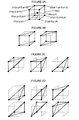
- FIGS. 2A to 2D represent the various polyhedra used by the different interpolation methods achievable by the circuit (10).
- the figure 2A represents a cube (25) of index i, in which the coordinates (x, y, z) of the point (20) representative of the chromatic composition of the pixel (11) in course of treatment are included.
- the sampling step (S) of the coordinates (x, y, z) of the points (20) results in the approximation of these coordinates (x, y, z) at the coordinates (xi, yi, zi) of the origin point of this cube (25) of index i.
- the other vertices (21) of this cube (25) of index i have coordinates defined according to the sampling step (S), in each dimensions of the representation space.
- the index cube i + 1 along the abscissa axis will have a point of origin as a vertex (21) abscissa x (i + 1), equal to xi + S.
- the sampling step (S), used here for determine the coordinates of the vertices (21) of the polyhedron in which the coordinates of the point to interpolate are included, depends on the sample which had been used for the creation of the tables (4) of conversion before storage in the memory means (40).
- the tables (4) conversion, using this sampling step (S) as no entry into the table, allow the conversion of the coordinates of each of these vertices (21) from the space (2) of initial representation to the coordinates of corresponding vertices (31) in the space (3) of final representation.
- the vertex (21) of coordinates (xi + S, yi, zi) corresponds, in the conversion table (4), to the entry of index i + 1 according to the axis of the abscissa and index i according to the other two axes.
- a type of polyhedron (25) will be used for conversion.
- means for calculating the image processing system (100) make it possible to determine in which polyhedron the coordinates (x, y, z), among one of the polyhedra corresponding to the chosen interpolation method.
- the interpolation will use cubes (FIG.
- the process can use the tetrahedral interpolation method and the calculation means of the system (100) will determine in which of the six tetrahedrons of the figure 2D are the coordinates (x, y, z) of the point (20) representative of the chromatic composition of the pixel (11) being processed.
- the calculation means of the system (100) performs a comparison between the coordinates (x, y, z) of the point (20) in each of the dimensions. For this, the least significant bits, among the signals representative of the coordinates of the point (20) in the space (2) of representation, are used. For example, if x ⁇ y ⁇ z, then point (20) is inscribed in the first tetrahedron of Figure 2D.
- the different relationships inequality between the coordinates (x, y, z) of the points (20) and the correspondence with the polyhedra in which they are inscribed, are data in the attached table.
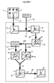
- the method according to the invention implements the steps shown. in FIG. 1, iterated for each of the successive pixels of the image (1).
- the system accesses successively to the signals representative of the pixels of the image. The process therefore starts with access (51) to the signals representative of the pixel (11) in course of treatment.
- These signals can be represented by a dot (20) whose coordinates are representative of the chromatic composition of the pixel (11) being processed in an initial representation space (2).
- the means (15) for entering the system (100) allow the user to choose the desired final performance space and the quality or speed with which which he wants the process to proceed.
- User selection of the criterion among the criteria of speed and quality is reflected in the system (100) by selecting one of four stored values in a configuration register (70, FIG. 3), each corresponding value to a type of polyhedral interpolation.
- the selection of one of the values of the register (70) for configuration allows a controller (50) of the system (100) image processing to send multiplexing commands (59) to multiplexers (60) of the electronic interpolation circuit (10) three-dimensional. These multiplexing controls (59) allow the circuit (10) electronics to achieve one of the polyhedral interpolation methods.
- This step therefore consists of a selection (52) of a type of polyhedron (25) to use among cubes, prisms, pyramids or tetrahedra.
- the calculation means of the system (100) then make it possible to determine (53) the polyhedron (25) in which is the point (20) representative of the chromatic composition of the pixel (11) in the representation space (2) initial.
- the selection of most significant bits among the signals representative of coordinates of this point (20), according to the sampling step (S), allows to determine the vertex (21) of origin of the cube (25) of index i in which point (20) is inscribed.
- the coordinates of the vertices (21) of the selected polyhedron (25) allow, on the other hand, the consultation (555) of a conversion table (4), according to the final representation space (3) chosen.
- This table (4) conversion stored in the means (40) for storing the system (100) allows, according to the index (41) of entry into the table of the selected polyhedron (25), the determining (56) the coordinates of the vertices (31) of the polyhedron (35) corresponding, in the space (3) of final representation, to the vertices (21) polyhedron (25) selected in the initial representation space (2).
- the electronic interpolation circuit (10) then performs the multiplication (57) coordinates of each of these vertices (31) with the coefficient (22) of interpolation corresponding to this vertex according to the interpolation method selected, then the sum (58) of these products.
- This sum is then divided by the sampling step (S) to the cube when the polyhedron (25) used is a cube, either by the sampling step (S) squared when the polyhedron (25) used is a prism or a pyramid, either by the sampling (S) when the polyhedron (25) used is a tetrahedron.
- This division of the sum of the products makes it possible to determine the coordinates of the representative point (30) in the final representation space (3) of the chromatic composition of the pixel (11) being processed.
- Signals, representative of the chromatic composition of the pixel (11), thus converted can then be stored temporarily in a memory, for example in the means (40) for storing the system (100), with a view to additional treatment by another device or be directly transmitted to a processing, display or printing device.
- the signals representative of the next pixel of the image (1) will then also be processed according to the steps outlined above.
- the method according to the invention is implemented by a system (100) of image processing in which an electronic circuit (10) is implemented interpolation according to the invention.
- This circuit (10) allows the implementation of four different interpolation methods, using either cubes or prisms, either pyramids or tetrahedra.
- the use of one of the four methods are realized thanks to the commands (59) of multiplexing sent by the controller (50) of the system (100) according to the selection of one of the values of the register (70) of configuration, following the entry of the choice the user's preferred criterion among criteria of quality and speed of the treatment, thanks to the means (15) for entering the system (100).
- the comparison between them of the coordinates of the point (20) representative of the chromatic composition of the pixel (11) being processed, in each dimensions of the initial representation space (2) makes it possible to determine in which polyhedron these coordinates are included, among the plurality of possible polyhedra for the same type of interpolation given polyhedron.
- a comparator (90) implemented in the system (100) of image processing uses only the values of the least significant bits, between the different dimensions (x, y and z) of the representation space (2) initial, to determine the polyhedron (25) in which these coordinates are included.
- the controller (50) sends multiplexing commands (59) to the multiplexers (60) of the electronic interpolation circuit (10) to calculate the interpolation coefficients (22).
- This calculation of the coefficients (22) interpolation is achieved thanks to the fact that the inputs of the multiplexers (60) receive the value of the sampling step (S) used in the tables (4) of conversion stored in the storage means (40) and / or the values some of the coordinates (x, y, z) of the point (20).
- Orders (59) from multiplexing sent by the PLC (50) will allow to control the use of the different inputs of the multiplexers (60) and to direct the processing performed by the circuit (10) to the calculation (550) of the coefficients (22) corresponding interpolation method to the chosen interpolation method.
- the means for acquiring representative signals of an image are not shown either in Figure 3 because they do not do not characterize the system according to the invention.
- the system (100) comprises storage means (40) in which at least one storage is stored conversion table (4) matching coordinates of vertices (21) of polyhedra (25), in an initial multidimensional space (2) for representing the chromatic composition of the pixels of an image (1), with coordinates of vertices (31) of polyhedra (35), in a space (3) final multidimensional representation of the chromatic composition pixels of the image (1), according to the sampling step (S) of the contact information.
- the input means (15) allow the user to choose the space (3) of final representation that it wishes to obtain and therefore the table (4) conversion that must be used.
- the interpolation circuit (10) comprises multiplexers (60), subtracters (61), multipliers (62), adders (63), dividers (64) and storage registers (71 to 81) provisional.
- the architecture of the interpolation circuit (10) allows the different calculations of interpolation coefficients (22) corresponding to different polyhedral interpolation methods.
- This circuit (10) comprises a block of calculation of interpolation coefficients, which allows, according to the values selected from the configuration register (70), to obtain signals representative of the interpolation coefficients (22) corresponding to the vertices (21) of selected polyhedron (25), according to the sampling step (S) used in tables (4) and according to the coordinates of these vertices (21) and the point (20) representative of the chromatic composition of the pixel (11) during processing, in the initial representation space (2).
- This circuit (10) also includes a color space conversion block, which allows to calculate the coordinates of the point (30) representative of the chromatic composition of the pixel (11) being processed, in space (3) of the final representation, based on the interpolation coefficients (22) and the coordinates, derived from the conversion table (4), the vertices (31) of the corresponding polyhedron (35) in the final representation space (3) to polyhedron (25) selected in the initial representation space (2).
- the inputs of the multiplexers (60) of the coefficient calculation block the interpolation circuit (10) receive, means (40) for storing the image processing system (100) on the one hand, and a number of least significant bits among the representative signals of coordinates (x, y, z) of the point (20) representative of the composition chromaticity of the pixel (11) being processed and, on the other hand, representative of the sampling interval (S) of these coordinates.
- This first block consists of a first row of four multiplexers (60) with three entries each.
- Three of these four multiplexers receive on their inputs, signals representative of the sampling interval (S) and coordinates of the point (20) in two dimensions of the space (2) of representation (ie y and z for the first multiplexer, or x and z for the two other multiplexers).
- the fourth multiplexer of this first row receives on its inputs the signals representative of the coordinates of the point (20) in the three dimensions (x, y and z) of the space (2) of initial representation. Its output is sent to a multiplier (62) of the first row to multiply the selected entry, thanks to multiplexing commands (59) by the signals representative of the pitch sampling (S).
- each of the first three multiplexers from the first row is sent to a respective subtractor (61) subtracting the selected entry with the commands (59) of multiplexing, by the signals representative of the coordinates of the point (20), each respectively in a dimension of the space (2) of initial representation (x for the first, y for the second and z for the third).
- the output of these three subtractors (61) is sent to a second row of three multiplexers (60).
- the four entries of the two first multiplexers in the second row receive the output of both first subtractors (61) of the first row, the value 1 and the value signals representative of the coordinates of the point (20) in both dimensions of the initial space (2) used in the adjacent multiplexer of the upper row (ie x and z for the first, y and z for the second).
- the output of these two four-input multiplexers is sent to a multiplier (62) whose output is sent to a storage register (71).
- the third multiplexer (60) of the second row has three inputs receiving the output of the third subtractor (61) of the first row, the value 1 and the value of the signals representative of the coordinates of the point (20) in a single dimension (z) of the initial space (2).
- This third multiplexer (60) of the second row is sent to a multiplexer (60) of a third row, which has two inputs and receives on its other input, the multiplier (62) of the first row, the signal representing the product of the output of the fourth multiplexer of the first row, with the signals representative of the sampling interval (S).
- the output of the latter multiplexer (60) with two inputs of the third row is sent to a storage register (72).
- Each output of both storage registers (71, 72) are sent to a subtractor (61) at a time and a multiplier (62), the output of each of which is sent to a last multiplexer (60), interpolation coefficient calculation block, two entries.
- This last multiplexer of the block is sent to a register (73) for storing the interpolation coefficients (22) calculated using to the operations carried out following the multiplexing commands (59) successive messages sent by the controller (50) to the multiplexers (60) of the architecture described above.
- This architecture of the block of calculation of the interpolation coefficients therefore, according to the interpolation method chosen, the calculations of the interpolation coefficients (22) as defined in the table provided in Annex.
- the 4 coefficients to be calculated are S - x, x - y, y - z and z.
- the multiplexing commands (59) successively sent by the automaton (50) to the coefficient calculation block allow the selection of the different inputs of the multiplexers (60) for obtain the successive coefficients.
- the commands (59) multiplexing will initially allow to obtain the coefficient S - x. To do this, the multiplexing commands (59) select, on the first multiplexer (60) of the first row, the input receiving the S value of the sampling interval, so that the first subtractor (61) can obtain the value S - x. Orders (59) the multiplexer will select, on the first multiplexer (60) of the second row, the input receiving this value S - x of the subtractor (61).
- the multiplexing controls (59) will select, on the second multiplexer (60) of the second row, the input receiving the value 1 of way to allow the multiplication of the value S - x with 1 by the multiplier (62) and the retention of the S - x value in the provisional register (71) (whatever the commands sent on the multiplexer of the row higher).
- the multiplexing controls (59) will select, on the third multiplexer (60) of the second row, the input receiving the value 1 (whatever the commands sent on the multiplexer of the row higher).
- the commands will select on the multiplexer of the third row, the input receiving this value 1 so as to allow the storing the value 1 in the provisional register (72).
- the multiplier (62) will then realize the multiplication of the value S - x with 1, then the selection of this value, by the multiplexing commands (59) on the last multiplexer (60) of the coefficient calculation block will allow its conservation in the register (73) for storing the coefficients. Then the commands (59) multiplexing will change according to the calculation sequence of coefficients, for example, to calculate the coefficient x - y. These commands (59) select, on the second multiplexer of the first row, the input x so as to allow its subtraction by the value y by the subtractor (61).
- the selection of the value 1 on the three multiplexers of the second row (whatever the commands sent to the other multiplexers in the first row), thanks to the multiplexing commands (59), will allow the conservation of this value and its multiplication with the value 1 by the multiplier (62) in release of provisional registers (71, 72).
- the selection on the last multiplexer of the block, of the input receiving the result of this multiplication will store this x - y value in the register (73).
- multiplexing controls (59) will allow the calculation of the coefficient y - z through the selection of the input y on the second multiplexer (60) of the second row and input 1 on the first multiplexer (60) of the second row (regardless of the orders placed on the multiplexers in the upper row).
- Orders (59) select, on the third multiplexer (60) of the second row, the input receiving the value z then the input receiving this value on the multiplexer (60) of the third row (whatever the commands sent to the multiplexers in the first row).
- the subtractor (61) will perform the subtraction y - z and the commands (59) sent on the last multiplexer (60) of the coefficient calculation block will allow the conserving this value y - z and storing it in the register (73).
- the last z coefficient will be calculated by selecting the input receiving the value z on the third multiplexer (60) of the second row and selecting the input receiving the value 1 on the first and second multiplexers (60) of the second row (whatever the controls sent to the multiplexers in the first row).
- the register (71) then contains the value 1 and the selection on the multiplexer of the third row, of the input receiving the z value of the third multiplexer of the second row will allow the storage of the z value in the registry (72) provisional.
- the multiplexing commands (59) sent successively by the automaton (50) to the different multiplexers (60) of the block for calculating the coefficients (22) in the interpolation circuit (10) have allowed the calculation of the 4 interpolation coefficients necessary for the interpolation tetrahedral type 1 chosen from the values chosen in the register (70) according to the coordinates of the point to be interpolated and the choice of the interpolation speed.
- the space conversion block of color of the interpolation circuit (10) will allow the multiplication of each of these coefficients with the coordinates, in the representation space final, from the vertex to which it corresponds in the selected type 1 tetrahedron.
- the color space conversion block of the interpolation circuit (10) receives on its inputs, the different interpolation coefficients (22) calculated and stored in the coefficient storage register (73) (22). This color space conversion block also receives, on the inputs of its multiplexers, the signals representative of the coordinates, in each of the dimensions of the final representation space (3), of the vertices (31, FIG. 1) of the polyhedron. (35, FIG. 1) corresponding, according to the conversion table (4) stored in the storage means (40) of the system (100), to the polyhedron (25, FIG. 1) selected in the space (2) of FIG. initial representation.
- This color space conversion block is divided into four identical columns for calculating, in four dimensions, signals representative of the coordinates of the points (30) representative of the chromatic composition of the pixel (11) being processed, in the spaced (3) final representation.
- the coordinates of each vertex (31) of the polyhedron (35), provided by the conversion table (4) corresponding to the desired final representation space are multiplied, by means of a multiplier (62) to the interpolation coefficient (22) corresponding to this vertex (31) according to the interpolation method chosen (according to the correspondence indicated in the table in the appendix).
- the result of these products are provisionally stored in a product storage register (74, 75, 76, 77) for each of the four dimensions of the representation space (3).
- the product storage register (74, 75, 76, 77) by the multiplexing commands (59) sent by the controller (50).
- These multiplexing commands (59) allow the selection, N times, of the input of these multiplexers receiving the output of the sum storage registers (78, 79, 80, 81), so as to achieve the addition of the N products. received from each of the product storage registers (74, 75, 76, 77).
- the result of these N iterations of the addition of the products is stored in a sum storage register (78, 79, 80, 81), for each of the four dimensions of the final representation space (3) and allows the calculation coordinates of the point representative of the pixel being processed.
- the multiplexing commands (59) select, on these latter multiplexers (60), the input receiving the value 0, so as to restart the addition of N new products, received from the registers (74). , 75, 76, 77) for storing products and corresponding to the next pixel in the image.
- Each of the results of the N iterations of the product additions, stored in the sum storage registers (78, 79, 80, 81), for each of the four dimensions of the final representation space (3), is then sent to a divider (64) allowing the division of this sum, either by the sampling step (S) to the cube when the polyhedron (35) used is a cube, or by the sampling step (S) squared when the polyhedron ( 35) used is a prism or a pyramid, either by the sampling step (S) when the polyhedron (35) used is a tetrahedron.
Landscapes
- Engineering & Computer Science (AREA)
- Multimedia (AREA)
- Signal Processing (AREA)
- Image Processing (AREA)
- Facsimile Image Signal Circuits (AREA)
Abstract
Description
- détermination, en fonction de la méthode de calcul d'interpolation tridimensionnelle choisie suite à l'étape de choix du critère favori par l'utilisateur, du polyèdre dans lequel se trouve le point représentatif de la composition chromatique d'un pixel de l'image, dans l'espace de représentation initial , par sélection d'un certain nombre de bits de poids fort parmi les signaux représentatifs des coordonnées de ce point, en fonction du pas d'échantillonnage qui correspond au pas d'entrée de la table de conversion, puis, lorsque le polyèdre n'est pas un cube, par comparaison des valeurs des bits de poids faible parmi ces signaux, entre les différentes dimensions de l'espace de représentation initial, grâce à un comparateur implémenté dans le système de traitement d'image;
- détermination des coordonnées des sommets du polyèdre dans lequel se trouvent les coordonnées du point représentatif de la composition chromatique de ce pixel de l'image, dans chacune des dimensions de l'espace de représentation initial ;
- calcul, grâce au circuit électronique d'interpolation polyédrique, des coefficients d'interpolation à multiplier, chacun aux coordonnées de l'un des sommets de ce polyèdre, dans chacune des dimensions de l'espace de représentation initial, pour déterminer les coordonnées du point représentatif de la composition chromatique de ce pixel de l'image, par sommation de ces produits, puis par division de cette somme, soit par le pas d'échantillonnage au cube lorsque le polyèdre utilisé est un cube, soit par le pas d'échantillonnage au carré lorsque le polyèdre utilisé est un prisme ou une pyramide, soit par le pas d'échantillonnage lorsque le polyèdre utilisé est un tétraèdre.
- la figure 1 représente un schéma de l'algorithme itéré pour chaque pixel d'une image lors de la mise en oeuvre du procédé selon l'invention de conversion d'espace de couleur par interpolation polyédrique,
- les figures 2A à 2D représentent les différents polyèdres utilisables dans le procédé selon l'invention, correspondant respectivement à un cube, deux prismes, trois pyramides ou six tétraèdres,
- la figure 3 représente un schéma du système de traitement d'image permettant la mise en oeuvre du procédé selon l'invention.
| Type de polyèdre | Inégalité | C.I. du sommet x i , y i z i |
C.I. du sommet
x i +S, , y i z i |
C.I. du sommet
x i , , y i +S, z i |
C.I. du sommet
x i , y i z i +S |
C.I. du sommet
x i +S, y i +S, z i |
C.I. du sommet
x i +S, y i z i +S |
C.I. du sommet
x i , y i +S, z i +S |
C.I. du sommet
x i +S, y i +S, z i +S |
| Cube | (S - x)* (S - y)* (S - z) |
(x)* (S - y)* (S - z) |
(S - x)* (y)* (S - z) |
(S - x)* (S - y)* (z) |
(x)* (y)* (S - z) |
(x)* (S - y)* (z) |
(S - x)* (y)* (z) |
x* y* z |
|
| Tétraèdre 1 | x ≥ y ≥ z | (S - x) | x - y | y - z | z | ||||
| Tétraèdre 2 | x ≥ z > y | S - x | x - z | z-y | y | ||||
| Tétraèdre 3 | z > x ≥ y | S - z | z - x | x-y | y | ||||
| Tétraèdre 4 | y > x > z | S - y | y - x | x - z | z | ||||
| Tétraèdre 5 | y > z ≥ x | S - y | y-z | z - x | x | ||||
| Tétraèdre 6 | z ≥ y > x | S - z | z - y | y - x | x | ||||
| Prisme 1 | x > y | (S - x)* (S - y) |
(x - y)* (S - z) |
z* (S - x) |
y * (S - z) |
z* (x-y) |
y*X | ||
| Prisme 2 | x < y | (S - y)* (S - z) |
(y - x)* (S - z) |
z* (S - y) |
x* (S - z) |
z* (y - x) |
x*y | ||
| Pyramide 1 | y > x z > x |
(S - y)* (S - z) |
y* (S - z) |
z* (S - y) |
(y* z)- S*x |
S*x | |||
| Pyramide 2 | x > y z > y |
(S - x)* (S - z) |
X* (S - z) |
x*z- S*y |
z* (S - x) |
S*y | |||
| Pyramide 3 | x > z y > z |
(S - x)* (S - y) |
x* (S - y) |
y* (S - x) |
x*y- z*S |
z*S |
x, y et z = Coordonnées, dans les différentes dimensions de l'espace de représentation initial, du point (20) représentatif de la composition chromatique et/ou de luminance du pixel (11) en cours de traitement (le point à interpoler)
xi, yi et zi = Coordonnées, dans les différentes dimensions de l'espace de représentation initial, du point (21) d'origine du cube dans lequel sont comprises les coordonnées du point (20) représentatif de la composition chromatique et/ou de luminance du pixel (11) en cours de traitement (xi, yi et zi correspondent aux bits de poids fort parmi les coordonnées x, y, z du point à interpoler).
Claims (18)
- Procédé de conversion d'espace de couleur, par interpolation des coordonnées de chacun des points représentatifs de la composition chromatique des pixels d'une image, depuis un espace (2) pluridimensionnel de représentation initial vers au moins un autre espace (3) pluridimensionnel de représentation, dit final, dont au moins certaines dimensions correspondent à des composantes chromatiques, caractérisé, d'une part, en ce qu'il est mis en oeuvre par un circuit (10) électronique d'interpolation implémenté dans un système (100) de traitement d'image et, d'autre part, en ce qu'il comporte une étape de saisie de choix, par un utilisateur, grâce à des moyens (15) de saisie du système (100) de traitement d'image, d'au moins un critère favori parmi au moins des critères de rapidité et de qualité de la conversion d'espace de couleur, cette étape de choix résultant en la sélection (52) d'une méthode d'interpolation tridimensionnelle, parmi au moins trois méthodes, réalisables par le circuit (10) électronique, consistant toutes en un calcul de coefficients (22) d'interpolation polyédrique permettant de déterminer les coordonnées des points (20) représentatifs de la composition chromatique des pixels (11) d'une image (1), d'après les coordonnées de sommets (21) de polyèdres (25) dans lesquels ces coordonnées des points sont comprises, la différence entre ces méthodes consistant en la nature des polyèdres utilisés.
- Procédé selon la revendication 1, caractérisé en ce que les méthodes d'interpolation polyédrique réalisables par le circuit (10) électronique sont au nombre de quatre et diffèrent par la nature des polyèdres (25) utilisés, parmi soit des cubes, soit des tétraèdres, soit des prismes, soit des pyramides.
- Procédé selon une des revendications 1 et 2, caractérisé en ce que l'étape de saisie, par l'utilisateur, du choix du critère favori se traduit, dans le système (100) de traitement d'image, par une sélection d'une valeur parmi quatre valeurs stockées dans un registre (70) de configuration, chaque valeur correspondant à un type d'interpolation polyédrique, la sélection (52) de l'une de ces valeurs permettant à un automate (50) du système (100) de traitement d'image d'envoyer des commandes (59) de multiplexage vers des multiplexeurs (60) du circuit (10) électronique d'interpolation tridimensionnelle, ces commandes (59) de multiplexage permettant au circuit (10) électronique de réaliser le calcul, selon la méthode d'interpolation polyédrique sélectionnée, des coefficients (22) d'interpolation et des coordonnées du point (30) représentatif, dans l'espace (3) de représentation final, de la composition chromatique et/ou de luminance des pixels (11) de l'image (1).
- Procédé selon une des revendications 1 à 3, caractérisé en ce qu'il comporte également une étape de choix par l'utilisateur, grâce à des moyens (15) de saisie du système (100) de traitement d'image, d'au moins un espace (3) de représentation final parmi une pluralité d'espaces de représentation, grâce à une pluralité de tables (4) de conversion stockées dans des moyens (40) de mémorisation du système (100) de traitement d'image, la consultation de chacune de ces tables (4) permettant la détermination des coordonnées des sommets (31) du polyèdre (35) dans lequel se trouve le point (30) représentatif de la composition chromatique d'un pixel (11) donné de l'image (1), dans chacune des dimensions de l'espace (3) de représentation final, à partir des coordonnées des sommets (21) de ce polyèdre (25) dans chacune des dimensions de l'espace (2) de représentation initial, selon un pas d'échantillonnage (S) des coordonnées dans les espaces initial et final, correspondant au pas d'entrée de ces tables (4), cette étape de choix permettant donc l'utilisation, par les moyens de calcul du système (100) de traitement d'image, du pas d'échantillonnage (S) et des coordonnées des sommets (21) des polyèdres, pour le calcul des coefficients (22) d'interpolation et des coordonnées du point représentatif du pixel (11) dans l'espace (3) de représentation final.
- Procédé selon une des revendications 1 à 4, caractérisé en ce que l'étape de consultation (555) d'une des tables (4) de conversion est précédée des étapes successives suivantes, réalisées par le système (100) de traitement d'image, pour chacun des pixels de l'image (1):détermination (53), en fonction de la méthode de calcul d'interpolation tridimensionnelle choisie suite à l'étape de choix du critère favori par l'utilisateur, du polyèdre (25) dans lequel se trouve le point (20) représentatif de la composition chromatique d'un pixel (11) de l'image (1), dans l'espace (2) de représentation initial, par sélection d'un certain nombre de bits de poids fort parmi les signaux représentatifs des coordonnées de ce point, en fonction du pas d'échantillonnage (S) qui correspond au pas d'entrée de la table (4) de conversion, puis, lorsque le polyèdre (25) n'est pas un cube, par comparaison des valeurs des bits de poids faible parmi ces signaux, entre les différentes dimensions de l'espace (2) de représentation initial, grâce à un comparateur (90) implémenté dans le système (100) de traitement d'image;détermination (54) des coordonnées des sommets (21) du polyèdre (25) dans lequel se trouvent les coordonnées du point (20) représentatif de la composition chromatique de ce pixel (11) de l'image (1), dans chacune des dimensions de l'espace (2) de représentation initial ;calcul (550), grâce au circuit (10) électronique d'interpolation polyédrique, des coefficients (22) d'interpolation à multiplier, chacun aux coordonnées de l'un des sommets (21) de ce polyèdre (25), dans chacune des dimensions de l'espace (2) de représentation initial, pour déterminer les coordonnées du point (20) représentatif de la composition chromatique de ce pixel (11) de l'image (1), par sommation de ces produits, puis par division de cette somme, soit par le pas d'échantillonnage (S) au cube lorsque le polyèdre (25) utilisé est un cube, soit par le pas d'échantillonnage (S) au carré lorsque le polyèdre (25) utilisé est un prisme ou une pyramide, soit par le pas d'échantillonnage (S) lorsque le polyèdre (25) utilisé est un tétraèdre.
- Procédé selon une des revendications 1 à 5, caractérisé en ce que l'étape de consultation (555) d'une des tables (4) de conversion résulte en la détermination (56) des coordonnées, dans chacune des dimensions de l'espace (3) de représentation final, des sommets (31) du polyèdre (35) correspondant aux coordonnées des sommets (21) du polyèdre (25) dans lequel sont comprises les coordonnées du point (20) représentatif de la composition chromatique d'un pixel (11) de l'image (1) dans l'espace (2) de représentation initial, cette détermination (56) permettant ensuite le calcul des coordonnées du point (30) représentatif de la composition chromatique du pixel (11) dans l'espace (3) de représentation final.
- Procédé selon une des revendications 1 à 6, caractérisé en ce que l'étape (53) de détermination du polyèdre (25) dans lequel se trouvent les coordonnées du point (20) représentatif de la composition chromatique d'un pixel (11) de l'image (1), réalisée en fonction de la méthode de calcul d'interpolation tridimensionnelle choisie, lorsque le polyèdre (25) n'est pas un cube, par comparaison des valeurs des bits de poids faible parmi ces signaux, dans chacune des dimensions de l'espace (2) de représentation initial, permet de définir dans quel polyèdre (25) sont comprises les coordonnées de ce point (20), parmi la pluralité de polyèdres (25) possibles pour un même type d'interpolation polyédrique donné et, par conséquent, de définir les commandes (59) de multiplexage à envoyer par l'automate (50) vers les multiplexeurs (60) du circuit (10) électronique d'interpolation, pour calculer les coefficients (22) d'interpolation et les coordonnées du point (30) représentatif du pixel (11) en cours de traitement, dans l'espace (3) de représentation final.
- Circuit (10) électronique d'interpolation polyédrique permettant une conversion d'espace de couleur, caractérisé en ce qu'il comporte des multiplexeurs (60), dont les commandes (59) de multiplexage sont déterminées en fonction de signaux provenant d'un automate (50) commandé par un registre (70) de configuration, l'agencement de ces multiplexeurs (60) permettant, en fonction des commandes (59) de multiplexage envoyée par l'automate (50), l'exécution, grâce à des calculs de coefficients (22) d'interpolation, d'au moins une méthode de calcul d'interpolation polyédrique choisie parmi trois méthodes différentes réalisables par le circuit (10) électronique configurable de façon évolutive par l'automate (50).
- Circuit (10) électronique d'interpolation selon la revendication 8, caractérisé en ce qu'il comporte des entrées recevant, du système (100) de traitement d'image, des signaux représentatifs de coordonnées de points (20) représentatifs de compositions chromatiques de pixels (11) d'une image (1), les calculs réalisés par le circuit (10) sur ces entrées permettant, en fonction des commandes (59) de multiplexage, une conversion d'espace de couleur, grâce à l'élaboration de signaux représentatifs de coordonnées de points (30) représentatifs de compositions chromatiques de pixels (11) d'une image (1), dans un espace (3) pluridimensionnel de représentation final, à partir des signaux représentatifs des coordonnées de ces points (20) dans un espace (2) pluridimensionnel de représentation initial et des signaux représentatifs des coefficients (22) d'interpolation calculés.
- Circuit (10) électronique d'interpolation selon une des revendications 8 et 9, caractérisé en ce que son architecture permet la conversion des coordonnées d'un point (20) représentatif de la composition chromatique d'un pixel (11) donné d'une image (1), depuis un espace (2) tridimensionnel de représentation initial vers un espace (3) quadridimensionnel de représentation final, selon une parmi quatre méthodes d'interpolation polyédrique différant par la nature des polyèdres (25) utilisés, parmi soit des cubes, soit des prismes, soit des pyramides, soit des tétraèdres, les coordonnées des sommets (21) de ces polyèdres (25) étant déterminées selon un pas d'échantillonnage (S) des coordonnées du point (20) représentatif de la composition chromatique du pixel (11) de l'image (1), ce pas d'échantillonnage (S) correspondant au pas d'entrée d'au moins une table (4) de conversion des coordonnées de sommets (21) de polyèdres (25) dans un espace (2) de représentation initial en coordonnées de sommets (31) de polyèdres (35) dans un espace (3) de représentation final.
- Circuit (10) électronique d'interpolation selon une des revendications 8 à 10, caractérisé en ce qu'il comporte un premier bloc, dit de calcul de coefficients d'interpolation, composé de soustracteurs (61), de multiplieurs (62), de registres (71, 72, 73) et de multiplexeurs (60), ces multiplexeurs (60) recevant des commandes (59) de multiplexage de l'automate (50) associé au circuit (10) d'interpolation, qui contrôle ainsi la séquence des opérations et des calculs réalisés pour déterminer les coefficients (22) d'interpolation des sommets (21) successivement en cours de traitement.
- Circuit (10) électronique d'interpolation selon une des revendications 8 à 11, caractérisé en ce que les commandes (59) de multiplexage, envoyées aux multiplexeurs (60) par l'automate (50), permettent de calculer les coefficients (22) d'interpolation par soustraction et/ou multiplication entre eux des signaux représentatifs des coordonnées (x, y, z) du point (20) représentatif de la composition chromatique du pixel (11) en cours de traitement dans les dimensions de l'espace (2) de représentation initial nécessaires à la méthode d'interpolation sélectionnée et/ou des signaux représentatifs du pas d'échantillonnage (S) de ces coordonnées, les coefficients (22) d'interpolation ainsi calculés étant ensuite stockés dans un registre (73) de stockage des coefficients d'interpolation du circuit (10) d'interpolation.
- Circuit (10) électronique d'interpolation selon une des revendications 8 à 12, caractérisé en ce qu'il comporte un second bloc, dit de conversion d'espace de couleur, composé, de multiplieurs (62), d'additionneurs (63), de diviseurs (64), de registres (74, 75, 76, 77, 78, 79, 80, 81) et de multiplexeurs (60), ce bloc recevant en entrée, d'une part, les coefficients (22) d'interpolation stockés dans le registre (73) de stockage des coefficients (22) d'interpolation du circuit (10) d'interpolation et, d'autre part, les signaux représentatifs, dans l'espace (3) de représentation final, des coordonnées des sommets (31) du polyèdre (35) correspondant, d'après la table (4) de conversion, au polyèdre (25) dans lequel sont comprises, dans l'espace (2) de représentation initial, les coordonnées du point (20) représentatif de la composition chromatique du pixel (11) en cours de traitement.
- Circuit (10) électronique d'interpolation selon une des revendications 8 à 13, caractérisé en ce que les commandes (59) de multiplexage, envoyées aux multiplexeurs (60) par l'automate (50), permettent de calculer, dans chacune des dimensions de l'espace (3) de représentation final, les coordonnées du point (30) représentatif de la composition chromatique du pixel (11) en cours de traitement, par calcul de la somme des produits de chacun des coefficients (22) d'interpolation avec les coordonnées de l'un des sommets (31) du polyèdre (35) correspondant, d'après la table (4) de conversion, dans l'espace (3) de représentation final, au polyèdre (35) sélectionné dans l'espace (2) de représentation initial, puis par division de cette somme, soit par le pas d'échantillonnage (S) au cube lorsque le polyèdre (25) utilisé est un cube, soit par le pas d'échantillonnage (S) au carré lorsque le polyèdre (25) utilisé est un prisme ou une pyramide, soit par le pas d'échantillonnage (S) lorsque le polyèdre (25) utilisé est un tétraèdre.
- Système (100) de traitement d'image permettant la conversion d'espace de couleur selon différentes méthodes de calcul d'interpolation polyédrique, comportant des moyens de calcul et des moyens d'acquisition de signaux représentatifs d'une image, caractérisé, d'une part, en ce qu'il comporte un circuit (10) électronique d'interpolation comportant des multiplexeurs (60) commandés par un automate (50), dont les commandes (59) de multiplexage sont déterminées, en fonction de signaux provenant d'un registre (70) de configuration du système (100) de traitement d'image, pour permettre la réalisation d'au moins trois méthodes de calcul d'interpolation polyédrique par des calculs de coefficients (22) d'interpolation et, d'autre part, en ce qu'il comporte des moyens (40) de mémorisation dans lesquels est stockée au moins une table (4) de conversion mettant en correspondance des coordonnées de sommets (21) de polyèdres (5), dans un espace (2) pluridimensionnel initial de représentation de la composition chromatique des pixels (11) d'une image (1), avec des coordonnées de sommets (31) de polyèdres (35), dans un espace (3)pluridimensionnel final de représentation de la composition chromatique des pixels (11) d'une image (1), selon un pas d'échantillonnage (S) des coordonnées qui correspond au pas d'entrée dans la table (4) et qui est utilisé pour la détermination des coordonnées des sommets (21) des polyèdres (25) et pour le calcul des coefficients (22) d'interpolation.
- Système (100) selon la revendication 15, caractérisé en ce qu'il comporte des moyens (15) de saisie permettant à l'utilisateur de saisir un choix d'un critère favori parmi au moins des critères de qualité et de rapidité, la sélection (52) de ce critère favori résultant en la sélection d'une valeur des signaux du registre (70) de configuration du système (100) déterminant les commandes (59) de multiplexage envoyées par l'automate (50) vers les multiplexeurs (60) du circuit (10) électronique d'interpolation polyédrique, ce choix déterminant la nature des polyèdres (25) utilisés dans le calcul d'interpolation polyédrique, les moyens de calcul du système (100) de traitement d'image permettant la détermination des coordonnées des sommets (21) du polyèdre (25) dans lequel sont comprises les coordonnées du point (20) représentatif de la composition chromatique d'un pixel (11) donné de l'image, dans l'espace (2) pluridimensionnel de représentation initial.
- Système (100) selon une des revendications 15 et 16, caractérisé en ce que les moyens (15) de saisie permettent également la saisie d'un choix d'un espace (3) pluridimensionnel de représentation final de la composition chromatique des pixels (11) de l'image (1), cette saisie permettant le choix de l'utilisation de l'une des tables (4) de conversion d'espace de couleur stockées dans les moyens (40) de mémorisation du système (100) de traitement d'image.
- Système (100) selon une des revendications 15 à 17, caractérisé en ce que les moyens (40) de mémorisation permettent le stockage de signaux représentatifs de la composition chromatique des pixels de l'image (1), dans un espace (2) pluridimensionnel de représentation, ces signaux étant acquis grâce aux moyens d'acquisition de signaux représentatifs d'une image et utilisés en entrée du circuit (10) intégré d'interpolation polyédrique et en entrée de la table (4) de conversion d'espace de couleur choisie, pour permettre le calcul de coordonnées de points (20, 30) représentatifs de la composition chromatique d'un pixel (11) donné de l'image (1) par sommation du produit des coefficients (22) d'interpolation, chacun avec les coordonnées de l'un des sommets (21, 31) du polyèdre (31, 35) , dans un espace (2) pluridimensionnel de représentation initial, puis dans un espace (3) pluridimensionnel de représentation final.
Applications Claiming Priority (2)
| Application Number | Priority Date | Filing Date | Title |
|---|---|---|---|
| FR0404917A FR2870072A1 (fr) | 2004-05-07 | 2004-05-07 | Procede, circuit et systeme de conversion d'espace de couleu r par interpolation tridimensionnelle |
| FR0404917 | 2004-05-07 |
Publications (1)
| Publication Number | Publication Date |
|---|---|
| EP1594305A1 true EP1594305A1 (fr) | 2005-11-09 |
Family
ID=34942249
Family Applications (1)
| Application Number | Title | Priority Date | Filing Date |
|---|---|---|---|
| EP05290975A Withdrawn EP1594305A1 (fr) | 2004-05-07 | 2005-05-04 | Procédé et dispositif de conversion d'espace de couleur par interpolation tridimensionnelle |
Country Status (2)
| Country | Link |
|---|---|
| EP (1) | EP1594305A1 (fr) |
| FR (1) | FR2870072A1 (fr) |
Citations (4)
| Publication number | Priority date | Publication date | Assignee | Title |
|---|---|---|---|---|
| EP0901278A1 (fr) * | 1997-09-05 | 1999-03-10 | Fujitsu Limited | Procédé et appareil pour générer une table de conversion de couleurs avec interpolation |
| US6049400A (en) * | 1997-12-12 | 2000-04-11 | Hewlett-Packard Company | Non-symmetric tetrahedral and non-symmetric pruned tetrahedral interpolation |
| EP1014685A2 (fr) * | 1998-12-22 | 2000-06-28 | Xerox Corporation | Tableau de consultation pour couleurs optimisé dynamiquement, basé sur les exigences de l'image |
| US6343145B1 (en) * | 1998-06-22 | 2002-01-29 | Harlequin Group Ltd. | Color imaging system and process with high -speed rendering |
Family Cites Families (1)
| Publication number | Priority date | Publication date | Assignee | Title |
|---|---|---|---|---|
| US6621498B1 (en) * | 2000-11-01 | 2003-09-16 | Xerox Corporation | High-speed non-separable color table lookup |
-
2004
- 2004-05-07 FR FR0404917A patent/FR2870072A1/fr active Pending
-
2005
- 2005-05-04 EP EP05290975A patent/EP1594305A1/fr not_active Withdrawn
Patent Citations (4)
| Publication number | Priority date | Publication date | Assignee | Title |
|---|---|---|---|---|
| EP0901278A1 (fr) * | 1997-09-05 | 1999-03-10 | Fujitsu Limited | Procédé et appareil pour générer une table de conversion de couleurs avec interpolation |
| US6049400A (en) * | 1997-12-12 | 2000-04-11 | Hewlett-Packard Company | Non-symmetric tetrahedral and non-symmetric pruned tetrahedral interpolation |
| US6343145B1 (en) * | 1998-06-22 | 2002-01-29 | Harlequin Group Ltd. | Color imaging system and process with high -speed rendering |
| EP1014685A2 (fr) * | 1998-12-22 | 2000-06-28 | Xerox Corporation | Tableau de consultation pour couleurs optimisé dynamiquement, basé sur les exigences de l'image |
Also Published As
| Publication number | Publication date |
|---|---|
| FR2870072A1 (fr) | 2005-11-11 |
Similar Documents
| Publication | Publication Date | Title |
|---|---|---|
| EP0248729B1 (fr) | Dispositifs de calcul de transformées cosinus monodimensionnelles, et dispositif de codage et dispositif de décodage d'images comportant de tels dispositifs de calcul | |
| US5572236A (en) | Digital image processor for color image compression | |
| EP0211770B1 (fr) | Dispositif de transformation séquentielle d'image | |
| US7843465B1 (en) | Method and apparatus for mapping a multi-dimensional signal from one space to another space | |
| US9813762B2 (en) | Creating hash values indicative of differences in images | |
| US7940982B1 (en) | Method and apparatus for color space conversion using per-color selection of look-up table density | |
| JPH0764525A (ja) | カラー画像処理装置及びその方法 | |
| US5678033A (en) | Multi-stage interpolation processor | |
| FR2782592A1 (fr) | Dispositif et procede de compression de donnees d'images recues a partir d'un capteur d'images a configuration bayer, et systeme utilisant ce dispositif | |
| EP0536062B1 (fr) | Procédé et circuit de traitement de données par transformée cosinus | |
| FR2538983A1 (fr) | Procede de correction de couleur applicable a la prise de vues video et systeme mettant en oeuvre ce procede | |
| EP0171305B1 (fr) | Circuit de calcul de la transformée de Fourier discrète | |
| EP0262032B1 (fr) | Additionneur binaire comportant un opérande fixé, et multiplieur binaire parallèle-série comprenant un tel additionneur | |
| Bala et al. | Efficient color transformation implementation | |
| EP0276603B1 (fr) | Procédés de codage et de transmission d'un signal numérique, par rafraichissement temporel sélectif d'un quantificateur vectoriel | |
| EP1594305A1 (fr) | Procédé et dispositif de conversion d'espace de couleur par interpolation tridimensionnelle | |
| GB2332329A (en) | Pruned and non-pruned tetrahedral interpolation for colour space conversion | |
| US7023585B1 (en) | Multi-dimensional edge interpolation | |
| FR2622320A1 (fr) | Operateur d'interpolation lineaire | |
| CN111311711B (zh) | 图像处理方法、装置、电子设备及计算机可读存储介质 | |
| FR2772492A1 (fr) | Interpolation radiale dissymetrique et radiale elaguee dissymetrique | |
| Verevka | Color image quantization in windows systems with local k-means algorithm | |
| FR2652175A1 (fr) | Dispositif de conversion de nombres. | |
| EP0923049A2 (fr) | Appareil pour l'interpolation tétraédrique et tétraedrique-reduite | |
| CN117596488A (zh) | 相机传感器到传感器颜色空间映射 |
Legal Events
| Date | Code | Title | Description |
|---|---|---|---|
| PUAI | Public reference made under article 153(3) epc to a published international application that has entered the european phase |
Free format text: ORIGINAL CODE: 0009012 |
|
| AK | Designated contracting states |
Kind code of ref document: A1 Designated state(s): AT BE BG CH CY CZ DE DK EE ES FI FR GB GR HU IE IS IT LI LT LU MC NL PL PT RO SE SI SK TR |
|
| AX | Request for extension of the european patent |
Extension state: AL BA HR LV MK YU |
|
| RAP1 | Party data changed (applicant data changed or rights of an application transferred) |
Owner name: SAGEM COMMUNICATION |
|
| AKX | Designation fees paid | ||
| REG | Reference to a national code |
Ref country code: DE Ref legal event code: 8566 |
|
| STAA | Information on the status of an ep patent application or granted ep patent |
Free format text: STATUS: THE APPLICATION IS DEEMED TO BE WITHDRAWN |
|
| 18D | Application deemed to be withdrawn |
Effective date: 20060510 |