EP1594292A1 - Swing-type portable communication apparatus - Google Patents
Swing-type portable communication apparatus Download PDFInfo
- Publication number
- EP1594292A1 EP1594292A1 EP05009981A EP05009981A EP1594292A1 EP 1594292 A1 EP1594292 A1 EP 1594292A1 EP 05009981 A EP05009981 A EP 05009981A EP 05009981 A EP05009981 A EP 05009981A EP 1594292 A1 EP1594292 A1 EP 1594292A1
- Authority
- EP
- European Patent Office
- Prior art keywords
- swing
- portable communication
- communication apparatus
- housing
- area
- Prior art date
- Legal status (The legal status is an assumption and is not a legal conclusion. Google has not performed a legal analysis and makes no representation as to the accuracy of the status listed.)
- Withdrawn
Links
Images



Classifications
-
- H—ELECTRICITY
- H04—ELECTRIC COMMUNICATION TECHNIQUE
- H04M—TELEPHONIC COMMUNICATION
- H04M1/00—Substation equipment, e.g. for use by subscribers
- H04M1/02—Constructional features of telephone sets
- H04M1/23—Construction or mounting of dials or of equivalent devices; Means for facilitating the use thereof
-
- B—PERFORMING OPERATIONS; TRANSPORTING
- B42—BOOKBINDING; ALBUMS; FILES; SPECIAL PRINTED MATTER
- B42D—BOOKS; BOOK COVERS; LOOSE LEAVES; PRINTED MATTER CHARACTERISED BY IDENTIFICATION OR SECURITY FEATURES; PRINTED MATTER OF SPECIAL FORMAT OR STYLE NOT OTHERWISE PROVIDED FOR; DEVICES FOR USE THEREWITH AND NOT OTHERWISE PROVIDED FOR; MOVABLE-STRIP WRITING OR READING APPARATUS
- B42D15/00—Printed matter of special format or style not otherwise provided for
- B42D15/0006—Paper provided with guiding marks, e.g. ruled, squared or scaled paper
-
- G—PHYSICS
- G06—COMPUTING OR CALCULATING; COUNTING
- G06F—ELECTRIC DIGITAL DATA PROCESSING
- G06F1/00—Details not covered by groups G06F3/00 - G06F13/00 and G06F21/00
- G06F1/16—Constructional details or arrangements
- G06F1/1613—Constructional details or arrangements for portable computers
- G06F1/1615—Constructional details or arrangements for portable computers with several enclosures having relative motions, each enclosure supporting at least one I/O or computing function
- G06F1/1622—Constructional details or arrangements for portable computers with several enclosures having relative motions, each enclosure supporting at least one I/O or computing function with enclosures rotating around an axis perpendicular to the plane they define or with ball-joint coupling, e.g. PDA with display enclosure orientation changeable between portrait and landscape by rotation with respect to a coplanar body enclosure
-
- G—PHYSICS
- G06—COMPUTING OR CALCULATING; COUNTING
- G06F—ELECTRIC DIGITAL DATA PROCESSING
- G06F1/00—Details not covered by groups G06F3/00 - G06F13/00 and G06F21/00
- G06F1/16—Constructional details or arrangements
- G06F1/1613—Constructional details or arrangements for portable computers
- G06F1/1633—Constructional details or arrangements of portable computers not specific to the type of enclosures covered by groups G06F1/1615 - G06F1/1626
- G06F1/1684—Constructional details or arrangements related to integrated I/O peripherals not covered by groups G06F1/1635 - G06F1/1675
- G06F1/1686—Constructional details or arrangements related to integrated I/O peripherals not covered by groups G06F1/1635 - G06F1/1675 the I/O peripheral being an integrated camera
-
- H—ELECTRICITY
- H04—ELECTRIC COMMUNICATION TECHNIQUE
- H04M—TELEPHONIC COMMUNICATION
- H04M1/00—Substation equipment, e.g. for use by subscribers
- H04M1/02—Constructional features of telephone sets
- H04M1/0202—Portable telephone sets, e.g. cordless phones, mobile phones or bar type handsets
- H04M1/0206—Portable telephones comprising a plurality of mechanically joined movable body parts, e.g. hinged housings
- H04M1/0208—Portable telephones comprising a plurality of mechanically joined movable body parts, e.g. hinged housings characterized by the relative motions of the body parts
- H04M1/0225—Rotatable telephones, i.e. the body parts pivoting to an open position around an axis perpendicular to the plane they define in closed position
- H04M1/0233—Including a rotatable display body part
-
- G—PHYSICS
- G06—COMPUTING OR CALCULATING; COUNTING
- G06F—ELECTRIC DIGITAL DATA PROCESSING
- G06F2200/00—Indexing scheme relating to G06F1/04 - G06F1/32
- G06F2200/16—Indexing scheme relating to G06F1/16 - G06F1/18
- G06F2200/161—Indexing scheme relating to constructional details of the monitor
- G06F2200/1614—Image rotation following screen orientation, e.g. switching from landscape to portrait mode
-
- H—ELECTRICITY
- H04—ELECTRIC COMMUNICATION TECHNIQUE
- H04M—TELEPHONIC COMMUNICATION
- H04M2250/00—Details of telephonic subscriber devices
- H04M2250/52—Details of telephonic subscriber devices including functional features of a camera
Definitions
- the present invention relates to a digital portable communication apparatus, such as a cellular phone, a PDA (personal digital assistant), an HHP (handheld phone), a camera phone, a game phone, or a portable phone having a TV function. More particularly, the present invention relates to a portable communication apparatus suitable for providing users with broadcasting, e-mail, chatting and game services.
- a digital portable communication apparatus such as a cellular phone, a PDA (personal digital assistant), an HHP (handheld phone), a camera phone, a game phone, or a portable phone having a TV function. More particularly, the present invention relates to a portable communication apparatus suitable for providing users with broadcasting, e-mail, chatting and game services.
- portable communication apparatuses refer to electronic appliances that allow users to communication with other users over a wireless network.
- designs of such portable communication apparatuses tend to be compact, slim, and light, while also providing a wider variety of functions including multimedia functionality.
- Future portable communication apparatuses are expected to incorporate even greater multi-functionality and multi-purpose utilization, as well as being even more compact and light.
- the portable communication apparatuses will likely be modified for various multimedia environments or Internet environments.
- Such portable communication apparatuses are now commonly used by all kinds of people including, men and women, the young and old, throughout the world, and are recognized as a nearly indispensable commodity which must be carried always.
- portable communication apparatuses may be classified into various types according to appearance. For example, portable communication apparatuses are classified into bar-type portable communication apparatuses, flip-type portable communication apparatuses and folder-type portable communication apparatuses. In addition, the portable communication apparatuses can be classified into neck wearable-type and wrist-type portable according to their positions when worn on a human body. Further, the portable communication apparatuses may be classified into rotation-type portable communication apparatuses and sliding-type portable communication apparatuses according to ways of opening and closing the portable communication apparatuses. These variously classified portable communication apparatuses can be easily understood by those skilled in the art.
- Modem portable communication apparatuses transmit data at a high rate in addition to voice communication.
- portable communication apparatuses provide consumers with various services by using wireless communication technology capable of high speed data transfer.
- Current design trends include a camera lenses for transmitting an image signal.
- Current portable communication apparatus models may have internal or external camera lens modules for video, or image communication or to photograph desired subjects.
- the swing-type portable communication apparatus includes two housings coupled to each other while facing each other in such a manner that one housing can be opened or closed according to the swinging action of the other.
- the conventional swing-type portable communication apparatus has a display unit and a plurality of keys, since it is not equipped with a wide-screen viewing function, the user may feel inconvenienced when viewing the image displayed in the display unit or when manipulating the keys. If the portable communication apparatus is to provide users with various image-communication, game, music, broadcasting, VOD, chatting, and Internet services in various multimedia environments, the user should be able to use the display as a widescreen. Thus, the portable communication apparatus must be suitable for various user-interfacing environments.
- an object of the present invention is to provide a swing-type portable communication apparatus equipped with a widescreen-viewing function for a display unit.
- Another object of the present invention is to provide a swing-type portable communication apparatus capable of allowing users to conveniently use broadcasting, e-mail, chatting and game services.
- Still another object of the present invention is to provide a swing-type portable communication apparatus capable of protecting a camera lens assembly when the camera lens assembly is not used.
- Still yet another object of the present invention is to provide a swing-type portable communication apparatus equipped with a widescreen-viewingwidescreen-viewing function for a display while allowing users to conveniently manipulate keys with both hands.
- a portable communication apparatus including a main housing having an upper surface divided into a first area including a first key array having a plurality of keys and a second area aligned downwardly from the first area; and a swing housing provided at an upper surface thereof with a display unit and aligned in the second area while facing the second area in order to selectively open or close the second area.
- FIGS. 1 to 3 show a swing-type portable communication apparatus according to a first embodiment of the present invention.
- the swing-type portable communication apparatus according to the first embodiment of the present invention includes a main housing 10 and a swing housing 20.
- the main housing 10 and the swing housing 20 preferably have plate shapes.
- the swing housing 20 swings within a predetermined angle relative to the main housing 10 while facing the main housing 10, thereby opening/closing an upper surface section of the main housing 10.
- the upper surface section of the main housing 10 is divided into first and second areas 102 and 104.
- the first area 102 is exposed regardless of the swing action of the swing housing 20 and the second area 104 is selectively opened or closed according to the swing action of the swing housing 20.
- the swing housing 20 is provided in the second area 104 of the main housing 10 and swings relative to the second area 104 of the main housing 10.
- the first and the second areas 102 and 104 are aligned in a stepped pattern.
- the second area 104 is positioned downwardly from the first area 102.
- a stepped portion 116 is formed between the first and the second areas 102 and 104.
- a first key array 114 including a plurality of keys is aligned in the first area 102 in such a manner that the first key array 114 can be exposed to the exterior.
- a display unit 212 is provided on an upper surface of the swing housing 20 such that the display unit 212 can be exposed to the exterior.
- a first speaker unit 210 is installed adjacent to the display unit 212 and a second speaker unit 112 is provided in the second area 104 in such a manner that the second speaker unit 112 can be selectively exposed to the exterior according to the swing action of the swing housing 20.
- a four-way key 214 is positioned below the display unit 212 so that the user can select and execute desired data by using the four-way key 214.
- the second speaker unit 112 is positioned at a lower portion of the second area 104 and a camera lens assembly 120 is installed at an upper portion of the second area 104.
- the second speaker unit 112 generates stereoscopic sound.
- the swing housing 20 has an upper end and a lower end 201 formed with a first curvature.
- the stepped portion 116 corresponding to the lower end 201 of the swing housing 20 is formed with a second curvature.
- the first curvature matches with the second curvature.
- the upper end of the swing housing 20 has a curvature corresponding to the first curvature of the lower end of the swing housing 20, so the swing housing 20 is symmetrically formed about the display unit 212.
- a pair of support arms 106 are provided at an upper portion of the second area 104 of the main housing 10 and the camera lens assembly 120 is rotatably aligned between the support arms 106.
- the camera lens assembly 120 is selectively opened or closed by means of the swing housing 20 according to the swing action of the swing housing 20.
- a hinge axis of the camera lens assembly 120 is spaced apart from a swing axis of the swing housing 20 by a predetermined distance and extends perpendicularly to the swing axis of the swing housing 20.
- the camera lens assembly 120 can rotate within an angle of 360 degrees so that a camera lens of the camera lens assembly 120 can be directed towards the second area 104 or the lower side of the main housing 10.
- the camera lens assembly 120 is installed on the upper portion of the second area 104, it is also possible to install the camera lens assembly 120 at the upper end or the lower end of the swing housing 20.
- a detachable battery pack 118 is provided at a bottom surface of the main housing 10.
- the battery pack 118 is a rechargeable battery pack, so the user can recharge the battery pack 118 if necessary.
- an antenna device 130 is installed at one edge portion of the main body 10.
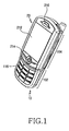
- FIG. 1 illustrates the swing-type portable communication apparatus in the communication mode
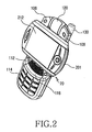
- FIG 2 illustrates the swing-type portable communication apparatus in which the swing housing 20 has been rotated at a right angle so that the display unit 212 is aligned in a widescreen-viewing position.
- the display unit 212 is aligned in the widescreen-viewing position, the user can conveniently use the e-mail, broadcasting, VOD, and game services.
- the second speaker unit preferably generates stereoscopic sound.
- the camera lens assembly 120 is protected by means of the swing housing 20 as shown in FIG. 1.
- the swing housing 20 can automatically, manually, or semi-automatically swing relative to the main housing 10.
- a motor and a reduction module connected to the motor can be used.
- the reduction module includes a gear train capable of reducing the rotational speed of a motor shaft of the motor.
- an elastic member can be used.
- FIG. 2 shows the swing housing 20, which has been rotated counterclockwise at the right angle relative to the main housing 10, the swing housing 20 can rotate clockwise at an angle above 90 degrees relative to the main housing 10.
- the present invention does not limit the structure of the camera lens assembly 120 if the camera lens assembly 120 does not interrupt the swing action of the swing housing 20.
- the camera lens assembly 120 can be fabricated with a flat plate structure as shown in FIGS. 2 and 3.
- the upper end of the main housing 10, in which the support arms 106 and the camera lens assembly 120 are installed has a curvature corresponding to the curvature of the upper end or the lower end 201 of the swing housing 20.
- FIGS. 4 to 7 show a swing-type portable communication apparatus according to a second embodiment of the present invention.
- the swing-type portable communication apparatus according to the second embodiment includes a main housing 30 and a swing housing 40.
- the main housing 30 and the swing housing 40 preferably have plate shapes.
- the swing housing 40 swings within an angle of 180 degrees relative to the main housing 30 while facing the main housing 30, thereby opening/closing an upper surface section of the main housing 30.
- a display unit 412 is aligned in a widescreen-viewing position when the swing housing 40 is in a first position, wherein the swing housing 40 has been rotated at a right angle relative to the main housing 30.
- key arrays 314 and 414a are aligned symmetrically to each other about the display unit 412 when the swing housing 40 is in a second position, wherein the swing housing 40 has been rotated at an angle of 180 degrees relative to the main housing 30, as shown in Fig. 7. If the swing housing 40 is in the second position, the user can conveniently manipulate the key arrays 314 and 414a with both hands.
- FIG. 6 shows the first position of the swing housing 40 and
- FIG. 7 shows the second position of the swing housing 40.
- the upper surface section of the main housing 30 is divided into first and second areas 304 and 302.
- the first area 304 is exposed to an exterior regardless of the swing action of the swing housing 40 and the second area 302 is selectively opened or closed according to the swing action of the swing housing 40.
- the swing housing 40 is provided in the second area 302 of the main housing 30 and swings relative to the second area 302 of the main housing 30.
- the first and the second areas 304 and 302 are aligned in a stepped pattern.
- the second area 302 is positioned downwardly from the first area 304.
- a stepped portion 318 is formed between the first and the second areas 304 and 302.
- the first key array 314 including a plurality of keys is aligned in the first area 304 in such a manner that the first key array 314 can be exposed to the exterior.
- the display unit 412 is provided on an upper surface of the swing housing 40 such that the display unit 412 can also be exposed to the exterior.
- a first speaker unit 410 is installed adjacent to the display unit 412 and a four-way key 414 is positioned below the display unit 412 so that the user can select and execute desired data by using the four-way key 414.
- a camera lens assembly 320 is installed at an upper portion of the second area 302.
- the first key array 314 is positioned in the first area 304.
- keytops 316a having a predetermined thickness are attached to upper surfaces of predetermined keys 316 of the first key array 314.
- four keytops 316a are provided on upper surfaces of four keys 316 aligned in four directions, respectively.
- Numbers or characters are printed on the upper surfaces of the keytops 316. At this time, as shown in FIG. 7, the number or characters are aligned suitable for the widescreen-viewing position of the display unit 412 in order to allow the user to conveniently manipulate the keys with both hands when using the chatting service or the game service.
- the swing housing 40 has an upper end 416 and a lower end 415.
- the lower end 415 of the swing housing 40 has a first curvature and the upper end 416 of the swing housing 40 has a second curvature.
- the stepped portion 318 corresponding to the lower end 415 of the swing housing 40 is formed with a third curvature.
- the first curvature matches with the second curvature.
- the third curvature preferably matches with the first curvature.
- the camera lens assembly 320 is rotatably installed at the upper end portion of the second area 302 of the main housing 30.
- the camera lens assembly 320 is selectively opened or closed by means of the swing housing 40 according to the swing action of the swing housing 40.
- a hinge axis of the camera lens assembly 320 is spaced apart from a swing axis of the swing housing 40 by a predetermined distance and extends perpendicularly to the swing axis of the swing housing 40.
- the camera lens assembly 320 can rotate within an angle of 360 degrees so that a camera lens of the camera lens assembly 320 can be directed towards the second area 302 or the lower side of the main housing 30.
- the camera lens assembly 320 is installed on the upper portion of the second area 104, the present invention does not limit the installation position of the camera lens assembly 320.
- the camera lens assembly 320 can be installed at the upper end or the lower end of the swing housing 40.
- a detachable battery pack 319 is provided at a bottom surface of the main housing 30.
- the battery pack 319 is a rechargeable battery pack, so the user can recharge the battery pack if necessary.
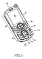
- FIG 4 illustrates the swing-type portable communication apparatus in the communication mode
- FIG. 6 shows the swing-type portable communication apparatus in which the swing housing 40 has been rotated at a right angle so that the display unit 412 is aligned in a widescreen-viewing position.
- the user can conveniently use the e-mail, broadcasting, VOD, and game services.
- the user aligns the display unit 412 in the widescreen-viewing position as shown in FIG. 7 when using the chatting service or the game service.
- the camera lens assembly 320 is protected by means of the swing housing 40 as shown in FIG. 5.
- the swing housing 40 can automatically, manually, or semi-automatically swing relative to the main housing 30.
- a motor and a reduction module connected to the motor can be used.
- an elastic member can be used.
- FIG. 6 shows the swing housing 40, which has been rotated counterclockwise at the right angle relative to the main housing 30, the swing housing 40 can rotate clockwise at an angle of above 90 degrees relative to the main housing 30.
- the present invention does not limit the structure of the camera lens assembly 320 if the camera lens assembly 320 does not interrupt the swing action of the swing housing 40.
- the camera lens assembly 320 can be fabricated with a flat plate structure.
- the user can view the image displayed in the display unit while aligning the display unit in the widescreen-viewing position, so the user can conveniently use the broadcasting and VOD services.
- the user since the user can easily manipulate the keys with one hand or both hands, the user can conveniently use the chatting and game services.
- the camera lens assembly can be protected when the camera lens assembly is not used.
- the swing housing rotates about the swing housing center, i.e., the center point of the swing housing.
Landscapes
- Engineering & Computer Science (AREA)
- Theoretical Computer Science (AREA)
- Computer Hardware Design (AREA)
- Physics & Mathematics (AREA)
- Signal Processing (AREA)
- Human Computer Interaction (AREA)
- General Engineering & Computer Science (AREA)
- General Physics & Mathematics (AREA)
- Mathematical Physics (AREA)
- Telephone Set Structure (AREA)
- Studio Devices (AREA)
Abstract
Description
- The present invention relates to a digital portable communication apparatus, such as a cellular phone, a PDA (personal digital assistant), an HHP (handheld phone), a camera phone, a game phone, or a portable phone having a TV function. More particularly, the present invention relates to a portable communication apparatus suitable for providing users with broadcasting, e-mail, chatting and game services.
- In general, "portable communication apparatuses" refer to electronic appliances that allow users to communication with other users over a wireless network. In consideration of portability, designs of such portable communication apparatuses tend to be compact, slim, and light, while also providing a wider variety of functions including multimedia functionality. Future portable communication apparatuses are expected to incorporate even greater multi-functionality and multi-purpose utilization, as well as being even more compact and light. The portable communication apparatuses will likely be modified for various multimedia environments or Internet environments. Such portable communication apparatuses are now commonly used by all kinds of people including, men and women, the young and old, throughout the world, and are recognized as a nearly indispensable commodity which must be carried always.
- Conventional portable communication apparatuses may be classified into various types according to appearance. For example, portable communication apparatuses are classified into bar-type portable communication apparatuses, flip-type portable communication apparatuses and folder-type portable communication apparatuses. In addition, the portable communication apparatuses can be classified into neck wearable-type and wrist-type portable according to their positions when worn on a human body. Further, the portable communication apparatuses may be classified into rotation-type portable communication apparatuses and sliding-type portable communication apparatuses according to ways of opening and closing the portable communication apparatuses. These variously classified portable communication apparatuses can be easily understood by those skilled in the art.
- Modem portable communication apparatuses transmit data at a high rate in addition to voice communication. In response toconsumer demand, portable communication apparatuses provide consumers with various services by using wireless communication technology capable of high speed data transfer.
- Current design trends include a camera lenses for transmitting an image signal. Current portable communication apparatus models may have internal or external camera lens modules for video, or image communication or to photograph desired subjects.
- Among the conventional portable communication apparatuses, the swing-type portable communication apparatus includes two housings coupled to each other while facing each other in such a manner that one housing can be opened or closed according to the swinging action of the other. Although the conventional swing-type portable communication apparatus has a display unit and a plurality of keys, since it is not equipped with a wide-screen viewing function, the user may feel inconvenienced when viewing the image displayed in the display unit or when manipulating the keys. If the portable communication apparatus is to provide users with various image-communication, game, music, broadcasting, VOD, chatting, and Internet services in various multimedia environments, the user should be able to use the display as a widescreen. Thus, the portable communication apparatus must be suitable for various user-interfacing environments.
- Therefore, it is necessary to set the user interfacing environment of the portable communication apparatus in such a manner that the user can conveniently input/output data into/from the portable communication apparatus. In addition, it is necessary to provide a swing-type portable communication apparatus allowing the user to easily manipulate a display unit and keys thereof.
- Accordingly, the present invention has been made to solve the above-mentioned problems occurring in the prior art, and an object of the present invention is to provide a swing-type portable communication apparatus equipped with a widescreen-viewing function for a display unit.
- Another object of the present invention is to provide a swing-type portable communication apparatus capable of allowing users to conveniently use broadcasting, e-mail, chatting and game services.
- Still another object of the present invention is to provide a swing-type portable communication apparatus capable of protecting a camera lens assembly when the camera lens assembly is not used.
- Still yet another object of the present invention is to provide a swing-type portable communication apparatus equipped with a widescreen-viewingwidescreen-viewing function for a display while allowing users to conveniently manipulate keys with both hands.
- In order to accomplish these objects, according to one aspect of the present invention, there is provided a portable communication apparatus including a main housing having an upper surface divided into a first area including a first key array having a plurality of keys and a second area aligned downwardly from the first area; and a swing housing provided at an upper surface thereof with a display unit and aligned in the second area while facing the second area in order to selectively open or close the second area.
- The above and other objects, features and advantages of the present invention will be more apparent from the following detailed description taken in conjunction with the accompanying drawings, in which:
- FIG. 1 is a perspective view illustrating a swing-type portable communication apparatus in a communication mode according to a first embodiment of the present invention;
- FIG. 2 is a perspective view illustrating the swing-type portable communication apparatus of Fig. 1 in a camera mode, in which a swing housing is rotated at a right angle for a broadcasting service or a VOD services;
- FIG. 3 is a perspective view illustrating a bottom portion of the swing-type portable communication apparatus of FIG 2;
- FIG. 4 is a perspective view illustrating a swing-type portable communication apparatus according to a second embodiment of the present invention;
- FIG. 5 is a perspective view illustrating a bottom portion of the swing-type portable communication apparatus of FIG. 4;
- FIG. 6 is a perspective view of the swing-type portable communication apparatus of Fig. 4 in a camera mode, in which a swing housing is rotated at a right angle for a broadcasting service or a VOD services; and
- FIG. 7 is a perspective view of the swing-type portable communication apparatus of Fig. 4 in a chatting mode or a game mode, in which a swing housing is rotated at an angle of 180 degrees for allowing a user to conveniently manipulate keys with both hands.
-
- Hereinafter, preferred embodiments of the present invention will be described with reference to the accompanying drawings. In the following description of the present invention, a detailed description of known functions and configurations incorporated herein will be omitted when it may make the subject matter of the present invention unclear.
- FIGS. 1 to 3 show a swing-type portable communication apparatus according to a first embodiment of the present invention. The swing-type portable communication apparatus according to the first embodiment of the present invention includes a
main housing 10 and aswing housing 20. Themain housing 10 and theswing housing 20 preferably have plate shapes. The swing housing 20 swings within a predetermined angle relative to themain housing 10 while facing themain housing 10, thereby opening/closing an upper surface section of themain housing 10. - The upper surface section of the
main housing 10 is divided into first andsecond areas first area 102 is exposed regardless of the swing action of theswing housing 20 and thesecond area 104 is selectively opened or closed according to the swing action of theswing housing 20. Theswing housing 20 is provided in thesecond area 104 of themain housing 10 and swings relative to thesecond area 104 of themain housing 10. The first and thesecond areas second area 104 is positioned downwardly from thefirst area 102. Thus, astepped portion 116 is formed between the first and thesecond areas - A
first key array 114 including a plurality of keys is aligned in thefirst area 102 in such a manner that thefirst key array 114 can be exposed to the exterior. Adisplay unit 212 is provided on an upper surface of theswing housing 20 such that thedisplay unit 212 can be exposed to the exterior. Afirst speaker unit 210 is installed adjacent to thedisplay unit 212 and asecond speaker unit 112 is provided in thesecond area 104 in such a manner that thesecond speaker unit 112 can be selectively exposed to the exterior according to the swing action of theswing housing 20. In addition, a four-way key 214 is positioned below thedisplay unit 212 so that the user can select and execute desired data by using the four-way key 214. Thesecond speaker unit 112 is positioned at a lower portion of thesecond area 104 and acamera lens assembly 120 is installed at an upper portion of thesecond area 104. Preferably, thesecond speaker unit 112 generates stereoscopic sound. - The
swing housing 20 has an upper end and alower end 201 formed with a first curvature. Thestepped portion 116 corresponding to thelower end 201 of theswing housing 20 is formed with a second curvature. In order to facilitate the swing action of theswing housing 20, the first curvature matches with the second curvature. In addition, the upper end of theswing housing 20 has a curvature corresponding to the first curvature of the lower end of theswing housing 20, so theswing housing 20 is symmetrically formed about thedisplay unit 212. - As shown in FIG. 2, a pair of
support arms 106 are provided at an upper portion of thesecond area 104 of themain housing 10 and thecamera lens assembly 120 is rotatably aligned between thesupport arms 106. Thecamera lens assembly 120 is selectively opened or closed by means of theswing housing 20 according to the swing action of theswing housing 20. A hinge axis of thecamera lens assembly 120 is spaced apart from a swing axis of theswing housing 20 by a predetermined distance and extends perpendicularly to the swing axis of theswing housing 20. Thecamera lens assembly 120 can rotate within an angle of 360 degrees so that a camera lens of thecamera lens assembly 120 can be directed towards thesecond area 104 or the lower side of themain housing 10. Although it is illustrated that thecamera lens assembly 120 is installed on the upper portion of thesecond area 104, it is also possible to install thecamera lens assembly 120 at the upper end or the lower end of theswing housing 20. - As shown in FIG. 3, a
detachable battery pack 118 is provided at a bottom surface of themain housing 10. Thebattery pack 118 is a rechargeable battery pack, so the user can recharge thebattery pack 118 if necessary. In addition, as shown in FIG. 2, anantenna device 130 is installed at one edge portion of themain body 10. - FIG. 1 illustrates the swing-type portable communication apparatus in the communication mode and FIG 2 illustrates the swing-type portable communication apparatus in which the
swing housing 20 has been rotated at a right angle so that thedisplay unit 212 is aligned in a widescreen-viewing position. If thedisplay unit 212 is aligned in the widescreen-viewing position, the user can conveniently use the e-mail, broadcasting, VOD, and game services. When the user uses the broadcasting service or the game service while aligning thedisplay unit 212 in the widescreen-viewing position as shown in FIG. 2, the second speaker unit preferably generates stereoscopic sound. In addition, when thecamera lens assembly 120 is not used, thecamera lens assembly 120 is protected by means of theswing housing 20 as shown in FIG. 1. - Meanwhile, the
swing housing 20 can automatically, manually, or semi-automatically swing relative to themain housing 10. To allow theswing housing 20 to automatically swing relative to themain housing 10, a motor and a reduction module connected to the motor can be used. The reduction module includes a gear train capable of reducing the rotational speed of a motor shaft of the motor. To allow theswing housing 20 to semi-automatically swing relative to themain housing 10, an elastic member can be used. In addition, although FIG. 2 shows theswing housing 20, which has been rotated counterclockwise at the right angle relative to themain housing 10, theswing housing 20 can rotate clockwise at an angle above 90 degrees relative to themain housing 10. In addition, it is not necessary to fabricate thecamera lens assembly 120 with a cylindrical structure. The present invention does not limit the structure of thecamera lens assembly 120 if thecamera lens assembly 120 does not interrupt the swing action of theswing housing 20. For instance, thecamera lens assembly 120 can be fabricated with a flat plate structure as shown in FIGS. 2 and 3. - Preferably, the upper end of the
main housing 10, in which thesupport arms 106 and thecamera lens assembly 120 are installed, has a curvature corresponding to the curvature of the upper end or thelower end 201 of theswing housing 20. - FIGS. 4 to 7 show a swing-type portable communication apparatus according to a second embodiment of the present invention. The swing-type portable communication apparatus according to the second embodiment includes a
main housing 30 and aswing housing 40. Themain housing 30 and theswing housing 40 preferably have plate shapes. Theswing housing 40 swings within an angle of 180 degrees relative to themain housing 30 while facing themain housing 30, thereby opening/closing an upper surface section of themain housing 30. According to the second embodiment, adisplay unit 412 is aligned in a widescreen-viewing position when theswing housing 40 is in a first position, wherein theswing housing 40 has been rotated at a right angle relative to themain housing 30. - In addition,
key arrays display unit 412 when theswing housing 40 is in a second position, wherein theswing housing 40 has been rotated at an angle of 180 degrees relative to themain housing 30, as shown in Fig. 7. If theswing housing 40 is in the second position, the user can conveniently manipulate thekey arrays swing housing 40 and FIG. 7 shows the second position of theswing housing 40. - The upper surface section of the
main housing 30 is divided into first andsecond areas first area 304 is exposed to an exterior regardless of the swing action of theswing housing 40 and thesecond area 302 is selectively opened or closed according to the swing action of theswing housing 40. Theswing housing 40 is provided in thesecond area 302 of themain housing 30 and swings relative to thesecond area 302 of themain housing 30. The first and thesecond areas second area 302 is positioned downwardly from thefirst area 304. Thus, a steppedportion 318 is formed between the first and thesecond areas - The first
key array 314 including a plurality of keys is aligned in thefirst area 304 in such a manner that the firstkey array 314 can be exposed to the exterior. Thedisplay unit 412 is provided on an upper surface of theswing housing 40 such that thedisplay unit 412 can also be exposed to the exterior. Afirst speaker unit 410 is installed adjacent to thedisplay unit 412 and a four-way key 414 is positioned below thedisplay unit 412 so that the user can select and execute desired data by using the four-way key 414. Acamera lens assembly 320 is installed at an upper portion of thesecond area 302. - The first
key array 314 is positioned in thefirst area 304. As shown in FIGS. 4 and 7, keytops 316a having a predetermined thickness are attached to upper surfaces ofpredetermined keys 316 of the firstkey array 314. Preferably, fourkeytops 316a are provided on upper surfaces of fourkeys 316 aligned in four directions, respectively. Numbers or characters are printed on the upper surfaces of thekeytops 316. At this time, as shown in FIG. 7, the number or characters are aligned suitable for the widescreen-viewing position of thedisplay unit 412 in order to allow the user to conveniently manipulate the keys with both hands when using the chatting service or the game service. - The
swing housing 40 has anupper end 416 and alower end 415. Thelower end 415 of theswing housing 40 has a first curvature and theupper end 416 of theswing housing 40 has a second curvature. In addition, the steppedportion 318 corresponding to thelower end 415 of theswing housing 40 is formed with a third curvature. In order to facilitate the swing action of theswing housing 40, the first curvature matches with the second curvature. In addition, the third curvature preferably matches with the first curvature. - As shown in FIG. 6, the
camera lens assembly 320 is rotatably installed at the upper end portion of thesecond area 302 of themain housing 30. Thecamera lens assembly 320 is selectively opened or closed by means of theswing housing 40 according to the swing action of theswing housing 40. A hinge axis of thecamera lens assembly 320 is spaced apart from a swing axis of theswing housing 40 by a predetermined distance and extends perpendicularly to the swing axis of theswing housing 40. Thecamera lens assembly 320 can rotate within an angle of 360 degrees so that a camera lens of thecamera lens assembly 320 can be directed towards thesecond area 302 or the lower side of themain housing 30. Although it is illustrated that thecamera lens assembly 320 is installed on the upper portion of thesecond area 104, the present invention does not limit the installation position of thecamera lens assembly 320. For instance, thecamera lens assembly 320 can be installed at the upper end or the lower end of theswing housing 40. - As shown in FIG. 5, a
detachable battery pack 319 is provided at a bottom surface of themain housing 30. Thebattery pack 319 is a rechargeable battery pack, so the user can recharge the battery pack if necessary. - FIG 4 illustrates the swing-type portable communication apparatus in the communication mode and FIG. 6 shows the swing-type portable communication apparatus in which the
swing housing 40 has been rotated at a right angle so that thedisplay unit 412 is aligned in a widescreen-viewing position. If thedisplay unit 412 is aligned in the widescreen-viewing position, the user can conveniently use the e-mail, broadcasting, VOD, and game services. Preferably, the user aligns thedisplay unit 412 in the widescreen-viewing position as shown in FIG. 7 when using the chatting service or the game service. In addition, when thecamera lens assembly 320 is not used, thecamera lens assembly 320 is protected by means of theswing housing 40 as shown in FIG. 5. - The
swing housing 40 can automatically, manually, or semi-automatically swing relative to themain housing 30. To allow theswing housing 40 to automatically swing relative to themain housing 30, a motor and a reduction module connected to the motor can be used. In order to allow theswing housing 40 to semi-automatically swing relative to themain housing 30, an elastic member can be used. In addition, although FIG. 6 shows theswing housing 40, which has been rotated counterclockwise at the right angle relative to themain housing 30, theswing housing 40 can rotate clockwise at an angle of above 90 degrees relative to themain housing 30. In addition, it is not necessary to fabricate thecamera lens assembly 320 with a cylindrical structure. The present invention does not limit the structure of thecamera lens assembly 320 if thecamera lens assembly 320 does not interrupt the swing action of theswing housing 40. For instance, thecamera lens assembly 320 can be fabricated with a flat plate structure. - As described above, according to the present invention, the user can view the image displayed in the display unit while aligning the display unit in the widescreen-viewing position, so the user can conveniently use the broadcasting and VOD services. In particular, since the user can easily manipulate the keys with one hand or both hands, the user can conveniently use the chatting and game services. In addition, the camera lens assembly can be protected when the camera lens assembly is not used. In each embodiment, the swing housing rotates about the swing housing center, i.e., the center point of the swing housing.
- While the invention has been shown and described with reference to certain preferred embodiments thereof, it will be understood by those skilled in the art that various changes in form and details may be made therein without departing from the scope of the invention as defined by the appended claims.
Claims (15)
- A portable communication apparatus comprising:a main housing (10, 30) having an upper surface divided into a first area (102, 304) including a first key array (114, 314) having a plurality of keys and a second area (104, 302) aligned adjacent to the first area (102, 304); anda swing housing (20, 40) provided at an upper surface thereof with a display unit (212, 412) and aligned in the second area (104, 302) while facing the second area in order to selectively open or close the second area.
- The portable communication apparatus as claimed in claim 1, wherein a stepped portion (116, 312) is formed between the first and second areas such that the first area (102, 304) is stepped downward from the second area (104, 302).
- The portable communication apparatus according to claim 1 or 2, wherein the display unit (212, 412) is aligned in a widescreen-viewing position in a first position of the swing housing (20, 40) and first and second key arrays (114, 314) are aligned at both sides of the display unit in a second position of the swing housing.
- The portable communication apparatus as claimed in one of the previous claims, wherein a lower end (201, 415) of the swing housing (20, 40) has a first curvature, and said stepped portion (116, 318) formed between the first and second areas of the main housing has a second curvature corresponding to the first curvature.
- The portable communication apparatus as claimed in one of the previous claims, wherein the swing housing has a first speaker unit (210) aligned adjacent to the display unit (212), and the second area (104) has a second speaker unit (112) which is selectively opened or closed according to swing action of the swing housing.
- The portable communication apparatus as claimed in one of the previous claims, wherein the swing housing (20, 40) has a four-way key (214, 414) aligned adjacent to the display unit (212, 412).
- The portable communication apparatus as claimed in one of the previous claims, wherein a pair of support arms (106) are provided at an upper end portion of the main housing (20) and a camera lens assembly (120, 320) is rotatably installed between the support arms in such a manner that the camera lens assembly is directed towards a lower portion of the main housing.
- The portable communication apparatus as claimed in claim 7, wherein the camera lens assembly (120, 320) is rotatably installed and selectively opened or closed by means of the swing housing according to swing action of the swing housing.
- The portable communication apparatus as claimed in one of the previous claims, wherein the swing housing (212, 412) is symmetrically formed about the display unit.
- The portable communication apparatus as claimed in one of the previous claims, wherein the swing housing (20, 40) forms a cross together with the main housing when the swing housing rotates at a right angle relative to the main housing (10, 30).
- The portable communication apparatus as claimed in one of the previous claims, wherein the swing housing (20, 40) has been rotated at a right angle in the first position, and the swing housing has been rotated at an angle of 180 degrees in the second position.
- The portable communication apparatus as claimed in one of the previous claims, wherein an upper end (416) of the swing housing (40) has a first curvature and a lower end (415) of the swing housing has a second curvature corresponding to the first curvature.
- The portable communication apparatus as claimed in one of the previous claims, further comprising keytops (316a) having a predetermined thickness and being attached to upper surfaces of keys (316) selected from the first key array (314).
- The portable communication apparatus as claimed in claim 13, wherein the keytops (316a) are provided on upper surfaces of four keys (316) aligned in four directions, respectively, numbers or characters are printed on upper surfaces of the keytops, and the numbers or characters are aligned suitable for a widescreen-viewing position of the display unit.
- The portable communication apparatus as claimed in claim 1, wherein said second area (104, 302) is stepped with respect to the first area (102, 304).
Priority Applications (1)
| Application Number | Priority Date | Filing Date | Title |
|---|---|---|---|
| EP08016645.7A EP2007115B1 (en) | 2004-05-06 | 2005-05-06 | Swing-type portable communication apparatus |
Applications Claiming Priority (6)
| Application Number | Priority Date | Filing Date | Title |
|---|---|---|---|
| US56897004P | 2004-05-06 | 2004-05-06 | |
| US568970P | 2004-05-06 | ||
| US62256404P | 2004-10-26 | 2004-10-26 | |
| US622564P | 2004-10-26 | ||
| KR2005028254 | 2005-04-04 | ||
| KR1020050028254A KR100703351B1 (en) | 2004-05-06 | 2005-04-04 | Swing type mobile device |
Related Child Applications (1)
| Application Number | Title | Priority Date | Filing Date |
|---|---|---|---|
| EP08016645.7A Division EP2007115B1 (en) | 2004-05-06 | 2005-05-06 | Swing-type portable communication apparatus |
Publications (1)
| Publication Number | Publication Date |
|---|---|
| EP1594292A1 true EP1594292A1 (en) | 2005-11-09 |
Family
ID=37149343
Family Applications (2)
| Application Number | Title | Priority Date | Filing Date |
|---|---|---|---|
| EP05009981A Withdrawn EP1594292A1 (en) | 2004-05-06 | 2005-05-06 | Swing-type portable communication apparatus |
| EP08016645.7A Expired - Lifetime EP2007115B1 (en) | 2004-05-06 | 2005-05-06 | Swing-type portable communication apparatus |
Family Applications After (1)
| Application Number | Title | Priority Date | Filing Date |
|---|---|---|---|
| EP08016645.7A Expired - Lifetime EP2007115B1 (en) | 2004-05-06 | 2005-05-06 | Swing-type portable communication apparatus |
Country Status (4)
| Country | Link |
|---|---|
| US (1) | US7580734B2 (en) |
| EP (2) | EP1594292A1 (en) |
| KR (1) | KR100703351B1 (en) |
| CN (1) | CN1697461A (en) |
Cited By (2)
| Publication number | Priority date | Publication date | Assignee | Title |
|---|---|---|---|---|
| EP1710987A1 (en) | 2005-04-06 | 2006-10-11 | Samsung Electronics Co., Ltd. | Swing hinge device for mobile terminal |
| EP1793567A3 (en) * | 2005-11-30 | 2007-08-08 | Sony Ericsson Mobile Communications Japan, Inc. | Rotatable mobile information terminal with several operation modes and method of controlling the same |
Families Citing this family (38)
| Publication number | Priority date | Publication date | Assignee | Title |
|---|---|---|---|---|
| KR100598062B1 (en) * | 2004-04-14 | 2006-07-10 | 주식회사 팬택앤큐리텔 | How to send / receive data with the cover closed |
| US7280857B2 (en) * | 2004-06-25 | 2007-10-09 | Nokia Corporation | Mobile communications device having rotating display and camera |
| WO2006038554A1 (en) * | 2004-10-01 | 2006-04-13 | Sharp Kabushiki Kaisha | Mobile information terminal |
| USD523836S1 (en) * | 2004-10-13 | 2006-06-27 | Lg Electronics Inc. | Cellular phone |
| USD523837S1 (en) * | 2004-10-28 | 2006-06-27 | Lg Electronics Inc. | Phone-combined personal digital assistant |
| USD523834S1 (en) * | 2004-11-11 | 2006-06-27 | Fih Co., Ltd. | Mobile phone |
| USD525228S1 (en) * | 2005-01-19 | 2006-07-18 | Samsung Electronics Co., Ltd. | Cellular phone |
| USD542758S1 (en) * | 2005-01-26 | 2007-05-15 | Samsung Electronics Co., Ltd. | Portable phone |
| USD530697S1 (en) * | 2005-02-09 | 2006-10-24 | Motorola, Inc. | Radio telephone |
| USD551638S1 (en) | 2005-02-11 | 2007-09-25 | Motorola, Inc. | Wireless communication device |
| USD540293S1 (en) * | 2005-04-06 | 2007-04-10 | Samsung Electronics Co., Ltd. | Portable phone |
| USD541782S1 (en) * | 2005-06-20 | 2007-05-01 | Samsung Electronics Co., Ltd. | Mobile phone |
| USD542762S1 (en) * | 2005-06-24 | 2007-05-15 | Samsung Electronics Co., Ltd. | Mobile phone |
| KR100734631B1 (en) * | 2005-08-16 | 2007-07-02 | 주식회사 팬택 | Hinge module of swing type mobile communication terminal |
| ES2449515T3 (en) * | 2005-10-06 | 2014-03-20 | Henkel Ag & Co. Kgaa | Vibration transfer reduction |
| US20070094612A1 (en) * | 2005-10-24 | 2007-04-26 | Nokia Corporation | Method, a device and a computer program product for dynamically positioning of a pop-up window |
| USD560635S1 (en) * | 2005-11-14 | 2008-01-29 | Samsung Electronics Co., Ltd. | Mobile phone |
| KR100683868B1 (en) * | 2005-12-05 | 2007-02-15 | 삼성전자주식회사 | Antenna applied to slide type mobile communication terminal |
| USD543179S1 (en) * | 2005-12-27 | 2007-05-22 | Motorola Inc. | Communication device |
| USD556207S1 (en) * | 2006-02-13 | 2007-11-27 | Research In Motion Limited | Keyboard of a hand-held electronic device |
| US8000741B2 (en) * | 2006-02-13 | 2011-08-16 | Research In Motion Limited | Handheld wireless communication device with chamfer keys |
| USD555142S1 (en) * | 2006-03-17 | 2007-11-13 | Samsung Electronics Co., Ltd. | Portable phone |
| USD586344S1 (en) | 2006-06-20 | 2009-02-10 | Research In Motion Limited | Hand-held electronic device |
| USD587705S1 (en) | 2006-06-20 | 2009-03-03 | Research In Motion Limited | Hand-held electronic device |
| EP1887762A2 (en) * | 2006-08-08 | 2008-02-13 | Samsung Electronics Co., Ltd. | Portable terminal having game function |
| KR100819241B1 (en) * | 2006-11-23 | 2008-04-02 | 삼성전자주식회사 | Keypad of a mobile terminal |
| JP4416804B2 (en) | 2007-03-26 | 2010-02-17 | シャープ株式会社 | Mobile device |
| EP2144423A4 (en) * | 2007-04-25 | 2012-05-16 | Nec Corp | Rotation type portable terminal |
| USD620917S1 (en) * | 2007-12-26 | 2010-08-03 | Aiphone Co., Ltd. | Interphone |
| EP2337314B1 (en) * | 2008-10-10 | 2015-10-07 | NEC Corporation | Mobile terminal, mobile terminal control method, and recording medium |
| JP5218212B2 (en) * | 2009-03-30 | 2013-06-26 | 富士通株式会社 | Information terminal equipment |
| US8630089B2 (en) | 2011-01-21 | 2014-01-14 | Blackberry Limited | Resilient swivel coupling mechanism |
| US8498102B2 (en) | 2011-03-04 | 2013-07-30 | Research In Motion Limited | Rotatable coupling mechanism |
| US8471820B2 (en) | 2011-03-28 | 2013-06-25 | Research In Motion Limited | Pivotable display guide mechanism for an electronic mobile device |
| US8693188B2 (en) | 2011-05-24 | 2014-04-08 | Blackberry Limited | Pivotable display guide mechanism for an electronic mobile device |
| CN208063255U (en) | 2018-02-09 | 2018-11-06 | 广东欧珀移动通信有限公司 | Mobile terminal |
| KR20210058556A (en) * | 2019-11-14 | 2021-05-24 | 삼성전자주식회사 | Foldable electronic device |
| CN112532841A (en) * | 2020-11-26 | 2021-03-19 | 深圳卡多希科技有限公司 | Live broadcast equipment |
Citations (7)
| Publication number | Priority date | Publication date | Assignee | Title |
|---|---|---|---|---|
| JPH09261312A (en) * | 1996-03-19 | 1997-10-03 | Fujitsu Ltd | Mobile phone |
| JP2000278659A (en) * | 1999-03-25 | 2000-10-06 | Sony Corp | Portable communication device and communication method thereof |
| JP2002057771A (en) * | 2000-08-08 | 2002-02-22 | Alps Electric Co Ltd | Personal digital assistant |
| WO2003019911A1 (en) * | 2001-07-19 | 2003-03-06 | Zhanxin Zhu | A kind of mobile telephone having rotation display screen |
| US20030087609A1 (en) * | 2001-11-05 | 2003-05-08 | Yung-Fa Cheng | Mobile phone with a hidden input device |
| EP1357726A1 (en) * | 2002-04-26 | 2003-10-29 | Nec Corporation | Portable telephone having a rotating display and two cameras |
| EP1542433A1 (en) * | 2003-12-09 | 2005-06-15 | Lg Electronics Inc. | Portable terminal with position-variable display and method |
Family Cites Families (11)
| Publication number | Priority date | Publication date | Assignee | Title |
|---|---|---|---|---|
| KR100539527B1 (en) * | 2001-06-12 | 2005-12-29 | 엘지전자 주식회사 | Portable Telephone with Camera |
| KR100470172B1 (en) * | 2001-06-22 | 2005-02-04 | 주식회사 임팩트라 | Mobile Station having Display Part Convertible Vertical into Horizontal |
| KR100442598B1 (en) * | 2001-09-06 | 2004-08-02 | 삼성전자주식회사 | Rotational lens housing mounting device and folder-type telephone therewith |
| KR100486611B1 (en) * | 2001-12-18 | 2005-05-03 | 주식회사 팬택앤큐리텔 | A personal mobile telephone haivng a LCD apparatus being capable of rotating |
| KR100810300B1 (en) * | 2002-10-15 | 2008-03-06 | 삼성전자주식회사 | Portable communication device |
| US8019388B2 (en) * | 2003-02-06 | 2011-09-13 | Flextronics Ap, Llc | Main menu navigation principle for mobile phone user |
| KR20040091272A (en) * | 2003-04-21 | 2004-10-28 | 홍충식 | Double folder mobile phone |
| US7149557B2 (en) * | 2003-05-12 | 2006-12-12 | Siemens Communications, Inc. | Mobile communication device having extendable display |
| US7050767B2 (en) * | 2003-07-07 | 2006-05-23 | Sony Ericsson Mobile Communications, Ab | Mobile computing devices having rotationally exposed user interface devices |
| US7162030B2 (en) * | 2003-12-23 | 2007-01-09 | Nokia Corporation | Communication device with rotating housing |
| KR100637580B1 (en) * | 2004-04-16 | 2006-10-20 | 주식회사 팬택앤큐리텔 | Mobile communication terminal with rotating display screen |
-
2005
- 2005-04-04 KR KR1020050028254A patent/KR100703351B1/en not_active Expired - Fee Related
- 2005-05-06 EP EP05009981A patent/EP1594292A1/en not_active Withdrawn
- 2005-05-06 US US11/123,319 patent/US7580734B2/en not_active Expired - Fee Related
- 2005-05-06 EP EP08016645.7A patent/EP2007115B1/en not_active Expired - Lifetime
- 2005-05-08 CN CNA200510068331XA patent/CN1697461A/en active Pending
Patent Citations (7)
| Publication number | Priority date | Publication date | Assignee | Title |
|---|---|---|---|---|
| JPH09261312A (en) * | 1996-03-19 | 1997-10-03 | Fujitsu Ltd | Mobile phone |
| JP2000278659A (en) * | 1999-03-25 | 2000-10-06 | Sony Corp | Portable communication device and communication method thereof |
| JP2002057771A (en) * | 2000-08-08 | 2002-02-22 | Alps Electric Co Ltd | Personal digital assistant |
| WO2003019911A1 (en) * | 2001-07-19 | 2003-03-06 | Zhanxin Zhu | A kind of mobile telephone having rotation display screen |
| US20030087609A1 (en) * | 2001-11-05 | 2003-05-08 | Yung-Fa Cheng | Mobile phone with a hidden input device |
| EP1357726A1 (en) * | 2002-04-26 | 2003-10-29 | Nec Corporation | Portable telephone having a rotating display and two cameras |
| EP1542433A1 (en) * | 2003-12-09 | 2005-06-15 | Lg Electronics Inc. | Portable terminal with position-variable display and method |
Non-Patent Citations (2)
| Title |
|---|
| PATENT ABSTRACTS OF JAPAN vol. 2000, no. 13 5 February 2001 (2001-02-05) * |
| PATENT ABSTRACTS OF JAPAN vol. 2002, no. 06 4 June 2002 (2002-06-04) * |
Cited By (3)
| Publication number | Priority date | Publication date | Assignee | Title |
|---|---|---|---|---|
| EP1710987A1 (en) | 2005-04-06 | 2006-10-11 | Samsung Electronics Co., Ltd. | Swing hinge device for mobile terminal |
| US7865151B2 (en) | 2005-04-06 | 2011-01-04 | Samsung Electronics Co., Ltd | Swing hinge device for mobile terminal |
| EP1793567A3 (en) * | 2005-11-30 | 2007-08-08 | Sony Ericsson Mobile Communications Japan, Inc. | Rotatable mobile information terminal with several operation modes and method of controlling the same |
Also Published As
| Publication number | Publication date |
|---|---|
| US20050266898A1 (en) | 2005-12-01 |
| KR20060045505A (en) | 2006-05-17 |
| US7580734B2 (en) | 2009-08-25 |
| KR100703351B1 (en) | 2007-04-03 |
| EP2007115B1 (en) | 2013-05-01 |
| CN1697461A (en) | 2005-11-16 |
| EP2007115A1 (en) | 2008-12-24 |
Similar Documents
| Publication | Publication Date | Title |
|---|---|---|
| EP2007115B1 (en) | Swing-type portable communication apparatus | |
| EP1610530B1 (en) | Dual-axis rotation folder-type portable apparatus | |
| US7373187B2 (en) | Portable digital communication apparatus having sliding/rotational hinge means | |
| US7587225B2 (en) | Sliding-folding type portable communication apparatus | |
| US7353050B2 (en) | Portable digital communication apparatus with reversible dual-axis hinge | |
| US7092747B2 (en) | Sliding/swing-type portable digital communication apparatus | |
| EP1657889A1 (en) | Portable communication apparatus with triangular prism structure | |
| US7522944B2 (en) | Portable communication apparatus | |
| EP1475943A1 (en) | Portable communication apparatus having improved capability in inputting data | |
| EP1538814A1 (en) | Sliding/folding-type portable digital communication apparatus | |
| US7711397B2 (en) | Portable communication terminal for games and user interfacing device thereof | |
| CN100583659C (en) | portable communication device | |
| EP1653713A2 (en) | Portable and foldable communication terminal | |
| KR100842530B1 (en) | Portable electronic devices | |
| US7440784B2 (en) | Portable communication apparatus | |
| KR100703509B1 (en) | Sliding handheld mobile game console | |
| KR100575935B1 (en) | Biaxial Rotating Handheld Terminal | |
| CN100525328C (en) | Portable terminal with slide keypad for convenient data input | |
| EP1594291A1 (en) | Sliding/folding-type portable apparatus | |
| CN100484153C (en) | Screen rotating device of mobile terminal | |
| KR100703449B1 (en) | Folding sliding type portable terminal for multimedia | |
| KR101155250B1 (en) | Mobile devices | |
| KR20070003347A (en) | Swing type mobile device for easy camera shooting |
Legal Events
| Date | Code | Title | Description |
|---|---|---|---|
| PUAI | Public reference made under article 153(3) epc to a published international application that has entered the european phase |
Free format text: ORIGINAL CODE: 0009012 |
|
| 17P | Request for examination filed |
Effective date: 20050506 |
|
| AK | Designated contracting states |
Kind code of ref document: A1 Designated state(s): AT BE BG CH CY CZ DE DK EE ES FI FR GB GR HU IE IS IT LI LT LU MC NL PL PT RO SE SI SK TR |
|
| AX | Request for extension of the european patent |
Extension state: AL BA HR LV MK YU |
|
| AKX | Designation fees paid |
Designated state(s): DE FR GB |
|
| 17Q | First examination report despatched |
Effective date: 20071009 |
|
| RAP1 | Party data changed (applicant data changed or rights of an application transferred) |
Owner name: SAMSUNG ELECTRONICS CO., LTD. |
|
| STAA | Information on the status of an ep patent application or granted ep patent |
Free format text: STATUS: THE APPLICATION IS DEEMED TO BE WITHDRAWN |
|
| 18D | Application deemed to be withdrawn |
Effective date: 20130213 |