EP1594241A1 - Optical communication network system - Google Patents
Optical communication network system Download PDFInfo
- Publication number
- EP1594241A1 EP1594241A1 EP04711045A EP04711045A EP1594241A1 EP 1594241 A1 EP1594241 A1 EP 1594241A1 EP 04711045 A EP04711045 A EP 04711045A EP 04711045 A EP04711045 A EP 04711045A EP 1594241 A1 EP1594241 A1 EP 1594241A1
- Authority
- EP
- European Patent Office
- Prior art keywords
- network
- optical
- wavelength
- node
- equipment
- Prior art date
- Legal status (The legal status is an assumption and is not a legal conclusion. Google has not performed a legal analysis and makes no representation as to the accuracy of the status listed.)
- Granted
Links
Images















































Classifications
-
- H—ELECTRICITY
- H04—ELECTRIC COMMUNICATION TECHNIQUE
- H04Q—SELECTING
- H04Q11/00—Selecting arrangements for multiplex systems
- H04Q11/0001—Selecting arrangements for multiplex systems using optical switching
- H04Q11/0062—Network aspects
-
- H—ELECTRICITY
- H04—ELECTRIC COMMUNICATION TECHNIQUE
- H04J—MULTIPLEX COMMUNICATION
- H04J14/00—Optical multiplex systems
- H04J14/02—Wavelength-division multiplex systems
- H04J14/0227—Operation, administration, maintenance or provisioning [OAMP] of WDM networks, e.g. media access, routing or wavelength allocation
-
- H—ELECTRICITY
- H04—ELECTRIC COMMUNICATION TECHNIQUE
- H04J—MULTIPLEX COMMUNICATION
- H04J14/00—Optical multiplex systems
- H04J14/02—Wavelength-division multiplex systems
- H04J14/0227—Operation, administration, maintenance or provisioning [OAMP] of WDM networks, e.g. media access, routing or wavelength allocation
- H04J14/0228—Wavelength allocation for communications one-to-all, e.g. broadcasting wavelengths
-
- H—ELECTRICITY
- H04—ELECTRIC COMMUNICATION TECHNIQUE
- H04J—MULTIPLEX COMMUNICATION
- H04J14/00—Optical multiplex systems
- H04J14/02—Wavelength-division multiplex systems
- H04J14/0227—Operation, administration, maintenance or provisioning [OAMP] of WDM networks, e.g. media access, routing or wavelength allocation
- H04J14/0241—Wavelength allocation for communications one-to-one, e.g. unicasting wavelengths
-
- H—ELECTRICITY
- H04—ELECTRIC COMMUNICATION TECHNIQUE
- H04J—MULTIPLEX COMMUNICATION
- H04J14/00—Optical multiplex systems
- H04J14/02—Wavelength-division multiplex systems
- H04J14/0278—WDM optical network architectures
- H04J14/0282—WDM tree architectures
-
- H—ELECTRICITY
- H04—ELECTRIC COMMUNICATION TECHNIQUE
- H04J—MULTIPLEX COMMUNICATION
- H04J14/00—Optical multiplex systems
- H04J14/02—Wavelength-division multiplex systems
- H04J14/0278—WDM optical network architectures
- H04J14/0283—WDM ring architectures
-
- H—ELECTRICITY
- H04—ELECTRIC COMMUNICATION TECHNIQUE
- H04J—MULTIPLEX COMMUNICATION
- H04J14/00—Optical multiplex systems
- H04J14/02—Wavelength-division multiplex systems
- H04J14/0278—WDM optical network architectures
- H04J14/0284—WDM mesh architectures
-
- H—ELECTRICITY
- H04—ELECTRIC COMMUNICATION TECHNIQUE
- H04L—TRANSMISSION OF DIGITAL INFORMATION, e.g. TELEGRAPHIC COMMUNICATION
- H04L41/00—Arrangements for maintenance, administration or management of data switching networks, e.g. of packet switching networks
- H04L41/12—Discovery or management of network topologies
-
- H—ELECTRICITY
- H04—ELECTRIC COMMUNICATION TECHNIQUE
- H04L—TRANSMISSION OF DIGITAL INFORMATION, e.g. TELEGRAPHIC COMMUNICATION
- H04L41/00—Arrangements for maintenance, administration or management of data switching networks, e.g. of packet switching networks
- H04L41/34—Signalling channels for network management communication
-
- H—ELECTRICITY
- H04—ELECTRIC COMMUNICATION TECHNIQUE
- H04Q—SELECTING
- H04Q11/00—Selecting arrangements for multiplex systems
- H04Q11/0001—Selecting arrangements for multiplex systems using optical switching
- H04Q11/0005—Switch and router aspects
- H04Q2011/0007—Construction
- H04Q2011/0011—Construction using wavelength conversion
-
- H—ELECTRICITY
- H04—ELECTRIC COMMUNICATION TECHNIQUE
- H04Q—SELECTING
- H04Q11/00—Selecting arrangements for multiplex systems
- H04Q11/0001—Selecting arrangements for multiplex systems using optical switching
- H04Q11/0005—Switch and router aspects
- H04Q2011/0007—Construction
- H04Q2011/0032—Construction using static wavelength routers (e.g. arrayed waveguide grating router [AWGR] )
-
- H—ELECTRICITY
- H04—ELECTRIC COMMUNICATION TECHNIQUE
- H04Q—SELECTING
- H04Q11/00—Selecting arrangements for multiplex systems
- H04Q11/0001—Selecting arrangements for multiplex systems using optical switching
- H04Q11/0062—Network aspects
- H04Q2011/0073—Provisions for forwarding or routing, e.g. lookup tables
-
- H—ELECTRICITY
- H04—ELECTRIC COMMUNICATION TECHNIQUE
- H04Q—SELECTING
- H04Q11/00—Selecting arrangements for multiplex systems
- H04Q11/0001—Selecting arrangements for multiplex systems using optical switching
- H04Q11/0062—Network aspects
- H04Q2011/009—Topology aspects
Definitions
- the present invention relates to a fiber optic communication system, a wavelength tunable light source unit thereof, a network-node equipment having a wavelength tunable optical receiver unit installed, and a central processing unit and a computer program thereof, that are applied to a geographically-distributed iDC (Internet Data Center) implemented for a local administrative network, and to an IX (Internet exchange) network, and in which, by changing the wavelengths of optical signals used for the connection between network-node equipments, the logical network topology can be easily reconfigured on M network-node equipments (M is an integer no smaller than 2, nor greater than M) that are connected to a uniform-loss and cyclic-frequency (ULCF) arrayed wavelength grating (AWG) having N inputs and N outputs (N is an integer greater than or equal to 2).
- M network-node equipments
- ULCF uniform-loss and cyclic-frequency arrayed wavelength grating
- a fiber optic communication system has been expected in which connections with any network-node can be selectively established and logical network topologies can be arbitrarily reconfigured, by changing the wavelength of optical signals used for the connection between network nodes, by a wavelength tunable light source unit and a wavelength tunable optical receiver unit installed on network-node equipments in a fiber optic communication network that is physically connected to a uniform-loss and cyclic-frequency (ULCF) arrayed wavelength grating (AWG) in a star-shape via an optical wave guide such as an optical fiber (see also: K.
- ULCF uniform-loss and cyclic-frequency
- AWG arrayed wavelength grating
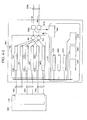
- An optical splitter (4-1) is one which splits an input optical signal into two regardless of its wavelength.
- An optical signal having eight wavelengths which is transmitted through the optical fiber is input thereto, and signals are output to an optical filter 4-2, a fixed-wavelength receiver unit A (4-4), and a fixed-wavelength receiver unit B (4-11).
- the optical filter 4-2 has a function of intercepting from among the optical signals of eight wavelengths outputted from the optical splitter 4-1, two wavelengths, ⁇ s (short wavelength) and ⁇ e (long wavelength) that the network terminal transmits and receives, and transmitting the other wavelengths.
- An optical combiner 4-3 combines the optical signals of six wavelengths transmitted from the optical filter 4-2 and optical signals of two wavelengths ( ⁇ s, ⁇ e) outputted from a wavelength tunable transponder unit A (4-7) and a wavelength tunable transponder unit B 14, and transmits them to optical fibers (not shown).
- the optical signals transmitted are inputted to the optical splitter 1 of the neighboring network-node equipment via an optical fiber (not shown in the diagram).
- the fixed-wavelength receiver unit A (4-4) comprises a fixed-wavelength optical filter and a photodetector, and has a function of receiving only the optical signal of wavelength ⁇ s from among the optical signals of two wavelengths ( ⁇ s, ⁇ e) outputted from the optical splitter 4-1, and converting the signal into an electrical signal.
- the fixed-wavelength receiver unit B (4-11) receives only the optical signal of wavelength ⁇ e, and converts it into an electrical signal.
- Selectors A and B respectively reference received destination information assigned to the received data, and output the received data to a data processing module if the received data is addressed to the own network-node equipment. Also, if the received data is not addressed to the own network-node equipment and is to be relayed, the received data is outputted to a predetermined dual port memory of memory units A and B according to the received destination information.
- Memory units A and B (4-6 and 4-13) have two dual port memories for data that specifies the wavelength of launched optical signal for every wavelength of launched optical signal, and one dual port memory for the data that does not specify the wavelength of launched optical signal.
- the wavelength tunable transponder units A and B (4-7 and 4-14) have a function to convert the transmitted data into an optical signal and transmit it with two respective wavelengths: wavelength ⁇ s and wavelength ⁇ e.
- the wavelength tunable transponder unit A (4-7) is paired with the fixed-wavelength receiver unit A
- the wavelength tunable transponder unit 4-14 is paired with the fixed-wavelength receiver unit B (4-11).
- a data processing module 4-8 of the network-node equipment performs the requested process for the data transmitted from other network-node equipment while performing processes such as assigning received destination information for the data that is to be transmitted from the own network-node equipment to another network-node equipment, and outputs the data to the memory unit A (4-6) or the memory unit B (4-13).
- An end of transmission detection unit 4-9 detects the transmission end of the data stored in each of the dual port memories of the memory unit A (4-6) and the memory unit B (4-13), and outputs a wavelength switch signal to a wavelength controlling unit 4-10.
- the wavelength controlling unit 4-10 controls the oscillating wavelengths used for the wavelength tunable transponder units A and B to be ⁇ s and ⁇ e, by regulating the injection current of a tunable laser diode (hereunder referred to as TLD), which is described later.
- TLD tunable laser diode
- VLAN virtual LAN
- the installation of a new network-node equipment or removal of network-node equipment, and in the reconfiguration of a logical network topology in order to circumvent failure there is complexity in each of the various kinds of settings, and a few months to six months is required for the construction. Also these operations have required a lot of work and there has been the problem of the risk of network collapse and so forth caused by human error.
- a network-node equipment autonomously performs controls related to search and determination of the wavelength of optical signals used for connection with other network-node equipments.
- the two wavelengths to be used are not regulated to be just two successive adjacent wavelengths, and when the case of connections with many network-node equipments using more than two wavelengths is considered, there is concern of an increase in processing time required for the data processing module in the network-node equipment shown in FIG. 4-34.
- topology reconfiguration needs to be performed promptly according to changes in traffic pattern or efficient network usage, and in terms of stable network operation it is preferable not to require a long time from the start of the topology reconfiguration to its completion, and it has been desirable that high-speed topology reconfiguration be made possible.
- a logical topology reconfigurable optical network system a central-management-equipment, and a wavelength tunable light source unit thereof, and a network-node equipment into which is installed a wavelength tunable optical receiver unit and a computer program thereof, which are applicable to a geographically-distributed iDC (Internet Data Center) implemented for a local administrative network and to an IX (Internet exchange) network, and in which, installation and utilization of the logical topology reconfigurable optical network system, which is realized with a wavelength path routing function of an arrayed waveguide grating (AWG) and wavelength tunable light sources mounted on network-node equipments that are physically connected to the AWG in a star shape via optical waveguides such as optical fibers, can be achieved.
- AWG arrayed waveguide grating
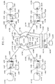
- a fiber optic communication system comprising an arrayed waveguide grating (AWG) that has N optical input ports (where N is an integer greater than or equal to 2) and N optical output ports, and that has a routing function that outputs to predetermined optical output ports in accordance with a wavelength of optical signals inputted to respective optical input ports, and M (where M is an integer no smaller than 2, nor greater than an integer N) network-node equipments connected via optical transmission paths so as to form a geometrically star-shaped physical star topology having the AWG in the center, wherein the network-node equipments comprise a device of wavelength switching that switches the wavelength of the optical signals in order to dynamically change a logical network topology that indicates a geometrical form of routes of the optical signals used for transmitting/receiving data (hereunder referred to as optical signals) between network-node equipments.
- AWG arrayed waveguide grating
- the network-node equipments belong to at least one or more logical network topologies, and configure two or more mutually independent logical network topologies.
- the device of wavelength switching switches wavelengths of optical signals when connecting or transferring the network-node equipments belonging to a predetermined logical network topology, to another logical network topology.
- a logical network topology is configured with two or more network-node equipments, and the device of wavelength switching switches wavelengths of optical signals so that at a predetermined time, all of the two or more network-node equipments configure a new logical network topology that is different from the logical network topology.
- the logical network topology configures at least one kind of either: a ring-shaped logical network topology having geometrically a ring shape, a star-shaped logical network topology having a star shape, and a mesh-shaped logical network topology having a mesh shape, or configures a logical network topology that is a combination of these.
- the device of wavelength switching comprises a wavelength tunable light source unit capable of changing the wavelength of an output signal, and a wavelength tunable optical receiver unit capable of selecting the wavelength of a receiving optical signal; and the wavelength tunable light source unit comprises L (L being an integer no smaller than 2, nor greater than M) optical elements installed therein, the optical elements comprising an elemental structure in which a wavelength tunable laser and a modulator are connected in series or mutually integrated, or comprising a semiconductor laser diode with direct modulation capability, and being connected by an Lx1 optical coupler; and the wavelength tunable optical receiver unit comprises L (L being an integer no smaller than 2, nor greater than M) optical elements installed therein, said optical elements comprising an optical receiver and a wavelength tunable filter connected in series with the optical receiver and passing only a predetermined wavelength, and being connected to an Lx1 optical coupler.
- L being an integer no smaller than 2, nor greater than M
- the device of wavelength switching comprises a wavelength tunable light source unit capable of changing the wavelength of an output signal, and a wavelength tunable optical receiver unit capable of selecting the wavelength of a receiving optical signal; and the wavelength tunable light source unit comprises L (L being an integer no smaller than 2, nor greater than M) optical elements installed therein, the optical elements comprising an elemental structure in which a wavelength tunable laser and a modulator are connected in series or mutually integrated, or comprising a semiconductor laser diode with direct modulation capability, and being connected in series to LxN switches and Nx1 combiners which are connected in series, and the wavelength tunable optical receiver unit comprises L (L is an integer no smaller than 2, nor greater than M) optical receivers installed therein, the optical receivers being connected in series to the LxN switches and the Nx1 combiners.
- L being an integer no smaller than 2, nor greater than M
- the network-node equipment comprises: L (L is an integer no smaller than 2, nor greater than M) optical signal in/output ports of network terminals that are connectable to network-terminal equipments, the optical signal in/output ports of network terminals comprising optical signal input ports of network terminals and optical signal output ports of network terminals; L O/E converters that convert optical signals from the L optical signal input ports of network terminals into electrical signals; an E/O converter that converts into optical signals, output electrical signals from the L receivers that constitute the wavelength tunable optical receiver unit; and optical waveguides such as optical fibers by which output electrical signals from the L O/E converters are inputted to said wavelength tunable light source, and by which the converted optical signals are outputted from the L optical signal output ports of network terminals.
- L is an integer no smaller than 2, nor greater than M optical signal in/output ports of network terminals that are connectable to network-terminal equipments, the optical signal in/output ports of network terminals comprising optical signal input ports of network terminals and optical signal
- the network-node equipment comprises L (L being an integer no smaller than 2, nor greater than M) optical signal in/output ports of network terminals that are connectable to network-terminal equipments, the optical signal in/output ports of network terminals comprising optical signal input ports of network terminals and optical signal output ports of network terminals; and the L optical signal input ports of network terminals are connected in series to L O/E converters which convert optical signals into electrical signals, and to 2Lx2L switches; and the L optical signal output ports of network terminals are connected in series to L E/O converters which convert electrical signals into optical signals, and to the 2Lx2L electrical switches; and furthermore the 2Lx2L electrical switches are connected to the wavelength tunable light source unit, and to the wavelength tunable optical receiver unit; and by predetermined operation of the 2Lx2L electrical switches, optical signals delivered to the network-node equipment from the arrayed waveguide grating (AWG) are wavelength converted in the network-node
- AWG arrayed waveguide grating
- each of the network-node equipments and the arrayed waveguide grating comprise an optical circulator that changes the directions of input light signals and output light signals
- input/output ports of the optical circulator provided for the network-node equipments are respectively connected to the wavelength tunable optical receiver unit and the wavelength tunable light source unit via optical waveguides such as optical fibers
- input/output ports of the optical circulator provided for the arrayed waveguide grating (AWG) are respectively connected to an optical output port and an optical input port of the AWG, and by respectively connecting common ports of the optical circulators provided for the network-node equipments and the AWG via optical waveguides such as single-core optical fibers, each of the network-node equipments and the AWG are respectively connected via optical waveguides such as single-core optical fibers.
- the arrayed waveguide grating has uniform-loss and cyclic-frequency (ULCF).
- the network-node equipment has two different wavelength paths connected to the arrayed waveguide grating (AWG), and a ring-shaped logical network topology is formed as the logical network topology having two or more of the network-node equipments.
- ABG arrayed waveguide grating
- each of the network-node equipments that configure the ring-shaped logical network topology has two communication channels that allow backward communication, and the device of wavelength switching, when one of the communication channels is disconnected, switches the wavelength of an optical signal so as to form a new ring-shaped logical network topology, so that the optical signal, which is inputted from the other communication channel to be outputted to the one (now disconnected) communication channel, is transmittable back to the other communication channel.
- each of the network-node equipments belonging to the ring-shaped logical network topology has two communication channels that allow backward communication, and the device of wavelength switching, when communication with a network-node equipment that communicates using one communication channel fails, switches the wavelengths of an optical signal so as to configure a new ring-shaped logical network topology, so that the network-node equipment experiencing communication failure is bypassed, and communication with an arbitrary network-node equipment is established.
- the above mentioned fiber optic communication system further comprises a central-management-equipment
- the central-management-equipment includes a controlling device that transmits to the network-node equipment a control signal that includes information of changing wavelength, and that receives a control signal that includes information of communication status from the network-node equipment, and the device of wavelength switching of the network-node equipment switches the wavelength of an optical signal based on the control signal received from the central-management-equipment.
- the wavelength of the control signal that is transmitted and received on each of the network-node equipments is set to be of a different wavelength bandwidth to that of the optical signal
- the network-node equipment comprises a WDM coupler having an optical combiner that combines the optical signal and the optical signal of the control signal, and an optical splitter that splits the combined signal of the optical signal and the optical signal of the control signal into the optical signal and the optical signal of the control signal
- the arrayed waveguide grating (AWG) comprises a WDM coupler having an optical combiner that combines the optical signal of the control signal from the central-management-equipment and the optical signal of the signal outputted from the arrayed waveguide grating (AWG), and an optical splitter that splits the combined signal of the optical signal transmitted from each network-node and the optical signal of the control signal into the optical signal and the optical signal of the control signal, and the optical transmission path that the optical signal uses is also shared as an optical transmission path for the
- control signal is transmitted physically separated from the communication channel that transmits the optical data signal.
- the network-node equipment further comprises: a node database that is provided in at least one of either inside or outside of the equipment and that stores wavelength data, and a device of updating the data of the node database when the wavelength of the optical signal has been switched; and the central-management-equipment further comprises a central database that is provided in at least one of either inside or outside of the equipment and that stores wavelength data of all of the network-node equipments, and a device of updating the data of the central database when the wavelengths used between the network-node equipments change.
- the network-node equipment has a device of storing in the node database information on: available wavelength bandwidth, all wavelengths currently in use, transmitting optical power status and receiving optical power status of the optical signal of each wavelength, connection status between the network-node equipments, and logical network topology currently connected; and notifying the information to the central-management-equipment in response to a request therefrom.
- the network-node equipment has a device of always monitoring the transmitting optical power status and receiving optical power status of the optical signal of each wavelength, and detecting an abnormality and notifying the central-management-equipment, if an abnormality in these statuses occurs; and the central-management-equipment comprises a device of detecting abnormality in the connection status between all of the network-node equipments, and the transmitting optical power status and receiving optical power status of the optical signal of each wavelength of the wavelength tunable light source unit, and of sharing the abnormal status information with all of the network-node equipments.
- the central-management-equipment comprises a device which, when a control signal is received including a request for a network-node equipment currently connected to a logical network topology to change connection to another different logical network topology, determines whether or not to conform by querying the central database and performing a computation, and if the result of the determination is to conform, transmits a control signal including notification of disengagement and wavelength reconfiguration of the network-node equipment to all of the network-node equipments within the logical network topology to which the network-node equipment that launched the request of logical network topology connection change is connected, and transmits a control signal including notification of the joining of the network-node equipment and wavelength reconfiguration to all of the network-node equipments within the logical network topology to which the network-node equipment that launched the request of logical network topology connection change, is to be connected.
- the central-management-equipment comprises at least one of either: a device which, when the amount of traffic between specific network-node equipments increases and a network load is generated, and a control signal including a request for a bandwidth increase between the network-node equipments is received, determines whether or not the request for a bandwidth increase is possible by querying the central database and performing a computation to form a new wavelength path, and transmits a control signal including notification of wavelength reconfiguration to set a rerouting wavelength path that is configured by routing through other network-node equipments to which the network-node equipment has not been connected, to each of the network-node equipments to perform setting of the rerouting wavelength path; or a device which, when the amount of traffic between specific network-node equipments increases and a network load is generated and a control signal including a request for a bandwidth increase between the network-node equipments is received, determines whether or not the request for a bandwidth increase
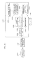
- the network-node equipment further comprises: a device of synchronizing the clock time of each of the network-node equipments; and a device of information-storing that stores new information of changing wavelength of the optical signals, and the information of reconfiguring time of the logical network topology including the time at which wavelength change should be executed, and the device of wavelength switching switches the wavelengths of the optical signals at a predetermined time in accordance with the information of reconfiguring time of the logical network topology and the information of changing wavelength.
- the central-management-equipment further comprises a device of distributing clock time information that distributes clock time information to each of the network-node equipments;
- the controlling unit comprises a device of generating new information of changing wavelength of the optical signals of each of the network-node equipments, and information of reconfiguring time of the logical network topology including the time the wavelength change should be executed, and transmitting them separately or all together to the network-node equipment;
- the network-node equipment comprises: a device of adjusting clock time that adjusts its own clock time in accordance with the information of clock time distributed from the central-management-equipment, and a device of information-storing that receives and stores the information of changing wavelength and the information of reconfiguring time of the logical network topology transmitted from the central-management-equipment; and the device of wavelength switching switches the wavelength of the optical signals at a predetermined time in accordance with the information of reconfiguring time of the logical network topology and the information of changing wavelength.
- a specific network-node equipment among the network-node equipments comprises a device of distributing clock time information that distributes clock time information to other network-node equipments;
- the other network-node equipments comprise a device of adjusting clock time that adjusts their own clock time in accordance with the clock time information distributed from the specific network-node equipment;
- the specific network-node equipment comprises a device of generating information of changing wavelength of the optical signals of the network-node equipment, and information of reconfiguring time of the logical network topology including the time the wavelength change should be executed, and transmitting them separately or all together to the network-node equipments;
- the other network-node equipments comprise a device of information-storing that stores the information of changing wavelength and the information of reconfiguring time of the logical network topology received from the specific network-node equipment; and the device of wavelength switching of the other network-node equipments switches the wavelengths of the optical signals at a predetermined time in
- a central-management-equipment that is connected to M (where M is an integer no smaller than 2, nor greater than an integer N) network-node equipments connected via optical transmission paths and configured so as to form a geometrically star-shaped physical star topology having in the center an arrayed waveguide grating (AWG) that has N optical input ports (where N is an integer greater than or equal to 2) and N optical output ports and a routing function that outputs to predetermined optical output ports in accordance with a wavelength of optical signals inputted to respective optical input ports
- the central-management-equipment comprises a device of controlling that transmits to the network-node equipments a control signal that includes information of changing wavelength of the optical signals and causes the switching of the wavelength of the optical signals, and receives from the network-node equipments a control signal that includes information of communication status, in order to dynamically change a logical network topology that indicates a geometrical form of routes of the optical signals used for transmitting/recei
- a network-node equipment that is connected to M (M is an integer greater than or equal to 1 and less than or equal to N-1) other network-node equipments via an arrayed waveguide grating (AWG) that has N (N is an integer greater than or equal to 2) optical input ports and N optical output ports and a routing function that outputs to predetermined optical output ports in accordance with a wavelength of optical signals inputted to respective optical input ports, comprising: a device of synchronizing clock time that synchronizes the clock time of each of the other network-node equipments; a device of information-storing that stores new information of changing wavelength of optical signal, for dynamically changing a logical network topology that indicates a geometrical form of routes of the optical signals used for transmitting/receiving data between other network-node equipments (hereunder referred to as optical signals), and information of reconfiguring time of the logical network topology that includes the time at which changing wavelength should be executed; and a
- the fiber optic communication system of the present invention dynamically reestablishes a communication destination or logical network topology by dynamically reconfiguring optical paths by means of the wavelength tunable light source, an optical switch, or a wavelength tunable filter arranged in the network-node equipment; and enables topology reconfiguration from a central-management-equipment that unifies the network, or a network-node equipment, in a network where optical signals and control signals can be transmitted and received through the same optical transmission path, between the network-node equipment and the uniform-loss and cyclic-frequency (ULCF) arrayed waveguide grating (AWG), and enables control of competition of requests for topology reconfiguration from random network-node equipment; and enables speedy topology reconfiguration at specified scheduled times by synchronizing the clock time of all the network-node equipments.
- ULCF uniform-loss and cyclic-frequency
- the above-mentioned fiber optic communication system can be easily configured by using the central-management-equipment and the network-node equipments of the present invention.
- a fiber optic communication system comprising: an array waveguide grating (AWG) that has N (N is an integer greater than or equal to 2) optical input ports, M (M is an integer greater than or equal to 2) optical output ports, and a routing function that outputs to predetermined optical output ports in accordance with the wavelength of the optical signals inputted to respective optical input ports; L (L is an integer greater than or equal to 2) network-node equipments; and optical fibers that physically connect the network-node equipments with the array waveguide grating to form communication routes; and having a device of setting wavelength switching of the optical signals used in communication by the network-node equipments, which sets the mapping of the wavelengths of the optical signal used in communication by the network node equipments, and the input/output ports of the array waveguide grating (AWG), so as to construct a predetermined logical network topology by two or more network node equipments.
- N is an integer greater than or equal to 2
- M is an integer greater than or equal to 2
- L is an
- the fiber optic communication system has: two or more logical network topologies configured with two or more network-node equipments; and a device of wavelength switching that switches wavelengths of optical signals used by the network node equipments for communication, when network node equipments belonging to a predetermined logical network topology are connected or moved to another logical network topology.
- the device of wavelength switching is constructed having either one of a multi-wavelength light source array provided in the network-node equipment, a plurality of transceivers that transmit and receive optical signals of different wavelengths, or a wavelength tunable light source.
- the device of wavelength switching is provided in the network-node equipment, and is constructed with a wavelength tunable filter, which transmits only light of a predetermined wavelength, provided on the receiving side.
- At least one of either a ring-shaped logical network topology, a star-shaped logical network topology, or a mesh-shaped logical network topology is provided as the above mentioned logical network topology.
- two or more arrayed waveguide gratings that are connected to enable mutual communication are provided.
- the network-node equipment has two or more different wavelength paths connected to the arrayed waveguide grating (AWG), and a ring-shaped logical network topology that includes two or more communication terminals or network-node equipments is formed as a logical network topology.
- AMG arrayed waveguide grating
- the network-node equipment has two or more different communication channels connected to the arrayed waveguide grating as primary communication channels, and secondary channels constructed similarly to the primary channels.
- a ring-shaped logical network topology is formed as the above mentioned logical network topology, and each of the network-node equipments belonging to the logical network topology has two communication channels that allow forward and backward communications, and the network-node equipment has a device that, when one communication channel is disconnected, returns and transmits through another communication channel, a signal that was to be inputted from this other communication channel and outputted to the one (disconnected) communication channel.
- a ring-shaped logical network topology is formed as the logical network topology, and in each of the network-node equipments belonging to the ring-shaped logical network topology, two communication channels that allow forward and backward communications are provided, and the network-node equipment is provided with a device of switching and setting the wavelength of optical signals that, in the case where communication with a network-node equipment that uses one communication channel for communication has become unavailable, enables it to bypass this network-node equipment that has lost communication ability, and communicate with an arbitrary network-node equipment.
- each network-node equipment is connected to the arrayed waveguide grating via single-core optical fiber.
- the arrayed waveguide grating comprises a uniform-loss and cyclic-frequency (ULCF) arrayed waveguide grating (AWG).
- ULCF uniform-loss and cyclic-frequency arrayed waveguide grating
- a central-management-equipment is provided to control and manage the wavelength switching device installed in each network-node equipment, and by connecting a transceiver for management that is installed in the central-management-equipment, and a transceiver for management that is installed in the network-node equipment to each other, transmitting and receiving of management data signals is enabled.
- each of the network-node equipments and the arrayed waveguide gratings is provided with a device of combining, which combines the optical signals of the data signals transmitted between each of the network-node equipments with the optical signals of the data signals for management, and a device of splitting, which splits the combined optical signals of the optical signals of the data signals, and the optical signals of the data signals for management, into optical signals of the data signals and optical signals of the data signals for management, and the channel that transmits the optical signals of the data signals for management is physically shared with the optical fiber that transmits the optical signal of the data signals.
- the network that transmits the optical signals of the data signals for management and the optical signals of the data signals transmits them through different communication channels.
- a topology reconfigurable optical network system which, in a network system in which a network-node equipment is provided with three kinds of optical input/output ports, namely; optical in/output ports for network-terminal equipments for connecting to a communication terminal such as a router or computer, optical in/output ports for WDM data-signals that function as an interface for transmitting and receiving optical signals with other network-node equipments, and optical in/output ports for control signals; and the optical in/output ports for WDM data-signals of the two or more of the network-node equipments are physically connected via optical paths such as optical fibers to the optical input/output ports of an arrayed waveguide grating that performs wavelength routing of the optical signal according to the wavelength of the optical signal; and furthermore, the optical input/output ports for control signals of the central-management-equipment that is provided to remotely control the oscillating wavelengths of one or more wavelength tunable light sources installed in the network-
- the network-node equipment is provided with 2N (N is an integer greater than or equal to 2) E/O converters that convert optical signals inputted from the network terminal equipment through the optical in/output ports for network-terminal, into electrical signals, or convert electrical signals into optical signals and transmit them to the network-node equipments, and regarding these 2N E/O converters, the N output ports of a 2Nx2N switch that is disposed in the network-node equipment are connected in series to N wavelength tunable light sources and N optical receivers, and the N wavelength tunable light sources are connected in series to an Nx1 optical coupler installed in the network-node equipment, and the optical in/output ports for WDM data-signals, and the N input ports of the 2Nx2N switch are connected in series to N optical receivers installed in the network-node equipment, an Nx1 optical splitter, and the optical in/output ports for WDM data-signal.
- 2N is an integer greater than or equal to 2N E/O converters
- a device in which the 2Nx2N switch is controlled so as to establish a channel for an optical signal that arrives at the optical in/output ports for WDM data-signal from the arrayed waveguide grating, to travel through: the Nx1 splitter - the optical receivers - the 2Nx2N electrical switch - the wavelength tunable light sources - the Nx1 optical couplers - the optical in/output port for WDM data-signal in this order, so that without allowing the optical signal to reach the network terminal equipment, the wavelength of optical signals is converted and is re-transmitted to and received by the arrayed waveguide grating.
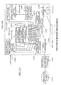
- the central-management-equipment is provided with: a device of transmitting and receiving control signals that serves as the control signal interface between all the network node equipments, and that performs transmission and reception of control signals between the optical input/output port for control signals and the network node equipments via the optical input/output port for control signals; a device of monitoring that monitors the status of all of the network-node equipments in accordance with the control signals; a device of charge calculation that calculates a charge for every wavelength path of each network-node equipment used in the network in accordance with the result of the monitoring; and a device of controlling display of a topology administrator console interface.
- a device of reading from the node database of the network-node equipment in response to a request from the central-management-equipment respective information for the network-node equipment on: the available wavelength bandwidth, all wavelengths currently in use, transmitting optical power status and receiving optical power status of the optical signals of each wavelength, connection status between the network node equipments, and the logical network topology currently connected, and notifying this to the central-management-equipment.
- the central-management-equipment has a device of detecting abnormalities in the connection status of all of the network-node equipments, and the transmitting optical power status and receiving optical power status of the wavelength signal in the network-node equipment, and notifying all of the network-node equipments, and the network-node equipment has a device of always monitoring the transmitting optical power status and receiving optical power status of the wavelength signal, and detecting an abnormality if it occurs in these statuses, and notifying the central-management-equipment.
- a device which in the case where a ring-shaped logical network topology is configured, when there occurs any one of: a failure in the network terminal connected to a predetermined network-node equipment, or a failure in the predetermined network-node equipment, or a disconnection failure in the optical waveguide connecting the predetermined network-node equipment and the array waveguide grating (AWG), transmits from the central-management-equipment to the network-node equipment in which the failure has occurred, a command that shuts down the wavelength tunable light source, and transmits to each of the two network-node equipments being closest to and connected to the network-node equipment in which the failure occurred, a command that reconfigures the wavelength allocation so as to bypass the network node equipment in which the failure has occurred, and reconfigures a logical network topology in which the network-node equipment in which the failure occurred is bypassed.
- AMG array waveguide grating
- a device which in the case where a ring-shaped logical network topology is configured, when there occurs any one of: a failure in the network terminal connected to a predetermined network-node equipment, or a failure in the predetermined network-node equipment, or a disconnection failure in the optical waveguide connecting the predetermined network-node equipment and the array waveguide grating (AWG), notifies a command from the central-management-equipment to the network-node equipment in which the failure has occurred to shut down the wavelength tunable light source, and notifies to each of the two network-node equipments being closest to and connected to the network-node equipment in which the failure occurred, a command that reconfigures the wavelength allocation so as to bypass the network node equipment in which the failure has occurred, and reconfigures a logical network topology in which the network-node equipment in which the failure occurred is bypassed.
- a status of currently using wavelength that the network-terminal administrator of the network-node equipment is using on the network-node equipment, and a connected current logical topology network, a logical topology reconfiguration schedule, a failure notification, and a request for failure history are configured as a management gateway for the network-node equipment to report to the network-terminal administrator.
- the central-management-equipment is provided with: a device which, when a network-node-equipment launches a request to the central management equipment for changing connection from a logical network topology to which it is currently connected to a different logical network topology, determines whether or not to conform by querying the central database and performing a computation; and a device which, if the result of the determination is to conform, notifies all of the network-node equipments within the logical network topology to which the network-node equipment that launched the request of logical network topology connection change is connected, of disengagement of the network-node equipment and wavelength resetting of the optical signal, and updates the stored information of the central database and the node databases; and a device that notifies all of the network-nodes of the logical network topology to which the network-node equipment which launched the request of logical network topology connection change is transferring, of the addition and wavelength resetting of the network
- the central-management equipment is provided with: a device of referencing the central database, and computing the additional charge required for the new wavelength path channel, and recording the result of the computation in the central database, when a request of changing logical topology is performed in a specific network-node equipment, and a new wavelength path channel is established when topology reconfiguration is performed; and a device of notifying information of the additional charge to the network-node equipment.
- the central-management equipment is provided with a device of referencing the central database and computing a waiver of the charge for a terminated wavelength path channel and recording the result of the computation in the central database, when a request for changing logical topology is performed in a specific network-node equipment, and a wavelength path channel is terminated when the topology reconfiguration is performed, and the information of the waiver of the charge for the terminated wavelength path channel is notified to the network-node equipment.
- the central-management equipment is provided with at least one of either: a device which, when traffic flow between specific network-node equipments increases and network load occurs, and a request is launched to the central-management-equipment from the network-node equipment for a bandwidth increase between the network-node equipments, determines whether or not the bandwidth increase is possible by querying the central database and computing, and when determined that a bandwidth increase between the network-node equipments is possible by connecting through a predetermined network-node equipment to which the network-node equipment has not hitherto been connected, and adding a new rerouting wavelength path, notifying the wavelength configuration for configuring a new wavelength path channel between the predetermined network-node equipment for rerouting and the specific network-node equipment, to respective network-node equipments of the network-node equipment, and executing the configuration of the new wavelength path channel, and updating information stored in the central database; or a device which
- a network-node equipment comprising: a device of controlling wavelength tunable light source that outputs a wavelength control signal that individually controls the oscillating wavelength of the wavelength tunable light source; a device of monitoring that monitors the power of the optical output outputted from the wavelength tunable light source and the power of the optical signal inputted to the optical receiver; a device of switch controlling that outputs the 2Nx2N switch control signal; a device of management that has a node database, and that holds the available wavelength list in the node database, and also records the wavelength currently in use in the node database, and changes the data of wavelengths in use registered on the database according to the information monitored by the device of monitoring, when the wavelength in use between network-node equipments changes; a display control device that displays information monitored by the monitoring device and information that is managed by the management device; and a device of transmitting and receiving control signals that connects the optical in/output port for control signals.
- a central-management-equipment which in a central-management-equipment that is connected to the network-node equipment via optical waveguides in a fiber optic communication system having two or more network-node equipments and an arrayed waveguide grating (AWG) connecting these network-node equipments, and that performs operation control of the network-node equipment, comprising: a central database provided at in least one of either inside or outside of the equipment; a device of recording all wavelengths in use in each of the network-node equipments, and monitoring transmitting optical power status and receiving optical power status of the wavelengths in use in each of all these network-node equipments and recording them in the central database; a device of monitoring connection status between the network-node equipments and recording it in the central database; a device of monitoring connection status between the network-node equipment and a network terminal equipment and recording it in the central database; a device of changing the wavelength used that is registered in the central database when
- a device of transmitting and receiving control signals that performs transmission and reception of control signals between the optical input/output port for control signals that serves as the control signal interface between all the network node equipments and the network node equipments via the optical input/output port for control signals; a device of monitoring that monitors the status of all of the network-node equipments in accordance with the control signals; a device of charge calculation that calculates a charge for every wavelength path of each network-node equipment used in the network according to the result of the monitoring; and a device of controlling display of a topology administrator console interface.
- a computer program for a network-node equipment which, in a computer program that operates a network-node equipment that has three kinds of input/output ports namely: optical in/output ports for network-terminal equipments; optical in/output ports for WDM data-signals, that convert, transmit, and receive optical signal wavelengths from a network terminal equipment; and control signal input/output ports, and that is provided with 2N (N is an integer greater than or equal to 2) E/O converters that convert optical signals inputted from the network terminal equipment through the optical in/output ports for network-terminal equipments into electrical signals, or convert electrical signals into optical signals and transmit them to the network terminal equipment, and these 2N E/O are connected in series to N output ports of a 2Nx2N switch that is disposed on the network-node equipment, and connected in series to N wavelength tunable light sources and N optical receivers, and the N wavelength tunable light sources are connected in series to an Nx1 optical coupler installed
- a computer program of a central-management-equipment which, in a computer program that operates a central-management-equipment that comprises a computer equipment that performs operation control and operation processing of a network-node equipment, and that is connected to the wavelength tunable light source equipment via optical waveguides in a fiber optic communication system having two or more network-node equipments and an arrayed waveguide grating (AWG) connecting these network-node equipments, and performs operation control of the network-node equipment, comprising: a step for recording all of the wavelengths in use in each of the network-node equipments and monitoring transmitting optical power status and receiving optical power status for every wavelength in use in each of all these network-node equipments and recording them in the central database; a step for monitoring connection status between the network-node equipments and recording it in the central database; a step for monitoring connection status between the network-node equipment and a network terminal equipment and recording it in the central
- the above mentioned computer program comprises: a step for performing transmitting and receiving of control signals between the network-node equipments; a step for monitoring the status of all the network-node equipments according to the control signals; and a step for performing charge calculation for each wavelength path of respective network-node equipments used in the network.
- a fiber optic communication system which, in a fiber optic communication system having a star-shaped physical network topology configured by connecting M (M is an integer no smaller than 2, nor greater than N) network-node equipments having data-signal transmitting and receiving units to an arrayed waveguide grating provided with an NxN wavelength routing device having N (N is an integer greater than or equal to 2) input ports and N output ports via optical waveguides, comprising: a device of reconfiguration that sweeps transmitting and receiving wavelengths used in the data-signal transmitting and receiving unit of each network-node equipment and dynamically reconfigures the logical network topology of the network, and the device of reconfiguration comprises: a network-management-system equipment capable of transmitting control signals that include information of changing wavelength, and receiving control signals from each network node; and a controlling unit of network-node equipment that receives control signals from the network-management-system equipment provided on each network-node equipment and sweeps transmitting and receiving wavelengths used in the
- the arrayed waveguide grating is provided with a WDM coupler that combines the control signal from the network-management-system equipment with the output signal from the arrayed waveguide grating, and also with a WDM coupler that splits input signals from each network-node equipment into data-signals and control signals, and transmits the control signals to the network-management-system equipment and inputs the data-signals to the arrayed waveguide grating (AWG).
- WDM coupler that combines the control signal from the network-management-system equipment with the output signal from the arrayed waveguide grating
- WDM coupler that splits input signals from each network-node equipment into data-signals and control signals, and transmits the control signals to the network-management-system equipment and inputs the data-signals to the arrayed waveguide grating (AWG).
- the data-signal transmitting and receiving unit of each network-node equipment is provided with L (L is an integer no smaller than 2, nor greater than M) wavelength tunable light sources having a modulator on the output side or having a direct modulation function, and L optical receivers.
- each network-node equipment is provided with: a first WDM coupler that splits the input signal from the arrayed waveguide grating into a data-signal and a control signal, and transmits the control signal to the controlling unit of network-node equipment; an optical splitter that splits the data-signal from the first WDM coupler by wavelength; NxL first optical switches that change the channel of the data-signal from the optical splitter and transmit it to the L optical receivers; NxL optical switches that change the channel of the data signal from the L wavelength tunable light sources; an optical combiner that combines the data-signal from the optical switches; and a second WDM coupler that combines the data-signal from the optical combiner with the control signal from the controlling unit of network-node equipment, and outputs it.
- a first WDM coupler that splits the input signal from the arrayed waveguide grating into a data-signal and a control signal, and transmits the control signal to the controlling unit of network-node
- the data-signal transmitting and receiving unit of each network-node equipment is provided with; L (L is an integer no smaller than 2, nor greater than M) wavelength tunable light sources having a modulator on the output side or having a direct modulation function, and L optical receivers having wavelength tunable filters on their input side.
- each network-node equipment is provided with: the first WDM coupler that splits the input signal from the arrayed waveguide grating into a data-signal and a control signal and transmits the control signal to the controlling unit of network-node equipment; a first coupler that distributes and transmits the data-signals from the first WDM coupler respectively into the L optical receivers; a second coupler that combines the data-signals from the L wavelength tunable light sources; and a second WDM coupler that combines the data-signal from the second coupler with the control signal from the controlling unit of network-node equipment, and outputs it.
- each network-node equipment and the arrayed waveguide grating are respectively provided with an optical circulator that changes the channels of the input signal and the output signal, and each network-node equipment and the arrayed waveguide grating are respectively connected via single-core optical transmission lines.
- the arrayed waveguide grating is provided with a wavelength routing device not having uniform loss and cyclic frequency characteristics, comprising an arrayed waveguide grating type optical combiner/splitter.
- the arrayed waveguide grating is provided with a wavelength routing device having uniform loss and cyclic frequency characteristics, comprising an arrayed waveguide grating type optical combiner/splitter.
- a network-node equipment which, in a network-node equipment in a fiber optic communication system having a star-shaped physical network topology configured by connecting M (M is an integer no smaller than 2, nor greater than N) network-node equipments having data-signal transmitting and receiving units to an arrayed waveguide grating provided with an NxN wavelength routing device having N (N is an integer greater than or equal to 2) input ports and N output ports via optical waveguides, comprisinga controlling unit of network-node equipment that receives a control signal including information of changing wavelength and sweeps transmitting and receiving wavelengths used in the data-signal transmitting and receiving unit, and also transmits a control signal including information of communication status.
- the data-signal transmitting and receiving unit is provided with L (L is an integer no smaller than 2, nor greater than M) wavelength tunable light sources having a modulator on the output side or having a direct modulation function, and L optical receivers.
- a first WDM coupler that splits the input signal from the arrayed waveguide grating into a data-signal and a control signal, and transmits the control signal to a controlling unit of network-node equipment; an optical splitter that splits the data-signal from the first WDM coupler by wavelength; NxL optical switches that change the channel of the data-signal from the optical splitter and transmit it to the L optical receivers; NxL second optical switches that change the channel of the data signal from the L wavelength tunable light sources; an optical combiner that combines the data-signal from the second optical switches; and a second WDM coupler that combines the data-signal from the optical combiner with the control signal from the controlling unit of network-node equipment, and outputs it.
- the data-signal transmitting and receiving unit is provided with L (L is an integer no smaller than 2, nor greater than M) wavelength tunable light sources having a modulator on the output side or having a direct modulation function, and L optical receivers having wavelength tunable filters on their input side.
- the first WDM coupler that splits the input signal from the arrayed waveguide grating into data-signals and a control signal and transmits the control signal to the controlling unit of network-node equipment; a first coupler that distributes and transmits the data-signals from the first WDM coupler respectively into the L optical receivers; a second coupler that combines the data-signals from the L wavelength tunable light sources; and a second WDM coupler that combines the data-signals from the second coupler with the control signal from the controlling unit of network-node equipment, and outputs it.
- an optical circulator that changes the channel of the input signal and the output signal is provided.
- a fiber optic communication system which, in a fiber optic communication system that is configured with: an arrayed waveguide grating and N (N is an integer that satisfies 2 ⁇ N ⁇ M, where M is an integer greater than or equal to 2) network-node equipments, and the arrayed waveguide grating is provided with respectively M optical input ports and optical output ports; and the N network-node equipments are provided with L (L is an integer no smaller than 2, nor greater than N) wavelength tunable optical receiver units constructed with L wavelength tunable light source units and wavelength tunable filters, and a controlling unit that controls the wavelength tunable light source units and wavelength tunable optical receiver units, and are connected to the arrayed waveguide grating via optical transmission lines and form a star-shaped physical topology; and by controlling the output wavelength of the wavelength tunable light source and the receiving wavelength of the wavelength tunable optical receiver unit by the controlling unit, different network-node equipments that are counter-connected are arbitrarily selected
- a central-management-equipment having a device of distributing clock time information that distributes clock time information to each network-node equipment
- the network-node equipment has a device of adjusting clock time that corrects own clock time according to information of clock time distributed from the central-management-equipment, and the clock times of all the network-node equipments are synchronized according to the information of clock time distributed from the central-management-equipment.
- the central-management-equipment is provided with a device of individually transmitting to the network-node equipments, information of changing wavelength and information of reconfiguring time of the logical network topology for each of the network-node equipments, which is required when the logical network topology is reconfigured, and the device of information storing of the network-node equipments has a device of storing information of changing wavelength and information of reconfiguring time of the logical network topology received from the central-management-equipment.
- a specific network-node equipment is provided with a device of distributing clock time information that distributes clock time information to other network-node equipments, and the other network-node equipments have a device of adjusting clock time that corrects own clock time according to the information of clock time distributed from the specific network-node equipment, and the clock times of all the network-node equipments are synchronized in accordance with the information of clock time distributed from the specific network-node equipment.
- the above mentioned specific network-node equipment is provided with a device of individually transmitting to the network-node equipments, information of changing wavelength and information of reconfiguring time of the logical network topology for each of the network-node equipments, which is required when the logical network topology is reconfigured, and the device of information storing of the other network-node equipments has a device of storing information of changing wavelength and information of reconfiguring time of the logical network topology received from the specific network-node equipment.
- the above mentioned central-management-equipment is provided with a network management equipment having a device of logical network topology reconfiguring operation for an administrator to input information of the logical network topology reconfiguration, and the logical network topology can be reconfigured by the administrator.
- the above mentioned specific network-node equipment is provided with a network management equipment having a device of logical network topology reconfiguring operation for an administrator to input information of the logical network topology reconfiguration, and the logical network topology can be reconfigured by the administrator.
- all of the network-node equipments are provided with a network management equipment having a device of logical network topology reconfiguring operation for an administrator to input information of the logical network topology reconfiguration, and the logical network topology can be reconfigured by the administrator.
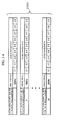
- the above mentioned network-node equipment is provided with: a device of generating network-node equipment status information that indicates the status of the network-node equipment before and after logical network topology reconfiguration; a device of transmitting and receiving status information of network-node equipment that transmits and receives status information of network-node equipment between the network-node equipments; and a device of recording status information of network-node equipment that records status information of network-node equipment of each network-node equipment.
- the above mentioned network-node equipment is provided with: a device of generating network-node equipment status information that indicates the status of the network-node equipment before and after logical network topology reconfiguration; and a device of transmitting the network-node equipment status information to the central-management-equipment; and the central-management-equipment is provided with: a device of receiving and recording the network-node equipment status information that the network-node equipment, which reconfigures the logical network topology, transmits; and a device of managing status information of network-node equipment that performs uniform management of the network-node equipment status information of all the network-node equipments.
- the above mentioned network-node equipment is provided with: a device of generating network-node equipment status information that indicates the status of the network-node equipment before and after logical network topology reconfiguration; and a device of transmitting the network-node equipment status information to the specific network-node equipment; and the specific network-node equipment is provided with: a device of receiving and recording the network-node equipment status information that the network-node equipment, which reconfigures the logical network topology, transmits; and a device of managing status information of network-node equipment that performs uniform management of the network-node equipment status information of all the network-node equipments.
- all of the above mentioned network-node equipments are provided with a device that, before logical network topology reconfiguration begins, transmits a requesting status information of logical network topology reconfiguration, after the information of network node equipment status is changed into the requesting status information of network topology reconfiguration.
- the above mentioned network-node equipment is provided with a device of receiving requesting status information of logical network topology reconfiguration from other network-node equipment; and a device which when the requesting status information of logical network topology reconfiguration is received, returns an authorization message or a denial message of logical network topology reconfiguration to the network-node equipment of sender, and the network-node equipment, which is the sender of the requesting status information of logical network topology reconfiguration, is provided with a device of withholding reconfiguration of own logical network topology when the denial message of the logical network topology reconfiguration is received.
- the above mentioned network-node equipment is provided with: a device of searching for the presence of requesting status information of logical network topology reconfiguration in the recorded information of network node equipment status of the other network-node equipments; and a device that suppresses logical network topology reconfiguration when the requesting status information of logical network topology reconfiguration is found as a result of the search.
- the optical signal wavelength of the control signals transmitted between each of the network-node equipments is configured to be of a different wavelength from the wavelength bandwidth of the data-signal used for connecting the network-node equipments
- WDM couplers capable of combining and splitting the data-signal and the control signals are arranged in the network-node equipment and the arrayed waveguide grating respectively, and the optical transmission line used for the data-signal is shared as an optical transmission line for the control signals.
- the optical transmission lines of the control signal transmitted between each equipment are provided separately from the optical transmission lines of the data-signal used for connecting the network-node equipments.
- the transmission lines of the control signals transmitted between each of the equipments is formed by public networks or the Internet.
- optical elements installed in the L wavelength tunable light source units are constructed in an elemental construction in which a wavelength tunable laser and a modulator are connected in series or are mutually integrated, or alternatively are comprised of a semiconductor laser that allows direct modulation, and a construction is provided in which these are connected by the Lx1 optical coupler, and the L wavelength tunable optical receiver units have a construction in which optical receivers and wavelength tunable filters connected in series are connected to the Lx1 optical coupler.
- the optical elements installed in the L wavelength tunable light source units are constructed in an elemental construction in which a wavelength tunable laser and a modulator are connected in series or are mutually integrated, or alternatively comprise a semiconductor laser that allows direct modulation, and a construction is provided in which these optical elements are connected in series to an LxN switch and an Nx1 optical coupler which are connected in series, and the L wavelength tunable optical receiver units are comprised of optical receivers and wavelength tunable filters, which are respectively connected in series, and have a construction in which these wavelength tunable optical receiver units are connected in series to LxN switches and Nx1 optical coupler which are connected in series.
- the arrayed waveguide grating is an arrayed waveguide grating having M inputs and M outputs.
- the arrayed waveguide grating is a uniform-loss and cyclic-frequency (ULCF) arrayed waveguide grating having M inputs and M outputs.
- ULCF uniform-loss and cyclic-frequency
- a central-management-equipment which, in a central-management equipment of a fiber optic communication system, of which the logical network topology is reconfigurable, that is configured with an arrayed waveguide grating, a central-management-equipment, and N (N is an integer that satisfies 2 ⁇ N ⁇ M, where M is an integer greater than or equal to 2) network-node equipments; and the arrayed waveguide grating is respectively provided with M optical input ports and optical output ports; and the N network-node equipments are provided with L (L is an integer no smaller than 2, nor greater than N) wavelength tunable optical receiver units constructed with L wavelength tunable light source units and wavelength tunable filters and a controlling unit that controls the wavelength tunable light source units and wavelength tunable optical receiver units, and are connected to the arrayed waveguide grating via optical transmission lines, and form a star-shaped physical topology; and in which, by controlling output wavelength of the above mentioned wavelength t
- a network-node equipment which, in a network-node equipment of a fiber optic communication system: that is configured with an arrayed waveguide grating, and N (N is an integer that satisfies 2 ⁇ N ⁇ M, where M is an integer greater than or equal to 2) network-node equipments; and the arrayed waveguide grating is provided with respectively M optical input ports and optical output ports; and the N network-node equipments are provided with L (L is an integer no smaller than 2, nor greater than N) wavelength tunable optical receiver units constructed with L wavelength tunable light source units and wavelength tunable filters, and a controlling unit that controls the wavelength tunable light source units and wavelength tunable optical receiver units, and are connected to the wavelength router equipment via optical transmission lines and form a star-shaped physical topology; and in which, by controlling the output wavelength of the wavelength tunable light source units and the receiving wavelength of the wavelength tunable optical receiver units by the controlling unit, different network-node
- a computer program for a topology reconfiguration controlling equipment which, in a computer program for a topology reconfiguration controlling equipment of a fiber optic communication system, of which the logical network topology is reconfigurable, that is configured with an arrayed waveguide grating, and N (N is an integer that satisfies 2 ⁇ N ⁇ M, where M is an integer greater than or equal to 2) network-node equipments; and the arrayed waveguide grating is respectively provided with M optical input ports and optical output ports; and the N network-node equipments are provided with L (L is an integer no smaller than 2, nor greater than N) wavelength tunable optical receiver units constructed with L wavelength tunable light source units and wavelength tunable filters, and a controlling unit that controls the wavelength tunable light source units and wavelength tunable optical receiver units, and are connected to the wavelength router via optical transmission lines, and form a star-shaped physical topology; and in which, by controlling output wavelength of the wavelength tunable light source units and the
- a computer program for a network-node equipment which, in a computer program for a network-node equipment of a fiber optic communication system of which the logical network topology is reconfigurable, that is configured with an arrayed waveguide grating, and N (N is an integer that satisfies 2 ⁇ N ⁇ M, where M is an integer greater than or equal to 2) network-node equipments comprising computer equipments; and the arrayed waveguide grating is respectively provided with M optical input ports and optical output ports, and the N network-node equipments are provided with L (L is an integer no smaller than 2, nor greater than N) wavelength tunable optical receiver units constructed with L wavelength tunable light source units and wavelength tunable filters and a controlling unit that controls the wavelength tunable light source units and the wavelength tunable optical receiver units, and are connected to the arrayed waveguide grating via optical transmission lines, and form a star-shaped physical topology in which the connections formed by transmission lines formed by
- a computer program for a network-node equipment which, in a computer program for a network-node equipment of a fiber optic communication system of which the logical network topology is reconfigurable, that is configured with an arrayed waveguide grating, and N (N is an integer that satisfies 2 ⁇ N ⁇ M, where M is an integer greater than or equal to 2) network-node equipments comprising computer equipments; and the arrayed waveguide grating is respectively provided with M optical input ports and optical output ports, and the N network-node equipments are provided with L (L is an integer no smaller than 2, nor greater than N) wavelength tunable optical receiver units constructed with L wavelength tunable light source units and wavelength tunable filters and a controlling unit that controls the wavelength tunable light source units and the wavelength tunable optical receiver units, and are connected to the arrayed waveguide grating via optical transmission lines, and form a star-shaped physical topology in which the connections formed by transmission lines formed by
- the numbers 4, 5, 13 or 14 are respectively given for the number of optical input/output ports of an arrayed waveguide grating (AWG) N, and for the number of network-node equipments M, however, they are not limited to these numbers, and need only be two or more.
- an optical amplifier may be needed due to the optical transmission loss when configuring the network, and this optical amplifier may be installed anywhere between transmitting and receiving equipment.
- FIG. 1-1 Network-node equipment and a physical network topology that is physically connected via optical fibers of an arrayed waveguide grating (AWG) of a first embodiment according to the fiber optic communication system of the present invention is shown in FIG. 1-1.
- AMG arrayed waveguide grating
- an arrayed waveguide grating (AWG) 1-101 has optical input ports 1-201 to 1-205 and optical output ports 1-301 to 1-305, and each of these optical input/output ports 1-201 to 1-205 and 1-301 to 1-305 is connected to network-terminal equipments such as personal computers, or network-node equipments such as routers that are nodal points of a communication network 1-404 to 1-405, which are disposed in the periphery. Also, each of the network-node equipments 1-401 to 1-405 is provided with a device of switching the wavelength of optical signals used for communication (not shown in the diagram).
- FIG. 1-2 is an example of connecting the arrayed-waveguide grating (AWG) 1-101 and each network-node equipment 1-401 to 1-405 by two-core optical fibers
- FIG. 1-3 is an example of connecting the arrayed-waveguide grating (AWG) 1-101 and each network-node equipment 1-401 to 1-405 by single-core optical fibers.
- AMG arrayed-waveguide grating
- optical signals 1-601 to 1-605 that are transmitted from each network-node equipment 1-401 to 1-405 and inputted to the optical input ports 1-201 to 1-205, are outputted for each of their wavelengths to the optical output ports 1-301 to 1-305 that correspond to the wavelengths.
- optical signals having wavelengths set in the destination (transmission destination) network-node equipment 1-401 to 1-405 may be switched and selected and transmitted from each of the network-node equipments 1-401 to 1-405, and logically a star-shaped (mesh-shaped) network topology as shown in FIG. 1-4 or a different logical network topology such as a ring-shaped network topology as shown in FIG. 1-5 can be easily realized, while physically having a simple star-shaped configuration as in the physical network topology shown in FIG. 1-1.
- FIG. 1-4 and FIG. 1-5 respectively show an image of the signal transmission route (wavelength path) and the logical network topology configuration of the communication route.
- connection relationships which are based on the wavelengths of the optical signals of the optical input/output ports 1-201 to 1-205 and 1-301 to 1-305 in the arrayed waveguide grating (AWG) 1-101, and the wavelengths of the optical signals used on each network-node equipment 1-401 to 1-405 need only to be set according to the wavelength allocation in FIG. 1-6.
- the wavelengths highlighted with hatching are to be used.
- connection relationships which are based on the wavelengths of the optical signals of the optical input/output ports 1-201 to 1-205 and 1-301 to 1-305 in the arrayed waveguide grating (AWG) 1-101, and the wavelengths of the optical signals used on each network-node equipment 1-401 to 1-405 need only to be set according to the wavelength allocation in FIG. 1-7.
- the wavelengths highlighted with hatching are to be used.
- Changing a group of network-node equipments that configure a logical network topology into another logical network topology can be achieved by having each network-node equipment switch the wavelengths of the optical signals in accordance with the wavelength allocation for the other logical network topology.
- AWG arrayed waveguide gratings
- FIG. 1-8 to FIG. 1-10 A second embodiment according to the fiber optic communication system of the present invention is shown in FIG. 1-8 to FIG. 1-10.
- the characteristics of the present invention are described in detail, taking as an example a method of extending the fiber optic communication system.
- the second embodiment is a case where a simple physical star-shaped network topology configuration as shown in FIG. 1-8 is realized on a small scale.
- a case is shown in which five base stations 1-402A to 1-406A provided with network-node equipments 1-402 to 1-406 are connected to a center base station 1-401A having the arrayed waveguide grating (AWG) 1-101 described in the first embodiment.
- AWG arrayed waveguide grating
- FIG. 1-9 shows the physical network configuration when the network configuration shown in FIG. 1-8 is extended and the number of network-node equipments is increased
- FIG. 1-10 shows the configuration of the logical network topology in the configuration of FIG. 1-9.
- the fiber optic communication network shown in FIG. 1-9 is an example providing extended base stations 1-407A to 1-418A having network-node equipments 1-407 to 1-418 that are connected to the arrayed waveguide grating (AWG) 1-101 of the center base station 1-401 A. Also, in the fiber optic communication network shown in FIG. 1-9, as shown in FIG.
- a ring-shaped logical network topology is configured with base stations 1-401A and 1-402A and extended base stations 1-407A and 1-408A;
- a star-shaped logical network topology is configured with base stations 1-401A and 1-406A and extended base stations 1-413A to 1-416A;
- a ring-shaped logical network topology is configured with base stations 1-401A and 1-405A and extended base stations 1-409A to 1-412A;
- a star-shaped logical network topology is configured with base stations 1-401A, 1-403A and 1-404A and extended base stations 1-417A and 1-418A.
- a star-shaped (mesh-shaped) logical network topology is configured with base stations 1-401A and 1-405A and extended base stations 1-412A and 1-418A.
- a large-scale network such as that shown in FIG. 1-9 is not usually constructed in the initial stage of network construction, and it is usual to expand the scale of the network step by step from a network configuration such as the one shown in FIG. 1-8, by expansion of the scale of the network while the network is operating.
- AMG arrayed waveguide gratings
- the size of the network when extending, by connecting the network-node equipments 1-407 to 1-418 to the arrayed waveguide grating (AWG) 1-101 via optical fibers to establish additional extended base stations 1-407A to 1-418A, the size of the network can be easily upscaled without interrupting or stopping the communication status of the network-node equipments 1-401 to 1-406 that have already been established.
- AMG arrayed waveguide grating
- a fiber optic communication system can be constructed in which different logical network topologies such as a mesh-shaped one, a star-shaped one, and a ring-shaped one coexist on the same star-shaped physical star network topology, as shown in FIG. 1-10.
- the network-node equipments that are to be connection destinations can be selected simply by changing the wavelengths of the optical signals that each of the network-node equipments 1-401 to 1-418 transmit and receive, then when reconfiguring a logical network topology, reconnection of optical fibers in the initial physical network configuration does not require a long time and high-cost construction work is not required, so that the logical network topology can be reconfigured extremely easily in a short period of time at low cost.
- the logical network topology may also be reconfigured by changing the wavelength allocation of the optical input/output ports in the arrayed-waveguide grating (AWG) 1-101.
- FIG. 1-11 shows a physical network topology that is a physical network configuration
- FIG. 1-12 shows the logical network topology thereof
- FIG. 1-13 is a diagram that describes in detail the logical configuration in the network configuration of the third embodiment
- FIG. 1-14 is a diagram showing the wavelength allocation relationships of the optical input/output ports of an arrayed-waveguide grating (AWG) 1-101 of the third embodiment.
- ADG arrayed-waveguide grating
- data centers 1-701A to 1-705A provided with network-node equipments 1-701 to 1-705 are connected via optical fibers to a center base station 1-101A provided with the arrayed-waveguide grating (AWG) 1-101, and base stations 1-706A to 1-713A provided with network-node equipments 1-706 to 1-713 are connected via optical fibers to the center base station 1-101A.
- AMG arrayed-waveguide grating
- the data centers 1-701A to 1-705A configure a mesh-shaped logical network topology and form a distributed data-center WDM (Wavelength Division Multiplexing) core network 1-721, and the network-node equipments 1-701 to 1-705 of the data centers 1-701A to 1-705A and the network-node equipments 1-706 and 1-710 form a MPLS (Multi-Protocol Label Switching) core network 1-722 (Full-mesh logical network topology).
- WDM Widelength Division Multiplexing
- the network-node equipments 1-706 to 1-709 form a RPR (Resilient Packet Ring) network 1-723 (ring-shaped logical network topology), and the network-node equipments 1-710 to 1-713 form an ether network 1-724 (star-shaped logical topology), and then an inter-building connection network 1-725 created by point-to-point connection in a simple star-shaped configuration is formed between the network-node equipment 1-707 and the network-node equipment 1-713.
- RPR Resilient Packet Ring
- ether network 1-724 star-shaped logical topology
- the present embodiment is characterized not only in that the logical network topology can combine a star-shaped (mesh-shaped) logical network topology and a ring-shaped logical network topology despite being a simple star-shaped physical network topology such as that shown in FIG.
- MPLS Multi-protocol Label Switching
- RPR Resilient Packet Ring
- IX Internet exchange
- node numbers 1 to 16 denote port numbers of the optical input/output ports of the arrayed-waveguide grating (AWG) 1-101, and in the present embodiment, the respective optical input/output ports having each of node numbers 1 to 13 are connected to the network-node equipments 1-701 to 1-713, and the wavelength allocation of optical signals for each of the network-node equipments 1-701 to 1-713 is set.
- the network-node equipments 1-706 to 1-709 connected to the ring-shaped logical network topology are connected to the network-node equipments 1-701 to 1-705 of the data centers 1-701A to 1-705A configured with a mesh-shaped logical network topology.
- the network-node equipments 1-701 to 1-705, 1-706, and 1-710 are LSR (Label Switch Routers) of the MPLS
- the network-node equipment 1-706 is a LSR (Label Switch Router) boundary of the MPLS.
- the network-node equipments 1-710 to 1-713 easily realize a logical network configuration that is connected in a simple star-shape, and the network-node equipments 1-710 to 1-713 are connected to the network-node equipments 1-701 to 1-705 of the mesh-connected data centers 1-701A to 1-705A.
- the network-node equipment 1-710 is a LSR (Label Switch Router) boundary of the MPLS.
- wavelengths ⁇ 1 to ⁇ 9 are used in the MPLS core network 1-721 configured with the mesh-shaped logical network topology
- wavelengths ⁇ 12 to ⁇ 16 are used in the PRP network 1-723 configured with the ring-shaped logical network topology
- wavelengths ⁇ 4 to ⁇ 9 are used in the ether network 1-724 configured with the star-shaped logical topology
- wavelength ⁇ 3 is used in the inter-building connection network 1-725.
- the wavelength allocation shown is for a case where the AWG disposed as the arrayed-waveguide grating (AWG) 1-101 disposed at the center base station is of a scale having 16 ⁇ 16 optical input/output ports, of course this scale is not limited to 16 ⁇ 16, and needs only to be greater than the capacity size of the network-node equipment.
- AWG arrayed-waveguide grating
- FIG. 1-15 is a diagram showing the logical network topology of the fourth embodiment
- FIG. 1-16 is a diagram showing the wavelength allocations of the optical input/output ports of the arrayed-waveguide grating (AWG) 1-101 of the fourth embodiment.
- AWG arrayed-waveguide grating
- the network-node equipments and the arrayed-waveguide grating are shown physically connected via optical fibers so that unique numbers 1 to 16 assigned to network-node equipments match to port numbers of optical input/output ports of the arrayed-waveguide grating 1-101.
- the wavelength allocations of optical signals at each of network-node equipments 1-701 to 1-714 has been set. This case corresponds to a case in which the number of network-node equipments is 14.
- the new network-node equipment 714 is additionally inserted between the network-node equipment 1-708 and the network-node equipment 1-709 in the ring-shaped logical network topology of the RPR network 1-723 of the above-mentioned third embodiment. In this case, as shown in FIG.
- the new network-node 714 can be easily established in the network by simply changing the wavelength of the optical data-signals of the network-node equipments 1-708, 1-709 and 1-714.
- the wavelength allocation shown is for a case where the AWG disposed as the arrayed-waveguide grating (AWG) 1-101 is of a scale having 16 ⁇ 16 optical input/output ports, as related in the above example, of course this scale is not limited to 16 ⁇ 16, and needs only to be greater than the capacity size of network-node equipment.
- FIG. 1-17 is a diagram showing the logical network topology of the fifth embodiment
- FIG. 1-18 is a diagram showing the wavelength allocations of the optical input/output ports of the arrayed-waveguide grating (AWG) 1-101.
- AWG arrayed-waveguide grating
- the network-node equipments and the arrayed-waveguide grating (AWG) are shown physically connected via optical fibers so that unique numbers 1 to 16 assigned to network-node equipments match to port numbers of optical input/output ports of the arrayed-waveguide grating (AWG) 1-101.
- the wavelength allocations of optical signals at each of network-node equipments 1-701 to 1-714 have been set. This case, as related above, corresponds to a case in which the number of network-node equipments is 14.
- the logical network configuration and the wavelength allocations of each network-node equipment are described in the case where the network-node equipment 1-707, which was accommodated in the ring-shaped logical network topology into which the network-node equipment 714 was inserted, is newly transferred and established in the star-shaped logical network topology that attributes to the network-node equipment 1-710, and the logical topology is reconfigured.
- the wavelength of optical signals of the network-node equipment 1-707 is set to ⁇ 16, and communication may be made to be performed between the network-node equipment 1-707 and the network-node equipment 1-710 using this wavelength ⁇ 16.
- the wavelength ⁇ 12 was used for communication between the network-node equipment 1-706 and the network-node equipment 1-707
- wavelength ⁇ 14 was used for communication between the network-node equipment 1-707 and the network-node equipment 1-708.
- the wavelengths of optical signals that are used at each of the network-node equipments 1-707, 1-708 and 1-709 may be changed so that the wavelength ⁇ 13 is used for communication between the network-node equipment 1-706 and the network-node equipment 1-708.
- the logical network topology can be dynamically changed.
- the wavelength allocation shown is for a case where the AWG disposed as the arrayed-waveguide grating (AWG) 1-101 disposed at the center in FIG. 18 is of a scale having 16 x 16 as the number of optical input/output ports (NxN), of course this scale is not limited to 16 ⁇ 16, and needs only to be greater than the capacity size of the network-node terminal.
- FIG. 1-19 and FIG. 20 an example of a network configuration that has wavelength allocations for forming a ring-shaped logical network topology, and that accommodates four network-node terminals 1-701 to 1-704 is described.
- FIG. 1-19 is a diagram showing the physical network topology of the sixth embodiment
- FIG. 1-20 is a diagram showing the logical network topology of the fiber optic communication system of the sixth embodiment and the wavelength allocations of the arrayed waveguide grating (AWG) 1-101.
- AWG arrayed waveguide grating
- ULCF uniform-loss and cyclic-frequency
- the network node equipments and the arrayed-waveguide grating (AWG) are shown physically connected via optical fibers so that unique numbers 1 to 4 assigned to network-node equipments match to port numbers of optical input/output ports of the arrayed-waveguide grating (AWG) 1-101.
- the wavelength allocation of optical signals at each of network-node terminals 1-701 to 1-704 has been set. This case corresponds to a case in which the number of network-node equipments is 4.
- each of the network-node equipments 1-701 to 1-704 has a WDM interface (hereunder referred to as WDM-IF) 1-700a that can change the wavelength of the optical signals, and two media access control units 1-700b and 700c (hereunder referred to as MAC), and the wavelengths of the optical signals for each MAC 1-700b and MAC 1-700c have been set so that one MAC 1-700b uses an optical signal of wavelength ⁇ 2 to perform communication via the WDM interface 1-700a, and the other MAC 1-700c uses an optical signal of wavelength ⁇ 4 to perform communication via the WDM interface 1-700a.
- each of the MAC1-700b and 1-700c is provided with a function of transmitting back a received signal.
- the wavelength allocations of the arrayed waveguide grating (AWG) 1-101 are set as shown in FIG. 1-20, two-way communication is performed between the network-node equipment 1-701 and the network-node equipment 1-702 using an optical signal of wavelength ⁇ 2, two-way communication is performed between the network-node equipment 1-702 and the network-node equipment 1-703 using an optical signal of wavelength ⁇ 4, two-way communication is performed between the network-node equipment 1-703 and the network-node equipment 1-704 using an optical signal of wavelength ⁇ 2, and two-way communication is performed between the network-node equipment 1-704 and the network-node equipment 1-701 using an optical signal of wavelength ⁇ 4.
- the wavelengths of both directions are set to use the same wavelength, different wave allocations does not essentially create any difference.
- the wavelength allocation shown here is for a case where the AWG disposed as the arrayed-waveguide grating (AWG) 1-101 disposed at the center is of a 4 ⁇ 4 scale, of course this scale is not limited to 4 ⁇ 4, and needs only to be greater than the capacity size of the network-node equipment.
- the recovery method for the network in the case where in this configuration as shown in FIG. 1-21, the optical fiber that physically connects the network-node equipment 1-701 and the arrayed waveguide grating (AWG) 1-101 is cut, is described below.
- FIG. 1-22 shows, by respectively turning back the communication that has been performed between the network-node equipment 1701 and the network-node equipment 1-702, and between the network-node equipment 1-701 and the network-node equipment 1-704 at each of the network-node equipments 1-702 and 1-704 after the optical fiber connecting the network-node equipment 1-701 and the arrayed waveguide grating (AWG) has been cut, an optical fiber disconnection failure can be bypassed.
- AWG arrayed waveguide grating
- the communication in the network-node equipments 1-702 to 1-704 can be maintained by turning back and transmitting the signal received from the network-node equipment 1-703 to the network-node equipment 1-703 by the MAC1-700c of the network-node equipment 1-702, and turning back and transmitting the signal received from the network-node equipment 1-703 to the network-node equipment 1-703 by the MAC1-700b of the network-node equipment 1-704.
- a new ring-shaped logical network topology in the method of recovering a network when a failure occurs due to optical fiber disconnection or breakdown of the network-node equipment, a new ring-shaped logical network topology can be reconfigured in the present fiber optic communication system to bypass the network-node equipment experiencing the failure.
- a new ring-shaped logical network topology can be reconfigured in the present fiber optic communication system to bypass the network-node equipment experiencing the failure.
- FIG. 1-23. 2 shows the route and the wavelength allocations of the optical signals at this time.
- the network-node equipment 1 is able to configure a route between other network-node equipments and itself by changing the wavelengths of optical signals, and since other network-node equipments are also able to configure arbitrary routes in the same way, the ring-shaped logical network topology that can be reconfigured is not limited to the alternate route that bypasses the network-node experiencing the failure, and a ring-shaped logical network topology that has a geometrical ring shaped route can be reconfigured. FIG. 1-23.
- FIG. 3 shows a ring-shaped logical network topology configured with the route of optical signals, "network-node equipment 1 (1-701) ⁇ network-node equipment 3 (1-703) ⁇ network-node equipment 4 (1-704) ⁇ network-node equipment 2 (1-702) ⁇ network-node equipment 1 (1-701)", and the wavelength allocations at this time.
- FIG. 1-24 shows a physical network topology of the optical network system in the seventh embodiment, and the structure thereof.
- FIG. 1-25 is a diagram for explaining the wavelength arrangement in the seventh embodiment.
- 1-101 denotes an arrayed waveguide grating (AWG) which has N optical input ports and N optical output ports (N is an integer).
- AWG arrayed waveguide grating
- N is an integer.
- the network-node equipment 1-701 comprises an optical DEMUX (Demultiplexer) device 1-1401 which has a transmitter 1-1101, a receiver 1-1201 and a non-reciprocal optical circuit 1-1001.
- the non-reciprocal optical circuit 1-1001 is connected to an output port of the transmitter 1-1101 and an input port of the receiver 1-1201, and is also connected to the optical input port 1-201 and the optical output port 1-301 of the arrayed waveguide grating (AWG) 1-101 through the optical fiber 1-501 and the non-reciprocal optical circuit 1-1005.
- AMG arrayed waveguide grating
- the network-node equipment 1-702 comprises an optical DEMUX (Demultiplexer) device 1-1402 which has a transmitter 1-1102, a receiver 1-1202 and a non-reciprocal optical circuit 1-1002.
- the non-reciprocal optical circuits1-1002 is connected to an output port of the transmitter 1-1102 and an input port of the receiver 1-1202, and is also connected to the optical input port 1-201 and the optical output port 1-302 of the arrayed waveguide grating (AWG) 1-101 through the optical fiber 1-502 and the non-reciprocal optical circuit 1-1006.
- AMG arrayed waveguide grating
- the network-node equipment 1-703 comprises an optical DEMUX (Demultiplexer) device 1-1403 which has a transmitter 1-1103, a receiver 1-1203 and a non-reciprocal optical circuit 1-1003.
- the non-reciprocal optical circuit 1-1003 is connected to an output port of the transmitter 1-1103 and an input port of the receiver 1-1203, and is also connected to the optical input port 1-203 and the optical output port 1-303 of the arrayed waveguide grating (AWG) 1-101 through the optical fiber 1-503 and the non-reciprocal optical circuit 1-1007.
- AMG arrayed waveguide grating
- the network-node equipment 1-704 comprises an optical DEMUX (Demultiplexer) device 1-1404 which has a transmitter 1-1104, a receiver 1-1204 and a non-reciprocal optical circuit 1-1004.
- the non-reciprocal optical circuit 1-1004 is connected to an output port of the transmitter 1-1104 and an input port of the receiver 1-1204, and is also connected to the optical input port 1-204 and the optical output port 1-304 of the arrayed waveguide grating (AWG) 1-101 through the optical fiber 1-504 and the non-reciprocal optical circuit 1-1008.
- AMG arrayed waveguide grating
- the routing of optical signals is set so as to satisfy the wavelength arrangement shown in FIG. 1-25. That is, optical signals of the wavelengths ⁇ 1, ⁇ 2, ⁇ 3 and ⁇ 4 which were transmitted from the network-node equipment 1-701 are transmitted to the network-node equipments 1-701,702,703 and 704 in the described order. Furthermore optical signals of the wavelengths ⁇ 4, ⁇ 1, ⁇ 2 and ⁇ 3 which were transmitted from the network-node equipment 1-702 are transmitted to the network-node equipments 1-701,702,703 and 704 in the described order.
- Optical signals of the wavelengths ⁇ 3, ⁇ 4, ⁇ 1 and ⁇ 2 which were transmitted from the network-node equipment 1-703 are transmitted to the network-node equipments 1-701,702,703 and 704 in the described order.
- Optical signals of the wavelengths ⁇ 2, ⁇ 3, ⁇ 4 and ⁇ 1 which were transmitted from the network-node equipment 1-704 are transmitted to the network-node equipments 1-701,702,703 and 704 in the described order.
- the ring-shaped logical network topology is constructed by setting the wavelengths of the transmitting and receiving optical signals of the transceivers of the respective network-node equipments 1-701 to 704 to ⁇ 2.
- the present embodiment is a fiber optic communication system based on the seventh embodiment shown in FIG. 1-24 and 1-25, and is a system which has a structure which takes into consideration failure avoidance in the case of a failure occurrence such as fiber disconnection.
- single cored optical fibers are used to connect between the network-node equipments and the arrayed waveguide grating (AWG), causing a problem in that the specific network-node equipment 1-701 becomes isolated if the optical fiber therebetween is disconnected.
- ABG arrayed waveguide grating
- a method for duplicating the optical fiber of the transmitting and receiving system so as not to isolate the specific network-node equipment even at the time of failure such as optical fiber disconnection, is made realizable.
- arrayed waveguide gratings (AWG) 1-101 and 1-102 which respectively contain N optical input ports and N optical output ports (N is an integer) are provided.
- Each of the four optical input ports 1-201 to 204 and 1-205 to 208 and the four optical output ports 1-301 to 304 and 1-305 to 308 are used in the present embodiment. These are connected to four network-node equipments 1-701 to 704 through the single cored optical fibers 1-501 to 516.
- the network-node equipment 1-701 comprises a transceiver 1-1501 which has a transmitter 1-1101 and a receiver 1-1201, and a transceiver 1-1502 which has a transmitter 1-1102 and a receiver 1-1202.
- An output port of the transmitter 1-1101 of the transceiver 1-1501 is connected to the optical input port 1-201 of the arrayed waveguide grating (AWG) 1-101 through the optical fiber 1-502.
- An input port of the receiver 1-1201 is connected to the optical output port 1-301 of the arrayed waveguide grating (AWG) 1-101 through the optical fiber 1-501.
- An output port of the transmitter 1-1102 of the transceiver 1-1502 is connected to the optical input port 1-205 of the arrayed waveguide grating (AWG) 102 through the optical fiber 1-503.
- An input port of the receiver 1-1202 is connected to the optical output port 1-305 of the arrayed waveguide grating (AWG) 1-102 through the optical fiber 1-504.
- the network-node equipment 1-702 comprises a transceiver 1-1503 which has a transmitter 1-1103 and a receiver 1-1203, and a transceiver 1-1504 which has a transmitter 1-1104 and a receiver 1-1204.
- An output port of the transmitter 1-1103 of the transceiver 1-1503 is connected to the optical input port 1-202 of the arrayed waveguide grating (AWG) 1-101 through the optical fiber 1-505.
- An input port of the receiver 1-1203 is connected to the optical output port 1-302 of the arrayed waveguide grating (AWG) 1-101 through the optical fiber 1-506.
- An output port of the transmitter 1-1104 of the transceiver 1-1504 is connected to the optical input port 1-206 of the arrayed waveguide grating (AWG) 1-102 through the optical fiber 1-507.
- An input port of the receiver 1-1204 is connected to the optical output port 1-306 of the arrayed waveguide grating (AWG) 1-102 through the optical fiber 1-508.
- the network-node equipment 1-703 comprises a transceiver 1-1505 which has a transmitter 1-1105 and a receiver 1-1205, and a transceiver 1-1506 which has a transmitter 1-1106 and a receiver 1-1206.
- An output port of the transmitter 1-1105 of the transceiver 1-1505 is connected to the optical input port 1-203 of the arrayed waveguide grating (AWG) 1-101 through the optical fiber 1-509.
- An input port of the receiver 1-1205 is connected to the optical output port 1-303 of the arrayed waveguide grating (AWG) 1-101 through the optical fiber 1-510.
- An output port of the transmitter 1-1106 of the transceiver 1-1506 is connected to the optical input port 1-207 of the arrayed waveguide grating (AWG) 1-102 through the optical fiber 1-511.
- An input port of the receiver 1-1206 is connected to the optical output port 1-307 of the arrayed waveguide grating (AWG) 1-102 through the optical fiber 1-512.
- the network-node equipment 1-704 comprises a transceiver 1-1507 which has a transmitter 1-1107 and a receiver 1-1207, and a transceiver 1-1508 which has a transmitter 1-1108 and a receiver 1-1208.
- An output port of the transmitter 1-1107 of the transceiver 1-1507 is connected to the optical input port 1-204 of the arrayed waveguide grating (AWG) 1-101 through the optical fiber 1-513.
- An input port of the receiver 1-1207 is connected to the optical output port 1-304 of the arrayed waveguide grating (AWG) 1-101 through the optical fiber 1-514.
- An output port of the transmitter 1-1108 of the transceiver 1-1508 is connected to the optical input port 1-208 of the arrayed waveguide grating (AWG) 1-102 through the optical fiber 1-515.
- An input port of the receiver 1-1208 is connected to the optical output port 1-308 of the arrayed waveguide grating (AWG) 1-102 through the optical fiber 1-516.
- the optical fibers of the transmitting and receiving system are duplicated by having a duplicated redundant structure so that the specific network-node equipment will not be isolated even at the time of failure such as optical fiber disconnection.
- Double cored optical fibers may be used to connect between the transceivers 1-1501 to 1508 and the arrayed waveguide gratings (AWG) 1-101 and 1-102.
- AWG arrayed waveguide gratings
- the present embodiment is a system based on the seventh embodiment shown in FIG. 1-24 and 1-25, and is a system which has a structure which takes into consideration failure avoidance in the case of a failure occurrence such as fiber disconnection.
- a method for superimposing two structures of the seventh embodiment so as not to isolate the specific network-node equipment even at the time of failure such as disconnection of the optical fiber which connects between the network-node equipments and the arrayed waveguide grating (AWG), is made realizable.
- single cored optical fibers are used.
- Non-reciprocal optical circuits such as optical circulators are provided for the respective network-node equipments and the transmitting and receiving ports of the arrayed waveguide grating (AWG).
- two of the arrayed waveguide gratings (AWG) 1-101 and 1-102 which respectively comprises N optical input ports and N optical output ports are provided.
- Four of the optical input ports 1-201 to 204 and 1-205 to 208 among the N ports and four of the optical output ports 1-301 to 304 and 1-305 to 308among the N ports are used. They are connected to four network-node equipments 1-701 to 704 through the non-reciprocal optical circuits 1-1001 to 1016 and the single cored optical fibers 1-501 to 508.
- the network-node equipment 1-701 comprises an optical DEMUX device 1-1401 which has a transmitter 1-1101, a receiver 1-1201 and a non-reciprocal optical circuit 1-1001, and an optical DEMUX device 1-1402 which has a transmitter 1-1102, a receiver 1-1202 and a non-reciprocal optical circuit 1-1002.
- the non-reciprocal optical circuit 1-1001 is connected to the output port of the transmitter 1-1101 and the input port of the receiver 1-1201, and is also connected to the optical input port 1-201 and the optical output port 1-301 of the arrayed waveguide grating (AWG) 1-101 through the optical fiber 1-501 and the non-reciprocal optical circuit 1-1005.
- AWG arrayed waveguide grating
- the non-reciprocal optical circuit 1-1002 is connected to the output port of the transmitter 1-1102 and the input port of the receiver 1-1202, and is also connected to the optical input port 1-205 and the optical output port 1-305 of the arrayed waveguide grating (AWG) 1-102 through the optical fiber 1-502 and the non-reciprocal optical circuit 1-1013.
- AWG arrayed waveguide grating
- the network-node equipment 1-702 comprises an optical DEMUX device 1-1403 which has a transmitter 1-1103, a receiver 1-1203 and a non-reciprocal optical circuit 1-1003, and an optical DEMUX device 1-1404 which has a transmitter 1-1104, a receiver 1-1204 and a non-reciprocal optical circuit 1-1004.
- the non-reciprocal optical circuit 1-1003 is connected to the output port of the transmitter 1-1103 and the input port of the receiver 1-1203, and is also connected to the optical input port 1-202 and the optical output port 1-302 of the arrayed waveguide grating (AWG) 1-101 through the optical fiber 1-503 and the non-reciprocal optical circuit 1-1006.
- AWG arrayed waveguide grating
- the non-reciprocal optical circuit 1-1004 is connected to the output port of the transmitter 1-1104 and the input port of the receiver 1-1204, and is also connected to the optical input port 1-206 and the optical output port 1-306 of the arrayed waveguide grating (AWG) 1-102 through the optical fiber 1-504 and the non-reciprocal optical circuit 1-1014.
- AWG arrayed waveguide grating
- the network-node equipment 1-703 comprises an optical DEMUX device 1-1405 which has a transmitter 1-1105, a receiver 1-1205 and a non-reciprocal optical circuit 1-1009, and an optical DEMUX device 1-1406 which has a transmitter 1-1106, a receiver 1-1206 and a non-reciprocal optical circuit 1-1010.
- the non-reciprocal optical circuit 1-1009 is connected to the output port of the transmitter 1-1105 and the input port of the receiver 1-1205, and is also connected to the optical input port 1-203 and the optical output port 1-303 of the arrayed waveguide grating (AWG) 1-101 through the optical fiber 1-505 and the non-reciprocal optical circuit 1-1007.
- AWG arrayed waveguide grating
- the non-reciprocal optical circuit 1-1010 is connected to the output port of the transmitter 1-1106 and the input port of the receiver 1-1206, and is also connected to the optical input port 1-207 and the optical output port 1-307 of the arrayed waveguide grating (AWG) 1-102 through the optical fiber 1-506 and the non-reciprocal optical circuit 1-1015.
- AWG arrayed waveguide grating
- the network-node equipment 1-704 comprises an optical DEMUX device 1-1407 which has a transmitter 1-1107, a receiver 1-1207 and a non-reciprocal optical circuit 1-1011, and an optical DEMUX device 1-1408 which has a transmitter 1-1108, a receiver 1-1208 and a non-reciprocal optical circuit 1-1012.
- the non-reciprocal optical circuit 1-1011 is connected to the output port of the transmitter 1-1107 and the input port of the receiver 1-1207, and is also connected to the optical input port 1-204 and the optical output port 1-304 of the arrayed waveguide grating (AWG) 1-101 through the optical fiber 1-507 and the non-reciprocal optical circuit 1-1008.
- AWG arrayed waveguide grating
- the non-reciprocal optical circuit 1-1012 is connected to the output port of the transmitter 1-1108 and the input port of the receiver 1-1208, and is also connected to the optical input port 1-208 and the optical output port 1-308 of the arrayed waveguide grating (AWG) 1-102 through the optical fiber 1-508 and the non-reciprocal optical circuit 1-1016.
- AWG arrayed waveguide grating
- the optical fibers of the transmitting and receiving system are duplicated by having a duplicated redundant structure so that the specific network-node equipment will not be isolated even at the time of failure such as optical fiber disconnection.
- optical signals are transmitted in two ways at the same time so that the specific network-node equipment will not be isolated even if the optical fiber for one way is disconnected, and a more stable network structure can be realized.
- FIG. 1-28 Next is a description of a tenth embodiment according to the fiber optic communication system of the present invention, with reference to FIG. 1-28.
- the same reference symbols are used for components the same as those in the ninth embodiment shown in FIG. 1-27, and description thereof is omitted.
- the different point between the tenth embodiment and the ninth embodiment is that transmitters 1-901 to 908 using wavelength tunable light sources are provided instead of the transmitters 1-1101 to 1108 in the abovementioned ninth embodiment.
- FIG. 1-29 shows a physical network topology of the fiber optic communication system in the eleventh embodiment and the structure thereof.
- FIG. 1-30 shows a logical network topology of the fiber optic communication system in the eleventh embodiment and the structure thereof.
- FIG. 1-29 and 1-30 the same reference symbols are used for components the same as those in the sixth embodiment shown in FIG. 1-19 and 1-20, and description thereof is omitted.
- the present embodiment has a wavelength arrangement having the ring-shaped logical network topology, being a network structure containing four network-node equipments 1-701 to 704 where signals travel around all of the network-node equipments 1-701 to 704.
- a feature is that optical signals are transmitted in a single direction or in both directions.
- the transmitting wavelength is selected by the wavelength tunable light sources arranged in the respective network-node equipment 1-701 to 704 so as to transmit from the network-node equipment immediately prior to the failure point, to the next network-node equipment by skipping (jumping) the failure network-node equipment, with respect to a failure such as a disconnection of a specific optical fiber or a failure of a specific network-node equipment.
- FIG. 1-29 in the case where between the network-node equipment 1-701 and the arrayed waveguide grating (AWG) 1-101 becomes incommunicable, that is between the network-node equipment 1-701 and the network-node equipments 1-702 and 1-704 in the ring-shaped logical network topology, then as shown in FIG.
- the wavelength of the optical signal used for communicating with the network-node equipment 1-701 is replaced by the wavelength ⁇ 1 in the respective network-node equipments 1-702 and 1-704 so as to skip (jump) the network-node equipment 1-701, enabling formation of a ring-shaped logical network topology which ensures the communication between the network-node equipment 1-702 and the network-node equipment 1-704. Therefore, in the case of failure occurrence, the ring-shaped logical network topology between communicable network-node equipments can be ensured and the communication can be maintained.
- FIG. 1-31 shows a physical network topology of the fiber optic communication system in the twelfth embodiment, and the structure thereof.
- the system of the twelfth embodiment is a system where transmitters 1-901 to 904 having wavelength tunable light sources, are provided instead of the transmitters 1-1101 to 1104 in the abovementioned seventh embodiment, and wavelength tunable filters 1-1501 to 1504 are provided between the receivers 1-1201 to 1204 and the non-reciprocal optical circuits (optical circulators) 1-1001 to 1004.
- transmitters 1-901 to 904 having wavelength tunable light sources are provided instead of the transmitters 1-1101 to 1104 in the abovementioned seventh embodiment, and wavelength tunable filters 1-1501 to 1504 are provided between the receivers 1-1201 to 1204 and the non-reciprocal optical circuits (optical circulators) 1-1001 to 1004.
- optical circulators optical circulators
- transmitters 1-901 to 904 which have wavelength tunable light sources for transmitting signals toward the desired network-node equipment, and wavelength tunable filters 1-1501 to 1504 for selecting the optical signal of one wavelength among optical signals of various wavelengths transmitted from other network-node equipments.
- the example is shown where a pair of receiver 1-1201 to 1204 and the wavelength tunable filter 1-1501 to 1504 are contained in the respective network-node equipments one-to-one.
- a plurality of pairs of receivers and wavelength tunable filters may be arranged so as to receive optical signals of a plurality of wavelengths, at the same time.
- the case of a single path using single cored optical fibers was described, however a case of using a redundant structure or a double cored optical fibers is similar.
- the number of the network-node equipments is not limited to four either.
- FIG. 1-32 shows a network structure of the thirteenth embodiment, showing as an example a structure where four network-node equipments 1-701 to 704 are connected by double cored optical fibers 1-501 to 508.
- the number of the network-node equipments is of course not limited to four.
- 1-101 denotes an arrayed waveguide grating (AWG) similar to the above, 1-701 to 704 denote network-node equipments, 1-1601 denotes a central-management-equipment, and 1-1801 to 1816 denote WDM couplers.
- AMG arrayed waveguide grating
- the network-node equipments 1-701 to 704 comprise transceivers for control-signal 1-1701 to 1704 for communicating with the central-management-equipment, transceivers for data-signal 1-2501 to 2504 for communicating with other node equipments, WDM couplers 1-1801 to 1808, and optical splitters 1-2101 to 2104.
- the transceivers for control-signal 1-1701 to 1704 comprise receiver units for control-signal 1-1901 to 1904 and transmitter units for control-signal 1-2001 to 2004.
- the input ports of the receiver units for control-signal 1-1901 to 1904 are connected to the WDM couplers 1-1802, 1804, 1806 and 1808.
- the output ports of the transmitter units for control-signal 1-2001 to 2004 are connected to the WDM couplers 1-1801, 1803, 1805 and 1807.
- the receiver units for control-signal 1-1901 to 1904 receive control-signals transmitted from the central-management-equipment 1-1601.
- the transmitter units for control-signal 1-2001 to 2004 transmit the control-signals to the central-management-equipment 1-1601.
- the transceivers 1-2501 to 2504 comprise transmitters 1-901 to 904 having wavelength tunable light sources, monitor photo detectors (hereunder, monitor PD) 1-2201 to 2204, and receivers 1-1201 to 1204 comprising wavelength tunable filters 1-1501 to 1504.
- the output ports of the transmitters 1-901 to 904 are connected to the WDM couplers 1-1801, 1803, 1805 and 1807, and monitors PD 1-2201 to 2204 through the optical splitters 1-2101 to 2104.
- the input ports of the receivers 1-1201 to 1204 are connected to the WDM couplers 1-1802, 1804, 1806 and 1808 through the wavelength tunable filters 1-1501 to 1504.
- the WDM couplers 1-1801, 1803, 1805 and 1807 are connected to the receiver units for control-signal 1-1905 to 1908 of the transceivers for control-signal 1-1705 to 1708, and the optical input ports 1-201 to 204 of the arrayed waveguide grating (AWG) 1-101 respectively through the WDM couplers 1-1809 to 1812 which are arranged in the other end position.
- AMG arrayed waveguide grating
- the central-management-equipment 1-1601 has four transceivers for control-signal 1-1705 to 1708 and its controlling unit 1-1600.
- the transceivers for control-signal 1-1705 to 1708 comprise the receiver units for control-signal 1-1905 to 1908 and the transmitter units for control-signal 1-2005 to 2008.
- the output ports of the transmitter units for control-signal1-2005 to 2008 are connected to one of the input ports of the WDM couplers 1-1813 to 1816.
- the other input ports of the WDM couplers 1-1813 to 1816 are connected to the optical output ports 1-301 to 304 of the arrayed waveguide grating (AWG) 1-101 in the order of description.
- the output ports of the WDM couplers 1-1813 to 1816 are connected to the input ports of the WDM couplers 1-1802, 1804, 1806 and 1808 which are arranged in the other end position.
- the arrayed waveguide grating (AWG) 1-101 is set so that output optical signals which are input to the optical input ports 1-201, 202, 203 and 204 can be output to the optical output ports 1-302, 303, 304 and 301 corresponding to the order of description.
- optical signals with wavelength bandwidth around the range of 1.5 ⁇ m are used as the optical signals 1-2301 to 2308 transmitted and received by the respective network-node equipments 1-701 to 704.
- the optical signals with wavelength bandwidth for example around the range of 1.3 ⁇ m, which is different from the communication wavelength bandwidth (around the range of 1.5 ⁇ m) are used as the control-signals 1-2401 to 2408.
- the optical signals 1-2301 to 2304 and the control-signals 1-2401 to 2404 sent from the respective network-node equipments 1-701 to 704 are combined by the WDM couplers 1-1801, 1803, 1805 and 1807 which are arranged in the respective network-node equipments 1-701 to 704, then transmitted toward the arrayed waveguide grating (AWG) 1-101.
- the optical signals 1-2301 to 2304 and the control-signals 1-2401 to 2404 transmitted toward the arrayed waveguide grating (AWG) 1-101 are split by the WDM couplers 1-1809 to 1812 before reaching to the arrayed waveguide grating (AWG) 1-101.
- the optical signals 1-2301 to 2304 are guided to the optical input ports 1-201 to 204 of the arrayed waveguide grating (AWG) 1-101.
- the control-signals 1-2401 to 2404 are guided to the receiver units for control-signal 1-1905 to 1908 of the transceiver units for control-signal 1-1705 to 1708 arranged in the central-management-equipment 1-1601. Accordingly, the communication status of the respective network-node equipments 1-701 to 704 can be controlled.
- the monitors PD 1-2201 to 2204 are arranged in the respective network-node equipments 1-701 to 704 so that the optical status of the optical signals 1-2301 to 2304 can be monitored by guiding part of the light which was transmitted from the transmitters 1-901 to 904 having the wavelength tunable light sources arranged in the respective network-node equipments 1-701 to 704, to the monitors PD 1-2201 to 2204 through the optical splitters 1-2101 to 2104.
- the control-signals 1-2405 to 2408 are transmitted from the central-management-equipment 1-1601 to the respective network-node equipments 1-701 to 704 by light with a wavelength bandwidth around the range of 1.3 ⁇ m.
- the control-signals 1-2405 to 2408 and the optical signals 1-2304, 2301, 2302 and 2303 which were output from the optical output ports 1-301 to 304 of the arrayed waveguide grating (AWG) 1-101 are combined using the WDM couplers 1-1813 to 1816, and are transmitted to the respective network-node equipments 1-701 to 704.
- the optical signals 1-2301 to 2304 and the control-signals 1-2405 to 2408 which were received by the respective network-node equipments 1-701 to 704 are split by the WDM couplers 1-1802, 1804, 1806 and 1808 which are arranged in the respective network-node equipments 1-701 to 704.
- the optical signals 1-2301 to 2304 are guided to the respective receivers 1-1201 to 1204 through the wavelength tunable filters 1-1501 to 1504.
- the control-signals 1-2405 to 2408 are guided to the transceivers for control-signal 1-1701 to 1704 which are arranged in the respective network-node equipments 1-701 to 704.
- unitary administration can be performed by the central-management-equipment 1-1601, for modifying the status of the respective network-node equipments 1-701 to 704 and the logical network topology, and for adding or dropping a network-node equipment.
- optical signals with wavelength bandwidth around the range of 1.3 ⁇ m were used for the wavelength of the optical control-signals 1-2401 to 2408, however optical signals with any wavelength bandwidth may be used as long as they can be split from the wavelengths of the optical signals.
- the control-signals 1-2405 to 2408 are transmitted and received through the same optical fibers for the optical signals 1-2301 to 2304, is shown.
- the control-signals 1-2405 to 2408 may be transmitted and received through other optical fibers which are different from the pertinent optical fibers, or other communication path such as the Internet or the like.
- the wavelength arrangement shown in the abovementioned respective embodiments is not limited to the abovementioned embodiments, and is determined according to the port to be connected among the optical input/output ports of the arrayed waveguide grating (AWG) 1-101 in use. Needless to say, any wavelength arrangement is possible.
- FIG. 2-1 shows the overall structure of a logical topology reconfigurable optical network system in a fourteenth embodiment of the present invention.
- the number of the network-terminal equipments (2-1001 to 1004) and the optical input/output ports (2-201 to 204) of the arrayed waveguide grating (AWG) are four respectively. However it may be any integer of 2 or more.
- one arrayed waveguide grating (AWG) (2-101) and one central-management-equipment (2-2001) are shown respectively. However a plurality of them may be set if a redundant structure is performed.
- Optical signals with a wavelength bandwidth around a range of 1.5 ⁇ m arranged on the ITU grid are preferably used for the optical data-signals which will be described later.
- Optical signals with a wavelength bandwidth around a range of 1.3 ⁇ m are preferably used for the control-signals.
- optical signals with a wavelength so that both signals can be split may be suitably used for the optical data-signals and the control-signals.
- optical signals with wavelengths enabling splitting or combining of the optical data-signals and the control-signals having different wavelengths are used for a WDM coupler which will be described later.
- the optical input/output ports (2-901 to 904) of the network-terminal equipments (2-1001 to 1004) are connected to the optical input/output ports for network-terminal equipments (2-601 to 604) of the network-node equipments (2-301 to 304) by optical guided wave paths (2-1801 to 1804) such as optical fibers.
- the optical signals from the aforementioned network-terminal equipments are wavelength converted to the WDM signal wavelength by the network-node equipments (2-301 to 304).
- WDM signals are output from the WDM optical input/output ports (2-401 to 404) of the network-node equipments (2-301 to 304), wave guided to the optical guided wave paths (2-1101 to 1104) such as optical fibers which become transmission paths, by the WDM couplers (2-1201 to 1204) connected by the optical guided wave paths (2-1401 to 1404) such as optical fibers, and reach to the WDM couplers (2-1301 to 1304) on the next stage. Then, they are wave guided to the optical guided wave paths (2-1601 to 1604) such as optical fibers and guided to the optical input/output ports (2-201 to 204) of the arrayed waveguide grating (AWG) (2-101).
- AWG arrayed waveguide grating
- the optical layer routing is performed to the different optical input/output ports according to the wavelength of the input optical signal. Accordingly, by converting the wavelength of the optical signals output from the network-terminal equipments (2-1001 to 1004) by the network-node equipments (2-301 to 304), it becomes possible to freely turn the paths toward any one of the network-tenninal equipments (2-1001 to 1004) which is set in the other end position, by the arrayed waveguide grating (AWG) (2-101).
- the central-management-equipment (2-2001) When controlling the wavelength converting function in the network-node equipments (2-301 to 304), the central-management-equipment (2-2001) collectively control with respect to the plurality of network-node equipments (2-301 to 304).
- the network-node equipments (2-301 to 304) and the central-management-equipment (2-2001) are communicated with each other when controlling.
- the optical guided wave paths (2-1101 to 1104) such as optical fibers which transmit the WDM signals from the network-node equipments (2-301 to 304) are shared as the transmission path in this communication.
- optical guided wave paths such as other optical fibers may be set to connect to a concentrator switch (2-1901).
- control-signals from the optical input/output ports for control-signal (2-501 to 504) of the network-node equipments (2-301 to 304) reach the WDM couplers (2-1201 to 1204) by the optical guided wave paths (2-1501 to 1504) such as optical fibers, and reach the WDM couplers (2-1301 to 1304) on the other ends by the optical guided wave paths (2-1101 to 1104) such as optical fibers. Then, they reach the concentrator switch (2-1901) by the optical guided wave paths (2-1701 to 1704) such as optical fibers.
- control-signals from all of the network-node equipments (2-301 to 304) reach the concentrator switch (2-1901) and reach to the optical input/output port for control-signal (2-2201) of the central-management-equipment (2-2001).
- the control-signals are calculated by the central-management-equipment (2001).
- control-signals from the central-management-equipment (2-2001) are propagated from the optical input/output ports (2-2201) of the central-management-equipment, to the concentrator switch (2-1901), the WDM couplers (2-1301 to 1304), and the WDM couplers (2-1201 to 1204), and then reach the optical input/output ports for control-signal (2-501 to 504) of the network-node equipments (2-301 to 304).
- the internal database of the network-node equipment (2-701 to 704) and the external database of the network-node equipment (2-801 to 804) are connected.
- the central-management-equipment (2-2001) the internal database of the central-management-equipment (2-2301) and the external database of the central-management-equipment (2-2401) (central database) are connected.
- FIG. 3-1 shows a fifteenth embodiment according to the fiber optic communication system of the present invention, illustrating the structure of the arrayed waveguide grating (AWG) and the concentrator switch together with the network structure, showing an example where optical switches are introduced inside the network-node equipments.
- ABG arrayed waveguide grating
- FIG. 3-1 shows a fifteenth embodiment according to the fiber optic communication system of the present invention, illustrating the structure of the arrayed waveguide grating (AWG) and the concentrator switch together with the network structure, showing an example where optical switches are introduced inside the network-node equipments.
- 3-10, 20, 30 and 40 denote network-node equipments
- 3-51 denotes an arrayed waveguide grating (AWG)
- 3-61 denotes a concentrator switch
- 3-62 denotes a central-management-equipment
- 3-71 to 78 and 3-81 to 88 denote optical transmission paths such as optical fibers.
- the system shown in FIG. 3-1 has a star-shaped physical network topology where four network-node equipments 3-10, 20, 30 and 40 are physically connected to the arrayed waveguide grating (AWG) 3-51 by optical fibers.
- AWG arrayed waveguide grating
- Optical signals with a wavelength bandwidth around a range of 1.5 ⁇ m arranged on the ITU grid are preferably used for the optical data-signals which will be described later.
- Optical signals with a wavelength bandwidth around a range of 1.3 ⁇ m are preferably used for the control-signals.
- optical signals with a wavelength so that both signals can be split may be suitably used for the optical data-signals and the control-signals.
- optical signals with wavelengths enabling splitting or combining of the optical data-signals and the control-signals having different wavelengths are used for a WDM coupler which will be described later.
- the network-node equipment 3-10 comprises a first WDM (Wavelength Division Multiplexing) coupler 3-11a which splits input signals from the arrayed waveguide grating (AWG) 3-51 into optical data-signals and control-signals, a demultiplexer 3-12a which splits optical data-signals from the first WDM coupler 3-11a into different wavelengths, 4 x 4 first optical switches 3-13a which change the direction of optical data-signals from the demultiplexer 3-12a, for sending, and four optical receivers 3-14a1, 14b1, 14c1 and 14d1 to which the optical data-signals from the first optical switches 3-13a are sent.
- WDM Widelength Division Multiplexing
- the network-node equipment 3-10 comprises four wavelength tunable light sources 3-14a2, 14b2, 14c2 and 14d2 such as SSG-DBR lasers or the like respectively having modulators 3-14a3, 14b3, 14c3 and 14d3 on the output side, 4 x 4 second optical switches 3-13b which changes the direction of optical data-signals after modulation from the respective wavelength tunable light sources 3-14a2, 14b2, 14c2 and 14d2, a multiplexer 3-12b which combines optical data-signals from the second optical switches 3-13b, and a second WDM coupler 3-11b which combines the control-signals from the controlling unit of the network node equipment 3-15 with the optical data-signals from the multiplexer 3-12b for outputting.
- four wavelength tunable light sources 3-14a2, 14b2, 14c2 and 14d2 such as SSG-DBR lasers or the like respectively having modulators 3-14a3, 14b3, 14c3 and 14d3 on the output side
- wavelength tunable light sources having a direct modulating function are used as the respective wavelength tunable light sources 3-14a2, 14b2, 14c2 and 14d2, the respective modulators 3-14a3, 14b3, 14c3 and 14d3 are not always necessary. Moreover, the respective wavelength tunable light sources 3-14a2, 14b2, 14c2 and 14d2 form a pair with the respective optical receivers 3-14a1, 14b1, 14c1 and 14d1, to construct an optical data-signal transceiver unit 3-14 as a whole.
- the network-node equipment 3-10 comprises an optical input port 3-15a1 which is connected to the first WDM coupler 3-11a, an optical input port 3-15a2 which is connected to the second WDM coupler 3-11b, and a controlling unit of network node equipment 3-15 having a control circuit of a microcomputerized structure (not shown).
- the control circuit serves to control the output wavelengths of the respective wavelength tunable light sources 3-14a2, 14b2, 14c2 and 14d2 and the optical paths of the respective optical switches 3-13a and 13b, based on the control-signals from the first WDM coupler 3-11a, and to send the control-signals including the information of the communication status of the network-node equipment 3-10 to the second WDM coupler 3-11b.
- the structure of the other three network-node equipments 3-20, 30 and 40 has the same structure to that of the aforementioned network-node equipment 3-10.
- An arrayed waveguide grating (AWG) 3-51 is composed of a 4 x 4 AWG (arrayed waveguide grating) type multi/demultiplexer having four optical input ports 3-51a to 51d and four optical output ports 3-51e to 51h, comprising four WDM couplers 3-52a to 52d which are provided corresponding to the respective optical input ports 3-51a to 51 d, and four WDM couplers 3-52e to 52h which are provided corresponding to the respective optical output ports 3-51e to 51h.
- AWG arrayed waveguide grating
- the WDM couplers 3-52a to 52d on the optical input port side serve to split the input signals from the respective network-node equipments 3-10, 20, 30 and 40 into optical data-signals and control-signals, then send the control-signals to the concentrator switch 61 and send the optical data-signals to the respective optical input ports 3-51a to 51d.
- the WDM couplers 3-52e to 52h on the output side serve to combine the control-signals from the concentrator switch 3-61 with the output signals from the arrayed waveguide grating (AWG) 3-51.
- the concentrator switch 3-61 comprises four optical input ports 3-61a1, 61b1, 61c1 and 61d1 which are connected to the central-management-equipment 3-62 and correspond to the respective WDM couplers 3-52a to 52d of the arrayed waveguide grating (AWG) 3-51, four optical output ports 3-61a2, 61b2, 61c2 and 61d2 which correspond to the respective WDM couplers 3-52e to 52h, and form pairs with the optical input ports 3-61a1, 61b1, 61c1 and 61d1, and an uplink optical input port 3-61e and an uplink optical output port 3-61e2 which transmit and receive the control-signals to and from the central-management-equipment 3-62.
- AMG arrayed waveguide grating
- the central-management-equipment 3-62 comprises the optical input port 3-62a1 which is connected to the uplink optical output port 3-61e2 of the concentrator switch 3-61, the optical output port 3-62a2 which is connected to the uplink optical input port 3-61e1, and a control circuit of a microcomputerized structure (not shown).
- the control circuit serves to switch to connect any one of the four pairs of optical input/output ports of the concentrator switch 3-61 to the uplink optical input port 3-61e and the uplink optical output port 3-61e2, to output the control-signals including information of the wavelength change from a predetermined uplink optical output port, and to take in the control-signals including information of the communication status from a predetermined optical input port to monitor the communication status of the respective network-node equipments, based on the control-signals.
- the optical transmission path 3-71 connects the input side of the first WDM coupler 3-11a of the network-node equipment 3-10 and the output side of the WDM coupler 3-52e of the arrayed waveguide grating (AWG) 3-51.
- the optical transmission path 3-72 connects the output side of second WDM coupler 3-11b of the network-node equipment 3-10 and the input side of the WDM coupler 3-52a of the arrayed waveguide grating (AWG) 3-51.
- the optical transmission path 3-73 connects the input side of the first WDM coupler 3-21 a of the network-node equipment 3-20 and the output side of the WDM coupler 3-52f of the arrayed waveguide grating (AWG) 3-51.
- the optical transmission path 3-74 connects the output side of second WDM coupler 3-21b of the network-node equipment 3-20 and the input side of the WDM coupler 3-52b of the arrayed waveguide grating (AWG) 3-51.
- the optical transmission path 3-75 connects the input side of the first WDM coupler 3-31a of the network-node equipment 3-30 and the output side of the WDM coupler 3-52g of the arrayed waveguide grating (AWG) 3-51.
- the optical transmission path 3-76 connects the output side of second WDM coupler 3-31b of the network-node equipment 3-30 and the input side of the WDM coupler 3-52c of the arrayed waveguide grating (AWG) 3-51.
- the optical transmission path 3-77 connects the input side of the first WDM coupler 3-41a of the network-node equipment 3-40 and the output side of the WDM coupler 3-52h of the arrayed waveguide grating (AWG) 3-51.
- the optical transmission path 3-78 connects the output side of second WDM coupler 3-41b of the network-node equipment 3-40 and the input side of the WDM coupler 3-52d of the arrayed waveguide grating (AWG) 3-51.
- the optical transmission path 3-81 connects the output side of the WDM coupler 3-52a of the arrayed waveguide grating (AWG) 3-51 and the optical input port 3-61a1 of the concentrator switch 3-61.
- the optical transmission path 3-82 connects the input side of the WDM coupler 3-52e of the arrayed waveguide grating (AWG) 3-51 and the optical output port 3-61a2 of the concentrator switch 3-61.
- the optical transmission path 3-83 connects the output side of the WDM coupler 3-52b provided in the arrayed waveguide grating (AWG) 3-51 and the optical input port 3-61b1 of the concentrator switch 3-61.
- the optical transmission path 3-84 connects the input side of the WDM coupler 3-52f of the arrayed waveguide grating (AWG) 3-51 and the optical output port 3-61b2 of the concentrator switch 3-61.
- the optical transmission path 3-85 connects the output side of the WDM coupler 3-52c of the arrayed waveguide grating (AWG) 3-51 and the optical input port 3-61c1 of the concentrator switch 3-61.
- the optical transmission path 3-86 connects the input side of the WDM coupler 3-52g of the arrayed waveguide grating (AWG) 3-51 and the optical output port 3-61c2 of the concentrator switch 3-61.
- the optical transmission path 3-87 connects the output side of the WDM coupler 3-52d of the arrayed waveguide grating (AWG) 3-51 and the optical input port 3-61d1 of the concentrator switch 3-61.
- the optical transmission path 3-88 connects the input side of the WDM coupler 3-52h of the arrayed waveguide grating (AWG) 3-51 and the optical output port 3-61d2 of the concentrator switch 3-61.
- the wavelengths of the respective wavelength tunable light sources of the network-node equipments 3-10, 20, 30 and 40 are set to ⁇ 1, ⁇ 2, ⁇ 3 and ⁇ 4, the optical data-signals of the respective wavelengths are sent to the respective multiplexers 3-12b, 22b, 32b and 42b through the second optical switches 3-13b, 23b, 33b and 43b, and the optical data-signals of the respective wavelengths split by the respective demultiplexers 3-12a, 22a, 32a and 42a are sent to the respective optical receivers through the first optical switches 3-13a, 23a, 33a and 43a.
- the network-node equipment 3-10 and the network-node equipment 3-20 communicate by the optical data-signals of the wavelength ⁇ 2 and the wavelength ⁇ 4, the network-node equipment 3-10 and the network-node equipment 3-30 communicate by the optical data-signals of the wavelength ⁇ 3 and the wavelength ⁇ 3, the network-node equipment 3-10 and the network-node equipment 3-40 communicate by the optical data-signals of the wavelength ⁇ 2 and the wavelength ⁇ 4, the network-node equipment 3-20 and the network-node equipment 3-30 communicate by the optical data-signals of the wavelength ⁇ 2 and the wavelength ⁇ 4, the network-node equipment 3-20 and the network-node equipment 3-40 communicate by the optical data-signals of the wavelength ⁇ 3 and the wavelength ⁇ 3, and the network-node equipment 3-30 and the network-node equipment 3-40 communicate by the optical data-signals of the wavelength ⁇ 2 and the wavelength ⁇ 4,
- the ring-shaped logical network topology as shown in FIG. 3-3B is constructed using the arrayed waveguide grating having the uniform-loss and cyclic-frequency as shown in FIG. 3-3A as the arrayed waveguide grating (AWG) 3-51, and using the optical data-signals of the wavelengths shown by the mesh in the figure, then as shown in FIG.
- AMG arrayed waveguide grating
- the wavelength of the wavelength tunable light source 3-14a2 of the network-node equipment 3-10 is set to ⁇ 3
- the wavelength of the wavelength tunable light source 3-14b2 is set to ⁇ 2
- the optical path of the second optical switch 3-13b is set so that the optical data-signals of the wavelength ⁇ 3 from the wavelength tunable light source 3-14a2 are sent to the optical input port P3 of the multiplexer 3-12b, and the optical data-signals of the wavelength ⁇ 2 from the wavelength tunable light source 3-14b2 are sent to the optical input port P2 of the multiplexer 3-12b.
- the optical path of the first optical switch 3-13a is set so that the optical data-signals of the wavelength ⁇ 3 from the optical output port P3 of the demultiplexer 3-12a are sent to the optical receiver 3-14a1, and the optical data-signals of the wavelength ⁇ 4 from the optical output port P4 are input to the optical receiver 3-14b1.
- the wavelength of the wavelength tunable light source 3-24a2 of the network-node equipment 3-20 is set to ⁇ 4, the wavelength of the wavelength tunable light source 3-24b2 is set to ⁇ 3, and the optical path of the second optical switch 3-23b is set so that the optical data-signals of the wavelength ⁇ 4 from the wavelength tunable light source 3-24a2 are sent to the optical input port P4 of the multiplexer 3-22b, and the optical data-signals of the wavelength ⁇ 3 from the wavelength tunable light source 3-24b2 are sent to the optical input port P3 of the multiplexer 3-22b.
- the optical path of the first optical switch 3-23a is set so that the optical data-signals of the wavelength ⁇ 2 from the optical output port P2 of the demultiplexer 3-22a are sent to the optical receiver 3-24a1 and the optical data-signals of the wavelength ⁇ 3 from the optical output port P3 are input to the optical receiver 3-24b1.
- the wavelength of the wavelength tunable light source 3-34a2 of the network-node equipment 3-30 is set to ⁇ 3, the wavelength of the wavelength tunable light source 3-34b2 is set to ⁇ 2, and the optical path of the second optical switch 3-33b is set so that the optical data-signals of the wavelength ⁇ 3 from the wavelength tunable light source 3-34a2 are sent to the optical input port P3 of the multiplexer 3-32b, and the optical data-signals of the wavelength ⁇ 2 from the wavelength tunable light source 3-34a2 are sent to the optical input port P3 of the multiplexer 3-32b.
- the optical path of the first optical switch 3-33a is set so that the optical data-signals of the wavelength ⁇ 3 from the optical output port P3 of the demultiplexer 3-32a are sent to the optical receiver 3-34a1 and the optical data-signals of the wavelength ⁇ 4 from the optical output port P4 are input to the optical receiver 3-34b1.
- the wavelength of the wavelength tunable light source 3-44a2 of the network-node equipment 3-40 is set to ⁇ 3
- the wavelength of the wavelength tunable light source 3-44b2 is set to ⁇ 4
- the optical path of the second optical switch 3-43b is set so that the optical data-signals of the wavelength ⁇ 3 from the wavelength tunable light source 3-44a2 are sent to the optical input port P3 of the multiplexer 3-42b, and the optical data-signals of the wavelength ⁇ 4 from the wavelength tunable light source 3-44b2 are sent to the optical input port P4 of the multiplexer 3-42b.
- the optical path of the first optical switch 3-43a is set so that the optical data-signals of the wavelength ⁇ 2 from the optical output port P2 of the demultiplexer 3-42a are sent to the optical receiver 3-44b1, and the optical data-signals of the wavelength ⁇ 3 from the optical output port P3 are input to the optical receiver 3-34a1.
- the network-node equipment 3-10 and the network-node equipment 3-20 communicate by the optical data-signals of the wavelength ⁇ 2 and the wavelength ⁇ 4, the network-node equipment 3-20 and the network-node equipment 3-40 communicate by the optical data-signals of the wavelength ⁇ 3 and the wavelength ⁇ 3, the network-node equipment 3-30 and the network-node equipment 3-40 communicate by the optical data-signals of the wavelength ⁇ 2 and the wavelength ⁇ 4, and the network-node equipment 3-10 and the network-node equipment 3-30 communicate by the optical data-signals of the wavelength ⁇ 3 and the wavelength ⁇ 3.
- the star-shaped logical network topology as shown in FIG. 3-5B is constructed using the arrayed waveguide grating having the uniform-loss and cyclic-frequency as shown in FIG. 3-5A as the arrayed waveguide grating (AWG) 3-51 and using the optical data-signals of the wavelengths shown by the mesh in the figure
- the wavelength of the wavelength tunable light source 3-14b2 of the network-node equipment 3-10 is set to ⁇ 2
- the optical path of the second optical switch 3-13b is set so that the optical data-signals of the wavelength ⁇ 2 from the wavelength tunable light source 3-14b2 are sent to the optical input port P2 of the multiplexer 3-12b.
- the optical path of the first optical switch 3-13a is set so that the optical data-signals of the wavelength ⁇ 4 from the optical output port P4 of the demultiplexer 3-12a are input to the optical receiver 3-14b1.
- the wavelength of the wavelength tunable light source 3-24a2 of the network-node equipments 3-20 is set to ⁇ 4
- the wavelength of the wavelength tunable light source 3-24b2 is set to ⁇ 3
- the wavelength of the wavelength tunable light source 3-24c2 is set to ⁇ 2
- the optical path of the second optical switch 3-23b is set so that the optical data-signals of the wavelength ⁇ 4 from the wavelength tunable light source 3-24a2 are sent to the optical input port P4 of the multiplexer 3-22b
- the optical data-signals of the wavelength ⁇ 3 from the wavelength tunable light source 3-24b2 are sent to the optical input port P3 of the multiplexer 3-22b
- the optical data-signals of the wavelength ⁇ 2 from the wavelength tunable light source 3-24c2 are sent to the optical input port P2 of the multiplexer 3-22b.
- the optical path of the first optical switch 3-23a is set so that the optical data-signals of the wavelength ⁇ 2 from the optical output port P2 of the demultiplexer 3-22a are sent to the optical receiver 3-24a1, the optical data-signals of the wavelength ⁇ 3 from the optical output port P3 are sent to the optical receiver 3-24b1, and the optical data-signals of the wavelength ⁇ 4 from the optical output port P4 are input to the optical receiver 3-24c1.
- the wavelength of the wavelength tunable light source 3-34a2 of the network-node equipment 3-30 is set to ⁇ 4, and the optical path of the second optical switch 3-33b is set so that the optical data-signals of the wavelength ⁇ 4 from the wavelength tunable light source 3-34a2 are sent to the optical input port P4 of the multiplexer 3-22b.
- the optical path of the first optical switch 3-33a is set so that the optical data-signals of the wavelength ⁇ 2 from the optical output port P2 of the demultiplexer 3-32a are input to the optical receiver 3-34a1.
- the wavelength of the wavelength tunable light source 3-44a2 of the network-node equipment 3-40 is set to ⁇ 3
- the optical path of the second optical switch 3-43b is set so that the optical data-signals of the wavelength ⁇ 3 from the wavelength tunable light source 3-44a2 are sent to the optical input port P3 of the multiplexer 3-42b.
- the optical path of the first optical switch 3-43a is set so that the optical data-signals of the wavelength ⁇ 3 from the optical output port P3 of the demultiplexer 3-42a are input to the optical receiver 3-44a1.
- the network-node equipment 3-10 and the network-node equipment 3-20 communicate by the optical data-signals of the wavelength ⁇ 2 and the wavelength ⁇ 4, the network-node equipment 3-20 and the network-node equipment 3-40 communicate by the optical data-signals of the wavelength ⁇ 3 and the wavelength ⁇ 3, and the network-node equipment 3-20 and the network-node equipment 3-30 communicate by the optical data-signals of the wavelength ⁇ 2 and the wavelength ⁇ 4.
- the mesh-shaped logical network topology as shown in FIG. 3-7B is constructed using the arrayed waveguide grating having the uniform-loss and cyclic-frequency as shown in FIG. 3-7A as the arrayed waveguide grating (AWG) 3-51 and using the optical data-signals of the wavelengths shown by the mesh in the figure, then as shown in FIG.
- the wavelength of the wavelength tunable light source 3-14a2 of the network-node equipments 3-10 is set to ⁇ 3
- the wavelength of the wavelength tunable light source 3-14b2 is set to ⁇ 2
- the optical path of the second optical switch 3-13b is set so that the optical data-signals of the wavelength ⁇ 3 from the wavelength tunable light source 3-14a2 are sent to the optical input port P3 of the multiplexer 3-12b, and the optical data-signals of the wavelength ⁇ 2 from the wavelength tunable light source 3-14b2 are sent to the optical input port P2 of the multiplexer 3-12b.
- the optical path of the first optical switch 3-13a is set so that the optical data-signals of the wavelength ⁇ 3 from the optical output port P3 of the demultiplexer 12a are sent to the optical receiver 3-14a1 and the optical data-signals of the wavelength ⁇ 4 from the optical output port P4 are input to the optical receiver 3-14b1.
- the wavelength of the wavelength tunable light source 3-24a2 of the network-node equipment 3-20 is set to ⁇ 4
- the wavelength of the wavelength tunable light source 3-24b2 is set to ⁇ 3
- the wavelength of the wavelength tunable light source 3-24c2 is set to ⁇ 2
- the optical path of the second optical switch 3-23b is set so that the optical data-signals of the wavelength ⁇ 4 from the wavelength tunable light source 3-24a2 are sent to the optical input port P4 of the multiplexer 3-22b
- the optical data-signals of the wavelength ⁇ 3 from the wavelength tunable light source 3-24b2 are sent to the optical input port P3 of the multiplexer 3-22b
- the optical data-signals of the wavelength ⁇ 2 from the wavelength tunable light source 3-24c2 are sent to the optical input port P2 of the multiplexer 3-22b.
- the optical path of the first optical switch 3-23a is set so that the optical data-signals of the wavelength ⁇ 2 from the optical output port P2 of the demultiplexer 3-22a are sent to the optical receiver 3-24a1, the optical data-signals of the wavelength ⁇ 3 from the optical output port P3 are sent to the optical receiver 3-24b1, and the optical data-signals of the wavelength ⁇ 4 from the optical output port P4 are input to the optical receiver 3-24c1.
- the wavelength of the wavelength tunable light source 3-34a2 of the network-node equipment 3-30 is set to ⁇ 3
- the wavelength of the wavelength tunable light source 3-34b2 is set to ⁇ 2
- the wavelength of the wavelength tunable light source 3-34c2 is set to ⁇ 4
- the optical path of the second optical switch 3-33b is set so that the optical data-signals of the wavelength ⁇ 3 from the wavelength tunable light source 3-34a2 are sent to the optical input port P3 of the multiplexer 32b
- the optical data-signals of the wavelength ⁇ 2 from the wavelength tunable light source 3-34b2 are sent to the optical input port P2 of the multiplexer 3-32b
- the optical data-signals of the wavelength ⁇ 4 from the wavelength tunable light source 3-34c2 are sent to the optical input port P4 of the multiplexer 3-32b.
- the optical path of the first optical switch 3-33a is set so that the optical data-signals of the wavelength ⁇ 2 from the optical output port P2 of the demultiplexer 3-32a are sent to the optical receiver 3-34c1, the optical data-signals of the wavelength ⁇ 3 from the optical output port P3 are sent to the optical receiver 3-34a1, and the optical data-signals of the wavelength ⁇ 4 from the optical output port P4 are input to the optical receiver 3-34b1.
- the wavelength of the wavelength tunable light source 3-44a2 of the network-node equipments 3-40 is set to ⁇ 3
- the wavelength of the wavelength tunable light source 3-44b2 is set to ⁇ 4
- the optical path of the second optical switch 3-43b is set so that the optical data-signals of the wavelength ⁇ 3 from the wavelength tunable light source 3-44a2 are sent to the optical input port P3 of the multiplexer 3-42b, and the optical data-signals of the wavelength ⁇ 4 from the wavelength tunable light source 3-44b2 are sent to the optical input port P4 of the multiplexer 3-42b.
- the optical path of the first optical switch 3-43a is set so that the optical data-signals of the wavelength ⁇ 2 from the optical output port P2 of the demultiplexer 3-42a are sent to the optical receiver 3-44b1, and the optical data-signals of the wavelength ⁇ 3 from the optical output port P3 are input to the optical receiver 3-44a1.
- the network-node equipment 3-10 and the network-node equipment 3-20 communicate by the optical data-signals of the wavelength ⁇ 2 and the wavelength ⁇ 4, the network-node equipment 3-10 and the network-node equipment 3-30 communicate by the optical data-signals of the wavelength ⁇ 3 and the wavelength ⁇ 3, the network-node equipment 3-20 and the network-node equipment 3-20 communicate by the optical data-signals of the wavelength ⁇ 2 and the wavelength ⁇ 4, the network-node equipment 3-20 and the network-node equipment 3-40 communicate by the optical data-signals of the wavelength ⁇ 3 and the wavelength ⁇ 3, and the network-node equipment 3-30 and the network-node equipment 3-40 communicate by the optical data-signals of the wavelength ⁇ 2 and the wavelength ⁇ 4.
- the logical network topology of the network having the star-shaped physical network topology can be arbitrarily and easily changed into the full-mesh, ring-shaped, star-shaped, mesh-shaped, or a mixture thereof.
- the aforementioned wavelength tuning can be instantaneously performed and the logical network topology can be dynamically changed.
- the optical transmission paths 3-71 to 78 can be used for transmitting and receiving the control-signals between the central-management-equipment 3-62 and the respective network-node equipments 3-10, 20, 30 and 40, which are the same for the optical data-signals, so that the problem in the cost for construction and operation and the problem of network delay, such as in the case of providing low speed leased lines for transmitting and receiving the control-signal are solved, and the communication control and the status monitoring of the respective network-node equipments 3-10, 20, 30 and 40 can be precisely performed.
- optical amplifiers 3-53a to 53d such as EDFA may be arranged corresponding to the respective optical output ports 51e to 51h of the arrayed waveguide grating (AWG) 3-51, or similar optical amplifiers may be provided in the respective network-node equipments 3-10, 20, 30 and 40.
- the number of the network-node equipments is not necessarily four. Basically, in using network-node equipments of any integer of 2 or more, if the arrayed waveguide grating (AWG) having a corresponding number of optical input/output ports to the number is used, similar effects to the above may be obtained.
- AMG arrayed waveguide grating
- the present embodiment is shown with the arrayed waveguide grating (AWG) having the uniform-loss and cyclic-frequency.
- AMG arrayed waveguide grating
- other optical multi/demultiplexers having the uniform-loss and cyclic-frequency may be used. Even if multi/demultiplexers having the wavelength arrangement such as shown in FIG. 3-10 and not having the uniform-loss and cyclic-frequency are used, similar effects to the above may be obtained.
- FIG. 3-11 shows a sixteenth embodiment according to the fiber optic communication system of the present invention, illustrating the structure of the arrayed waveguide grating (AWG) and the concentrator switch together with network structure, showing an example of optical couplers introduced inside the network-node equipments.
- AWG arrayed waveguide grating
- 3-10, 20, 30 and 40 denote network-node equipments
- 3-51 denotes an arrayed waveguide grating (AWG)
- 3-62 denotes a central-management-equipment
- 3-71 to 78 and 3-81 to 88 denote optical transmission paths such as optical fibers.
- the system shown in FIG. 3-11 has a star-shaped physical network topology where four network-node equipments 3-10, 20, 30 and 40 are optically connected to the arrayed waveguide grating (AWG) 3-51.
- AWG arrayed waveguide grating
- the wavelengths of the respective wavelength tunable light sources of the network-node equipments 3-10, 20, 30 and 40 and the input wavelengths of the respective wavelength tunable filters are set to ⁇ 1, ⁇ 2, ⁇ 3 and ⁇ 4, the optical data-signals of the respective wavelengths are sent to the second couplers 3-16b, 26b, 36b and 46b, and the four optical data-signals split by the second couplers 3-16b, 26b, 36b and 46b are sent to the respective optical receivers through the respective wavelength tunable filters.
- the network-node equipment 3-10 and the network-node equipment 3-20 communicate by the optical data-signals of the wavelength ⁇ 2 and the wavelength ⁇ 4, the network-node equipment 3-10 and the network-node equipment 3-30 communicate by the optical data-signals of the wavelength ⁇ 3 and the wavelength ⁇ 3, the network-node equipment 3-10 and the network-node equipment 3-40 communicate by the optical data-signals of the wavelength ⁇ 2 and the wavelength ⁇ 4, the network-node equipment 3-20 and the network-node equipment 3-30 communicate by the optical data-signals of the wavelength ⁇ 2 and the wavelength ⁇ 4, the network-node equipment 3-20 and the network-node equipment 3-40 communicate by the optical data-signals of the wavelength ⁇ 3 and the wavelength ⁇ 3, and the network-node equipment 3-30 and the network-node equipment 3-40 communicate by the optical data-signals of the wavelength ⁇ 2 and the wavelength ⁇ 4,
- the ring-shaped logical network topology as shown in FIG. 3-3B is constructed using the arrayed waveguide grating having the uniform-loss and cyclic-frequency as shown in FIG. 3-3A as the arrayed waveguide grating (AWG) 3-51, and using the optical data-signals of the wavelengths shown by the mesh in the figure, then as shown in FIG.
- AMG arrayed waveguide grating
- the wavelength of the wavelength tunable light source 3-14a2 of the network-node equipment 3-10 is set to ⁇ 3
- the wavelength of the wavelength tunable light source 3-14b2 is set to ⁇ 2
- the input wavelength of the wavelength tunable filter 3-14a4 is set to ⁇ 3 so that the optical data-signals of the wavelength ⁇ 3 are input to the optical receiver 3-14a1
- the input wavelength of the wavelength tunable filter 3-14b4 is set to ⁇ 4 so that the optical data-signals of the wavelength ⁇ 4 are input to the optical receiver 3-14b1.
- the wavelength of the wavelength tunable light source 3-24a2 of the network-node equipment 3-20 is set to ⁇ 4
- the wavelength of the wavelength tunable light source 3-24b2 is set to ⁇ 3
- the input wavelength of the wavelength tunable filter 3-24a4 is set to ⁇ 2 so that the optical data-signals of the wavelength ⁇ 2 are input to the optical receiver 3-24a1
- the input wavelength of the wavelength tunable filter 3-24b4 is set to ⁇ 3 so that the optical data-signals of the wavelength ⁇ 3 are input to the optical receiver 3-24b1.
- the wavelength of the wavelength tunable light source 3-34a2 of the network-node equipment 3-30 is set to ⁇ 3
- the wavelength of the wavelength tunable light source 3-34b2 is set to ⁇ 2
- the input wavelength of the wavelength tunable filter 3-34a4 is set to ⁇ 3 so that the optical data-signals of the wavelength ⁇ 3 are input to the optical receiver 3-34a1
- the input wavelength of the wavelength tunable filter 3-34b4 is set to ⁇ 4 so that the optical data-signals of the wavelength ⁇ 4 are input to the optical receiver 3-34b1.
- the wavelength of the wavelength tunable light source 3-44a2 of the network-node equipment 3-40 is set to ⁇ 3, the wavelength of the wavelength tunable light source 3-44b2 is set to ⁇ 4, the input wavelength of the wavelength tunable filter 3-44a4 is set to ⁇ 3 so that the optical data-signals of the wavelength ⁇ 3 are input to the optical receiver 3-44a1, and the input wavelength of the wavelength tunable filter 3-44b4 is set to ⁇ 2 so that the optical data-signals of the wavelength ⁇ 2 are input to the optical receiver 3-44b1.
- the network-node equipment 3-10 and the network-node equipment 3-20 communicate by the optical data-signals of the wavelength ⁇ 2 and the wavelength ⁇ 4, the network-node equipment 3-20 and the network-node equipment 3-40 communicate by the optical data-signals of the wavelength ⁇ 3 and the wavelength ⁇ 3, the network-node equipment 3-30 and the network-node equipment 3-40 communicate by the optical data-signals of the wavelength ⁇ 2 and the wavelength ⁇ 4, and the network-node equipment 3-10 and the network-node equipment 3-30 communicate by the optical data-signals of the wavelength ⁇ 3 and the wavelength ⁇ 3.
- the star-shaped logical network topology as shown in FIG. 3-5B is constructed using the arrayed waveguide grating having the uniform-loss and cyclic-frequency as shown in FIG. 3-5A as the arrayed waveguide grating (AWG) 3-51 and using the optical data-signals of the wavelengths shown by the mesh in the figure, then as shown in FIG. 3-13 the wavelength of the wavelength tunable light source 3-14b2 of the network-node equipment 3-10 is set to ⁇ 2, and the input wavelength of the wavelength tunable filter 3-14b4 is set to ⁇ 4 so that the optical data-signals of the wavelength ⁇ 4 are input to the optical receiver 3-14b1.
- the wavelength of the wavelength tunable light source 3-24a2 of the network-node equipment 3-20 is set to ⁇ 4, the wavelength of the wavelength tunable light source 3-24b2 is set to ⁇ 3, the wavelength of the wavelength tunable light source 3-24c2 is set to ⁇ 2, the input wavelength of the wavelength tunable filter 3-24a4 is set to ⁇ 2 so that the optical data-signals of the wavelength ⁇ 2 are input to the optical receiver 3-24a1, the input wavelength of the wavelength tunable filter 3-24b4 is set to ⁇ 3 so that the optical data-signals of the wavelength ⁇ 3 are input to the optical receiver 3-24b1, and the input wavelength of the wavelength tunable filter 3-24c4 is set to ⁇ 4 so that the optical data-signals of the wavelength ⁇ 4 are input to the optical receiver 3-24c1.
- the wavelength of the wavelength tunable light source 3-34a2 of the network-node equipment 3-30 is set to ⁇ 4
- the input wavelength of the wavelength tunable filter 3-34a4 is set to ⁇ 2 so that the optical data-signals of the wavelength ⁇ 2 are input to the optical receiver 3-34a1.
- the wavelength of the wavelength tunable light source 3-44a2 of the network-node equipments 3-40 is set to ⁇ 3
- the input wavelength of the wavelength tunable filter 3-44a4 is set to ⁇ 3 so that the optical data-signals of the wavelength ⁇ 3 are input to the optical receiver 3-44a1.
- the network-node equipment 3-10 and the network-node equipment 3-20 communicate by the optical data-signals of the wavelength ⁇ 2 and the wavelength ⁇ 4, the network-node equipment 3-20 and the network-node equipment 3-40 communicate by the optical data-signals of the wavelength ⁇ 3 and the wavelength ⁇ 3, and the network-node equipment 3-20 and the network-node equipment 3-30 communicate by the optical data-signals of the wavelength ⁇ 2 and the wavelength ⁇ 4.
- the mesh-shaped logical network topology as shown in FIG. 3-7B is constructed using the arrayed waveguide grating having the uniform-loss and cyclic-frequency as shown in FIG. 3-7A as the arrayed waveguide grating (AWG) 3-51 and using the optical data-signals of the wavelengths shown by the mesh in the figure, then as shown in FIG.
- the wavelength of the wavelength tunable light source 3-14a2 of the network-node equipment 3-10 is set to ⁇ 3
- the wavelength of the wavelength tunable light source 3-14b2 is set to ⁇ 2
- the input wavelength of the wavelength tunable filter 3-14a4 is set to ⁇ 3 so that the optical data-signals of the wavelength ⁇ 3 are input to the optical receiver 3-14a1
- the input wavelength of the wavelength tunable filter 3-14b4 is set to ⁇ 4 so that the optical data-signals of the wavelength ⁇ 4 are input to the optical receiver 3-14b1
- the wavelength of the wavelength tunable light source 3-24a2 of the network-node equipment 3-20 is set to ⁇ 4, the wavelength of the wavelength tunable light source 3-24b2 is set to ⁇ 3, the wavelength of the wavelength tunable light source 3-24c2 is set to ⁇ 2, the input wavelength of the wavelength tunable filter 3-24a4 is set to ⁇ 2 so that the optical data-signals of the wavelength ⁇ 2 are input to the optical receiver 3-24a1, the input wavelength of the wavelength tunable filter 3-24b4 is set to ⁇ 3 so that the optical data-signals of the wavelength ⁇ 3 are input to the optical receiver 3-24b1, and the input wavelength of the wavelength tunable filter 3-24c4 is set to ⁇ 4 so that the optical data-signals of the wavelength ⁇ 4 are input to the optical receiver 3-24c1.
- the wavelength of the wavelength tunable light source 3-34a2 of the network-node equipment 3-30 is set to ⁇ 3, the wavelength of the wavelength tunable light source 3-34b2 is set to ⁇ 2, the wavelength of the wavelength tunable light source 3-34c2 is set to ⁇ 4, the input wavelength of the wavelength tunable filter 3-34a4 is set to ⁇ 3 so that the optical data-signals of the wavelength ⁇ 3 are input to the optical receiver 3-34a1, the input wavelength of the wavelength tunable filter 3-34b4 is set to ⁇ 4 so that the optical data-signals of the wavelength ⁇ 4 are input to the optical receiver 3-34b1, and the input wavelength of the wavelength tunable filter 3-34c4 is set to ⁇ 2 so that the optical data-signals of the wavelength ⁇ 2 are input to the optical receiver 3-34c1.
- the wavelength of the wavelength tunable light source 3-44a2 of the network-node equipment 3-40 is set to ⁇ 3
- the wavelength of the wavelength tunable light source 3-44b2 is set to ⁇ 4
- the input wavelength of the wavelength tunable filter 3-44a4 is set to ⁇ 3 so that the optical data-signals of the wavelength ⁇ 3 are input to the optical receiver 3-44a1
- the input wavelength of the wavelength tunable filter 3-44b4 is set to ⁇ 2 so that the optical data-signals of the wavelength ⁇ 2 are input to the optical receiver 3-44b1.
- the network-node equipment 3-10 and the network-node equipment 3-20 communicate by the optical data-signals of the wavelength ⁇ 2 and the wavelength ⁇ 4, the network-node equipment 3-10 and the network-node equipment 3-30 communicate by the optical data-signals of the wavelength ⁇ 3 and the wavelength ⁇ 3, the network-node equipment 3-20 and the network-node equipment 3-20 communicate by the optical data-signals of the wavelength ⁇ 2 and the wavelength ⁇ 4, the network-node equipment 3-20 and the network-node equipment 3-40 communicate by the optical data-signals of the wavelength ⁇ 3 and the wavelength ⁇ 3, and the network-node equipment 3-30 and the network-node equipment 3-40 communicate by the optical data-signals of the wavelength ⁇ 2 and the wavelength ⁇ 4.
- the logical network topology of the network having the star-shaped physical network topology can be arbitrarily and easily changed into the full-mesh, ring-shaped, star-shaped, mesh-shaped, or a mixture thereof.
- the aforementioned wavelength tuning can be instantaneously performed and the logical network topology can be dynamically changed.
- the optical transmission paths 3-71 to 78 can be used for transmitting and receiving the control-signals between the central-management-equipment 3-62 and the respective network-node equipments 3-10, 20, 30 and 40, which are the same for the optical data-signals, so that the problem in the cost for construction and operation and the problem of network delay, such as in the case of providing low speed leased lines for transmitting and receiving the control-signal are solved, and the communication control and the status monitoring of the respective network-node equipments 3-10, 20, 30 and 40 can be precisely performed.
- optical amplifiers 3-53a to 53d such as EDFA may be arranged corresponding to the respective optical output ports 51e to 51h of the arrayed waveguide grating (AWG) 3-51, or similar optical amplifiers may be provided in the respective network-node equipments 3-10, 20, 30 and 40.
- the number of the network-node equipments is not necessarily four. Basically, in using network-node equipments of any integer of 2 or more, if the arrayed waveguide grating (AWG) having a corresponding number of optical input/output ports to the number is used, similar effects to the above may be obtained.
- AMG arrayed waveguide grating
- the AWG type multi/demultiplexers having the uniform-loss and cyclic-frequency were shown for the arrayed waveguide grating (AWG) 3-51.
- AWG arrayed waveguide grating
- other optical multi/demultiplexers having the uniform-loss and cyclic-frequency may be used.
- multi/demultiplexers having the wavelength arrangement such as shown in FIG. 3-10 and not having the uniform-loss and cyclic-frequency are used, similar effects to the above may be obtained.
- FIG. 3-15 shows a seventeenth embodiment according to the fiber optic communication system of the present invention.
- 3-10, 20, 30 and 40 denote network-node equipments
- 3-51 denotes an arrayed waveguide grating (AWG)
- 3-62 denotes a central-management-equipment
- 3-81 to 88, 3-91 to 94, and 3-101 to 104 denote optical transmission paths such as optical fibers.
- the system shown in FIG. 3-15 has a star-shaped physical network topology where four network-node equipments 3-10,20,30 and 40 are optically connected to the arrayed waveguide grating (AWG) 3-51.
- AWG arrayed waveguide grating
- the logical network topology of the network having the star-shaped physical network topology can be arbitrarily and easily changed into the full-mesh, ring-shaped, star-shaped, mesh-shaped, or a mixture thereof, and a similar effect to that described in the second embodiment may be obtained.
- the four network-node equipments 3-10, 20, 30 and 40 can be connected to a wavelength router equipment 3-50 through the single cored optical transmission paths 3-101 to 104 for both upward and downward. Therefore the number of optical transmission paths can be reduced by half, compared to the case of using two optical transmission paths, one for upward and one for downward. As a result, the cost for equipment, operation, and administration of the optical transmission paths can be reduced.
- optical amplifiers 3-53a to 53d such as EDFA may be arranged corresponding to the respective optical output port 51e to 51h of the arrayed waveguide grating (AWG) 3-51, or similar optical amplifiers may be provided in the respective network-node equipments 3-10, 20, 30 and 40.
- the number of the network-node equipments is not necessarily four. Basically, in using network-node equipments of any integer of 2 or more, if the arrayed waveguide grating (AWG) having a corresponding number of optical input/output ports to the number is used, similar effects to the above may be obtained.
- AMG arrayed waveguide grating
- AWG type multi/demultiplexers having the uniform-loss and cyclic-frequency were shown for the arrayed waveguide grating (AWG) 51.
- AWG arrayed waveguide grating
- other optical multi/demultiplexers having the uniform-loss and cyclic-frequency may be used. Even if multi/demultiplexers having the wavelength arrangement such as shown in FIG. 3-10 and not having the uniform-loss and cyclic-frequency are used, similar effects to the above may be obtained.
- FIG. 3-16 shows an eighteenth embodiment according to the fiber optic communication system of the present invention, illustrating the structure of the arrayed waveguide grating (AWG) and the concentrator switch together with network structure.
- ABG arrayed waveguide grating
- 3-10, 20, 30 and 40 denote network-node equipments
- 3-51 denotes an arrayed waveguide grating (AWG)
- 3-62 denotes a central-management-equipment
- 3-81 to 88, 3-91 to 94, and 3-101 to 104 denote optical transmission paths such as optical fibers.
- the system shown in FIG. 3-16 has a star-shaped physical network topology where four network-node equipments 3-10,20,30 and 40 are optically connected to the wavelength router equipment 3-50.
- the logical network topology of the network having the star-shaped physical network topology can be arbitrarily and easily changed into the full-mesh, ring-shaped, star-shaped, mesh-shaped, or a mixture thereof, and a similar effect to that described in the third embodiment may be obtained.
- the four network-node equipments 3-10, 20, 30 and 40 can be connected to the arrayed waveguide grating (AWG) 3-51 through the single cored optical transmission paths 101 to 104 for both upward and downward. Therefore the number of optical transmission paths can be reduced by half compared to the case of using two optical transmission paths, one for upward and one for downward. As a result the cost for equipment, operation, and administration of the optical transmission paths can be reduced.
- AMG arrayed waveguide grating
- optical amplifiers 3-53a to 53d such as EDFA may be arranged corresponding to the respective optical output port 51e to 51h of the arrayed waveguide grating (AWG) 3-51, or similar optical amplifiers may be provided in the respective network-node equipments 3-10, 20, 30 and 40.
- the number of the network-node equipments is not necessarily four. Basically, in using network-node equipments of any integer of 2 or more, if the arrayed waveguide grating (AWG) having a corresponding number of optical input/output ports to the number is used, similar effects to the above may be obtained.
- AMG arrayed waveguide grating
- the AWG type multi/demultiplexers having the uniform-loss and cyclic-frequency were shown for the arrayed waveguide grating (AWG) 3-51.
- AWG arrayed waveguide grating
- other optical multi/demultiplexers having the uniform-loss and cyclic-frequency may be used.
- multi/demultiplexers having the wavelength arrangement such as shown in FIG. 3-10 and not having the uniform-loss and cyclic-frequency are used, similar effects to the above may be obtained.
- FIG. 3-17 shows a nineteenth embodiment according to the fiber optic communication system of the present invention, illustrating the structure of the arrayed waveguide grating (AWG) and the concentrator switch together with network structure.
- AWG arrayed waveguide grating
- 3-10, 20, 30 and 40 denote network-node equipments
- 3-51 denotes an arrayed waveguide grating (AWG)
- 3-62 denotes a central-management-equipment
- 60 denotes a network-management-system equipment
- 3-81 to 88, 3-91 to 94, and 3-101 to 104 denote optical transmission paths such as optical fibers.
- the system shown in FIG. 3-17 has a star-shaped physical network topology where four network-node equipments 3-10,20,30 and 40 are optically connected to the arrayed waveguide grating (AWG) 3-51.
- AWG arrayed waveguide grating
- the logical network topology of the network having the star-shaped physical network topology can be arbitrarily and easily changed into the full-mesh, ring-shaped, star-shaped, mesh-shaped, or a mixture thereof, and a similar effect to that described in the first embodiment may be obtained.
- the four network-node equipments 3-10, 20, 30 and 40 can be connected to the arrayed waveguide grating (AWG) 3-51 through the single cored optical transmission paths 3-101 to 104 for both upward and downward. Therefore the number of the optical transmission paths can be reduced by half compared to the case of using two of optical transmission path, one for upward and one for downward. As a result the cost for equipment, operation, and administration of the optical transmission paths can be reduced.
- AWG arrayed waveguide grating
- optical amplifiers 3-53a to 53d such as EDFA may be arranged corresponding to the respective optical output port 51e to 51h of the arrayed waveguide grating (AWG) 3-51, or similar optical amplifiers may be provided in the respective network-node equipments 3-10, 20, 30 and 40.
- the number of the network-node equipments is not necessarily four. Basically, in using network-node equipments of any integer of 2 or more, if the arrayed waveguide grating (AWG) having a corresponding number of optical input/output ports to the number is used, similar effects to the above may be obtained.
- AMG arrayed waveguide grating
- the AWG type multi/demultiplexers having the uniform-loss and cyclic-frequency were shown for the arrayed waveguide grating (AWG) 3-51.
- AWG arrayed waveguide grating
- other optical multi/demultiplexers having the uniform-loss and cyclic-frequency may be used.
- multi/demultiplexers having the wavelength arrangement such as shown in FIG. 3-10 and not having the uniform-loss and cyclic-frequency are used, similar effects to the above may be obtained.
- FIG. 2-2 shows an inner structure of M network-node equipments (2-301 to 304) (M is an integer of N or less), being an embodiment which realizes a function of not terminating the optical data-signals arriving from the N x N (N is an integer greater than or equal to 2) arrayed waveguide gratings (AWG), at the network-terminal equipments, but turning them back after changing the wavelength in the network-node equipment, and again delivering the optical data-signals to the arrayed waveguide grating (AWG), and resending the optical data-signals to other network-node equipments.
- M is an integer of N or less
- N is an integer greater than or equal to 2
- AMG arrayed waveguide gratings
- optical signals from the optical input/output ports for the network-terminal equipments (2-601 to 604) are converted into electric signals by O/E converters (2-3004 to 3006) and arrive at the 2L x 2L (L is an integer of 2 or more and M or less) electrical matrix switch (2-2702). They are then converted into the wavelengths of WDM signals in the wavelength tunable light sources (2-2501 to 2503) and combined by an optical coupler (2-2801), and reach to the optical input/output ports for the WDM line connection (2-401 to 404) to be output to the outside.
- the WDM signals which were delivered from the outside to the optical input/output ports for the WDM line connection arrive at the demultiplexer (2-2901) and are split into optical data-signal of different wavelengths. Then the respective wavelengths arrive at the optical receivers (2-2601 to 2603), and the optical signals are converted into electric signals, and reach to the 2L x 2L electrical matrix switch (2-2702).
- the optical signals having the specific wavelength among the WDM signals arriving from the outside are not delivered to the network-terminal equipments (2-1001 to 1004), but are directed toward the wavelength tunable light sources (2-2501 to 2503) to skip the network-terminal equipments (2-1001 to 1004), they are switched in the 2L x 2L electrical matrix switch (2-2702) and directed to the wavelength tunable light sources (2-2501 to 2503) having the specific signal path.
- the path of the signals passing through the 2L x 2L electrical matrix switch (2-2702) is directed toward the E/O converters (2-3001 to 3003) to convert the signals into the optical signals, then passed through the optical input/output ports on the network-terminal equipment side (2-601 to 604) and arrives at the network-terminal equipments (2-1001 to 1004).
- a controlling unit (2-3107) connects a controlling unit of wavelength tunable light source (2-3101), a monitoring unit (2-3102), a switch controlling unit (2-3103), a transmitting and receiving process unit for optical control-signals (2-3104), a management unit (2-3105) and a display controlling unit (2-3106), to collectively control by a combination of hardware and software such as a microcomputer.
- the controlling unit of wavelength tunable light source (2-3101) is connected to the wavelength tunable light sources (2-2501 to 2503) to control the converted wavelengths.
- the monitoring unit (2-3102) is connected to the wavelength tunable light sources (2-2501 to 2503) to monitor the light output intensity, and is connected to the optical receivers (2-2601 to 2603) to monitor the light input intensity.
- the switch controlling unit (2-3103) is connected to the 2L x 2L electrical matrix switches (2-2701 and 2702) to control the switches.
- the transmitting and receiving process unit for optical control-signals (2-3104) is connected to the optical input/output ports for control-signal (2-501 to 504) to form the control-signals.
- the management unit (2-3105) acts as the input-output interface of the connected internal databases (2-701 to 704) and external databases (2-801 to 804).
- the display controlling unit (2-3106) acts as the interface with the administrator console for the network-node equipment (2-3201) to generate and control the display signals for providing information to the administrator of the network-node equipment (2-3202).
- FIG. 2-3 shows an inner structure of a central-management-equipment (2-2001).
- a controlling unit (2-3306) connects a transmitting and receiving process unit for optical control-signals (2-3301), a monitoring unit (2-3302), a management unit (2-3303), a display controlling unit (2-3304) and a charge calculation unit (2-3305), to respectively control by a combination of hardware and software such as a microcomputer.
- the transmitting and receiving process unit for optical control-signals (2-3301) is connected to an optical input/output port for control-signal (2-2201) to function as the interface with the optical input/output port for control-signal (2-2201), having the function of delivering the control-signals which were received by the optical input/output port for control-signal (2-2201) to the controlling unit (2-3306), and conversely forming the signal of the control information formed by the controlling unit (2-3306) to deliver to the optical input/output port for control-signal (2-2201).
- the information of normal status is delivered to the management unit (2-3303) through the controlling unit (2-3306) to record into the internal database (2-2301) and the external database (2-2401) which are connected to the management unit (2-3303).
- the parts included in the monitor information among the information delivered from all the network-node equipments (2-301 to 304) are monitored all the time.
- the information of the abnormal status is delivered to the management unit (2-3303) through the controlling unit (2-3306) to record into the internal database (2-2301) and the external database (2-2401) which are connected to the management unit (2-3303), and at the same time, to broadcast the information of the abnormal status occurring to all the network-node equipments (2-301 to 304) through the transmitting and receiving process unit for optical control-signals (2-3301) to the optical input/output port for control-signal (2-2201).
- the display controlling unit (2-3304) functions as the interface of the administrator console for the topology (2-3401) to form the information obtained by the administrator of the topology (2-3402), and at the same time has the function of delivering all of the operations done by the administrator of the topology (2-3402) to the controlling unit (2-3306).
- the charge calculation unit (2-3305) the information in the internal database (2-2301) and the external database (2-2401) connected to the management unit (2-2301) in which the current topology structure and the topology user information are recorded, is read out through the controlling unit (2-3306) so as to calculate the charge. Then, the latest charge is delivered to the management unit (2-3303) again through the controlling unit to record into the internal database (2-2301) and the external database (2-2401) connected to the management unit (2-2301).
- FIG. 2-4 shows information (2-3501) which is stored respectively into the internal databases (2-701 to 704) and the external databases (2-801 to 804) connected to the network-node equipments (2-301 to 304), and the information of "specific management number of network-node equipment", "grid interval” and "usable wavelength” which is stored in the internal database (2-2301) and the external database (2-2401) connected to the central-management-equipment (2-2001).
- the respective network-node equipments (2-301 to 304) can be freely changed from the central-management-equipment or by the network-node equipments themselves, and have characteristic specific management numbers of network-node equipment which are not duplicated with other network-node equipments, and have information of grid interval and usable wavelength.
- the control-signals are sent from the input/output ports for control-signal (2-501 to 504) to the central-management-equipment (2-2001), and integrated by the internal database (2-2301) and the external database (2-2401) which are connected to the central-management-equipment (2-2001), and then stored in the data format (2-3502) shown in FIG. 2-5.
- FIG. 2-6, FIG. 2-7 and FIG. 2-8 are diagrams for explaining the management information in the central-management-equipment (2-2001), in the case where there are two users of different logical network topologies.
- FIG. 2-6 shows a management information of central controlled logical topology (2-3601) administrated by the internal database (2-2301) and the external database (2-2401), which are connected to the central-management-equipment (2-2001).
- the following information are integrated; "type of logical network topology" which is currently in use, "specific management number of network-node equipment” corresponding to the central controlling characteristic number of network-node equipment which is needed when the central-management-equipment accesses to all the network-node equipments (2-301 to 304), “specific user number of network-node equipment” corresponding to the user controlling characteristic number of network-node equipment which is needed when the user of the network-node equipment accesses to the network-node equipments (2-301 to 304) constructing the logical network topology in use, "user ID” which is the user characteristic number of logical network topology, "wavelength in use” which is being used by the network-node equipment, "specific management number of the other end of network-node equipment” which is the central controlling characteristic number of wavelength tunable light source of the network-node equipments (2-301 to 304) to which specific network-node equipments (2-301 to 304) are connected on the other end thereof
- the aforementioned management information of central controlled logical topology (2-3601) on the administrator console for the topology (2-3401) through the display controlling unit (2-3304), comprising; a management window for topology (2-3602), an information view window for ID1 user (2-3603) and an information view window for ID2 user (2-3604).
- the user 1 uses the mesh-shaped topology and the user 2 uses the mixed topology of the ring-shaped topology and the star-shaped topology.
- the number of the user and the type of logical network topology are not limited to this.
- FIG. 2-8 is the charge information calculated by the charge calculation unit (2-3305) in the central-management-equipment (2-2001).
- the information of characteristic "user ID", "year and month of usage” of each user ID, "increased/decreased number of network-node equipments” of each user ID, “number of increasing bandwidths” of each user ID, "total number of optical links of the wavelength” of each user ID, “discount” of each user ID, and “charge” of each user ID are integrated in the data (2-3605) format, which is stored in the internal database (2-2301) and the external database (2-2401) connected to the central-management-equipment (2-2001), as the basic charge information corresponding to the number of optical links of the network-node equipment in use.
- the data is administered by the management unit (2-3303) and is delivered to the internal databases (2-701 to 704) and the external databases (2-801 to 804) which are connected to the network-node equipments (2-301 to 304) of each user ID by each month, and shows the past usage status. Moreover, a charge guide is executed for the user.
- the unit of charge period is by each month, however it is not limited to this and the unit may be by each day or each year.
- FIG. 2-9 shows a management information of user topology (2-3606) administered by the internal databases (2-701 to 704) and the external databases (2-801 to 804) which are connected to the network-node equipments (2-301 to 304) used by the ID1 user.
- Information related to the ID1 user is cut out from the management information of central controlled logical topology (2-3601), which is then transmitted to the management information of user topology (2-3606) held in the internal databases (2-701 to 704) and the external databases (2-801 to 804) connected to the network-node equipments (2-301 to 304) using the control-signals.
- the management information of user topology (2-3606) is updated and stored in the internal databases (2-701 to 704) and the external databases (2-801 to 804) connected to the network-node equipments (2-301 to 304) used by the ID1 user, so as to administer the management information of user topology (2-3606) by the management unit (2-3105) in the aforementioned network-node equipments (2-301 to 304).
- the following information are integrated in the management information of user topology (2-3606); "type of logical network topology” which is currently in use, “specific user number of network-node equipment” which becomes the user controlling characteristic number of network-node equipment when the user voluntarily accesses to the network-node equipments (2-341 to 304) constructing the topology of user, "wavelength in use” which is being used by the network-node equipments (2-301 to 304), “specific management number of the other end of network-node equipment” which identifies the network-node equipments (2-301 to 304) which are connected on the other end by the specific wavelength from the network-node equipments (2-301 to 304), “transmitting status of the WDM signal” which is the optical output intensity of the wavelength tunable light source in the network-node equipments (2-301 to 304), “receiving status of the WDM signal” which is the received optical power of the optical receiver in the network-node equipments (2-301 to
- FIG. 2-10 shows a user window (2-3607).
- the display controlling unit (2-3106) in the network-node equipments (2-301 to 304) delivers the data of the aforementioned management information of user topology (2-3601) to the administrator console for the network-node equipment (2-3201) so as to graphically display it to the ID1 user.
- the diagram of topology status, the network-node equipment, and the connection structure are shown in the user window (2-3607).
- FIG. 2-11 shows the usage information (2-3608) which is stored in the internal databases (2-701 to 704) and the external databases (2-801 to 804) connected to the network-node equipments (2-301 to 304) used by the ID1 user.
- User ID, year and month of usage, increased/decreased number of network-node equipments, number of increasing bandwidths, total number of optical links of the wavelength, charge discount and charge by each month, are integrally stored in the usage information (2-3608), enabling ensuring of the usage status and the charge information all the time.
- the unit of charge period is by each month, however it is not limited to this and the unit may be by each day or each year.
- FIG. 2-12 shows a management information of user topology (2-3609) administered by the internal databases (2-701 to 704) and the external databases (2-801 to 804) which are connected to the network-node equipments (2-301 to 304) used by the ID2 user.
- Information related to the ID2 user is cut out from the management information of central controlled logical topology (2-3601) which is held in the internal database (2-2301) and the external databases (2-2401) connected to the central-management-equipment (2-2001), then transmitted to the aforementioned network-node equipments (2-301 to 304) using the control-signals.
- the management information of user topology (2-3609) is updated and stored in the internal databases (2-701 to 704) and the external databases (2-801 to 804) connected to the network-node equipments (2-301 to 304) used by the ID2 user, so as to administer the management information of user topology (2-3609) by the management unit (2-3105) in the aforementioned network-node equipments (2-301 to 304).
- the following information are integrated in the management information of user topology (2-3609); "type of logical network topology” which is currently in use, “specific user number of network-node equipment” which becomes the user controlling characteristic number of network-node equipment when the user voluntarily accesses to the network-node equipments (2-301 to 304) constructing the topology of user, "wavelength in use” which is being used by the network-node equipments (2-301 to 304), “specific management number of the other end of network-node equipment'' which is the user controlling characteristic number of wavelength tunable light source of the network-node equipments (2-301 to 304) to which the network-node equipments (2-301 to 304) are connected on the other end by the specific wavelength, “transmitting status of the WDM signal” which is the optical output intensity of the wavelength tunable light source in the network-node equipments (2-301 to 304), “receiving status of the WDM signal” which is the received optical power of the optical receiver in the
- FIG. 2-13 shows a user window (2-3610).
- the display controlling unit (2-3106) in the network-node equipments (2-301 to 304 delivers the data of the aforementioned management information of user topology (2-3609) to the administrator console for the network-node equipment (2-3201) so as to graphically display it to the ID2 user.
- the diagram of topology status, the network-node equipment and the connection structure are shown in the user window (2-3610).
- FIG. 2-14 shows the usage information (2-3611) which is stored in the internal databases (2-701 to 704) and the external databases (2-801 to 804) connected to the network-node equipments (2-301 to 304) used by the ID2 user.
- User ID, year and month of usage, increased/decreased number of network-node equipments, number of increasing bandwidths, total number of optical links of the wavelength, charge discount and charge by each month, are integrally stored in the usage information (2-3611), enabling ensuring of the usage status and the charge information all the time.
- the unit of charge period is by each month, however it is not limited to this and the unit may be by each day or each year.
- FIG. 2-15 shows the management information of central controlled logical topology (2-3701) which is administered by the internal database (2-2301) and the external database (2-2401) connected to the central-management-equipment (2-2001), in the case where the ID1 user newly increases the network-node equipment.
- a specific management number of network-node equipment is "11" and a specific user number of network-node equipment is "5" with respect to the newly increased network-node equipment.
- the new network-node equipment (specific management number of network-node equipment "11” and specific user number of network-node equipment "5") is connected to the existing network-node equipment (specific management number of network-node equipment “2" and specific user number of network-node equipment "2") and the other existing network-node equipment (specific management number of network-node equipment "4" and specific user number of network-node equipment "4") at the same time.
- the number of connections of the aforementioned two existing network-node equipments is respectively increased by two, so that the number of optical links of the network-node equipment in the management information of central controlled logical topology (2-3701) is increased by two, resulting in four in total.
- the information related to the ID2 user is not changed since the topology is not changed.
- FIG. 2-17 is link usage charge information (2-3703) calculated by the charge calculation unit (2-3305) in the central-management-equipment (2-2001).
- the information of characteristic "user ID", "year and month of usage” of each user ID, "increased/decreased number of network-node equipments” of each user ID, "number of increasing bandwidths'' of each user ID, "total number of optical links of the wavelength” of each user ID, "discount” of each user ID, and “charge” of each user ID, are integrated in the data (2-3703) format, which is stored in the internal database (2-2301) and the external database (2-2401) connected to the central-management-equipment (2-2001), as the link usage charge information corresponding to the number of optical links of the network-node equipment in use.
- the data is administered by the management unit (2-3303) and delivered to the internal databases (2-701 to 704) and the external databases (2-801 to 804) which are connected to the network-node equipments of each user ID by each month, and shows the past usage status. Moreover a charge guide is executed for the user.
- the node is newly increased in the user ID1 on April and May, 2003. Therefore, the number of optical links of the wavelength is increased by two corresponding to this, resulting in 14 in total.
- the change in the charge accompanied by this is shown (2-3704).
- the unit of charge period is by each month, however it is not limited to this and the unit may be by each day or each year.
- FIG. 2-18 shows a management information of user topology (2-3705) administered by the internal databases (2-701 to 704) and the external databases (2-801 to 804) which are connected to the network-node equipments (2-301 to 304) used by the ID1 user.
- Information related to the ID1 user is cut out from the management information of central controlled logical topology (2-3601) which is held in the internal database (2-2301) and the external database (2-2401) connected to the central-management-equipment (2-2001), then transmitted to the aforementioned network-node equipments using the control-signals.
- the management information of user topology (2-3705) is held and held and stored in the internal databases (2-701 to 704) and the external databases (2-801 to 804) connected to the network-node equipments (2-301 to 304) used by the ID1 user, so as to administer the management information of user topology (2-3705) by the management unit (2-3105) in the aforementioned network-node equipments (2-301 to 304).
- the additional information (2-3706) by the link linking the specific user number of network-node equipment "5" and the specific user number of network-node equipment "2", and the additional information (2-3707) by the link linking the specific user number of network-node equipment "5" and the specific user number of network-node equipment "4", are respectively reflected in the management information of user topology (2-3705).
- the display controlling unit (2-3106) in the network-node equipments (2-301 to 304) delivers the data of the aforementioned management information of user topology (2-3705) to the administrator console for the network-node equipment (2-3201), enabling it to be graphically displayed to the ID1 user.
- the diagram of topology status, the network-node equipment, and the connection structure are shown in the user window (2-3708), and the change in the topology by the new node addition (2-specific user number of network-node equipment "5") is shown.
- FIG. 2-20 shows the link usage charge information (2-3709) which is stored in the internal databases (2-701 to 704) and the external databases (2-801 to 804) connected to the network-node equipments (2-301 to 304) used by the ID1 user.
- Information of "year and month of usage”, “increased/decreased number of network-node equipments”, “number of increasing bandwidths”, “total number of optical links of the wavelength”, “discount” and “charge” is integrated in the data (2-3709) format.
- the item of the user ID1 is cut out from the information stored by month in the internal database (2-2301) and the external database (2-2401) connected to the central-management-equipment (2-2001), as the link usage charge information corresponding to the number of optical links of the network-node equipment in use, then delivered to the internal databases (2-701 to 704) and the external databases (2-801 to 804) connected to the network-node equipments (2-301 to 304) belonging to the user ID1, and shows the past usage status. Moreover charge to the user is performed.
- the node is newly increased in the user ID1 on April and May, 2003. Therefore, the number of optical links of the wavelength is increased by two corresponding to this, resulting in 14 in total.
- the change in the charge accompanied by this is shown (2-3704).
- the unit of charge period is by each month, however it is not limited to this and the unit may be by each day or each year.
- FIG. 2-21 shows a management information of central controlled logical topology (2-3801) administered by the internal database (2-2301) and the external database (2-2401) which are connected to the central-management-equipment (2-2001), in the case where the ID2 user performs the bandwidth addition between the network-node equipment (specific user number of network-node equipment “1” and specific management number of network-node equipment "5") and the network-node equipment (specific user number of network-node equipment "2" and specific management number of network-node equipment "6”).
- the bandwidth addition is performed by the increase of the wavelength path between two network-node equipments
- the bandwidth addition becomes possible by newly establishing a bypass wavelength path via a network-node equipment which has never been connected logically before.
- the bandwidth addition of the network-node equipment (specific user number of network-node equipment "1” and specific management number of network-node equipment "5") ⁇ -> and the network-node equipment (specific user number of network-node equipment "2" and specific management number of network-node equipment "6") is performed.
- the switching operation for turning back the signals from the optical receivers (2-2601 to 2603) to the wavelength tunable light sources (2-2501 to 2503) is performed.
- the number of new optical links of the network-node equipment established by the bandwidth addition is increased by one respectively in the network-node equipment (specific user number of network-node equipment "1” and specific management number of network-node equipment "5") and the network-node equipment (specific user number of network-node equipment "5" and specific management number of network-node equipment "9"), and increased by two in the network-node equipment (specific user number of network-node equipment "2" and specific management number of network-node equipment "6") (2-3802).
- the Information related to the ID1 user in the management information of central controlled logical topology (2-3801) is not changed, since the topology is not changed.
- the graphical display comprises; a management window for topology (2-3602), an information view window for ID1 user (2-3603), and an information view window for an ID2 user (2-3803).
- FIG. 2-23 is link usage charge information (2-3805) calculated by the charge calculation unit (2-3305) in the central-management-equipment (2-2001).
- the information of characteristic "user ID", "year and month of usage” of each user ID, "increased/decreased number of network-node equipments” of each user ID, “number of increasing bandwidths” of each user ID, "total number of optical links of the wavelength” of each user ID, “discount” of each user ID, and “charge” of each user ID, are integrated in the data (2-3805) format, which is stored in the internal database (2-2301) and the external database (2-2401) connected to the central-management-equipment (2-2001) as the link usage charge information corresponding to the number of optical links of the network-node equipment in use.
- the data is administered by the management unit (2-3303) and delivered to the internal databases (2-701 to 704) and the external databases (2-801 to 804) which are connected to the network-node equipments (2-301 to 304) of each user ID by each month, and shows the past usage status. Moreover a charge guide is executed for the user. The number of optical links of the new wavelength is newly increased due to the bandwidth addition in the user ID2 on May, 2003. The change in the charge accompanied by this is shown (2-3806). In the present embodiment, the unit of charge period is by each month, however it is not limited to this and the unit may be by each day or each year.
- FIG. 2-24 shows a management information of user topology (2-3807) administered by the internal databases (2-701 to 704) and the external databases (2-801 to 804) which are connected to the network-node equipments (2-301 to 304) used by the ID2 user.
- Information related to the ID2 user is cut out from the management information of central controlled logical topology (2-3601) which is held in the internal database (2-2301) and the external database (2-2302) connected to the central-management-equipment (2-2001), then transmitted to the aforementioned network-node equipments using the control-signals.
- the management information of user topology (2-3807) is held and held and stored in the internal databases (2-701 to 704) and the external databases (2-801 to 804) connected to the network-node equipment used by the ID2 user, so as to administer the management information of user topology (2-3807) by the management unit (2-3105) in the aforementioned network-node equipments (2-301 to 304).
- the additional information (2-3808) by the link linking the specific user number of network-node equipment "1" and the specific user number of network-node equipment "4", and the additional information (2-3803) by the link linking the specific user number of network-node equipment "2'' and the specific user number of network-node equipment "4", are respectively reflected to the management information of user topology (2-3807).
- the display controlling unit (2-3106) in the network-node equipments (2-301 to 304) delivers the data of the aforementioned management information of user topology (2-3807) to the administrator console for the network-node equipment (2-3201), enabling it to be graphically displayed to the ID2 user.
- the diagram of topology status, the network-node equipment, and the connection structure are shown in the user window (2-3809), and the change in the topology by the new node addition (specific user number of network-node equipment "5") is shown.
- a new logical path (2-3810) linking the specific user number of network-node equipment "1" ⁇ -> and the specific user number of network-node equipment "2" is displayed.
- FIG. 2-26 shows the link usage charge information (2-3811) which is stored in the internal databases (2-701 to 704) and the external databases (2-801 to 804) connected to the network-node equipments (2-301 to 304) used by the ID2 user.
- Information of "year and month of usage”, “increased/decreased number of network-node equipments”, “number of increasing bandwidths”, “total number of optical links of the wavelength”, “discount” and “charge” is integrated in the data (2-3710) format.
- the item of the user ID2 is cut out from the information stored by month in the internal database (2-2301) and the external database (2-2401) connected to the central-management-equipment (2-2001), as the link usage charge information corresponding to the number of optical links of the network-node equipment in use, then delivered to the internal databases (2-701 to 704) and the external databases (2-801 to 804) connected to the network-node equipments (2-301 to 304) belonging to the user ID2, and shows the past usage status. Moreover charge to the user is performed.
- the number of optical links of the wavelength is increased according to the bandwidth addition in the user ID2 on May, 2003. Therefore, the number of optical links of the wavelength becomes 16 in total.
- the change in the charge accompanied by this is shown (2-3812).
- the unit of charge period is by each month, however it is not limited to this and the unit may be by each day or each year.
- FIG. 2-27 shows a management information of central controlled logical topology (2-3901) administered by the internal database (2-2301) and the external database (2-2401) which are connected to the central-management-equipment (2-2001), in the case where the ID1 user performs the bandwidth addition between the network-node equipment (specific user number of network-node equipment “2" and specific management number of network-node equipment “2”) and the network-node equipment (specific user number of network-node equipment "4" and specific management number of network-node equipment "4").
- the bandwidth addition is performed by the increase of the wavelength path between two network-node equipments
- the bandwidth addition becomes possible by newly establishing a wavelength path via a network-node equipment which has never been connected logically before.
- all of the network-node equipments of the user ID1 are constructed by the full mesh topology, there is no selection regarding the establishment of the new wavelength path. Therefore, this is solved by using the resource of the specific network-node equipment of user ID2.
- the bandwidth addition of the user ID1 network-node equipment (specific user number of network-node equipment "2" and specific management number of network-node equipment "2") ⁇ -> and the user ID1 network-node equipment (specific user number of network-node equipment "4" and specific management number of network-node equipment "4") is performed.
- the switching operation for turning back the signals from the optical receivers (2-2601 to 2603) to the wavelength tunable light sources (2-2501 to 2503) is performed.
- the number of new optical links of the network-node equipment established by the bandwidth addition is increased by one respectively in the user ID1 network-node equipment (specific user number of network-node equipment "2" and user ID1 specific management number of network-node equipment "2") and the network-node equipment (specific user number of network-node equipment "4" and specific management number of network-node equipment "4"), and is increased by two in the user ID2 network-node equipment (specific user number of network-node equipment "4" and specific management number of network-node equipment "8") (2-3902).
- the graphical display comprises; a management window for topology (2-3602), an information view window for ID1 user (2-3603), and an information view window for an ID2 user (2-3803).
- a new path (2-3905) is displayed.
- FIG. 2-29 is link usage charge information (2-3805) calculated by the charge calculation unit (2-3305) in the central-management-equipment (2-2001).
- the information of characteristic "user ID", "year and month of usage” of each user ID, "increased/decreased number of network-node equipments” of each user ID, “number of increasing bandwidths” of each user ID, "total number of optical links of the wavelength” of each user ID, “discount” of each user ID, and “charge” of each user ID are integrated in the data (2-3805) format, which is stored in the internal database (2-2301) and the external database (2-2401) connected to the central-management-equipment (2-2001) as the link usage charge information corresponding to the number of optical links of the network-node equipment in use.
- the data is administered by the management unit (2-3303) and delivered to the internal databases (2-701 to 704) and the external databases (2-801 to 804) which are connected to the network-node equipments of each user ID by each month, and shows the past usage status. Moreover a charge guide is executed for the user. The number of optical links of the new wavelength is newly increased due to the bandwidth addition in the user ID1 on May, 2003. The change in the charge accompanied by this is shown (2-3907). At the same time, the discount and the discounted charge by using the resource of the wavelength tunable light source of the network-node equipment of the ID2 user who is independent of the ID1 user, are shown. In the present embodiment, the unit of charge period is by each month, however it is not limited to this and the unit may be by each day or each year.
- FIG. 2-31 shows a management information of user topology (2-3909) administered by the internal databases (2-701 to 704) and the external databases (2-801 to 804) which are connected to the network-node equipments used by the ID1 user.
- Information related to the ID1 user is cut out from the management information of central controlled logical topology (2-3601) which is held in the internal database (2-2301) and the external database (2-2401) connected to the central-management-equipment (2-2001), then transmitted to the aforementioned network-node equipments using the control-signals.
- the management information of user topology (2-3909) is held and stored in the internal databases (2-701 to 704) and the external databases (2-801 to 804) connected to the network-node equipment used by the ID1 user, so as to administer the management information of user topology (2-3909) by the management unit (2-3105) in the aforementioned network-node equipments (2-301 to 304).
- the additional information (2-3910) by the link linking the specific user number of network-node equipment "2" and the specific user number of network-node equipment "4" is reflected to the management information of user topology (2-3909).
- the display controlling unit (2-3909) in the network-node equipments (2-301 to 304) delivers the data of the aforementioned management information of user topology (2-3807) to the administrator console for the network-node equipment (2-3201), enabling it to be graphically displayed to the ID1 user.
- the diagram of topology status, the network-node equipment, and the connection structure are shown in the user window (2-3911), and a new logical path (2-3912) linking the specific user number of network-node equipment "1" ⁇ -> and the specific user number of network-node equipment "2" is displayed.
- FIG. 2-32 shows the link usage charge information (2-3913) which is stored in the internal databases (2-701 to 704) and the external databases (2-801 to 804) connected to the network-node equipments (2-301 to 304) used by the ID1 user.
- Information of "year and month of usage”, “increased/decreased number of network-node equipments”, “number of increasing bandwidth”, “total number of optical links of the wavelength”, “discount” and “charge” is integrated in the data (2-3913) format.
- the item of the user ID1 is cut out from the information stored by month in the internal database (2-2301) and the external database (2-2401) connected to the central-management-equipment (2-2001) as the link usage charge information corresponding to the number of optical links of the network-node equipment in use, then delivered to the internal databases (2-701 to 704) and the external databases (2-801 to 804) connected to the network-node equipments (2-301 to 304) belonging to the user ID1, and shows the past usage status. Moreover charge to the user is performed.
- the number of optical links of the wavelength is increased according to the bandwidth addition in the user ID1 on May, 2003. Therefore, the number of optical links of the wavelength becomes 16 in total.
- the change in the charge accompanied by this is shown (2-3914).
- FIG. 2-33 shows the link usage charge information (2-3915) which is stored in the internal databases (2-701 to 704) and the external databases (2-801 to 804) connected to the network-node equipments (2-301 to 304) used by the ID2 user.
- Information of "year and month of usage”, “increased/decreased number of network-node equipments”, “number of increasing bandwidth”, “total number of optical links of the wavelength”, “discount” and “charge” is integrated in the data (2-3915) format.
- the item of the user ID2 is cut out from the information stored by month in the internal database (2-2301) and the external database (2-2401) connected to the central-management-equipment (2-2001) as the link usage charge information corresponding to the number of optical links of the network-node equipment in use, then delivered to the internal databases (2-701 to 704) and the external databases (2-801 to 804) connected to the network-node equipments belonging to the user ID2, and shows the past usage status. Moreover charge to the user is performed.
- the discounted charge is applied since the resource of the wavelength tunable light source in the network-node equipment of the user ID2 is used on May, 2003 by the ID1 user who is independent of the ID2 user (2-3916).
- the unit of charge period is by each month, however it is not limited to this and the unit may be by each day or each year.
- FIG. 2-34 shows a management information of central controlled logical topology (2-4001) which is administered by the internal database (2-2301) and the external database (2-2401) connected to the central-management-equipment (2-2001), in the case where the ID user comprises only one single ring-shaped topology.
- the graphical display comprises a management window for topology (2-3602) and an information view window for ID1 user (2-4002).
- FIG. 2-36 shows a management information of user topology (2-4003) administrated by the internal databases (2-701 to 704) and the external databases (2-801 to 804) which are connected to the network-node equipments used by the ID1 user.
- the display controlling unit (2-3106) in the network-node equipments (2-301 to 304) delivers the data of the aforementioned management information of user topology (2-4003) to the administrator console for the network-node equipment (2-3201), enabling it to be graphically displayed to the ID1 user.
- the diagram of topology status, the network-node equipment, and the connection structure are shown in the user window (2-4004).
- FIG. 2-38 shows a management information of central controlled logical topology (2-4005) which is administered by the internal database (2-2301) and the external database (2-2401) connected to the central-management-equipment (2-2001), when cutting off a failure network-node equipment, in the case where a failure occurs in the network-node equipment (specific management number of network-node equipment "4" and specific user number of network-node equipment "4") used by the ID1 user.
- the network-node equipment specific management number of network-node equipment "4" and specific user number of network-node equipment "4"
- the number of optical links of the network-node equipment in the aforementioned network-node equipment becomes “0” and the status of the wavelength tunable light source in the network-node equipments (2-301 to 304) becomes "Off".
- the WDM signals will not reach to the network-node equipment constructing the failure network-node equipment. Therefore, the receiving status of the WDM signal becomes "NG" (2-4006).
- FIG. 2-39 the aforementioned management information of central controlled logical topology (2-4001) is graphically displayed on the administrator console for the topology (2-3401) through the display controlling unit (2-3304).
- the graphical display comprises; a management window for topology (2-3602) and an information view window for an ID1 user (2-4007).
- FIG. 2-40 is link usage charge information (2-4009) calculated by the charge calculation unit (2-3305) in the central-management-equipment (2-2001).
- the information of characteristic "user ID", "year and month of usage” of each user ID, "increased/decreased number of network-node equipments” of each user ID, “number of increasing bandwidth” of each user ID, "total number of optical links of the wavelength” of each user ID, “discount” of each user ID, and “charge” of each user ID, are integrated in the data (2-4009) format, which is stored in the internal database (2-2301) and the external database (2-2401) connected to the central-management-equipment (2-2001) as the link usage charge information corresponding to the number of optical links of the network-node equipment in use.
- the data is administered by the management unit (2-3303) and delivered to the internal databases (2-701 to 704) and the external databases (2-801 to 804) which are connected to the network-node equipments (2-301 to 304) of each user ID by each month, and shows the past usage status. Moreover a charge guide is executed for the user.
- the increased/decreased number of network-node equipments becomes "-1"
- the total number of optical links of the wavelength becomes "6”
- the new charge due to the change in the total number of optical links becomes "F” (2-4010).
- FIG. 2-41 shows a management information of user topology (2-4011) administered by the internal databases (2-701 to 704) and the external databases (2-801 to 804) which are connected to the network-node equipments (2-304-304) used by the ID1 user.
- Information related to the ID1 user is cut out from the management information of central controlled logical topology (2-4005) which is held in the internal database (2-2301) and the external database (2-2401) connected to the central-management-equipment (2-2001), then transmitted to the aforementioned network-node equipments (2-304-304) using the control-signals.
- the management information of user topology (2-3601) is held and stored in the internal databases (2-701 to 704) and the external databases (2-801 to 804) connected to the network-node equipments (2-304-304) used by the ID1 user, so as to administer the management information of user topology (2-4011) by the management unit (2-3105) in the aforementioned network-node equipments (2-301 to 304). Since the wavelength of the detached failure network-node equipment (specific user number of network-node equipment "4") is rearranged, the number of optical links of the network-node equipment in the specific user number of network-node equipment "4" becomes "0" (2-4012).
- the display controlling unit (2-4011) in the network-node equipments (2-301 to 304) delivers the data of the aforementioned management information of user topology (2-3807) to the administrator console for the network-node equipment (2-3201), enabling it to be graphically displayed to the ID1 user.
- the diagram of topology status, the network-node equipment, and the connection structure are shown in the user window (2-4013), and the condition where the failure network-node equipment is detached is shown (2-4008).
- FIG. 2-43 shows the link usage charge information (2-3913) which is stored in the internal databases (2-701 to 704) and the external databases (2-801 to 804) connected to the network-node equipments (2-301 to 304) used by the ID1 user.
- Information of "year and month of usage”, “increased/decreased number of network-node equipments”, “number of increasing bandwidth”, “total number of optical links of the wavelength'', “discount” and “charge” is integrated in the data (2-3913) format.
- the item of the user ID1 is cut out from the information stored by month in the internal database (2-2301) and the external database (2-2401) connected to the central-management-equipment (2-2001) as the link usage charge information corresponding to the number of optical links of the network-node equipment in use, then delivered to the internal databases (2-701 to 704) and the external databases (2-801 to 804) connected to the network-node equipments belonging to the user ID1, and shows the past usage status. Moreover charge to the user is performed.
- the number of optical links of the wavelength is increased according to the failure avoidance in the user ID1 on May, 2003. Therefore, the number of optical links of the wavelength is decreased to 6 in total.
- the change in the charge accompanied by this is shown (2-4015).
- the bandwidth is increased as follows.
- the central-management-equipment (2-2001) issues a request to the internal database (2-2301) and the external database (2-2401), and performs a calculation in order to determine whether it is possible or not, and in the case where it is possible to increase the bandwidth between the network-node equipments by constructing a new rerouted wavelength path via another network-node equipment that is not directly connected to the network-node equipments, it notifies each of the network-node equipments of the new wavelength setting for establishing a new wavelength path between the network-node equipment for rerouting, and the above specified network-node equipments, to perform a new wavelength path setting, and updates the data stored in the internal database (2-2301) and the external database (2-2401).
- the central-management-equipment (2-2001) references the internal database (2-2301) and the external database (2-2401), calculates and records the additional charge required for the new wavelength path, notifies the network-terminal administrator of the increase of the charge through the network-node equipment (2-301 to 304), calculates and records the decrease of the charge for the network-node equipment that provided the wavelength path, and notifies the network-terminal administrator of the decrease of the charge via the network-node equipment (2-301 to 304).
- the bandwidth is increased as follows.
- the central-management-equipment (2-2001) issues a request to the internal database (2-2301) and the external database (2-2401), and performs a calculation in order to determine whether it is possible or not, and in the case where it is possible to increase the bandwidth between the network-node equipments by constructing a new rerouted wavelength path by using unused wavelength in a network-node equipment that is not connected to the network-node equipments, and connected in another logical network topology, it notifies each of the network-node equipments of the new wavelength setting for establishing a new wavelength path between the network-node equipment for rerouting and the above specified network-node equipments to perform a new wavelength path setting, and updates the internal database (2-2301) and the external database (2-2401).
- the central-management-equipment (2-2001) references the internal database (2-2301) and the external database (2-2401), calculates and records the additional charge required for the new wavelength path, notifies the network-terminal administrator of the charge through the network-node equipment (2-301 to 304), calculates and records the decrease of the charge for the network-node equipment that provided the wavelength path, and notifies the network-terminal administrator of the decrease of the charge via the network-node equipment (2-301 to 304).
- FIG. 4-1 is a structural diagram of a network-node equipment according to a thirty-fifth embodiment of the present invention, which describes the structure of a wavelength tunable transmitter and receiver unit comprising a wavelength tunable light source unit and a wavelength tunable optical receiver unit, and the structure of a control unit.
- 4-2501 denotes a piece of network-node equipment
- 4-1601 denotes a network-terminal equipment
- 4-600a denotes a transmission path such as an optical fiber or the like.
- the present embodiment shows a wavelength tunable light source unit comprising wavelength tunable light sources 4-1301, 1302, and 1303, and wavelength tunable semiconductor lasers, such as SSG-DBR lasers or the like, in the wavelength tunable light sources are modulated externally by modulators 4-1201, 1202, and 1203.
- wavelength tunable semiconductor lasers such as SSG-DBR lasers or the like
- optical elements installed in the wavelength tunable light source unit comprise either a device structure in which wavelength tunable light sources 4-1301, 1302, and 1303, and modulators 4-1201, 1202, and 1203 are connected in series or integrated with each other, or semiconductor lasers capable of being modulated directly, and these are connected in series to form L (where L is an integer greater than or equal to 2, and less than or equal to N) ⁇ N (where N is an integer greater than or equal to 2) switches, which are connected in series with N ⁇ 1 optical couplers.
- the wavelength tunable optical receiver unit comprises the wavelength tunable filters 4-1401 to 1403, and optical signals transmitted at preset wavelengths are input to a network-terminal equipment I/F 4-1701.
- the construction may be such that the wavelength tunable optical receiver unit comprises wavelength tunable filters and photo detectors, and furthermore E/O converters, connected in series, and the transmitted optical signals are received by the photo detectors, then converted to optical signals again in the E/O converters, and afterwards input to the network-terminal equipment I/F 4-1701.
- a network-terminal equipment 4-1601 is provided with the network-terminal equipment interface (I/F) 4-1701, and this network-terminal equipment interface (I/F) 4-1701 is connected to the wavelength tunable transmitter and receiver unit 4-1105 provided in the network-node equipment 4-2501.
- An optical signal output from the network-terminal equipment I/F 4-1701 located in the network-terminal equipment 4-1601 is converted to a data signal with wavelength bandwidth around the range of 1.5 ⁇ m arranged on an ITU grid, by the wavelength tunable light sources 4-1301 to 1303 and the modulators 4-1201 to 1203 arranged in the wavelength tunable transmitter and receiver unit 4-1105, and a plurality of data signals is combined by a 3 ⁇ 1 optical coupler 4-901, and passes through a WDM coupler 4-809a towards an arrayed waveguide grating (AWG) via a transmission path 4-600a such as an optical fiber.
- AWG arrayed waveguide grating
- the data signal delivered from the arrayed waveguide grating (AWG) reaches a WDM coupler 4-810a arranged in the network-node equipment 4-2501, and after being separated by an optical coupler 4-902 arranged in the wavelength tunable transmitter and receiver unit 4-1105, is transmitted through the wavelength tunable filter 4-1403 connected by an optical fiber, then reaches the network-terminal equipment I/F 4-1701 via optical fibers 4-1501 to 1503, and is terminated at optical receivers provided in the network-terminal equipment 4-1601, which are not shown in the figure.
- the wavelength tunable optical receiver unit comprises the optical receivers and the wavelength tunable filters 4-1401 to 1403 connected in series.
- the construction may be such that they are connected in series to form L ⁇ N switches and N ⁇ 1 multiplexers connected in series.
- the network-node equipment 4-2501 is provided with a network-node equipment control unit 4-1101. Moreover, the network-node equipment control unit 4-1101 is provided with: a control signal optical input/output port 4-1801 serving as an input/output interface for the above-described control signal; a monitor controlling unit 4-1901 and a wavelength controlling unit 4-2001, which monitor and control the wavelength tunable light sources 4-1301 to 1303 and the wavelength tunable filters 4-1401 to 1403; a system clock 4-2401 for keeping time; a clock time controlling unit 4-2101 for controlling the system clock 4-2401; a memory unit 4-2301 for storing software and a database of setup wavelength, which are described later; and a Central Processing Unit (CPU) 4-2201 for controlling them all.
- CPU Central Processing Unit
- the central management equipment 4-301 as shown in FIG. 4-2 is provided with: a control signal optical input/output port 4-2601 serving as an input/output interface for the above-described control signal; a wavelength resource database 4-2606 that defines the range of wavelengths that the wavelength tunable transmitter and receiver unit 4-1106 can output and receive; a failure recording database 4-2607 for recording failure information of the network-node equipment 4-2502; a system clock 4-2603 for keeping time; a clock time controlling unit 4-2602 for controlling the system clock 4-2603; a memory unit 4-2604 for storing software, which is described later; a Central Processing Unit (CPU) 4-2605 for controlling them all; and a display controlling unit 4-2608.
- a control signal optical input/output port 4-2601 serving as an input/output interface for the above-described control signal
- a wavelength resource database 4-2606 that defines the range of wavelengths that the wavelength tunable transmitter and receiver unit 4-1106 can output and receive
- a failure recording database 4-2607 for recording failure
- logical network topology is abbreviated to “topology” in the following description.
- the display controlling unit 4-2608 is connected to a topology administrator console 4-2609, receives information input manually from the topology administrator console 4-2609, and transmits information output by the central management equipment 4-301 to the topology administrator console 4-2609.
- the control signal optical input/output port 4-1802 located in a network-node equipment control unit 4-1102 is connected to a WDM coupler 4-811a via an optical fiber, and the transmission path used for sending and receiving control signals is shared with the optical fiber transmission path used for the data signals. Furthermore, the WDM coupler is connected to the concentrator switch 4-3012 via an optical fiber, an input/output port of the concentrator switch 4-3012 is connected to the control signal optical input/output port 4-2601 located in the central management equipment 4-301, and the optical path for control signals is directed towards the concentrator switch 4-3012 via a WDM coupler 4-812b.
- control signal optical input/output port 4-2601 located in the central management equipment 4-301, and the control signal optical input/output port 4-1802 located in the controlling unit of the network-node equipment 4-1101 to 1104 can be connected by relay via the concentrator switch 4-3012, thus enabling the control signal to be transmitted and received, and share the transmission path, such as an optical fiber, used for the data signal.
- FIG. 4-2 and FIG. 4-3 are diagrams showing the transmission and reception of a control signal associated with clock-time information between the clock time controlling unit 4-2602 located in the central management equipment 4-301 and the clock time controlling unit 4-2102 located in the network-node equipment control unit 4-1102, and the processing flow.
- the control information When controlling the wavelength tunable light sources 4-1304 to 1306 and the wavelength tunable filters 4-1404 to 1406, contained in the wavelength tunable transmitter and receiver unit 4-1106 located in the network-node equipment 4-2502, in a system in which control information is transmitted to and received from the central management equipment 4-301 each time a wavelength is changed, in the case where the number of network-node equipments increases, the control information also increases at the same time, thus the load on the central management equipment 4-301 increases.
- the network-node equipment control unit 4-1102 changes the wavelengths of the wavelength tunable light sources 4-1304 to 1306 and the wavelength tunable filters 4-1404 to 1406 autonomously.
- the system clock 4-2603 located in the central management equipment 4-301 and the system clock 4-2402 located in the network-node equipment control unit 4-1102 need to be synchronized.
- the construction is such that a clock time controlling unit 4-2602 located in the central management equipment 4-301 is used as a clock-time distributing server, and a clock time controlling unit 4-2102 located in the network-node equipment control unit 4-1102 is used as a clock-time synchronizing client.
- the clock time controlling unit 4-2602 located in the central management section 4-301 obtains the time from the system clock 4-2603 (4-3001, 3001s).
- the clock time controlling unit 4-2102 located in the network-node equipment control unit 4-1102 transmits clock-time query signals (4-3002a, 3004a and 3006a) to the clock time controlling unit 4-2602 located in the central management equipment 4-301 along with the above-described control signal, and on receiving them the clock time controlling unit 4-2602 transmits the clock-time information signals (4-3002a, 3004a and 3006a) to the clock time controlling unit 4-2102.
- the clock time controlling unit 4-2102 transmits clock-time query signals to the clock time controlling unit 4-2602 at random, and receives information of clock time (4-3002b, 3004b and 3006b, 4-3002s, 3004s and 3006s) in reply, thus avoiding a concentration of clock-time queuing which reduces the processing load on the central management equipment 4-301.
- Clock-time is supplied to the system clock 4-2402 based on the information of clock time received by the clock time controlling unit 4-2102, and as a result, the clock times of the system clock 4-2603 located in the central management equipment 4-301 and the system clock 4-2402 located in the network-node equipment control unit 4-1102 are synchronized.
- the present embodiment describes the clock time controlling unit 4-2602 located in the central management equipment 4-301 as a clock-time distributing server, and the clock time controlling unit 4-2102 located in the network-node equipment control unit 4-1102 as a clock-time querying and receiving client.
- the clock time controlling unit 4-2602 is not necessarily the clock-time distributing server, and either one of the clock time controlling unit 4-2602 and the clock time controlling unit 4-2102 may be the clock-time distributing server.
- NTP network time protocol
- NTP network time protocol
- FIG. 4-4 and FIG. 4-5 are a flow chart associated with the processing of wavelength control in the central management equipment 4-301 at the time of topology reconfiguration.
- the present flow chart shows the program flow by a topology controlling agent described later, which is stored in the memory unit 4-2604.
- step S1c "network-node equipment clock-time synchronization process”, being a process to synchronize the clock-time to the network-node equipment control unit 1102
- step S2c "network-node equipment wavelength resource information collecting process” is performed, which reads each of the wavelength ranges capable of being transmitted and received by the wavelength tunable light sources 4-1304 to 1306 and the wavelength tunable filters 1404 to 1406, located in the wavelength tunable transmitter and receiver unit 4-1106.
- a person, being a topology administrator performs step S2.1c, "specify topology to be reconfigured” for specifying a topology, being the topology object to be reconfigured, via the topology administrator console 4-2609, then performs step S2.2c, "individual network-node equipment selection/whole network-node equipment selection, and new topology type input", for selecting either the case of assigning and inputting a specific network-node equipment, or reconfiguring all the network-node equipments to a new type of topology.
- step S3c "specify network-node equipment "i" (where i is an integer less than or equal to P, where P ⁇ N) to be reconfigured", is performed.
- step S5c "input wavelength path between network-node equipment required for new topology configuration", for inputting the new reconfigured wavelength path to connect between the network-node equipments, being the topology reconfiguration, for P network-node equipments, being objects to be reconfigured, via the topology administrator console 2609 (S4c, S6c, S7c, S8c and S9c).
- step S6c is included for comparing with the wavelength resource information obtained in step S2c, "network-node equipment wavelength resource information collecting process", and in the case where the wavelength resource required to form the new wavelength path that the topology administrator inputs does not exist, step S7c, "error message display to the topology administrator console" is performed.
- the determination in step S6c is made with reference to a wavelength allocation table 4-9000 (wavelength allocation table is described later) stored in a database of topology mapping with wavelength 6006 described later.
- step S2.2c In the case where a new topology type for all pieces of the network-node equipment is selected in step S2.2c, the new topology type is input in step S3.1c for each ofN network-node equipments, being objects to be reconfigured (S4.1c, S6.1c, S7.1c, S8.1c and S9c).
- step S6.1c is included for comparing with the wavelength resource information obtained in step S2c, "network-node equipment wavelength resource information collecting process", and in the case where the wavelength resource required to form the new wavelength path does not exist, step S7.1c "error message display to the topology administrator console" is performed.
- step S7.1c "error message display to the topology administrator console" is performed.
- step S6c is made with reference to a wavelength allocation table 4-9000 (wavelength allocation table is described later) stored in a database of topology mapping with wavelength 6006 described later.
- the new wavelength information for the network-node equipment whose topology is to be reconfigured, and the time at which the topology is to be reconfigured, are created and made into a class hierarchy in the central management equipment in step S11c, and are transmitted from the central management equipment to the network-node equipment in step S12c. This is performed for M network-node equipments to be reconfigured in step S9c, and steps S12c, S13c and S 14c.
- step S17c send advance notification message of topology reconfiguration to the piece of network-node equipment 'j' ", is performed, and in steps S17c, S18c and S 19c, a message is transmitted to the network-node equipment whose topology is not to be reconfigured.
- the network-node equipment receiving the present message can transmit a Keep Alive signal for maintaining connectivity to the network-terminal equipment connected to the concerned network-node equipment. Thus it is possible to maintain connectivity of the concerned network-node equipment before and after topology reconfiguration.
- the central management equipment 301 receives the class reception complete messages from the network-node equipments whose topology is to be reconfigured, and when the time that topology reconfiguration is to be performed has passed, in step S20c it starts receiving messages indicating the completion of the reconfiguration from the network-node equipments whose topology is reconfigured, as described later, and step S21c determines whether reconfiguration completion messages are received from all the network-node equipments whose topology reconfiguration is completed, or not.
- steps S22c, S23c, S24c and S25 are performed to transmit a "topology reconfiguration for network-node equipment 'j' complete message" to all the network-node equipments whose topology is not to be reconfigured, and the process of topology reconfiguration in the central management equipment 301 is terminated.
- FIG. 4-6 and FIG. 4-7 are flow charts associated with computer processing of wavelength control in the network-node equipment control unit 4-1102 at the time of topology reconfiguration.
- the present flow chart shows the flow of operations of a topology controlling agent as described later, which is stored in the memory unit 4-2302.
- step S1n clock time synchronization with central management equipment
- a process is performed to synchronize the clock-times of the system clock 2402 located in the network-node equipment control unit 4-1102 and the system clock 4-2603 in the central management equipment 4-301.
- step S2n "response of network-node equipment holding wavelength resource information to the central management equipment process" is performed for the central management equipment 4-301.
- steps S11c to S 14c when a class indicating new wavelength information and scheduled topology reconfiguration clock-time is delivered to the network-node equipment control unit 1102, in step S3n "receive setup wavelength information and topology reconfiguration clock-time information class from the central management equipment 4-301, write to the network-node equipment memory unit", the information required for topology reconfiguration is recorded, and subsequently, step S4n "display advance notification message of topology reconfiguration" is performed, and steps S5n and S6n wait until the scheduled topology reconfiguration clock-time (T).
- step S11n is performed to determine whether the wavelength change is for a wavelength path that has been used or not, and in the case where the change is for an existing wavelength path, in step S 12n a wavelength tunable light source output stop process is performed by the wavelength controlling unit 4-2002, then step S13n is performed to read the new wavelength information stored in the memory unit 4-2302 by the wavelength controlling unit 4-2002.
- step S13n is performed after step S11n in the case of a change to a new, unused wavelength path for a wavelength tunable light source before topology reconfiguration, after being determined by step S11n.
- step S13n After step S13n is performed, a wavelength tunable light source wavelength and wavelength tunable filter change process by the wavelength controlling unit 4-2002 is performed in steps S14n and S15n, and subsequently step S16n is performed to start the output of the wavelength tunable light source after the reconfiguration. Furthermore, step S17n is performed continuously to monitor the setup wavelength and output power status of the wavelength tunable light source, and the status of the wavelength tunable filter wavelength after the wavelength change, using a monitor controlling unit 4-1902. After a series of processing associated with wavelength setup, in step S9n a topology reconfiguration completion message is transmitted to the central management equipment 4-301, in step 10n a topology reconfiguration completion message is displayed, and the series of processing is terminated.
- FIG. 4-8 is a flow chart showing the flow of computer processing in the network-node equipment control unit 4-1102 located in the network-node equipment 4-2502, which is not an object whose topology is to be reconfigured.
- the network-node equipment 4-2502 which is not an object whose topology is to be reconfigured, has already been connected to network-node equipment 4-2502, being the topology object to be reconfigured, and there is no possibility of losing the connectivity between the two before and after the topology reconfiguration, then depending on the method in which the network-terminal equipment located in the network-node equipment 4-2502 is used, it can be considered that the network is disconnected at the time that the path information stored in the aforementioned network-terminal equipment 4-1602 is updated.
- step S 18n receiveive advance notification message of topology reconfiguration from the central management equipment
- step S4n display advance notification message of topology reconfiguration is performed.
- the network-node equipment receiving the present message can transmit a Keep Alive signal for maintaining the connectivity to the network-terminal equipment 4-1602 connected, thus it is possible to maintain the connectivity of the concerned network-node equipment before and after topology reconfiguration.
- steps S5n and S6n perform a waiting process, and after the clock-time T, step S 19n "receive topology reconfiguration complete message from the central management equipment” is performed, and afterwards, step S10n "topology reconfiguration complete message display” is performed.
- the Keep Alive signal is stopped in step S10n.
- FIG. 4-9 shows a class 4-4000 comprising setup wavelength information and topology reconfiguration clock-time for the topology reconfiguration network-node equipment "i", generated in step S11c.
- the class 4-4000 has four types of object: a network-node equipment number information object 4-4004; a wavelength tunable light source object 4-4001 having individual "wavelength tunable light source numbers'' that specify a plurality of wavelength tunable light sources, and "wavelength numbers” indicating each of their output wavelengths; a wavelength tunable filter object 4-4002 having "wavelength tunable filter numbers” for specifying a plurality of wavelength tunable filters individually, and “wavelength numbers” indicating each of their transmission wavelengths; and a time object 4-4003 indicating the "wavelength change time”.
- FIG. 4-10 is a diagram showing the arrangement and physical connection state of each of the elements of the network-node equipment 2502, and the central management equipment 4-301.
- the network-node equipment 2502 is denoted by numeral 5000
- the central management equipment 4-301 is denoted by numeral 4-6000.
- a memory unit 4-5007 provided in the network-node equipment 4-5000 has a topology controlling agent 4-5008 and a setup wavelength database 4-5009.
- the topology controlling agent 4-5008 recognizes the class 4-4000 transmitted from the central management equipment 4-6000 and instructs the wavelength controlling unit 4-5004 to change the wavelength, and recognizes the information obtained from the monitor controlling unit 4-5005 and transmits a message associated with the control to the central management equipment 4-6000.
- the setup wavelength database 4-5009 records and stores the wavelength range in which the wavelength tunable light source and the wavelength tunable filter located in the wavelength tunable transmitter and receiver unit 4-5001 can output and receive.
- the network-node equipment 4-5000 is provided with a clock time controlling unit 4-5002, a system clock 4-5003, a wavelength controlling unit 4-5004, a monitor controlling unit 4-5005, and a control signal optical input/output port 4-5016, and each of them is connected to a Central Processing Unit (CPU) 4-5006 (4-5010, 5013, 5014 and 5015).
- CPU Central Processing Unit
- a wavelength tunable transmitter and receiver unit 4-5001 is connected to the wavelength controlling unit 4-5004 and the monitor controlling unit 4-5005 directly, and can control hardware without intervention of the Central Processing Unit (CPU) 4-5006.
- the system clock 4-5003 is connected to the clock time controlling unit 4-5002 directly.
- the central management equipment 4-6000 is provided with a memory unit 4-6004, a clock time controlling unit 4-6001, a failure recording database 4-6008, a wavelength resource database 4-6009, a control signal optical input/output port 4-6017, and a display controlling unit 4-6018 as described above with reference to FIG. 4-1, and each of them is connected to a Central Processing Unit (CPU) 4-6003 (4-6010 to 6012, 6014 and 6015).
- the memory unit 4-6004 is provided with a topology controlling agent 4-6005, a database of topology mapping with wavelength 4-6006, and a Hyper Text Transfer Protocol (HTTP) server 4-6007.
- HTTP Hyper Text Transfer Protocol
- the topology controlling agent 4-6005 specifies the network-node equipment that requires a wavelength path change according to topology reconfiguration information transmitted via a topology administrator interface (I/F) 4-6017 and the display controlling unit 4-6018, simultaneously reads the wavelength after topology reconfiguration with reference to a wavelength allocation table 4-9000 (wavelength allocation table will be described later) stored in the database of topology mapping with wavelength 4-6006, and simultaneously combines it with the topology reconfiguration clock-time information to create class 4-4000. Furthermore, it reads information regarding the transmission capable wavelength range and reception capable wavelength range of each of the wavelength tunable light sources and the wavelength tunable filters, transmitted from the network-node equipment 4-5000, and records the information in the wavelength resource database 4-6009.
- a wavelength allocation table 4-9000 wavelength allocation table will be described later
- the topology controlling agent 4-6005 reads failure information transmitted from the network-node equipment 4-5000, and using the Central Processing Unit (CPU) 4-6003, the information is recorded in the failure recording database 4-6008 as database information, and information associated with wavelength resource that cannot be used is recorded in the wavelength resource database 4-6009.
- CPU Central Processing Unit
- the display controlling unit 4-6018 is connected to a topology administrator console 4-7001 via the topology administrator interface (I/F) 4-6017, and a person, being a topology administrator, transmits topology reconfiguration information to the central management equipment 4-6000 by operating a browser 4-7000 provided in the topology administrator console 4-7001.
- the monitor controlling unit 4-5005, the wavelength controlling unit 4-5004, and the clock time controlling unit 4-5002, located in the network-node equipment 4-5000 are located separately from the memory unit 4-5007. However, this is not limiting, and there is no difference in substance even if they are all located in the memory unit 4-5007.
- the clock time controlling unit 4-6001, the failure recording database 4-6008, and the wavelength resource database 4-6009, located in the central management equipment 4-6000, are located separately from the memory unit 4-6004. However, this is not limiting, and there is no difference in substance even if they are all located in the memory unit 4-6004.
- FIG. 4-11 is a diagram showing the logical connecting arrangement of each element with which the network-node equipment 4-5000, the central management equipment 4-6000, and the topology administrator console 4-7001 are provided in the present embodiment.
- the topology controlling agent 4-6005 that the central management equipment 4-6000 is provided with, and the topology controlling agent 4-5008 that the network-node equipment 4-5000 is provided with, are connected logically by control signals via the control signal optical input/output port 4-6017, and the control signal optical input/output port 4-5016.
- the topology administrator interface (I/F) 4-6018 that the central management equipment 4-6000 is provided with connects the Hyper Text Transfer Protocol (HTTP) server 4-6007, and the browser that the topology administrator console 4-7001 is provided with, logically.
- HTTP Hyper Text Transfer Protocol
- the HTTP server 4-6007 operates as a gateway for a person who operates the topology administrator console 4-7001 when controlling the present fiber optic communication system.
- the browser 4-7000 is used as an interface to be used by the person who operates the HTTP server 4-6007 and the topology administrator console 4-7001 to perform the concerned gateway function.
- a SNMP manager or a unique protocol server having a gateway function using the Simple Network Management Protocol (SNMP), an Internet Engineering Task Force (IETF) standard, or a unique protocol, may be provided instead.
- SNMP Simple Network Management Protocol
- IETF Internet Engineering Task Force
- a unique interface may be provided instead of the browser 4-7000 in the topology administrator console 4-7001, to suit the SNMP manager or the unique protocol server.
- FIG. 4-12 through FIG. 4-15 are diagrams showing the wavelengths required to perform reconfiguration from a logical ring network topology to a logical full mesh network topology in the present embodiment, or its reverse reconfiguration.
- a cyclic arrayed waveguide grating (Arrayed Waveguide Grating: AWG) is used as an arrayed waveguide grating (AWG) 4-101.
- wavelengths of number 34 (4-9009, 9010, 9010 and 9012) as shown in the wavelength allocation table 4-9000 shown in FIG. 4-15 are newly applied to each network-node equipment, and each allocated to transmission and reception to form two wavelength links 4-8009 and 8010.
- ULCF uniform-loss and cyclic-frequency arrayed wavelength grating
- FIG. 4-16 through FIG. 4-19 show classes 4-10001a to 10001d generated in step S11c, with reference to FIG. 4-4 and FIG. 4-5, at the time of reconfiguration from a logical ring network topology to a logical full mesh network topology as described with reference to FIG. 4-12 through FIG. 4-15.
- new wavelength tunable light sources and new wavelength tunable filters are used in all the network-node equipments from network-node equipment 2 to network-node equipment 4, a wavelength tunable light source number "3", and a wavelength tunable filter number "3" are used for wavelength tunable light source information 4-10003a to 10003d, and wavelength tunable filter information 4-10004a to 10004d.
- the wavelength tunable light source information 4-10003a to 10003d, the wavelength tunable filter information 4-10004a to 10004d, the wavelength change time information 4-10005a to 10005d, and network-node equipment number information 4-10002a to 10002d are transmitted from the central management equipment to the network-node equipment as the classes 4-10001a to 10001d.
- FIG. 4-20 is a diagram showing the interface structure of the browser 4-7000 provided in the topology administrator consoles 4-2609 and 7001 in the present embodiment.
- the interface is provided with; a topology display unit and a topology reconfiguration unit 4-11001, a new topology type input unit 4-11007.1, a topology reconfiguration clock-time input unit 4-11003, a topology reconfiguration clock-time display unit 4-11004, a present clock-time display unit 4-11005, a topology reconfiguration advance notification message display unit 4-11006, a topology type information display unit 4-11007, a topology reconfiguration history information display unit 4-11008, and a failure information display unit 4-11009.
- a person being a topology administrator, specifies the network-node equipment displayed on the topology display unit and topology reconfiguration unit 4-11001, and in the case where a new wavelength path is constructed, it is performed by specifying two network-node equipments.
- the topology controlling agent 4-6005 located in the central management equipment 4-6000 calculates the wavelength tunable light source number and the wavelength tunable filter number using a database of topology mapping with wavelength 4-6006, and transmits the wavelength numbers in a wavelength link using a Hyper Text Transport Protocol server (HTTP) server 4-6007 as a gateway.
- HTTP Hyper Text Transport Protocol
- the topology controlling agent 4-6005 located in the central management equipment 4-6000 calculates the wavelength tunable light source number and the wavelength tunable filter number using the database of topology mapping with wavelength 4-6006, and transmits the wavelength numbers in a wavelength link using the Hyper Text Transport Protocol server (HTTP) server 4-6007 as a gateway.
- HTTP Hyper Text Transport Protocol
- a wavelength resource information display unit 4-11002 appears, and the wavelength tunable light source number, the wavelength tunable filter number and the wavelength number in the wavelength link are displayed in the wavelength resource information display unit 4-11002.
- FIG. 4-21 through FIG. 4-25 are diagrams showing the structure of an fiber optic communication system of a thirty-sixth embodiment of the present invention.
- a person being a network-node equipment administrator, can perform topology reconfiguration independently in the thirty-fifth embodiment, and all of the network-node equipments 4-2501 to 2504 are provided with network-node equipment administrator interfaces 4-2701 to 2704, and network-node equipment administrator consoles 4-2705 to 2708 connected thereto.
- the central management equipment 4-301 is provided with an authentication unit 4-2610 and an authentication database 4-2611 for performing authentication operations when the administrator of the network-node equipment performs topology reconfiguration.
- FIG. 4-26 and FIG. 4-27 are diagrams showing the transmission and reception of control signals associated with clock-time information between the clock time controlling unit 4-2602 located in the central management equipment 4-301 and the clock time controlling units 4-2101 to 2104 located in the network-node equipment control units 4-1101 to 1104, and the processing flow.
- the wavelength tunable light sources 4-1304 to 1306 and the wavelength tunable filters 4-1404 to 1406, contained in the wavelength tunable transmitter and receiver unit 4-1106 located in the network-node equipment 4-2502 in a system in which control information is transmitted to and received from the central management equipment 4-301 each time a wavelength is changed, in the case where the number of network-node equipments 4-2501 to 2504 increases, the control information also increases at the same time. Thus the load on the central management equipment 4-301 increases.
- the network-node equipment control unit 4-1102 changes the wavelengths of the wavelength tunable light sources 4-1304 to 1306 and the wavelength tunable filters 4-1404 to 1406 autonomously.
- the system clock 4-2603 located in the central management equipment 4-301 and the system clock 4-2402 located in the network-node equipment control unit 4-1102 need to be synchronized.
- the construction is such that a clock time controlling unit 4-2602 located in the central management equipment 4-301 is used as a clock-time distributing server, and a clock time controlling unit 4-2102 located in the network-node equipment control unit 4-1102 is used as a clock-time synchronizing client.
- the clock time controlling unit 4-2602 located in the central management section 4-301 obtains the time from the system clock 4-2603 (4-3001, 3001 s).
- the clock time controlling unit 4-2102 located in the network-node equipment control unit 4-1102 transmits clock-time query signals (4-3002a, 3004a and 3006a) to the clock time controlling unit 4-2602 located in the central management equipment 4-301 along with the above-described control signal, and the clock time controlling unit 4-2602 transmits the clock-time information signals (4-3002b, 3004b, 4-3002s, 3004s and 3006s) to the clock time controlling unit 4-2102.
- the clock time controlling unit 4-2102 transmits clock-time query signals to the clock time controlling unit 4-2602 at random, and also receives information of clock time (4-3002s, 3004s and 3006s), thus reducing the processing load on the central management equipment 4-301.
- Clock-time is supplied (4-3003, 3005, 3007, 4-3003s, 3005s and 3007s) to the system clock 4-2402 based on the information of clock time received by the clock time controlling unit 4-2302, and as a result, the system clock 4-2603 located in the central management equipment 4-301 and the system clock 4-2402 located in the network-node equipment control unit 4-1102 are synchronized.
- the present embodiment describes the clock time controlling unit 4-2602 located in the central management equipment 4-301 as a clock-time distributing server, and the clock time controlling unit 4-2102 located in the network-node equipment control unit 4-1102 as a clock-time querying and receiving client.
- the clock time controlling unit 4-2602 is not necessarily the clock-time distributing server, and either one of the clock time controlling unit 4-2602 and the clock time controlling unit 4-2102 may be the clock-time distributing server.
- NTP network time protocol
- SNTP simple network time protocol
- a unique clock-time control signal may also be used.
- FIG. 4-28 is a diagram showing the flow of authentication messages exchanged between network-node equipment administrator consoles 4-2705 to 2708, and an authentication unit 4-2610, provided in the network-node equipment 4-2501 to 2504, and the flow of sessions between the authentication unit 4-2610 and an authentication database 2611.
- the authentication message as shown in the present figure is delivered to an administrator authentication unit 4-2610, which functions as a LDAP server using an authentication protocol (Lightweight Directory Access Protocol: LDAP).
- LDAP Lightweight Directory Access Protocol
- the administrator authentication unit 4-2610 performs query sessions 4-12001 and 12002 for querying the database 4-2611 in which information required for authentication of the network-node equipment administrator is stored, determines whether topology reconfiguration is authorized or not, and returns the results to the network-node equipment administrator consoles 4-2705 to 2708.
- the aforementioned LDAP is used.
- the authentication database 4-2611 may be included in the authentication unit 4-2610, and it is also possible for the authentication unit 4-2610 and the network-node equipment administrator consoles 4-2705 to 2708 to perform plain text password authentication using a plain text password.
- FIG. 4-29 through FIG. 4-31 show flow charts of computer processing showing the operation of a topology controlling agent described later, stored in the memory units 4-2301 to 2304 located in the network-node equipment control units 4-1101 to 1104 provided in the network-node equipment 4-2501 to 2504.
- topology reconfiguration may be performed by a person, being a network-node equipment administrator of any of the network-node equipments 4-2501 to 2504, then in the case where topology reconfiguration is delivered to the central management equipment 4-301 at the same time from different network-node equipments 4-2501 to 2504, contention control is required.
- the statuses of the network-node equipment 4-2501 to 2504 are defined by three bits, and comparison of the bit information is performed by the central management equipment 4-341.
- the process of clock-time synchronization (Sn1) with the central management equipment 4-301, and the wavelength resource information transmission process (S2n) are performed similarly to the thirty-fifth embodiment.
- the status bits "001" are transmitted to the central management equipment 4-301 and the other network-node equipments 4-2501, 2503 and 2504, and furthermore, it is confirmed whether "001" is duplicated in the status bits of the other network-node equipments 4-2501, 2503 and 2504 or not in step S25c.
- an operation is performed to avoid contention with topology reconfiguration operations by persons, being the network-node equipment administrators, of the other network-node equipment.
- step S26n After it is determined to be "yes”, being no contention in step S25n, it is now possible in step S26n to change the paths between network-node equipment, and input a new path, or input a new topology type for all of the network-node equipments, required for the new topology structure.
- step S26n path input information is delivered to the central management equipment 4-301 after the path input, and at the same time, in the subsequent step S27n, it is confirmed by the central management equipment 4-301 whether the wavelength resource required for the path change to the new path exists.
- the central management equipment 4-301 determines whether the wavelength resource required for the path change to the new path exists.
- a "topology reconfiguration confirmation" message is transmitted to the other network-node equipments 4-2501, 2503 and 2504 in step S29n. This is aimed at preventing the other network-node equipments 4-2501, 2503 and 2504 from performing forced topology reconfiguration using the network-node 4-2502, and the topology reconfiguration is rejected in a flow chart described later.
- the message is delivered from the central management equipment 4-301 to the network-node equipments 4-2501 through 2504.
- the content is determined in steps S34n and S35n, and in the case where the network-node equipments 4-2501 through 2504 determine that it is a "wavelength change information and change time class" message from the central management equipment 4-301, the network-node equipment control unit 4-1102 validates its status bits in step S43n. In the case of "yes", the network-node equipment status bits are changed to "100" in step S44n, the status bits are transmitted to the central management equipment 4-301 in step S45n, and control proceeds to step S46n for wavelength change.
- topology reconfiguration is performed by a person, being the network-node equipment administrator of the network-node equipment 4-2502, it is not desirable to the actual operation of the network, for the topology of the other network-node 4-2501, 2503 and 2504, having connectivity with the network-node equipment 4-2502, to be reconfigured by force. Accordingly, it is necessary to perform processing for determining whether to accept or reject topology reconfiguration in the other network-node 4-2501, 2503 and 2504. In the case where an "advance notification of topology reconfiguration message" M2 is received, the reception content is determined in step S35n, and subsequently it is determined whether topology reconfiguration is approved by the other network-node 4-2501, 2503 and 2504.
- the network-node equipment status bits are changed to "010" in step S38n, the bits are transmitted to the central management equipment 4-301 in step S39n, and subsequently a signal is awaited from the central management equipment 4-301.
- the network-node equipment control unit 1102 validates its status bits in step S43n, and in the case of "yes", the network-node equipment status bits are changed to "100” in step S44n, the status bits are transmitted to the central management equipment 4-301 in step S45n, and control proceeds to step S46n for wavelength change.
- the status bits are changed to "100" in step S40n, the status bits are transmitted to the central management equipment 4-301 in step S41n, and also transmitted to the network node that requested topology reconfiguration.
- step S46n control proceeds to step S46n, and the series of processing of steps S48n through S55n as shown in FIG. 4-32 is performed in the network-node equipment control unit 4-1102. That is, in steps S48n through S55n, the network-node equipment control unit 4-1102 performs a wavelength tunable light source output stop process, a wavelength data reading process, a wavelength tunable light source wavelength changing process, a wavelength tunable filter wavelength changing process, a wavelength tunable light source output start process, a status monitoring process, a status bit changing process, and a status bit transmission process.
- the status of the network-node equipment is controlled by bits, differently from the case of the thirty-fifth embodiment, when wavelength change is completed, and a wavelength path is formed, the status bits are changed to "101" in step S54n, and subsequently, the bits are transmitted to the central management equipment 4-301 in step S55n.
- FIG. 4-33 is a diagram showing a table 4-12000 describing the status bits 4-12001 of the network-node equipment, and their corresponding network-node equipment statuses 4-12002. Six statuses are expressed by the status bits 4-12001 using three bits, and topology reconfiguration contention control at the time of a topology reconfiguration request from any network-node equipment 4-2501 through 2504 is performed using the status bits 4-12001.
- the network-node equipment status 4-12002 is “initial status"
- the status bits 4-12001 are "001", “010", “011”, “100” and “101”
- the network-node equipment status 4-12002 is "topology reconfiguration reserved status"
- “rejection of topology reconfiguration request from other network-node equipment status” “completion of reception of wavelength and change clock-time class status”
- completion of change to new wavelength status respectively.
- FIG. 4-34 is a diagram showing the arrangement and physical connection state of each of the elements of the network-node equipments 4-2501 through 2504, and the central management equipment 4-301.
- the network-node equipments 4-2501 through 2504 are denoted by numeral 4-5000
- the central management equipment 4-301 is denoted by numeral 4-6000.
- the network-node equipment 4-5000 is provided with a network-node equipment administrator interface (I/F) 4-5018, and is connected to a network-node equipment administrator console 4-5019.
- a browser 4-5020 is provided in the network-node equipment administrator console 4-5019, and it is possible for a person, being the network-node equipment administrator, to perform topology reconfiguration operation using the browser 4-5020.
- the memory unit 4-5007 provided in the network-node equipment 4-5000 has a topology controlling agent 4-5008 that recognizes the class 4-4000 transmitted from the central management equipment 4-6000 at the time of topology reconfiguration, instructs the wavelength controlling unit 4-5004 to change the wavelength, and also recognizes information obtained from the monitor controlling unit 4-5005, and transmits it to the central management equipment 4-6000. Furthermore, it is provided with a setup wavelength database 4-5009, which records the wavelength range in which the wavelength tunable light source and the wavelength tunable filter located in the wavelength tunable transmitter and receiver unit 4-5001 can output and receive.
- the network-node equipment 4-5000 is provided with a clock time controlling unit 4-5002, a system clock 4-5003, a wavelength controlling unit 4-5004, a monitor controlling unit 4-5005, and a control signal optical input/output port 4-5016, and each of them is connected to a Central Processing Unit (CPU) 4-5006 (4-5010, 5013, 5014 and 5015).
- CPU Central Processing Unit
- a wavelength tunable transmitter and receiver unit 4-5001 is connected to the wavelength controlling unit 4-5004 and the monitor controlling unit 4-5005 directly, and can control hardware without intervention of the Central Processing Unit (CPU) 4-5006.
- the system clock 4-5003 is connected to the clock time controlling unit 4-5002 directly, and can control hardware without intervention of the Central Processing Unit (CPU) 4-5006.
- the central management equipment 4-6000 is provided with a memory unit 4-6004, a clock time controlling unit 4-6001, an authentication unit 4-6019, an authentication database 4-6020, a failure recording database 4-6008, a wavelength resource database 4-6009, a control signal optical input/output port 4-6017, and a display controlling unit 4-6018 as described above with reference to FIG. 4-1, and each of them is connected to a Central Processing Unit (CPU) 4-6003 (4-6010 to 6012, 6014 and 6015).
- CPU Central Processing Unit
- the memory unit 4-6004 is provided with a topology controlling agent 4-6005, a database of topology mapping with wavelength 4-6006, and a Hyper Text Transfer Protocol (HTTP) server 4-6007.
- a topology controlling agent 4-6005 a database of topology mapping with wavelength 4-6006, and a Hyper Text Transfer Protocol (HTTP) server 4-6007.
- HTTP Hyper Text Transfer Protocol
- the topology controlling agent 4-6005 specifies the network-node equipment that requires a wavelength path change according to topology reconfiguration information transmitted via a control signal optical input/output port 4-6017, simultaneously reads the wavelength after the reconfiguration from the database of topology mapping with wavelength 4-6006, and simultaneously combines it with the topology reconfiguration clock-time information transmitted via the topology administrator I/F 4-6017 or the control signal optical input/output port 4-6017 to create class 4-4000.
- the topology controlling agent 4-6005 reads failure information transmitted from the network-node equipment 4-5000, and using the Central Processing Unit (CPU) 4-6003, the information is recorded in the failure recording database 4-6008 as database information.
- the authentication unit 4-6019 is accessed via the browser 4-5020 provided in the network-node equipment administrator console 4-5019, and the name of the network-node equipment administrator and his password are verified by the authentication database 4-6020 to authenticate the network-node equipment administrator.
- the display controlling unit 4-6018 is connected to a topology administrator console 4-7001, and a person, being a topology administrator, transmits topology reconfiguration information to the central management equipment 4-6000 by operating the browser 4-7000 provided in the topology administrator console 4-7001.
- the monitor controlling unit 4-5005, the wavelength controlling unit 4-5004, and the clock time controlling unit 4-5002, located in the network-node equipment 4-5000 are located separately from the memory unit 4-5007.
- the clock time controlling unit 4-6001, the authentication unit 4-6019, the authentication database 4-6020, the failure recording database 4-6008, and the wavelength resource database 4-6009, located in the central management equipment 4-6000 are located separately from the memory unit 4-6004.
- FIG. 4-35 is a diagram showing the logical connecting arrangement of each element provided in the network-node equipment 4-5000, the central management equipment 4-6000, and the topology administrator console 4-7001 in the present embodiment.
- the topology controlling agent 4-6005 provided in the central management equipment 4-6000, and the topology controlling agent 4-5008 provided in the network-node equipment 4-5000, are connected logically and directly by control signals via the control signal optical input/output port 4-6017, and the control signal optical input/output port 4-5016.
- topology administrator (I/F) 4-6017 that the central management equipment 4-6000 is connected to connects the Hyper Text Transfer Protocol (HTTP) server 4-6007, and the browser 4-7000 that the topology administrator console 4-7001 is provided with, logically.
- HTTP Hyper Text Transfer Protocol
- the browser 4-5020 which is provided in the network-node equipment administrator console 4-5019 connected to the network-node equipment 4-5000, is connected to the Hyper Text Transfer Protocol server 4-6007 via the network-node equipment administrator interface (I/F) 4-5018, the topology controlling agent 4-5008, the control signal optical input/output port 4-5016, and the control signal optical input/output port 4-6017.
- I/F network-node equipment administrator interface
- the HTTP server 4-6007 operates as a gateway, when controlling the present fiber optic communication system, for a person who operates the topology administrator console 4-7001, and a person who operates the network-node equipment administrator console 4-5019.
- the browser 4-7000 is used as an interface to be used by the person who operates the topology administrator console 4-7001.
- SNMP Simple Network Management Protocol
- IETF Internet Engineering Task Force
- a unique interface may be provided instead of the browser 4-7000 in the topology administrator console 4-7001, to suit the SNMP manager or the unique protocol server.
- FIG. 4-36 shows the interface structure of the browser 4-5020 provided in the network-node equipment administrator consoles 4-2705 to 2708, and 5019.
- the interface is provided with a topology display unit and a topology reconfiguration unit 4-11001, a new topology type input unit 4-11007.1, a topology reconfiguration clock-time input unit 4-11003, a topology reconfiguration clock-time display unit 4-11004, a present clock-time display unit 4-11005, a topology reconfiguration advance notification message display unit 4-11006, a topology type information display unit 4-11007, a topology reconfiguration history information display unit 4-11008, a failure information display unit 4-11009, a topology reconfiguration request accept or reject input unit 4-11010, and a network-node equipment status display unit 4-11011.
- a person being a network-node equipment administrator, specifies network-node equipment displayed on the topology display unit and topology reconfiguration unit 4-11001, and in the case where a new wavelength path is constructed, two network-node equipments are specified, a result is transmitted to the topology controlling agent 4-6005 provided in the central management equipment 4-6000, and the topology controlling agent 4-6005 calculates the wavelength tunable light source number, the wavelength tunable filter number, and the wavelength number in the wavelength link, which must be calculated, using the database of topology mapping with wavelength 4-6006.
- the topology controlling agent 4-6005 located in the central management equipment 4-6000 calculates the wavelength tunable light source number and the wavelength tunable filter number using the database of topology mapping with wavelength 4-6006, and transmits the wavelength numbers in a wavelength link using the Hyper Text Transport Protocol server (HTTP) server 4-6007 as a gateway.
- HTTP Hyper Text Transport Protocol
- the present interface enables an input of whether the topology reconfiguration request accept or reject input unit 4-11010 accepts or rejects it.
- the wavelength resource information display unit 4-11002 appears, and the wavelength tunable light source number, wavelength tunable filter number, and the wavelength number in the wavelength link are displayed in the wavelength resource information display unit 4-11002.
- the interface structure of the browser 4-7000 provided in the topology administrator console 4-2609 and 7001 is a console for controlling the whole of the fiber optic communication system, and thus is the same as in FIG. 4-20.
- the fiber optic communication system in the first and second embodiments since it is possible to reconfigure network-node equipment, being a communication partner, or its topology, dynamically by changing an optical signal path dynamically using the wavelength tunable light sources 4-1304 through 1306, optical switches, or the wavelength tunable filters 4-1404 through 14061, located in the network-node equipment 4-2501 through 2504, in a network in which a data signal and a control signal can be transmitted and received between the network-node equipment 4-2501 through 2504 and the arrayed waveguide grating (AWG) 4-101 through the same optical transmission path, it is possible to perform topology reconfiguration easily from the central management equipment 4-301, which manages the whole network, or the network-node equipment 4-2501 through 2504.
- AMG arrayed waveguide grating
Landscapes
- Engineering & Computer Science (AREA)
- Computer Networks & Wireless Communication (AREA)
- Signal Processing (AREA)
- Optical Communication System (AREA)
- Data Exchanges In Wide-Area Networks (AREA)
Abstract
Description
and the central-management-equipment is provided with a central database provided in at least one of either inside or outside of the equipment; and the central database is provided with a device of registering a list of used wavelengths that indicates wavelengths of optical signals currently in use on all of the network-node equipments, and updating the list of used wavelengths, with the changes in the wavelengths of the optical signal when a connection between the network-node equipments is switched due to the wavelength routing; and furthermore, the central-management-equipment is provided with a device of monitoring transmitting optical power status and receiving optical power status for every wavelength of optical signals, and of recording monitoring information in the central database, and a device of monitoring the connection status between the network-node equipments, and recording it in the central database, and a device of monitoring the connection status between the network-node equipment and the network terminal equipment, and recording it in the central database; and moreover, the central-management-equipment has a device of controlling disconnection of a wavelength signal that connects the network-node equipments, and a device of controlling the changing of the wavelength that is used for the connection between the network-node equipments.
Claims (27)
- A fiber optic communication system comprising: an arrayed waveguide grating (AWG) that has N optical input ports (where N is an integer greater than or equal to 2) and N optical output ports, and that has a routing function that outputs to predetermined optical output ports in accordance with a wavelength of optical signals inputted to respective optical input ports, and M (where M is an integer no smaller than 2, nor greater than an integer N) network-node equipments connected via optical transmission paths so as to form a geometrically star-shaped physical star topology having the AWG in the center,
wherein said network-node equipments comprise a device of wavelength switching that switches the wavelength of said optical signals in order to dynamically change a logical network topology that indicates a geometrical form of routes of the optical signals used for transmitting/receiving data (hereunder referred to as optical signals) between network-node equipments. - A fiber optic communication system according to claim 1, wherein said network-node equipments belong to at least one or more logical network topologies, and configure two or more mutually independent logical network topologies.
- A fiber optic communication system according to claim 1, wherein said wavelength switching device switches wavelengths of optical signals when connecting or transferring the network-node equipments belonging to a predetermined logical network topology, to another logical network topology.
- A fiber optic communication system according to claim 1, wherein a logical network topology is configured with two or more network-node equipments, and said wavelength switching device switches wavelengths of optical signals so that at a predetermined time, all of said two or more network-node equipments configure a new logical network topology that is different from said logical network topology.
- A fiber optic communication system according to claim 1, wherein said logical network topology configures at least one kind of either: a ring-shaped logical network topology having geometrically a ring shape, a star-shaped logical network topology having a star shape, and a mesh-shaped logical network topology having a mesh shape, or configures a logical network topology that is a combination of these.
- A fiber optic communication system according to any one of claims 1 to 5, wherein said wavelength switching device comprises a wavelength tunable light source unit capable of changing the wavelength of an output signal, and a wavelength tunable optical receiver unit capable of selecting the wavelength of a receiving optical signal; and
said wavelength tunable light source unit comprises L (L being an integer no smaller than 2, nor greater than M) optical elements installed therein, said optical elements comprising an elemental structure in which a wavelength tunable laser and a modulator are connected in series or mutually integrated, or comprising a semiconductor laser diode with direct modulation capability, and being connected by an Lx1 optical coupler; and
said wavelength tunable optical receiver unit comprises L (L being an integer no smaller than 2, nor greater than M) optical elements installed therein, said optical elements comprising an optical receiver and a wavelength tunable filer connected in series with the optical receiver and passing only a predetermined wavelength, and being connected to an Lx1 optical coupler. - A fiber optic communication system according to any one of claims 1 to 5, wherein said wavelength switching device comprises a wavelength tunable light source unit capable of changing the wavelength of an output signal, and a wavelength tunable optical receiver unit capable of selecting the wavelength of a receiving optical signal; and
said wavelength tunable light source unit comprises L (L being an integer no smaller than 2, nor greater than M) optical elements installed therein, said optical elements comprising an elemental structure in which a wavelength tunable laser and a modular are connected in series or mutually integrated, or comprising a semiconductor laser diode with direct modulation capability, and being connected in series to LxN switches and Nx1 combiners which are connected in series, and
said wavelength tunable optical receiver unit comprises L (L is an integer no smaller than 2, nor greater than M) optical receivers installed therein, said optical receivers being connected in series to the LxN switches and the Nx1 combiners. - A fiber optic communication system according to claim 6 or 7, wherein
said network-node equipment comprises: L (L is an integer no smaller than 2, nor greater than M) optical signal in/output ports of network terminals that are connectable to network-terminal equipments, said optical signal in/output ports of network terminals comprising optical signal input ports of network terminals and optical signal output ports of network terminals;
L O/E converters that convert optical signals from the L optical signal input ports of network terminals into electrical signals;
an E/O converter that converts into optical signals, output electrical signals from the L receivers that constitute said wavelength tunable optical receiver unit; and
optical waveguides such as optical fibers by which output electrical signals from the L O/E converters are inputted to said wavelength tunable light source unit, and by which the converted optical signals are outputted from the L optical signal output ports of network terminals. - A fiber optic communication system according to claim 6 or 7, wherein
said network-node equipment comprises L (L being an integer no smaller than 2, nor greater than M) optical signal in/output ports of network terminals that are connectable to network-terminal equipments, said optical signal in/output ports of network terminals comprising optical signal input ports of network terminals and optical signal output ports of network terminals; and
said L optical signal input ports of network terminals are connected in series to L O/E converters which convert optical signals into electrical signals, and to 2Lx2L switches; and said L optical signal output ports of network terminals are connected in series to L E/O converters which convert electrical signals into optical signals, and to said 2Lx2L electrical switches; and furthermore said 2Lx2L electrical switches are connected to said wavelength tunable light source unit, and to said wavelength tunable optical receiver unit; and by predetermined operation of said 2Lx2L electrical switches, optical signals delivered to said network-node equipment from said arrayed waveguide grating (AWG) are wavelength converted in said network-node equipment without being transmitted to network-node terminals that are physically connected to said network-node equipments, and are re-transmitted to said arrayed waveguide grating (AWG). - A fiber optic communication system according to any one of claims 1 to 9, wherein
each of said network-node equipments and said arrayed waveguide grating comprise an optical circulator that changes the directions of input light signals and output light signals, and
input/output ports of the optical circulator provided for said network-node equipments are respectively connected to said wavelength tunable optical receiver unit and said wavelength tunable light source unit via optical waveguides such as optical fibers, and
input/output ports of the optical circulator provided for said arrayed waveguide grating (AWG) are respectively connected to an optical output port and an optical input port of the AWG, and
by respectively connecting common ports of the optical circulators provided for said network-node equipments and said AWG via optical waveguides such as single-core optical fibers,
each of the network-node equipments and the AWG are respectively connected via optical waveguides such as single-core optical fibers. - A fiber optic communication system according to any one of claims 1 to 10, wherein said arrayed waveguide grating (AWG) has uniform-loss and cyclic-frequency (ULCF).
- A fiber optic communication system according to any one of claims 1 to 11, wherein said network-node equipment has two different wavelength paths connected to said arrayed waveguide grating (AWG), and a ring-shaped logical network topology is formed as said logical network topology having two or more of said network-node equipments.
- A fiber optic communication system according to claim 12, wherein each of said network-node equipments that configure said ring-shaped logical network topology has two communication channels that allow backward communication,
and said device of wavelength switching, when one of the communication channels is disconnected, switches the wavelength of an optical signal so as to form a new ring-shaped logical network topology, so that the optical signal, which is inputted from the other communication channel to be outputted to said one communication channel, is transmittable back to said the other communication channel. - A fiber optic communication system according to claim 12, wherein each of said network-node equipments belonging to said ring-shaped logical network topology has two communication channels that allow backward communication, and
said device of wavelength switching, when communication with a network-node equipment that communicates using one communication channel fails, switches the wavelengths of an optical signal so as to configure a new ring-shaped logical network topology, so that the network-node equipment experiencing communication failure is bypassed, and communication with an arbitrary network-node equipment is established. - A fiber optic communication system according to any one of claims 1 to 14, further comprising a central-management-equipment, and wherein
said central-management-equipment includes a controlling device that transmits to said network-node equipment a control signal that includes information of changing wavelength, and that receives a control signal that includes information of communication status from said network-node equipment, and
said device of wavelength switching of the network-node equipment switches the wavelength of an optical signal based on said control signal received from said central-management-equipment. - A fiber optic communication system according to claim 15, wherein the wavelength of the control signal that is transmitted and received on each of said network-node equipments is set to be of a different wavelength bandwidth to that of said optical signal, and
said network-node equipment comprises a WDM coupler having an optical combiner that combines said optical signal and the optical signal of said control signal, and an optical splitter that splits the combined signal of said optical signal and the optical signal of said control signal into said optical signal and the optical signal of said control signal; and
said arrayed waveguide grating (AWG) comprises a WDM coupler having an optical combiner that combines the optical signal of the control signal from the central-management-equipment and the optical signal of the signal outputted from the arrayed waveguide grating (AWG), and an optical splitter that splits the combined signal of said optical signal transmitted from each network-node and the optical signal of said control signal into said optical signal and the optical signal of said control signal, and the optical transmission path that said optical signal uses is also shared as an optical transmission path for said control signal. - A fiber optic communication system according to claim 15, wherein between said network-node equipment and said central-management-equipment, said control signal is transmitted physically separated from the communication channel that transmits said optical data signal.
- A fiber optic communication system according to claim 15, wherein said network-node equipment further comprises:a node database that is provided in at least one of either inside or outside of the equipment and that stores wavelength data, anda device of updating the data of said node database when the wavelength of said optical signal has been switched; andsaid central-management-equipment further comprises a central database that is provided in at least one of either inside or outside of the equipment and that stores wavelength data of all of said network-node equipments, anda device of updating the data of said central database when the wavelength used between said network-node equipments change.
- A fiber optic communication system according to claim 18, wherein said network-node equipment has a device of storing in said node database information on:available wavelength bandwidth, all wavelengths currently in use, transmitting optical power status and receiving optical power status of the optical signal of each wavelength, connection status between said network-node equipments, and logical network topology currently connected; and notifying said information to said central-management-equipment in response to a request therefrom.
- A fiber optic communication system according to claim 18, wherein said network-node equipment has a device of always monitoring the transmitting optical power status and receiving optical power status of the optical signal of each wavelength, and detecting an abnormality and notifying said central-management-equipment, if an abnormality in these statuses occurs; and
said central-management-equipment comprises a device of detecting abnormality in the connection status between all of said network-node equipments, and the transmitting optical power status and receiving optical power status of the optical signal of each wavelength of said wavelength tunable light source unit, and of sharing the abnormal status information with all of said network-node equipments. - A fiber optic communication system according to claim 18, wherein said central-management-equipment comprises a device which,
when a control signal is received including a request for a network-node equipment currently connected to a logical network topology to change connection to another different logical network topology, determines whether or not to conform by querying said central database and performing a computation, and
if the result of said determination is to conform,
transmits a control signal including notification of disengagement and wavelength reconfiguration of said network-node equipment to all of said network-node equipments within the logical network topology to which the network-node equipment that launched said request of logical network topology connection change is connected, and
transmits a control signal including notification of the joining of said network-node equipment and wavelength reconfiguration to all of the network-node equipments within the logical network topology to which the network-node equipment that launched said request of logical network topology connection change, is to be connected. - A fiber optic communication system according to claim 18, wherein said central-management-equipment comprises at least one of either;
a device which, when the amount of traffic between specific network-node equipments increases and a network load is generated, and a control signal including a request for a bandwidth increase between said network-node equipments is received, determines whether or not said request for a bandwidth increase is possible by querying said central database and performing a computation to form a new wavelength path, and transmits a control signal including notification of wavelength reconfiguration to set a rerouting wavelength path that is configured by routing through other network-node equipments to which said network-node equipment has not been connected, to each of the network-node equipments to perform setting of said rerouting wavelength path;
or a device which, when the amount of traffic between specific network-node equipments increases and a network load is generated and a control signal including a request for a bandwidth increase between said network-node equipments is received, determines whether or not said request for a bandwidth increase is possible by querying said central database and performing a computation to form a new wavelength path, and transmits a control signal including notification of wavelength reconfiguration for providing a new rerouting wavelength path, by using a wavelength that has not been used by the network-node equipment connected to another logical network topology to which the said network-node equipment is not connected, to each of the network-node equipments to perform setting of said rerouting wavelength path. - A fiber optic communication system according to any one of claims 17 to 22, wherein
said network-node equipment further comprises:a device of synchronizing the clock time of each of the network-node equipments; anda device of information-storing that stores new information of changing wavelength of the optical signals, and the information of reconfiguring time of the logical network topology including the time at which wavelength change should be executed, andsaid device of wavelength switching switches the wavelengths of the optical signals at a predetermined time in accordance with said information of reconfiguring time of the logical network topology and said information of changing wavelength. - A fiber optic communication system according to any one of claims 17 to 23, wherein
said central-management-equipment further comprises a device of distributing clock time information that distributes clock time information to each of said network-node equipments;
said controlling unit comprises a device of generating new information of changing wavelength of the optical signals of each of said network-node equipments, and information of reconfiguring time of the logical network topology including the time the wavelength change should be executed, and transmitting them separately or all together to said network-node equipment;
said network-node equipment comprises:a device of adjusting clock time that adjusts its own clock time in accordance with the information of clock time distributed from said central-management-equipment, anda device of information-storing that receives and stores said information of changing wavelength and said information of reconfiguring time of the logical network topology transmitted from said central-management-equipment; andsaid device of wavelength switching switches the wavelength of the optical signals at a predetermined time in accordance with said information of reconfiguring time of the logical network topology and said information of changing wavelength. - A fiber optic communication system according to any one of claims 17 to 23, wherein
a specific network-node equipment among said network-node equipments comprises a device of distributing clock time information that distributes clock time information to other network-node equipments;
said other network-node equipments comprise a device of adjusting clock time that adjusts their own clock time in accordance with the clock time information distributed from said specific network-node equipment;
said specific network-node equipment comprises a device of generating information of changing wavelength of the optical signals of said network-node equipment, and information of reconfiguring time of the logical network topology including the time the wavelength change should be executed, and transmitting them separately or all together to said network-node equipments; and
said other network-node equipments comprise a device of information-storing that stores the information of changing wavelength and the information of reconfiguring time of the logical network topology received from said specific network-node equipment; and
said device of wavelength switching of the other network-node equipments switches the wavelengths of the optical signals at a predetermined time in accordance with said information of reconfiguring time of the logical network topology and said information of changing wavelength. - A central-management-equipment that is connected to M (where M is an integer no smaller than 2, nor greater than an integer N) network-node equipments connected via optical transmission paths and configured so as to form a geometrically star-shaped physical star topology having in the center an arrayed waveguide grating (AWG) that has N optical input ports (where N is an integer greater than or equal to 2) and N optical output ports and a routing function that outputs to predetermined optical output ports in accordance with a wavelength of optical signals inputted to respective optical input ports,
wherein said central-management-equipment comprises a device of controlling that transmits to said network-node equipments a control signal that includes information of changing wavelength of the optical signals and causes the switching of the wavelength of the optical signals, and receives from said network-node equipments a control signal that includes information of communication status, in order to dynamically change a logical network topology that indicates a geometrical form of routes of the optical signals used for transmitting/receiving data (hereunder referred to as optical signals) between said network-node equipments. - A network-node equipment that is connected to M (M is an integer greater than or equal to 1 and less than or equal to N-1) other network-node equipments via an arrayed waveguide grating (AWG) that has N (N is an integer greater than or equal to 2) optical input ports and N optical output ports and a routing function that outputs to predetermined optical output ports in accordance with a wavelength of optical signals inputted to respective optical input ports, comprising:a device of synchronizing clock time that synchronizes the clock time of each of the other network-node equipments,a device of information-storing that stores new information of changing wavelength of optical signals, for dynamically changing a logical network topology that indicates a geometrical form of routes of the optical signals used for transmitting/receiving data between other network-node equipments (hereunder referred to as optical signals), and information of reconfiguring time of the logical network topology that includes the time at which changing wavelength should be executed; anda device of wavelength switching that switches a wavelength of the optical signals in accordance with said information of changing wavelength and said information of reconfiguring time of the logical network topology.
Applications Claiming Priority (9)
| Application Number | Priority Date | Filing Date | Title |
|---|---|---|---|
| JP2003035188 | 2003-02-13 | ||
| JP2003035188 | 2003-02-13 | ||
| JP2003145228 | 2003-05-22 | ||
| JP2003145228 | 2003-05-22 | ||
| JP2003151474 | 2003-05-28 | ||
| JP2003151474 | 2003-05-28 | ||
| JP2003296582 | 2003-08-20 | ||
| JP2003296582 | 2003-08-20 | ||
| PCT/JP2004/001600 WO2004073225A1 (en) | 2003-02-13 | 2004-02-13 | Optical communication network system |
Publications (3)
| Publication Number | Publication Date |
|---|---|
| EP1594241A1 true EP1594241A1 (en) | 2005-11-09 |
| EP1594241A4 EP1594241A4 (en) | 2011-04-27 |
| EP1594241B1 EP1594241B1 (en) | 2018-11-14 |
Family
ID=32872889
Family Applications (1)
| Application Number | Title | Priority Date | Filing Date |
|---|---|---|---|
| EP04711045.7A Expired - Lifetime EP1594241B1 (en) | 2003-02-13 | 2004-02-13 | Optical communication network system |
Country Status (5)
| Country | Link |
|---|---|
| US (1) | US7298974B2 (en) |
| EP (1) | EP1594241B1 (en) |
| JP (1) | JP3853834B2 (en) |
| CN (1) | CN1745529B (en) |
| WO (1) | WO2004073225A1 (en) |
Cited By (6)
| Publication number | Priority date | Publication date | Assignee | Title |
|---|---|---|---|---|
| WO2013164044A1 (en) | 2012-05-04 | 2013-11-07 | Deutsche Telekom Ag | Method and device for constructing and operating a modular, highly scalable, very simple, cost-efficient and sustainable transparent optically-routed network for network capacities of greater than 1 petabit(s) |
| WO2016030825A1 (en) * | 2014-08-28 | 2016-03-03 | Reseaux Mems, Société En Commandite | Automated distribution frame and method for operating same |
| RU2607251C2 (en) * | 2011-07-20 | 2017-01-10 | Таль | Data transmission network and corresponding network node |
| US9544246B2 (en) | 2006-11-10 | 2017-01-10 | Thomson Licensing | Method for restoring a service booking system in a network after failure |
| EP4007293A1 (en) * | 2020-11-25 | 2022-06-01 | Deutsche Telekom AG | Flexibilization of optical communication networks |
| US20240064445A1 (en) * | 2022-01-21 | 2024-02-22 | Subcom, Llc | Enhanced line monitoring and parameter reporting for high fiber count undersea fiber optic transmission systems with multiple switchable branches |
Families Citing this family (87)
| Publication number | Priority date | Publication date | Assignee | Title |
|---|---|---|---|---|
| JP2008504765A (en) * | 2004-06-30 | 2008-02-14 | シーメンス アクチエンゲゼルシヤフト | Method and apparatus for obtaining optical output level of PON |
| FR2872655A1 (en) * | 2004-07-01 | 2006-01-06 | France Telecom | MULTISERVICE PRIVACY NETWORK AND INTERFACE MODULES FOR VEHICULATING DATA IN DIFFERENT FORMATS ON SUCH A NETWORK |
| KR100804664B1 (en) | 2004-10-29 | 2008-02-20 | 니폰덴신뎅와 가부시키가이샤 | Packet communication network and packet communication method |
| KR100734829B1 (en) * | 2004-12-08 | 2007-07-03 | 한국전자통신연구원 | Apparatus and method of transmitting light |
| US7570844B2 (en) * | 2005-01-18 | 2009-08-04 | Doron Handelman | Photonic integrated circuit device and elements thereof |
| JP2006211591A (en) * | 2005-01-31 | 2006-08-10 | Fujitsu Ltd | Optical network system and transmission apparatus |
| JP4291281B2 (en) * | 2005-02-03 | 2009-07-08 | 富士通株式会社 | Information processing system, calculation node, and information processing system control method |
| JP4673712B2 (en) * | 2005-09-28 | 2011-04-20 | 富士通株式会社 | Network configuration apparatus and network configuration method |
| US7983277B1 (en) * | 2005-11-30 | 2011-07-19 | Sprint Communications Company L.P. | System and method for creating a secure connection over an MPLS network |
| US20080025350A1 (en) * | 2006-04-03 | 2008-01-31 | Collinear Corporation | Wavelength combining using a arrayed waveguide grating having a switchable output |
| US8561189B2 (en) * | 2006-06-23 | 2013-10-15 | Battelle Memorial Institute | Method and apparatus for distributed intrusion protection system for ultra high bandwidth networks |
| US8090256B2 (en) * | 2006-10-04 | 2012-01-03 | Arizona Board Of Regents, A Body Corporate Of The State Of Arizona, Acting For And On Behalf Of Arizona State University | Optical network architectures and optical communication schemes |
| US8588126B2 (en) | 2006-11-08 | 2013-11-19 | Trellisware Technologies, Inc. | Methods and apparatus for network communication via barrage relay onto an independent medium allocation |
| US8457005B2 (en) | 2006-11-08 | 2013-06-04 | Trellisware Technologies, Inc. | Method and system for establishing cooperative routing in wireless networks |
| US8315522B2 (en) * | 2006-11-30 | 2012-11-20 | Nec Corporation | Wavelength routing system |
| US20080226227A1 (en) * | 2007-03-13 | 2008-09-18 | Tenvera, Inc. | Privacy in an Optical Fiber Link |
| JP2010530725A (en) * | 2007-06-18 | 2010-09-09 | インフィネラ コーポレイション | Maintaining correlated virtual data streams over the network |
| JP5088020B2 (en) * | 2007-07-04 | 2012-12-05 | 日本電気株式会社 | Node device, optical transmission network, label management method used therefor, and program thereof |
| EP2028882B1 (en) * | 2007-08-01 | 2018-10-10 | Yamaha Corporation | Remote audio monitoring system for amplifiers in a network |
| US8576946B2 (en) * | 2007-10-19 | 2013-11-05 | Trellisware Technologies, Inc. | Method and system for cooperative communications with minimal coordination |
| JP5039016B2 (en) * | 2008-12-15 | 2012-10-03 | 株式会社日立製作所 | Network system, management server, and setting scheduling method |
| TWI385958B (en) * | 2009-03-20 | 2013-02-11 | Ind Tech Res Inst | System for providing wireless communication over a passive optical network (pon) |
| US8509618B2 (en) | 2009-05-06 | 2013-08-13 | Ciena Corporation | Photonic routing systems and methods for loop avoidance |
| US8131149B2 (en) * | 2009-05-06 | 2012-03-06 | Ciena Corporation | Optical routing device and optical network using same |
| US8554074B2 (en) * | 2009-05-06 | 2013-10-08 | Ciena Corporation | Colorless, directionless, and gridless optical network, node, and method |
| US8472313B2 (en) * | 2009-10-26 | 2013-06-25 | Telcordia Technologies, Inc. | System and method for optical bypass routing and switching |
| US8824496B2 (en) * | 2009-10-30 | 2014-09-02 | Oracle America, Inc. | Two-phase arbitration mechanism for shared optical links |
| US9191235B2 (en) * | 2010-02-05 | 2015-11-17 | Microsoft Technology Licensing, Llc | Moderating electronic communications |
| GB2479762A (en) * | 2010-04-21 | 2011-10-26 | Univ Dublin City | Method and apparatus to overcome phase noise in optical networks with tunable lasers by including an RF tone prior to modulation. |
| US8467682B2 (en) * | 2010-10-29 | 2013-06-18 | Lockheed Martin Corporation | Reliable load-balanced multi-photonic star configuration |
| US8909762B2 (en) * | 2011-03-17 | 2014-12-09 | Hewlett-Packard Development Company, L.P. | Network system management |
| US9706432B2 (en) * | 2011-03-31 | 2017-07-11 | Tejas Networks Limited | Method and a system for controlling traffic congestion in a network |
| US8606113B2 (en) * | 2011-07-11 | 2013-12-10 | Oracle International Corporation | Optical network with tunable optical light sources |
| JP5842428B2 (en) * | 2011-07-21 | 2016-01-13 | 富士通株式会社 | Optical network and optical connection method |
| US9083484B2 (en) | 2012-02-13 | 2015-07-14 | Ciena Corporation | Software defined networking photonic routing systems and methods |
| US20140314417A1 (en) * | 2012-04-12 | 2014-10-23 | Kevin B. Leigh | Reconfiguration of an optical connection infrastructure |
| EP2862304A4 (en) | 2012-05-16 | 2016-03-09 | Oe Solutions America Inc | TUNABLE WAVELENGTH NETWORK FOR DATA COMMUNICATIONS |
| US8891971B1 (en) | 2012-06-20 | 2014-11-18 | Google Inc. | Signal quality in bi-directional optical links using optical circulators |
| CN102882811B (en) * | 2012-09-10 | 2016-04-13 | 西安电子科技大学 | Based on data center light interconnection network system and the communication means of array waveguide grating |
| US9749079B2 (en) * | 2013-01-24 | 2017-08-29 | Nippon Telegraph And Telephone Corporation | Optical system, and dynamic wavelength bandwidth allocation method for optical system |
| US9197509B1 (en) | 2013-03-15 | 2015-11-24 | Google Inc. | Logical topology in a dynamic data center network |
| US9401774B1 (en) * | 2013-05-03 | 2016-07-26 | The United States Of America As Represented By The Director, National Security Agency | Limited wavelength all-to-all wavelength routing network configuration |
| CN105191286B (en) * | 2013-05-21 | 2018-11-16 | 索尼公司 | Post-production reproduction of optical processing for digital cinema cameras using metadata |
| US9246760B1 (en) | 2013-05-29 | 2016-01-26 | Google Inc. | System and method for reducing throughput loss responsive to network expansion |
| US9231877B2 (en) * | 2013-09-17 | 2016-01-05 | Adva Optical Networking Se | Method and apparatus for scaling traffic engineering routing in a network |
| US9515879B2 (en) * | 2014-01-09 | 2016-12-06 | Lenovo Enterprise Solutions (Singapore) Pte. Ltd. | Establishing an action list for reconfiguration of a remote hardware system |
| US9166692B1 (en) * | 2014-01-28 | 2015-10-20 | Google Inc. | Network fabric reconfiguration |
| CN104009941A (en) * | 2014-05-16 | 2014-08-27 | 江苏鼎云信息科技有限公司 | Data center rack internal network structure based on arrayed waveguide grating |
| US20150373071A1 (en) * | 2014-06-19 | 2015-12-24 | International Business Machines Corporation | On-demand helper operator for a streaming application |
| CN104125009B (en) * | 2014-07-24 | 2017-01-11 | 华中科技大学 | Underwater remote control communication network |
| CN104244118B (en) * | 2014-08-20 | 2018-05-08 | 上海交通大学 | Construction Method of Modular Interconnection Network Based on Arrayed Waveguide Grating |
| CN104394587A (en) * | 2014-11-02 | 2015-03-04 | 中国航天科工集团第三研究院第八三五七研究所 | Group range finding method based on a wireless dynamic self-organizing network |
| EP3021506B1 (en) * | 2014-11-17 | 2019-01-09 | Deutsche Telekom AG | Method and device for transparent switching of different DWDM systems with NxN AWGs |
| US9451343B2 (en) | 2015-01-30 | 2016-09-20 | Ciena Corporation | Control plane extensions for optical broadcast networks |
| US9768870B2 (en) | 2015-02-25 | 2017-09-19 | Ciena Corporation | Automatic configuration of network devices in a cluster based on physical deployment |
| CN104796190A (en) * | 2015-03-20 | 2015-07-22 | 武汉光迅科技股份有限公司 | Automatic discovery method and system for optical cable routers |
| US9722912B2 (en) * | 2015-07-09 | 2017-08-01 | Google Inc. | Network stochastic cross-layer optimization for meeting traffic flow availability target at minimum cost |
| US10820071B2 (en) | 2015-08-13 | 2020-10-27 | Hewlett Packard Enterprise Development Lp | Reconfigurable interconnected nodes |
| EP3272041B1 (en) * | 2015-08-13 | 2019-12-04 | Hewlett-Packard Enterprise Development LP | Reconfigurable interconnected nodes |
| EP3272131B1 (en) | 2015-08-14 | 2023-10-04 | Hewlett Packard Enterprise Development LP | Optical signals |
| CN105119658B (en) * | 2015-09-08 | 2017-06-16 | 上海嘉强自动化技术有限公司 | The EtherCAT EPON stelliform connection topology configurations of ECATPON principal and subordinate's one |
| US10014938B2 (en) * | 2015-10-23 | 2018-07-03 | Calix, Inc. | Optical network terminal wavelength notification |
| US9930432B1 (en) * | 2015-11-17 | 2018-03-27 | 3-Gis | System for signal management |
| CN106817288B (en) * | 2015-11-30 | 2019-06-14 | 华为技术有限公司 | A data center network system and signal transmission system |
| US9949003B2 (en) * | 2016-01-19 | 2018-04-17 | Infinera Corporation | System and method for virtual network topologies and VPN in multi-layer networks |
| US9973836B1 (en) | 2016-03-11 | 2018-05-15 | Juniper Networks, Inc. | Detecting a transceiver using a noise optical signal |
| US9929800B2 (en) * | 2016-04-07 | 2018-03-27 | Infinera Corporation | System and method for adaptive traffic engineering based on predicted traffic demand |
| CN109314578B (en) * | 2016-06-20 | 2021-07-27 | 日本电信电话株式会社 | Optical transceiver and control method |
| US10594431B2 (en) * | 2016-06-20 | 2020-03-17 | Nippon Telegraph And Telephone Corporation | Optical transceiver and control method |
| CN107547135B (en) * | 2016-06-28 | 2022-04-19 | 中兴通讯股份有限公司 | Method, device and networking system for realizing BBU (base band Unit) and RRU (remote radio unit) networking |
| US10411806B2 (en) * | 2016-06-29 | 2019-09-10 | Ciena Corporation | Gridless optical routing and spectrum assignment |
| JP6830790B2 (en) * | 2016-10-26 | 2021-02-17 | 技術研究組合光電子融合基盤技術研究所 | Network system |
| CN107132620B (en) * | 2017-05-09 | 2020-03-10 | 华为技术有限公司 | A network structure based on rotating arrayed waveguide grating device |
| CN107154879A (en) * | 2017-07-21 | 2017-09-12 | 郑州云海信息技术有限公司 | A kind of group network system and method for managing network |
| CN107634920B (en) * | 2017-08-31 | 2020-02-21 | 华为技术有限公司 | a data transmission system |
| CN107800483B (en) * | 2017-11-01 | 2020-01-03 | 上海交通大学 | Multi-core multi-wave short-distance interconnection network based on array waveguide grating |
| CN110391848B (en) * | 2018-04-18 | 2024-03-22 | 中兴通讯股份有限公司 | AMCC device and transmission wavelength regulation and control method |
| CN109067452B (en) * | 2018-08-14 | 2021-05-25 | 西安理工大学 | A UAV relay laser communication system |
| RU2694137C9 (en) * | 2018-12-07 | 2019-08-22 | Федеральное государственное унитарное предприятие "Государственный научно-исследовательский институт авиационных систем" (ФГУП "ГосНИИАС") | Real-time information transmission system based on a fully optical spectrally compacted on-board real-time network |
| JP7159940B2 (en) * | 2019-03-27 | 2022-10-25 | 株式会社デンソー | repeater |
| CN110443449B (en) * | 2019-07-02 | 2022-05-13 | 烽火通信科技股份有限公司 | Optical fiber path back calculation method and system |
| CN112242914B (en) * | 2019-07-18 | 2023-10-03 | 华为技术有限公司 | Network anomaly root cause locating method, device and system, computer storage medium |
| US11283518B2 (en) * | 2019-11-08 | 2022-03-22 | Infinera Corporation | Method and apparatus for a restoration network with dynamic activation of pre-deployed network resources |
| US12015448B1 (en) * | 2021-01-13 | 2024-06-18 | Veex Inc. | Fast frequency multiplexed optical network channel identification |
| CN113285756B (en) * | 2021-07-22 | 2021-10-22 | 西安奇芯光电科技有限公司 | PLC chip, single-fiber bidirectional optical assembly, optical module and working method |
| JP7733327B2 (en) * | 2021-11-18 | 2025-09-03 | Ntt株式会社 | Optical communication system and optical communication method |
| CN118689825B (en) * | 2024-08-23 | 2025-03-21 | 北京国科天迅科技股份有限公司 | Interface circuits and electronic equipment |
Family Cites Families (24)
| Publication number | Priority date | Publication date | Assignee | Title |
|---|---|---|---|---|
| JP3020378B2 (en) | 1993-04-27 | 2000-03-15 | 沖電気工業株式会社 | Optical switching system |
| JP3200272B2 (en) | 1994-01-07 | 2001-08-20 | キヤノン株式会社 | Terminal device and wavelength multiplexing network system |
| US5530575A (en) * | 1994-09-09 | 1996-06-25 | The Trustees Of Columbia University | Systems and methods for employing a recursive mesh network with extraplanar links |
| US5781537A (en) * | 1995-07-07 | 1998-07-14 | International Business Machines Corporation | Setting up, taking down and maintaining connections in a communications network |
| EP0867083A1 (en) * | 1995-12-13 | 1998-09-30 | BRITISH TELECOMMUNICATIONS public limited company | Meshed optical network |
| EP1050130B1 (en) * | 1998-01-03 | 2003-12-10 | BRITISH TELECOMMUNICATIONS public limited company | Communications system with star / ring topology |
| JP3668016B2 (en) | 1998-10-21 | 2005-07-06 | 株式会社東芝 | Optical cross-connect device |
| JP3292843B2 (en) | 1998-10-26 | 2002-06-17 | 日本電信電話株式会社 | Optical wavelength division multiplexing transmission network equipment |
| DE69942247D1 (en) * | 1998-10-26 | 2010-05-27 | Nippon Telegraph & Telephone | WDM TRANSMISSION NETWORK DEVICE WITH TRANSMITTER / RECEIVER WITH OPTICAL SWITCH WITH 2 INPUTS AND 2 OUTPUTS |
| JP3777261B2 (en) | 1998-12-14 | 2006-05-24 | 株式会社東芝 | Optical network |
| JP2001008244A (en) | 1999-06-18 | 2001-01-12 | Nippon Telegr & Teleph Corp <Ntt> | Optical cross-connect device, optical wavelength division multiplexing network, and optical wavelength division multiplexing method |
| JP3439162B2 (en) | 1999-08-13 | 2003-08-25 | 日本電信電話株式会社 | Optical wavelength division multiplexing network equipment |
| JP3448268B2 (en) | 1999-08-25 | 2003-09-22 | 日本電信電話株式会社 | Multi-wavelength light source device |
| US6782210B1 (en) | 1999-08-25 | 2004-08-24 | Nippon Telegraph And Telephone Corporation | Optical packet routing network system based on optical label switching technique |
| US6889010B2 (en) * | 1999-09-03 | 2005-05-03 | Altera Corporation | Star topology network with fiber interconnect on chip |
| JP3569176B2 (en) | 1999-09-29 | 2004-09-22 | 日本電信電話株式会社 | Optical circuit for optical path arrangement |
| JP3593291B2 (en) | 2000-01-14 | 2004-11-24 | 日本電信電話株式会社 | WDM network |
| US6519062B1 (en) * | 2000-02-29 | 2003-02-11 | The Regents Of The University Of California | Ultra-low latency multi-protocol optical routers for the next generation internet |
| JP2001285323A (en) | 2000-04-03 | 2001-10-12 | Hitachi Ltd | Optical network |
| JP3568878B2 (en) | 2000-05-31 | 2004-09-22 | 日本電信電話株式会社 | Optical communication method |
| JP4209080B2 (en) | 2000-11-29 | 2009-01-14 | 富士通株式会社 | Optical cross-connect device and system having the device |
| JP2002262319A (en) | 2001-03-01 | 2002-09-13 | Nippon Telegr & Teleph Corp <Ntt> | Optical communication network and optical path cross-connect device |
| JP3805636B2 (en) | 2001-04-03 | 2006-08-02 | 日本電信電話株式会社 | Hybrid optical transmission system |
| US6594045B2 (en) * | 2001-05-23 | 2003-07-15 | Tropic Networks, Inc. | Flexible optical network architecture and optical add/drop multiplexer/demultiplexer therefor |
-
2004
- 2004-02-13 US US10/542,316 patent/US7298974B2/en not_active Expired - Lifetime
- 2004-02-13 CN CN200480002128.6A patent/CN1745529B/en not_active Expired - Lifetime
- 2004-02-13 JP JP2005505014A patent/JP3853834B2/en not_active Expired - Fee Related
- 2004-02-13 EP EP04711045.7A patent/EP1594241B1/en not_active Expired - Lifetime
- 2004-02-13 WO PCT/JP2004/001600 patent/WO2004073225A1/en not_active Ceased
Cited By (8)
| Publication number | Priority date | Publication date | Assignee | Title |
|---|---|---|---|---|
| US9544246B2 (en) | 2006-11-10 | 2017-01-10 | Thomson Licensing | Method for restoring a service booking system in a network after failure |
| RU2607251C2 (en) * | 2011-07-20 | 2017-01-10 | Таль | Data transmission network and corresponding network node |
| WO2013164044A1 (en) | 2012-05-04 | 2013-11-07 | Deutsche Telekom Ag | Method and device for constructing and operating a modular, highly scalable, very simple, cost-efficient and sustainable transparent optically-routed network for network capacities of greater than 1 petabit(s) |
| US9882643B2 (en) | 2012-05-04 | 2018-01-30 | Deutsche Telekom Ag | Method and device for setting up and operating a modular, highly scalable, very simple, cost-efficient and enduring transparent optically routed network for network capacities of greater than 1 Petabit/s |
| WO2016030825A1 (en) * | 2014-08-28 | 2016-03-03 | Reseaux Mems, Société En Commandite | Automated distribution frame and method for operating same |
| EP4007293A1 (en) * | 2020-11-25 | 2022-06-01 | Deutsche Telekom AG | Flexibilization of optical communication networks |
| US20240064445A1 (en) * | 2022-01-21 | 2024-02-22 | Subcom, Llc | Enhanced line monitoring and parameter reporting for high fiber count undersea fiber optic transmission systems with multiple switchable branches |
| US12185035B2 (en) * | 2022-01-21 | 2024-12-31 | Subcom, Llc | Enhanced line monitoring and parameter reporting for high fiber count undersea fiber optic transmission systems with multiple switchable branches |
Also Published As
| Publication number | Publication date |
|---|---|
| JPWO2004073225A1 (en) | 2006-06-01 |
| CN1745529B (en) | 2015-08-19 |
| EP1594241A4 (en) | 2011-04-27 |
| JP3853834B2 (en) | 2006-12-06 |
| CN1745529A (en) | 2006-03-08 |
| US20060153496A1 (en) | 2006-07-13 |
| EP1594241B1 (en) | 2018-11-14 |
| WO2004073225A1 (en) | 2004-08-26 |
| US7298974B2 (en) | 2007-11-20 |
Similar Documents
| Publication | Publication Date | Title |
|---|---|---|
| EP1594241B1 (en) | Optical communication network system | |
| US8165466B2 (en) | Network operating system with topology autodiscovery | |
| US10454585B2 (en) | Data center network system and signal transmission system | |
| EP1491000B1 (en) | Network management system | |
| Maeda | Management and control of transparent optical networks | |
| US10050711B2 (en) | Optical transport network | |
| Skubic et al. | Rethinking optical transport to pave the way for 5G and the networked society | |
| US7424220B2 (en) | Optical transmission system with two-mode ring protection mechanism for prioritized client signals | |
| US7991872B2 (en) | Vertical integration of network management for ethernet and the optical transport | |
| CN104106309B (en) | First unit is set to connect or be connected to the network node and method of second unit | |
| JPH077523A (en) | Full-optical communication network architecture | |
| EP2043379B1 (en) | Method, system and apparatus for distributing node information | |
| CN118216101A (en) | Method, broadband access network or telecommunication network, system, optical security and policy entity or functional or central office distribution point, program and computer readable medium for establishing or defining transmission functionality to provide communication or connectivity services between a first location and at least a second location via a telecommunication network based on optical data transmission of user defined optical signals | |
| WO2003039084A1 (en) | Wdm network system and wdm node used therein | |
| CN112600627B (en) | Quantum secret communication network system based on SDN space division multiplexing optical network | |
| Lawson et al. | On the Control of Multi-Function Reprogrammable Silicon Chip for ROADMs and Sliceable Transceivers | |
| Uematsu et al. | End-to-end redundancy and maintenance condition design for nationwide optical transport network | |
| Mukherjee et al. | Report of “US/EU Workshop on Key Issues and Grand Challenges in Optical Networking” | |
| US20060127094A1 (en) | Wavelength division multiple access central station, wavelength division multiple access user interface, and optical layer connection service method in optical network using wavelength division multiple access scheme | |
| Muñoz et al. | SDN/NFV control and orchestration for SDM networks | |
| CA2390586A1 (en) | Network operating system with topology autodiscovery | |
| Mayoral Lopez-de-Lerma et al. | Towards physical impairment aware software-defined partially disaggregated networks | |
| Jenkins et al. | The transition to metro WDM optical meshes | |
| Yamaguchi et al. | Hyper-Media Photonic Information Networks as Future Network Service Platforms | |
| Fiaschi | ASTN Function for Transport Service Enhancement |
Legal Events
| Date | Code | Title | Description |
|---|---|---|---|
| PUAI | Public reference made under article 153(3) epc to a published international application that has entered the european phase |
Free format text: ORIGINAL CODE: 0009012 |
|
| 17P | Request for examination filed |
Effective date: 20050712 |
|
| AK | Designated contracting states |
Kind code of ref document: A1 Designated state(s): AT BE BG CH CY CZ DE DK EE ES FI FR GB GR HU IE IT LI LU MC NL PT RO SE SI SK TR |
|
| AX | Request for extension of the european patent |
Extension state: AL LT LV MK |
|
| DAX | Request for extension of the european patent (deleted) | ||
| RBV | Designated contracting states (corrected) |
Designated state(s): DE FR GB |
|
| A4 | Supplementary search report drawn up and despatched |
Effective date: 20110325 |
|
| 17Q | First examination report despatched |
Effective date: 20110704 |
|
| RIC1 | Information provided on ipc code assigned before grant |
Ipc: H04J 14/02 19900101AFI20180425BHEP Ipc: H04L 12/24 19900101ALI20180425BHEP Ipc: H04Q 11/00 19680901ALI20180425BHEP |
|
| GRAP | Despatch of communication of intention to grant a patent |
Free format text: ORIGINAL CODE: EPIDOSNIGR1 |
|
| STAA | Information on the status of an ep patent application or granted ep patent |
Free format text: STATUS: GRANT OF PATENT IS INTENDED |
|
| INTG | Intention to grant announced |
Effective date: 20180601 |
|
| GRAS | Grant fee paid |
Free format text: ORIGINAL CODE: EPIDOSNIGR3 |
|
| GRAA | (expected) grant |
Free format text: ORIGINAL CODE: 0009210 |
|
| STAA | Information on the status of an ep patent application or granted ep patent |
Free format text: STATUS: THE PATENT HAS BEEN GRANTED |
|
| AK | Designated contracting states |
Kind code of ref document: B1 Designated state(s): DE FR GB |
|
| REG | Reference to a national code |
Ref country code: GB Ref legal event code: FG4D |
|
| REG | Reference to a national code |
Ref country code: DE Ref legal event code: R096 Ref document number: 602004053416 Country of ref document: DE |
|
| RIC2 | Information provided on ipc code assigned after grant |
Ipc: H04J 14/02 20060101AFI20180425BHEP Ipc: H04Q 11/00 20060101ALI20180425BHEP Ipc: H04L 12/24 20060101ALI20180425BHEP |
|
| REG | Reference to a national code |
Ref country code: DE Ref legal event code: R097 Ref document number: 602004053416 Country of ref document: DE |
|
| PLBE | No opposition filed within time limit |
Free format text: ORIGINAL CODE: 0009261 |
|
| STAA | Information on the status of an ep patent application or granted ep patent |
Free format text: STATUS: NO OPPOSITION FILED WITHIN TIME LIMIT |
|
| 26N | No opposition filed |
Effective date: 20190815 |
|
| PGFP | Annual fee paid to national office [announced via postgrant information from national office to epo] |
Ref country code: FR Payment date: 20230220 Year of fee payment: 20 |
|
| PGFP | Annual fee paid to national office [announced via postgrant information from national office to epo] |
Ref country code: GB Payment date: 20230220 Year of fee payment: 20 Ref country code: DE Payment date: 20230216 Year of fee payment: 20 |
|
| REG | Reference to a national code |
Ref country code: DE Ref legal event code: R071 Ref document number: 602004053416 Country of ref document: DE |
|
| REG | Reference to a national code |
Ref country code: GB Ref legal event code: PE20 Expiry date: 20240212 |
|
| PG25 | Lapsed in a contracting state [announced via postgrant information from national office to epo] |
Ref country code: GB Free format text: LAPSE BECAUSE OF EXPIRATION OF PROTECTION Effective date: 20240212 |