EP1594211B1 - Electromagnetic bearing with two power sources having distinct voltage; Demagnetising permanent magnets upon failure in an electrical machine - Google Patents
Electromagnetic bearing with two power sources having distinct voltage; Demagnetising permanent magnets upon failure in an electrical machine Download PDFInfo
- Publication number
- EP1594211B1 EP1594211B1 EP05251842A EP05251842A EP1594211B1 EP 1594211 B1 EP1594211 B1 EP 1594211B1 EP 05251842 A EP05251842 A EP 05251842A EP 05251842 A EP05251842 A EP 05251842A EP 1594211 B1 EP1594211 B1 EP 1594211B1
- Authority
- EP
- European Patent Office
- Prior art keywords
- electrical
- storage device
- bearing
- transient
- inductance coil
- Prior art date
- Legal status (The legal status is an assumption and is not a legal conclusion. Google has not performed a legal analysis and makes no representation as to the accuracy of the status listed.)
- Expired - Lifetime
Links
- 230000001052 transient effect Effects 0.000 claims description 39
- 239000003990 capacitor Substances 0.000 claims description 11
- 230000001172 regenerating effect Effects 0.000 claims description 5
- 238000011068 loading method Methods 0.000 description 11
- 230000004044 response Effects 0.000 description 8
- 230000001419 dependent effect Effects 0.000 description 2
- 230000002459 sustained effect Effects 0.000 description 2
- 230000009118 appropriate response Effects 0.000 description 1
- 239000008280 blood Substances 0.000 description 1
- 210000004369 blood Anatomy 0.000 description 1
- 238000009499 grossing Methods 0.000 description 1
- 230000007774 longterm Effects 0.000 description 1
- 238000007493 shaping process Methods 0.000 description 1
- 230000006641 stabilisation Effects 0.000 description 1
- 230000007704 transition Effects 0.000 description 1
Images

Classifications
-
- F—MECHANICAL ENGINEERING; LIGHTING; HEATING; WEAPONS; BLASTING
- F16—ENGINEERING ELEMENTS AND UNITS; GENERAL MEASURES FOR PRODUCING AND MAINTAINING EFFECTIVE FUNCTIONING OF MACHINES OR INSTALLATIONS; THERMAL INSULATION IN GENERAL
- F16C—SHAFTS; FLEXIBLE SHAFTS; ELEMENTS OR CRANKSHAFT MECHANISMS; ROTARY BODIES OTHER THAN GEARING ELEMENTS; BEARINGS
- F16C32/00—Bearings not otherwise provided for
- F16C32/04—Bearings not otherwise provided for using magnetic or electric supporting means
- F16C32/0406—Magnetic bearings
- F16C32/044—Active magnetic bearings
- F16C32/0444—Details of devices to control the actuation of the electromagnets
- F16C32/0457—Details of the power supply to the electromagnets
-
- F—MECHANICAL ENGINEERING; LIGHTING; HEATING; WEAPONS; BLASTING
- F16—ENGINEERING ELEMENTS AND UNITS; GENERAL MEASURES FOR PRODUCING AND MAINTAINING EFFECTIVE FUNCTIONING OF MACHINES OR INSTALLATIONS; THERMAL INSULATION IN GENERAL
- F16C—SHAFTS; FLEXIBLE SHAFTS; ELEMENTS OR CRANKSHAFT MECHANISMS; ROTARY BODIES OTHER THAN GEARING ELEMENTS; BEARINGS
- F16C32/00—Bearings not otherwise provided for
- F16C32/04—Bearings not otherwise provided for using magnetic or electric supporting means
- F16C32/0406—Magnetic bearings
- F16C32/044—Active magnetic bearings
- F16C32/0442—Active magnetic bearings with devices affected by abnormal, undesired or non-standard conditions such as shock-load, power outage, start-up or touchdown
Definitions
- the present invention relates to magnetic bearings and more particularly to active controlled magnetic bearings subject to variable loading.
- Active magnetic bearings typically comprise electrical coils of inductance L, a power supply of maximum voltage V, position sensors, a controller and a target or rotor supported by the bearing whose position is controlled.
- the target or rotor is magnetically supported by the magnetic field which in turn is created by the electrical inductance coils.
- the load applied by the target or rotor is variable dependent upon operational status. In such circumstances the active magnetic bearing must respond to the variable load in order to support the target or rotor.
- the rate at which an active magnetic bearing can respond to a transient variation in load is determined by the rate at which electrical current i in the inductance coils can change with time. With prior active magnetic bearings this rate of change with time is limited by the available power supply voltage V and electrical coil inductance L in a relationship di/dt less than or equal to V/L. Nevertheless, it will be appreciated that these transients are relatively shortlived and therefore effective overrating of the power supply voltage V may lead to a cumbersome system.
- a magnetic bearing with the features of the preamble of claim 1 is known from US 2003 187 321 A .
- This document discloses an axial blood pump with a magnetic bearing having control coils for stabilisation in the axial direction.
- the current in the control coils is adjusted by pulse width modulation.
- a lower voltage is supplied to limit dissipation.
- a higher voltage is additionally switched on only when a large difference between the desired current and the actual current is present.
- the energy is provided by implanted batteries.
- a magnetic bearing subject to variable load comprising an inductance coil, an electrical power supply arranged to supply an electrical current to the inductance coil during normal loads, a storage device arranged to supply additional electrical current to the inductance coil during a load transient, wherein the storage device is an electrical capacitor having an electrical storage voltage significantly greater than the electrical supply voltage of the electrical power supply.
- a diode is provided between the inductance coil and the electrical power supply to prevent reverse current in the electrical power supply.
- a control switch is provided in order that, at appropriate times, the storage device is coupled to the inductance coil. Possibly, that control switch comprises a transistor or other electrical device or an optoelectrical device.
- more than one storage device is provided.
- these storage devices allow for successive supplying of electrical current to the inductance coil within the regenerative time lag of the storage devices.
- the storage devices allow for successive supplying of electrical current over a period of time to the inductance coil.
- the storage devices may allow through an appropriate switching regime for differing electrical storage voltage response dependent upon transient loading.
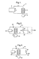
- Fig. 1 provides a schematic illustration of a typical active magnetic bearing.
- an electrical power supply 2 has a voltage V in order to supply a current i to a coil 3 such that through the magnetic field a target or rotor 4 is suspended with an air gap 5 between the coil and target/rotor 4.
- V voltage
- the target or rotor 4 can be subject to varying loads as required with the target/rotor 4 suspended by the magnetic field of the coil 3.
- a number of coils will be provided in order to support the target/rotor 4.
- the target/rotor 4 may be subject to differing loads or transient variations in load.
- the active magnetic bearing 1 will incorporate position sensors and a controller in order to determine variations in rotor position and in the air gap 5 such that an active response to such variations can be made.
- the rate at which the active magnetic bearing 1 can respond to a transient is determined, as indicated above, by the rate at which the current in the coils 3 can change with time, that is to say di/dt.
- this rate of change of current with time is limited by the voltage V of the normal electrical power supply 2 such that di/dt is less than or equal to voltage (V) divided by inductance (L).
- a short term storage device in the form of an electrical capacitor is provided to supply additional electrical power capacity during a target or shaft load transient.
- a normal electrical power supply 22 provides a supply voltage V to a coil 23 in order to constitute an active magnetic bearing relative to a target or rotor 24.
- a diode 20 is provided in the normal supply circuit from the electrical power supply 22 to the coil 23.
- a storage device 25 is provided with a switch 26 such that when a transient load variation occurs the switch 26 can be closed in order that a storage electric voltage VS is temporarily presented across the coil 23 whereby the transient current IT rises more quickly and is ultimately significantly greater and therefore capable of providing more robust support during the transient period.
- the diode 20 acts to ensure that the supply voltage VS is essentially presented across the coil 23 with the diode 20 therefore acting to prevent reverse current in the electrical power supply 22.
- the electrical current through the coil 23 immediately before, during and after a transient load variation is shown in Figure 3 .
- the electrical power supply 23 supplies a steady state current through the coil 23.
- the storage device 25 supplies a transient current through the coil 23 and then over time period C the electrical power supply 22 supplies a steady state current through the coil 23.
- a load transient occurs during time period B.
- the storage device 25 is an electric capacitor. This capacitor is charged to a voltage VS which is significantly greater than the normal power supply voltage V. In such circumstances as described, when a rapid transient change in the active magnetic bearing load occurs, the capacitor is discharged through the coil 23 to give a rapid change in the electrical current of the coil 23.
- some means (not shown) is required for determining that load transient. This means will typically take the form of positional sensors and a controller determining eccentricity of the target or rotor 24 indicative of load variation.
- the storage voltage VS in the storage device 25 can be many multiples of the normal supply voltage V in order to provide adequate capacity and to accommodate for the load transients described.
- VS may be orders of magnitude larger than V but will more typically be up to 10 times the normal supply voltage V.
- the storage device 25 in accordance with the present invention will be itself relatively short term rated to accommodate transient load variations, otherwise it would be more convenient simply to provide a broader normal supply voltage V range to accommodate such variations. In such circumstances there will generally be a regenerative time for the storage device 25 during which it will not be possible to fully provide the transient storage voltage VS and therefore transient current IT from a fully or partially discharged storage device 25.
- the regenerative time lag, or regenerative time is the time taken for a storage device 25 to recharge. There may be more than one transient load. This potential disadvantage may be overcome by providing a number of storage devices and as indicated in Fig.
- 125, 225 which can be appropriately controlled, switched and discharged as required in order to provide the transient current necessary for transient loading on the target or rotor 24.
- These additional storage devices 125, 225 may also be electrical capacitors or a battery or dc generator with a fly wheel storage device. In such circumstances, a large transient current IT can be maintained across the coil 23 for a more sustained period of time for a more long term transient loading on the target or rotor 24.
- the storage devices 25, eg the electrical capacitors are recharged to high voltages VS so that they are ready to be discharged again when there is another transient load.
- the storage devices 25, eg the electrical capacitors are charged by any suitable means and for example are supplied/charged by the electrical power supply 22 using a trickle charger using a voltage multiplier circuit.
- the storage device 25 is a small high voltage electrical power supply with a small amount of electrical energy.
- the present invention allows a larger storage voltage VS to be applied to the coil 23 than was possible with prior art arrangements of active magnetic bearings 1 described with respect to Fig. 1 . In such circumstances the transient current IT can be changed more rapidly with a consequently more rapid transient response within the active magnetic bearing 21 than also possible previously.
- the electrical discharge response from the storage device 25 can be important in terms of achieving the desired rapidity of response to transient loadings in the bearing 21.
- use of a transistor 37 or other type of electrical or optoelectrical device as the switch for a storage device 35 allows shaping of the inductance current to a coil 33 to achieve the most desirable active magnetic bearing 31 performance.
- the coil 33 acts relative to a target or rotor 34 normally utilising a supply voltage V from an electrical power supply 32.
- a diode 30 acts to prevent reverse current flow in the supply 32 whereby electrical discharge from the storage device 35 is presented across the coil 33 as required.
- the transistor 37 acting as a switch.
- the transistor 37 is controlled by a controller device (not shown) which will monitor the positional status and any other appropriate sensed parameters in order to determine the transient loading and therefore the appropriate response in terms of the transient electric current 17.
- the transistor 37 will be controlled through its gate 38 voltage in turn determined by the control device.
- the controller device may switch one of a number of alternative storage devices in order to present the storage voltage across the coil 33 and therefore induce a desired transient current in response to the transient load upon the bearing 31.
- the switch 26 or transistor 37 must enable rapid switching for electrical discharge in accordance with the present invention across the respective coil 23, 33 whereby that coil 23, 33 can respond to the transient loading on the target/rotor 24, 34.
Landscapes
- Engineering & Computer Science (AREA)
- General Engineering & Computer Science (AREA)
- Physics & Mathematics (AREA)
- Electromagnetism (AREA)
- Mechanical Engineering (AREA)
- Magnetic Bearings And Hydrostatic Bearings (AREA)
Description
- The present invention relates to magnetic bearings and more particularly to active controlled magnetic bearings subject to variable loading.
- Active magnetic bearings (AMB) typically comprise electrical coils of inductance L, a power supply of maximum voltage V, position sensors, a controller and a target or rotor supported by the bearing whose position is controlled. In short, through creation of a magnetic field, the target or rotor is magnetically supported by the magnetic field which in turn is created by the electrical inductance coils. Clearly, the load applied by the target or rotor is variable dependent upon operational status. In such circumstances the active magnetic bearing must respond to the variable load in order to support the target or rotor.
- The rate at which an active magnetic bearing can respond to a transient variation in load is determined by the rate at which electrical current i in the inductance coils can change with time. With prior active magnetic bearings this rate of change with time is limited by the available power supply voltage V and electrical coil inductance L in a relationship di/dt less than or equal to V/L. Nevertheless, it will be appreciated that these transients are relatively shortlived and therefore effective overrating of the power supply voltage V may lead to a cumbersome system.
- A magnetic bearing with the features of the preamble of claim 1 is known from
US 2003 187 321 A . This document discloses an axial blood pump with a magnetic bearing having control coils for stabilisation in the axial direction. The current in the control coils is adjusted by pulse width modulation. For normal operation a lower voltage is supplied to limit dissipation. To be able to achieve a quick reaction of the current control a higher voltage is additionally switched on only when a large difference between the desired current and the actual current is present. The energy is provided by implanted batteries. - In accordance with the present invention there is provided a magnetic bearing subject to variable load, the magnetic bearing comprising an inductance coil, an electrical power supply arranged to supply an electrical current to the inductance coil during normal loads, a storage device arranged to supply additional electrical current to the inductance coil during a load transient, wherein the storage device is an electrical capacitor having an electrical storage voltage significantly greater than the electrical supply voltage of the electrical power supply.
- Preferably a diode is provided between the inductance coil and the electrical power supply to prevent reverse current in the electrical power supply.
- Conveniently, a control switch is provided in order that, at appropriate times, the storage device is coupled to the inductance coil. Possibly, that control switch comprises a transistor or other electrical device or an optoelectrical device.
- Possibly, more than one storage device is provided. Typically, these storage devices allow for successive supplying of electrical current to the inductance coil within the regenerative time lag of the storage devices. Possibly, the storage devices allow for successive supplying of electrical current over a period of time to the inductance coil. Alternatively, the storage devices may allow through an appropriate switching regime for differing electrical storage voltage response dependent upon transient loading.
- Embodiments of the present invention will now be described by way of example only with reference to the accompanying drawings in which;
-
Fig. 1 is a schematic illustration of a typical active magnetic bearing; -
Fig. 2 is a schematic illustration of an active magnetic bearing in accordance with a first embodiment of the present invention; and, -
Fig. 3 is a graph showing electrical current through an inductance coil of the active magnetic bearing against time. -
Fig. 4 is a schematic illustration of an active magnetic bearing in accordance with a second embodiment of the present invention. -
Fig. 1 provides a schematic illustration of a typical active magnetic bearing. Thus, anelectrical power supply 2 has a voltage V in order to supply a current i to a coil 3 such that through the magnetic field a target orrotor 4 is suspended with anair gap 5 between the coil and target/rotor 4. In such circumstances the target orrotor 4 can be subject to varying loads as required with the target/rotor 4 suspended by the magnetic field of the coil 3. It will be understood normally a number of coils will be provided in order to support the target/rotor 4. - Clearly, in a normal operational situation the target/
rotor 4 may be subject to differing loads or transient variations in load. In such circumstances the active magnetic bearing 1 will incorporate position sensors and a controller in order to determine variations in rotor position and in theair gap 5 such that an active response to such variations can be made. The rate at which the active magnetic bearing 1 can respond to a transient is determined, as indicated above, by the rate at which the current in the coils 3 can change with time, that is to say di/dt. In the typical active magnetic bearing schematically depicted inFig. 1 , it will be noted that this rate of change of current with time is limited by the voltage V of the normalelectrical power supply 2 such that di/dt is less than or equal to voltage (V) divided by inductance (L). - In accordance with the present invention, a short term storage device in the form of an electrical capacitor is provided to supply additional electrical power capacity during a target or shaft load transient. Thus, in
Fig. 2 , a normalelectrical power supply 22 provides a supply voltage V to acoil 23 in order to constitute an active magnetic bearing relative to a target orrotor 24. Adiode 20 is provided in the normal supply circuit from theelectrical power supply 22 to thecoil 23. In accordance with the present invention, astorage device 25 is provided with aswitch 26 such that when a transient load variation occurs theswitch 26 can be closed in order that a storage electric voltage VS is temporarily presented across thecoil 23 whereby the transient current IT rises more quickly and is ultimately significantly greater and therefore capable of providing more robust support during the transient period. Thediode 20 acts to ensure that the supply voltage VS is essentially presented across thecoil 23 with thediode 20 therefore acting to prevent reverse current in theelectrical power supply 22. - The electrical current through the
coil 23 immediately before, during and after a transient load variation is shown inFigure 3 . Over time period A theelectrical power supply 23 supplies a steady state current through thecoil 23. During time period B thestorage device 25 supplies a transient current through thecoil 23 and then over time period C theelectrical power supply 22 supplies a steady state current through thecoil 23. A load transient occurs during time period B. - As depicted, the
storage device 25 is an electric capacitor. This capacitor is charged to a voltage VS which is significantly greater than the normal power supply voltage V. In such circumstances as described, when a rapid transient change in the active magnetic bearing load occurs, the capacitor is discharged through thecoil 23 to give a rapid change in the electrical current of thecoil 23. Clearly, some means (not shown) is required for determining that load transient. This means will typically take the form of positional sensors and a controller determining eccentricity of the target orrotor 24 indicative of load variation. - Generally, within the electrical and heat capacity of the
coil 23, the storage voltage VS in thestorage device 25 can be many multiples of the normal supply voltage V in order to provide adequate capacity and to accommodate for the load transients described. Thus, VS may be orders of magnitude larger than V but will more typically be up to 10 times the normal supply voltage V. - By implication the
storage device 25 in accordance with the present invention will be itself relatively short term rated to accommodate transient load variations, otherwise it would be more convenient simply to provide a broader normal supply voltage V range to accommodate such variations. In such circumstances there will generally be a regenerative time for thestorage device 25 during which it will not be possible to fully provide the transient storage voltage VS and therefore transient current IT from a fully or partially dischargedstorage device 25. The regenerative time lag, or regenerative time, is the time taken for astorage device 25 to recharge. There may be more than one transient load. This potential disadvantage may be overcome by providing a number of storage devices and as indicated inFig. 2 bybroken lines rotor 24. Theseadditional storage devices coil 23 for a more sustained period of time for a more long term transient loading on the target orrotor 24. It will also be understood by mixing different types of storage device, that is to say combinations of electrical capacitor, batteries and dc generators, it may be possible to achieve different speeds of transient response depending upon the detected transient loading placed upon the activemagnetic bearing 21. Nevertheless, it is more rapid response which is a core desirable feature of the present invention, and as indicated previously this will depend upon the high value of the storage voltage VS in order to induce the significant transient current IT quickly to meet the transient loading on the activemagnetic bearing 21. - The
storage devices 25, eg the electrical capacitors, are recharged to high voltages VS so that they are ready to be discharged again when there is another transient load. Thestorage devices 25, eg the electrical capacitors are charged by any suitable means and for example are supplied/charged by theelectrical power supply 22 using a trickle charger using a voltage multiplier circuit. Thestorage device 25 is a small high voltage electrical power supply with a small amount of electrical energy. - The present invention allows a larger storage voltage VS to be applied to the
coil 23 than was possible with prior art arrangements of active magnetic bearings 1 described with respect toFig. 1 . In such circumstances the transient current IT can be changed more rapidly with a consequently more rapid transient response within the active magnetic bearing 21 than also possible previously. - As indicated above, the electrical discharge response from the
storage device 25 can be important in terms of achieving the desired rapidity of response to transient loadings in thebearing 21. As illustrated inFig. 4 , use of atransistor 37 or other type of electrical or optoelectrical device as the switch for astorage device 35 allows shaping of the inductance current to acoil 33 to achieve the most desirable active magnetic bearing 31 performance. As previously thecoil 33 acts relative to a target orrotor 34 normally utilising a supply voltage V from anelectrical power supply 32. Adiode 30 acts to prevent reverse current flow in thesupply 32 whereby electrical discharge from thestorage device 35 is presented across thecoil 33 as required. In such circumstances when the target orrotor 34 is subject to a transient loading, additional current can be more rapidly injected into thecoil 33 from thestorage device 35 under the control of thetransistor 37 acting as a switch. In turn thetransistor 37 is controlled by a controller device (not shown) which will monitor the positional status and any other appropriate sensed parameters in order to determine the transient loading and therefore the appropriate response in terms of the transient electric current 17. Typically, thetransistor 37 will be controlled through itsgate 38 voltage in turn determined by the control device. - The controller device may switch one of a number of alternative storage devices in order to present the storage voltage across the
coil 33 and therefore induce a desired transient current in response to the transient load upon thebearing 31. Inherently, theswitch 26 ortransistor 37 must enable rapid switching for electrical discharge in accordance with the present invention across therespective coil coil rotor - As described above if a more sustained transient electrical current is required from the storage means in accordance with the present invention then devices will be sequentially activated in order to present their respective storage voltage (VS) across the coils in succession. By such an approach it will be understood that high voltage spikes and therefore high inductance currents will flow through the coils, but as a result of the switches and control system there will be a relative smoothing of the sub transitions between the respective storage devices in order to sustain the higher electrical current through the coil in order to accommodate the variable loading upon the target/rotor as required. Nevertheless, it is not envisaged that the storage devices will for extended periods of time present electrical current through the coil and therefore replace the normal supply voltage V presented across the coil by the electrical power supplies 22, 32.
Claims (9)
- A magnetic bearing (21) subject to variable load, the magnetic bearing (21,31) comprising:an inductance coil (23,33)an electrical power supply (22,32) arranged to supply an electrical current to the inductance coil (23,33) during normal loads, anda storage device (25,35,125,225) being arranged to supply additional electrical current to the inductance coil (23,33) during a load transient,characterised in that the storage device (25) is an electrical capacitor having an electrical storage voltage (VS) significantly greater than the electrical supply voltage (V) of the electrical power supply (22,32).
- A bearing as claimed in claim 1, wherein a diode (20,30) is provided between the inductance coil (23,33) and the electrical power supply (22,32) to prevent reverse current in the electrical power supply.
- A bearing as claimed in claim 1 or claim 2, wherein a control switch (26) is provided which can be closed when a transient load variation occurs in order to couple the storage device (25) to the inductance coil (23).
- A bearing as claimed in claim 3, wherein the control switch (26) comprises a transistor (37), other electrical device or optoelectrical device.
- A bearing as claimed in any preceding claim, wherein one or more additional storage device (125,225) is provided.
- A bearing as claimed in claim 5, wherein the storage device (25) and one or more additional storage device (125,225) allow for successive supplying of electrical current to the inductance coil (23) within the regenerative time lag of the storage device (25).
- A bearing as claimed in claim 5 or claim 6, wherein the storage devices (25,125,225) allow for successive supplying of electrical current over a period of time to the inductance coil (23).
- A bearing as claimed in any one of claims 5 to 7, wherein the additional storage device (125,225) is a capacitor, a battery, or a dc generator with a fly wheel.
- A rotor assembly including a magnetic bearing as claimed in any of claims 1 to 8.
Applications Claiming Priority (2)
| Application Number | Priority Date | Filing Date | Title |
|---|---|---|---|
| GB0410168 | 2004-05-06 | ||
| GBGB0410168.9A GB0410168D0 (en) | 2004-05-06 | 2004-05-06 | A magnetic bearing |
Publications (3)
| Publication Number | Publication Date |
|---|---|
| EP1594211A2 EP1594211A2 (en) | 2005-11-09 |
| EP1594211A3 EP1594211A3 (en) | 2006-01-11 |
| EP1594211B1 true EP1594211B1 (en) | 2012-08-22 |
Family
ID=32482815
Family Applications (1)
| Application Number | Title | Priority Date | Filing Date |
|---|---|---|---|
| EP05251842A Expired - Lifetime EP1594211B1 (en) | 2004-05-06 | 2005-03-24 | Electromagnetic bearing with two power sources having distinct voltage; Demagnetising permanent magnets upon failure in an electrical machine |
Country Status (3)
| Country | Link |
|---|---|
| US (2) | US7138739B2 (en) |
| EP (1) | EP1594211B1 (en) |
| GB (1) | GB0410168D0 (en) |
Families Citing this family (3)
| Publication number | Priority date | Publication date | Assignee | Title |
|---|---|---|---|---|
| US20080156219A1 (en) * | 2006-06-28 | 2008-07-03 | Voss Donald E | Method and apparatus for destroying or incapacitating improvised explosives, mines and other systems containing electronics or explosives |
| WO2009012258A1 (en) * | 2007-07-16 | 2009-01-22 | University Of Virginia Patent Foundation | Self sensing integrated system and method for determining the position of a shaft in a magnetic bearing |
| EP3327299A1 (en) * | 2016-11-23 | 2018-05-30 | Forsnetics AB | Fail-safe system for the controlled discharge of an electromagnet of a thrust magnetic bearing |
Family Cites Families (13)
| Publication number | Priority date | Publication date | Assignee | Title |
|---|---|---|---|---|
| GB1228004A (en) * | 1968-05-27 | 1971-04-15 | ||
| JP2799886B2 (en) * | 1989-09-11 | 1998-09-21 | 株式会社セコー技研 | Energization control device for inductance load |
| DE69127808T2 (en) * | 1990-11-22 | 1998-01-29 | Sekoh Giken Kk | CURRENT CONTROLLER FOR INDUCTIVE LOAD |
| US5262692A (en) * | 1992-04-13 | 1993-11-16 | Center For Innovative Technology | Variable voltage switched current control |
| JPH05312214A (en) | 1992-05-12 | 1993-11-22 | Daikin Ind Ltd | Magnetic bearing device and magnetic bearing control method |
| JP3519771B2 (en) * | 1994-02-28 | 2004-04-19 | Ntn株式会社 | Magnetic bearing device |
| US5528445A (en) * | 1994-09-23 | 1996-06-18 | General Electric Company | Automatic fault current protection for a locomotive propulsion system |
| US5574346A (en) * | 1995-05-15 | 1996-11-12 | Delco Electronics Corporation | On and off state fault detection circuit for a multi-phase brushed or brushless DC motor |
| GB2303412B (en) * | 1995-07-14 | 1999-08-11 | Glacier Metal Co Ltd | Electromagnetic bearing |
| US5990590A (en) * | 1996-09-10 | 1999-11-23 | Precise Power Corporation | Versatile AC dynamo-electric machine |
| FR2817088B1 (en) * | 2000-11-17 | 2003-02-21 | Mecanique Magnetique Sa | AXIAL MAGNETIC ROTARY ROTATING MACHINE INTEGRATING A CURRENT GENERATOR |
| DE10123138B4 (en) * | 2001-04-30 | 2007-09-27 | Berlin Heart Ag | Method for position control of a permanently magnetically mounted rotating component |
| JP2004286045A (en) * | 2003-03-19 | 2004-10-14 | Boc Edwards Kk | Magnetic bearing device, and pump unit mounting the same magnetic bearing device |
-
2004
- 2004-05-06 GB GBGB0410168.9A patent/GB0410168D0/en not_active Ceased
-
2005
- 2005-03-24 EP EP05251842A patent/EP1594211B1/en not_active Expired - Lifetime
- 2005-03-24 US US11/088,972 patent/US7138739B2/en not_active Expired - Fee Related
-
2006
- 2006-09-29 US US11/529,505 patent/US7215054B2/en not_active Expired - Fee Related
Also Published As
| Publication number | Publication date |
|---|---|
| EP1594211A3 (en) | 2006-01-11 |
| US7215054B2 (en) | 2007-05-08 |
| US7138739B2 (en) | 2006-11-21 |
| EP1594211A2 (en) | 2005-11-09 |
| US20050248226A1 (en) | 2005-11-10 |
| US20070018518A1 (en) | 2007-01-25 |
| GB0410168D0 (en) | 2004-06-09 |
Similar Documents
| Publication | Publication Date | Title |
|---|---|---|
| US11458852B2 (en) | DC-DC converter control | |
| JP6602791B2 (en) | Engine start and battery support module | |
| EP0901218B1 (en) | Turbogenerator/motor controller | |
| Gurumurthy et al. | Optimal energy harvesting from a high‐speed brushless DC generator‐based flywheel energy storage system | |
| JP2003516707A (en) | Switched reluctance generator and method of controlling the generator | |
| US10976762B2 (en) | Control of an electrical power system responsive to sensing a ground fault | |
| JP2008535468A (en) | Electric vehicle drive system and drive system control method | |
| US8294412B2 (en) | Method for controlling a rotary electric machine in case of load shedding and corresponding power control module | |
| JP5318238B2 (en) | Power management apparatus, power management method, and power management system | |
| US7138739B2 (en) | Magnetic bearing | |
| KR100737654B1 (en) | Power supplying apparatus and power supplying method | |
| US20080042611A1 (en) | Self-excitation of switched reluctance generators during load bus faults | |
| JP3938331B2 (en) | Magnetic bearing generator motor | |
| EP2924866B1 (en) | An electrical power converter for a working machine | |
| KR101322514B1 (en) | Controller of permanent magnet generator and permanent magnet generator with the controller | |
| KR102376784B1 (en) | A device and a method for controlling an electromechanical power transmission chain | |
| JP2002300760A (en) | Electric motor / generator and power storage / voltage control method thereof | |
| US9350280B2 (en) | Method for operating a power supply unit for an electrical system of a motor vehicle | |
| KR100742715B1 (en) | Permanent magnet generator equipped with pfc | |
| JP4517775B2 (en) | Control method of flywheel type uninterruptible power supply and uninterruptible power supply using the same | |
| KR101916796B1 (en) | Alternator for vehicle and operationg method thereof | |
| WO2002021674A1 (en) | Power supply for high speed motor | |
| JP2012157196A (en) | Motor running-in method and motor drive device | |
| WO2018138403A1 (en) | Method for controlling electrical input power of elevator, elevator control unit, computer program product, and elevator utilizing the method thereof | |
| CN117477864A (en) | Bearingless motor control method, control circuit and bearingless motor |
Legal Events
| Date | Code | Title | Description |
|---|---|---|---|
| PUAI | Public reference made under article 153(3) epc to a published international application that has entered the european phase |
Free format text: ORIGINAL CODE: 0009012 |
|
| AK | Designated contracting states |
Kind code of ref document: A2 Designated state(s): AT BE BG CH CY CZ DE DK EE ES FI FR GB GR HU IE IS IT LI LT LU MC NL PL PT RO SE SI SK TR |
|
| AX | Request for extension of the european patent |
Extension state: AL BA HR LV MK YU |
|
| PUAL | Search report despatched |
Free format text: ORIGINAL CODE: 0009013 |
|
| AK | Designated contracting states |
Kind code of ref document: A3 Designated state(s): AT BE BG CH CY CZ DE DK EE ES FI FR GB GR HU IE IS IT LI LT LU MC NL PL PT RO SE SI SK TR |
|
| AX | Request for extension of the european patent |
Extension state: AL BA HR LV MK YU |
|
| 17P | Request for examination filed |
Effective date: 20060127 |
|
| AKX | Designation fees paid |
Designated state(s): DE FR GB |
|
| 17Q | First examination report despatched |
Effective date: 20081205 |
|
| GRAP | Despatch of communication of intention to grant a patent |
Free format text: ORIGINAL CODE: EPIDOSNIGR1 |
|
| GRAS | Grant fee paid |
Free format text: ORIGINAL CODE: EPIDOSNIGR3 |
|
| GRAA | (expected) grant |
Free format text: ORIGINAL CODE: 0009210 |
|
| AK | Designated contracting states |
Kind code of ref document: B1 Designated state(s): DE FR GB |
|
| REG | Reference to a national code |
Ref country code: GB Ref legal event code: FG4D |
|
| REG | Reference to a national code |
Ref country code: DE Ref legal event code: R096 Ref document number: 602005035738 Country of ref document: DE Effective date: 20121018 |
|
| PLBE | No opposition filed within time limit |
Free format text: ORIGINAL CODE: 0009261 |
|
| STAA | Information on the status of an ep patent application or granted ep patent |
Free format text: STATUS: NO OPPOSITION FILED WITHIN TIME LIMIT |
|
| 26N | No opposition filed |
Effective date: 20130523 |
|
| REG | Reference to a national code |
Ref country code: DE Ref legal event code: R097 Ref document number: 602005035738 Country of ref document: DE Effective date: 20130523 |
|
| REG | Reference to a national code |
Ref country code: FR Ref legal event code: PLFP Year of fee payment: 11 |
|
| REG | Reference to a national code |
Ref country code: FR Ref legal event code: PLFP Year of fee payment: 12 |
|
| PGFP | Annual fee paid to national office [announced via postgrant information from national office to epo] |
Ref country code: FR Payment date: 20160328 Year of fee payment: 12 Ref country code: GB Payment date: 20160329 Year of fee payment: 12 |
|
| PGFP | Annual fee paid to national office [announced via postgrant information from national office to epo] |
Ref country code: DE Payment date: 20160331 Year of fee payment: 12 |
|
| REG | Reference to a national code |
Ref country code: DE Ref legal event code: R119 Ref document number: 602005035738 Country of ref document: DE |
|
| GBPC | Gb: european patent ceased through non-payment of renewal fee |
Effective date: 20170324 |
|
| REG | Reference to a national code |
Ref country code: FR Ref legal event code: ST Effective date: 20171130 |
|
| PG25 | Lapsed in a contracting state [announced via postgrant information from national office to epo] |
Ref country code: DE Free format text: LAPSE BECAUSE OF NON-PAYMENT OF DUE FEES Effective date: 20171003 Ref country code: FR Free format text: LAPSE BECAUSE OF NON-PAYMENT OF DUE FEES Effective date: 20170331 |
|
| PG25 | Lapsed in a contracting state [announced via postgrant information from national office to epo] |
Ref country code: GB Free format text: LAPSE BECAUSE OF NON-PAYMENT OF DUE FEES Effective date: 20170324 |