EP1593830B1 - Engine control device for construction machine - Google Patents
Engine control device for construction machine Download PDFInfo
- Publication number
- EP1593830B1 EP1593830B1 EP04705902.7A EP04705902A EP1593830B1 EP 1593830 B1 EP1593830 B1 EP 1593830B1 EP 04705902 A EP04705902 A EP 04705902A EP 1593830 B1 EP1593830 B1 EP 1593830B1
- Authority
- EP
- European Patent Office
- Prior art keywords
- control
- automatic
- engine
- automatic deceleration
- automatic stop
- Prior art date
- Legal status (The legal status is an assumption and is not a legal conclusion. Google has not performed a legal analysis and makes no representation as to the accuracy of the status listed.)
- Expired - Lifetime
Links
- 238000010276 construction Methods 0.000 title claims description 7
- 238000001816 cooling Methods 0.000 description 5
- 239000000446 fuel Substances 0.000 description 3
- 238000000034 method Methods 0.000 description 3
- 238000010586 diagram Methods 0.000 description 2
- 230000004397 blinking Effects 0.000 description 1
- 239000006227 byproduct Substances 0.000 description 1
- 230000015556 catabolic process Effects 0.000 description 1
- 230000003197 catalytic effect Effects 0.000 description 1
- 238000002485 combustion reaction Methods 0.000 description 1
- 239000010763 heavy fuel oil Substances 0.000 description 1
- 238000007726 management method Methods 0.000 description 1
- 230000001681 protective effect Effects 0.000 description 1
- 238000010926 purge Methods 0.000 description 1
Images


Classifications
-
- F—MECHANICAL ENGINEERING; LIGHTING; HEATING; WEAPONS; BLASTING
- F02—COMBUSTION ENGINES; HOT-GAS OR COMBUSTION-PRODUCT ENGINE PLANTS
- F02D—CONTROLLING COMBUSTION ENGINES
- F02D41/00—Electrical control of supply of combustible mixture or its constituents
- F02D41/02—Circuit arrangements for generating control signals
- F02D41/04—Introducing corrections for particular operating conditions
- F02D41/12—Introducing corrections for particular operating conditions for deceleration
-
- E—FIXED CONSTRUCTIONS
- E02—HYDRAULIC ENGINEERING; FOUNDATIONS; SOIL SHIFTING
- E02F—DREDGING; SOIL-SHIFTING
- E02F9/00—Component parts of dredgers or soil-shifting machines, not restricted to one of the kinds covered by groups E02F3/00 - E02F7/00
- E02F9/20—Drives; Control devices
- E02F9/2058—Electric or electro-mechanical or mechanical control devices of vehicle sub-units
- E02F9/2062—Control of propulsion units
-
- F—MECHANICAL ENGINEERING; LIGHTING; HEATING; WEAPONS; BLASTING
- F02—COMBUSTION ENGINES; HOT-GAS OR COMBUSTION-PRODUCT ENGINE PLANTS
- F02D—CONTROLLING COMBUSTION ENGINES
- F02D17/00—Controlling engines by cutting out individual cylinders; Rendering engines inoperative or idling
- F02D17/04—Controlling engines by cutting out individual cylinders; Rendering engines inoperative or idling rendering engines inoperative or idling, e.g. caused by abnormal conditions
-
- F—MECHANICAL ENGINEERING; LIGHTING; HEATING; WEAPONS; BLASTING
- F02—COMBUSTION ENGINES; HOT-GAS OR COMBUSTION-PRODUCT ENGINE PLANTS
- F02D—CONTROLLING COMBUSTION ENGINES
- F02D41/00—Electrical control of supply of combustible mixture or its constituents
- F02D41/02—Circuit arrangements for generating control signals
- F02D41/04—Introducing corrections for particular operating conditions
- F02D41/042—Introducing corrections for particular operating conditions for stopping the engine
-
- F—MECHANICAL ENGINEERING; LIGHTING; HEATING; WEAPONS; BLASTING
- F02—COMBUSTION ENGINES; HOT-GAS OR COMBUSTION-PRODUCT ENGINE PLANTS
- F02D—CONTROLLING COMBUSTION ENGINES
- F02D31/00—Use of speed-sensing governors to control combustion engines, not otherwise provided for
- F02D31/001—Electric control of rotation speed
-
- F—MECHANICAL ENGINEERING; LIGHTING; HEATING; WEAPONS; BLASTING
- F02—COMBUSTION ENGINES; HOT-GAS OR COMBUSTION-PRODUCT ENGINE PLANTS
- F02D—CONTROLLING COMBUSTION ENGINES
- F02D41/00—Electrical control of supply of combustible mixture or its constituents
- F02D41/02—Circuit arrangements for generating control signals
- F02D41/021—Introducing corrections for particular conditions exterior to the engine
-
- F—MECHANICAL ENGINEERING; LIGHTING; HEATING; WEAPONS; BLASTING
- F02—COMBUSTION ENGINES; HOT-GAS OR COMBUSTION-PRODUCT ENGINE PLANTS
- F02N—STARTING OF COMBUSTION ENGINES; STARTING AIDS FOR SUCH ENGINES, NOT OTHERWISE PROVIDED FOR
- F02N11/00—Starting of engines by means of electric motors
- F02N11/08—Circuits specially adapted for starting of engines
- F02N11/0814—Circuits specially adapted for starting of engines comprising means for controlling automatic idle-start-stop
- F02N11/0818—Conditions for starting or stopping the engine or for deactivating the idle-start-stop mode
- F02N11/0833—Vehicle conditions
-
- F—MECHANICAL ENGINEERING; LIGHTING; HEATING; WEAPONS; BLASTING
- F02—COMBUSTION ENGINES; HOT-GAS OR COMBUSTION-PRODUCT ENGINE PLANTS
- F02N—STARTING OF COMBUSTION ENGINES; STARTING AIDS FOR SUCH ENGINES, NOT OTHERWISE PROVIDED FOR
- F02N2200/00—Parameters used for control of starting apparatus
- F02N2200/08—Parameters used for control of starting apparatus said parameters being related to the vehicle or its components
- F02N2200/0815—Vehicle door sensors
Definitions
- the present invention relates to an engine control device for a construction machine in which an engine is automatically stopped (automatic stop) at a non-operation time.
- a construction machine including an automatic stop function for automatically stopping an engine when predetermined automatic stop conditions for example, a gate lever for opening and closing a gateway to a cabin is opened and an operating lever for operating a work actuator is in non-operation
- predetermined automatic stop conditions for example, a gate lever for opening and closing a gateway to a cabin is opened and an operating lever for operating a work actuator is in non-operation
- US 2002/165660 describes a method and system to control engine shutdown in a hybrid electric vehicle (HEV).
- HEV hybrid electric vehicle
- the invention allows for reduced tailpipe emissions during the many engine shutdowns and subsequent restarts during the course of an HEV drive cycle and reduced evaporative emissions during an HEV "soak" (inactive) period.
- the engine shutdown routine can ramp off fuel injectors, control engine torque (via electronic throttle control), control engine speed, stop spark delivery by disabling the ignition system, stop purge vapour flow by closing a vapour management valve (VMV), stop exhaust gas recirculation (EGR) flow by closing an EGR valve, and flush the intake manifold of residual fuel (vapour and puddles) into the combustion chamber to be combusted.
- VMV vapour management valve
- EGR exhaust gas recirculation
- JP 63/105249 discloses means which enable an engine to perform a cooling down procedure with no trouble given to an operator, by stopping the engine after a low speed operation is automatically performed for a predetermined time in accordance with the action of turning off a key switch.
- a key switch controls the engine being turned off, and if a stopping instruction of an engine is generated, a key switch 'off' signal is output to the second target engine speed setting means from a detecting means.
- a signal of target engine speed, sufficiently low for performing low speed operation is output to a minimum value selecting means from the second target engine speed setting means and compared with a signal of target engine speed output from the first target engine speed setting means, and the minimum value selecting means selects a signal of the lower target engine speed to be output to a governor control means.
- the engine being driven in low speed operation by driving a governor, performs the cooling down, and after the predetermined time, a signal is output to a fuel cut-off means from a timer means, and the engine is stopped.
- Reference numeral 1 denotes an engine as a power source.
- This engine 1 is provided with a governor controller 2.
- a control of stop/speed (rotational number or number of rotation) of the engine 1 is performed based on signals from a controller 3 as control means and an engine throttle (speed setter).
- the controller 3 includes an engine controller 4, which sends signals of commands of stop/speed to the governor controller 2, an automatic deceleration command unit 5, which sends a command of starting an automatic deceleration control for reducing an engine speed to a low speed of a predetermined value or less so that cooling down of the engine is performed to this engine controller 4, an automatic stop command unit 6, which sends a command of starting an automatic stop control to the engine controller 4 and a selection determining unit 7.
- the selection determining unit 7 determines effectiveness/ineffectiveness of the automatic deceleration control and the automatic stop control based on the ON/OFF operation of both first and second switches 9 and 10, which constitute selection means 8. This determination condition is as follows.
- automatic deceleration command unit 5 is input a signal (automatic deceleration condition signal), which shows that a predetermined starting condition of automatic deceleration control is met
- automatic stop command unit 6 is input a signal (automatic stop condition signal), which shows that a predetermined starting condition of automatic stop control is set.
- a signal for commanding the start of a control (automatic deceleration or automatic stop control) determined to be effective is sent from both command units 5 and 6 to the engine controller 4 based on the condition signal and the determination signal from the above-mentioned selection determining unit 7.
- the automatic deceleration condition includes for example a condition in which a remote control valve (not shown), which controls an operation of a working hydraulic actuator is not continuously operated for a fixed period (non-operation). This condition is detected by a pressure sensor provided in the remote control valve and sent to the automatic deceleration command unit 5.
- the automatic stop condition includes for example a condition in which a gate lever for opening and closing a gateway of a cabin is opened. This condition is detected by a switch, which is ON/OFF operated in synchronization with a movement of the gate lever and sent to the automatic stop command unit 6.
- the engine operation detecting means 11 a sensor for detecting a speed of the engine 1, a sensor for detecting voltage or current of a generator driven by the engine 1, and a sensor for detecting a pressure of a hydraulic pump as an actuator driving source are used.
- the automatic deceleration or automatic stop control is performed on the premise that it is detected that the engine 1 is in operation by the engine operation detecting means 11.
- Step S1 It is determined whether the automatic stop control is ineffective or not at the starting of control (Step S1). If it is determined to be ineffective, the processing flow advances to Step S2, and if it is determined to be effective the processing flow advances to Step S6.
- Step S2 it is further determined whether the automatic deceleration control is effective or ineffective. If it is determined to be NO (effective), it is determined whether or not the automatic deceleration is met in Step S3.
- Step S3 In a case of NO (not met) in Step S3, and in a case of YES (ineffective) in Step S2, the engine speed is maintained to a speed (predetermined speed) set by an engine throttle in Step S4. In the meanwhile, in a case of YES (automatic deceleration condition is met) in Step S3, the engine speed is reduced to a predetermined low standby speed in Step S5.
- Step S1 it is determined whether or not the engine is in operation in Step S6, and whether or not the automatic stop condition is met in Step S7. In a case of NO in Steps S6 and S7, the processing flow returns to Step S2.
- Step S7 the processing flow advances to Step S8 so that it is determined whether or not a predetermined period T as a period required for cooling down has passed.
- a predetermined period T as a period required for cooling down has passed.
- NO prior to the passage of period T
- Step S9 the engine speed is maintained to the standby speed (Step S5) and after the passage the engine 1 is automatically stopped (Step S9).
- Step S8 the processing flow advances to Step S9 so that the engine 1 is automatically stopped.
- the effectiveness/ineffectiveness of automatic deceleration control is selected by selection means 8.
- the automatic deceleration control is operated in accordance with this selection, or it becomes ineffective.
- Step S7 an automatic deceleration control (forced control) is performed by Steps S8 and S5 prior to the automatic stop control within a fixed period T irrespective of the selection of effectiveness/ineffectiveness of the automatic deceleration control, and the engine speed is reduced so that cooling down of the engine 1 is carried out. Accordingly, there is no fear that the engine 1 is suddenly stopped with high speed more than a predetermined value, thereby leading to a breakdown of devices such as the engine 1 and the like. Namely, this engine control device can ensure protective action on devices, which is the predetermined object of the device.
- the automatic deceleration control forcibly is operated prior to automatic stop.
- the device is shifted to an operation state, which is against the operator's intention to make the automatic deceleration ineffective, and the operator can misunderstand that the device is in trouble.
- a rotary selection switch 12 is used as selection means.
- a first position (first state) (a), where both automatic deceleration control and automatic stop control become effective, a second position (second state) (b), where only the automatic deceleration control becomes effective, and a third position (third state) (c), where both the automatic deceleration control and the automatic stop control become ineffective are set in the switch 12.
- indications 13 indicating respective selection items (for example, as shown in Fig. 3 , characters of "automatic deceleration + automatic stop" at the first position (a), "automatic deceleration” at the second position (b), and "OFF” at the third position (c)).
- the automatic deceleration control is always operated prior to the automatic stop control as in the first embodiment, a predetermined object to protect devices such as an engine can be reliably attained.
- an automatic deceleration control force control
- an automatic stop control for a fixed period irrespective of a selection of effectiveness/ineffectiveness of the automatic deceleration so that an engine speed is reduced.
- the selection state by selection means there is no state where only the automatic stop control becomes effective and effectiveness/ineffectiveness of the automatic stop control can be selected only in pairs with the automatic deceleration control.
- the selection is effected after the operator recognized that the automatic deceleration control is operated. Therefore, even if the automatic deceleration control is operated prior to automatic stop, the operator cannot misunderstand it as a trouble.
Landscapes
- Engineering & Computer Science (AREA)
- General Engineering & Computer Science (AREA)
- Chemical & Material Sciences (AREA)
- Combustion & Propulsion (AREA)
- Mechanical Engineering (AREA)
- Mining & Mineral Resources (AREA)
- Civil Engineering (AREA)
- Structural Engineering (AREA)
- Control Of Vehicle Engines Or Engines For Specific Uses (AREA)
- Output Control And Ontrol Of Special Type Engine (AREA)
- Electrical Control Of Air Or Fuel Supplied To Internal-Combustion Engine (AREA)
- Combined Controls Of Internal Combustion Engines (AREA)
Description
- The present invention relates to an engine control device for a construction machine in which an engine is automatically stopped (automatic stop) at a non-operation time.
- A construction machine including an automatic stop function for automatically stopping an engine when predetermined automatic stop conditions (for example, a gate lever for opening and closing a gateway to a cabin is opened and an operating lever for operating a work actuator is in non-operation) are met has been disclosed in Japanese Patent Laid-Open Nos.
2000-96627 2001-41069 - Further, a technique in which when fixed conditions are met (for example, an operating lever for operating a work actuator is not continuously operated for a fixed period) a speed of an engine is automatically reduced to save fuel or the like, so called an automatic deceleration (automatic speed reduction) function is performed, has been generally known.
- In a case where the above-mentioned automatic deceleration function is combined with the above-mentioned automatic stop function so that effectiveness/ineffectiveness of both functions can be selected, when automatic stop conditions are met while ineffectiveness of the automatic deceleration function is selected using the automatic stop function, a situation in which the only automatic stop function serves so that an engine is stopped while keeping high engine speed, is generated. Accordingly, the engine and other devices cannot be protected.
- It is an object of the present invention to provide an engine control device for a construction machine, which can reliably protect an engine and other devices even in a state where the ineffectiveness of the automatic deceleration function is selected.
-
US 2002/165660 describes a method and system to control engine shutdown in a hybrid electric vehicle (HEV). The invention allows for reduced tailpipe emissions during the many engine shutdowns and subsequent restarts during the course of an HEV drive cycle and reduced evaporative emissions during an HEV "soak" (inactive) period. The engine shutdown routine can ramp off fuel injectors, control engine torque (via electronic throttle control), control engine speed, stop spark delivery by disabling the ignition system, stop purge vapour flow by closing a vapour management valve (VMV), stop exhaust gas recirculation (EGR) flow by closing an EGR valve, and flush the intake manifold of residual fuel (vapour and puddles) into the combustion chamber to be combusted. The resulting exhaust gas by-products are then converted in the catalytic converter. -
JP 63/105249 - To solve the above-mentioned problems, the present invention adopted the following configurations described by
claims -
-
Fig. 1 is a block diagram showing a first embodiment of the present invention; and -
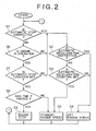
Fig. 2 is a flow chart for explaining an action of the first embodiment; -
Fig. 3 is a block diagram showing a second embodiment of the present invention. -
Reference numeral 1 denotes an engine as a power source. Thisengine 1 is provided with agovernor controller 2. By thisgovernor controller 2, a control of stop/speed (rotational number or number of rotation) of theengine 1 is performed based on signals from acontroller 3 as control means and an engine throttle (speed setter). - The
controller 3 includes anengine controller 4, which sends signals of commands of stop/speed to thegovernor controller 2, an automaticdeceleration command unit 5, which sends a command of starting an automatic deceleration control for reducing an engine speed to a low speed of a predetermined value or less so that cooling down of the engine is performed to thisengine controller 4, an automaticstop command unit 6, which sends a command of starting an automatic stop control to theengine controller 4 and aselection determining unit 7. - The
selection determining unit 7 determines effectiveness/ineffectiveness of the automatic deceleration control and the automatic stop control based on the ON/OFF operation of both first andsecond switches - When the
first switch 9 is turned ON, it is determined that the effectiveness of the automatic deceleration control is selected, and when the switch is turned OFF it is determined that the ineffectiveness of the automatic deceleration control is selected. - When the
first switch 10 is turned ON, it is determined that the effectiveness of the automatic stop control is selected and when the switch is turned OFF it is determined that the ineffectiveness of the automatic stop control is selected. - These determination results are sent to the automatic
deceleration command unit 5 and the automaticstop command unit 6. - Further to the automatic
deceleration command unit 5 is input a signal (automatic deceleration condition signal), which shows that a predetermined starting condition of automatic deceleration control is met, and to the automaticstop command unit 6 is input a signal (automatic stop condition signal), which shows that a predetermined starting condition of automatic stop control is set. A signal for commanding the start of a control (automatic deceleration or automatic stop control) determined to be effective is sent from bothcommand units engine controller 4 based on the condition signal and the determination signal from the above-mentionedselection determining unit 7. - It is noted that the automatic deceleration condition includes for example a condition in which a remote control valve (not shown), which controls an operation of a working hydraulic actuator is not continuously operated for a fixed period (non-operation). This condition is detected by a pressure sensor provided in the remote control valve and sent to the automatic
deceleration command unit 5. - On the other hand, the automatic stop condition includes for example a condition in which a gate lever for opening and closing a gateway of a cabin is opened. This condition is detected by a switch, which is ON/OFF operated in synchronization with a movement of the gate lever and sent to the automatic
stop command unit 6. - It is noted that when a machine of a canopy structure having no cabin has alternative means for the above-mentioned gate lever, the operation of this alternative means becomes an automatic stop condition. For example, when an operating lever box provided with an operating lever is liftable and lowerable and the machine has a configuration in which the lever box is lowered at the seating of an operator, a condition in which the operating lever box is lifted (opened) becomes an automatic stop condition.
- Further, to the
engine controller 4 is sent a signal from engine operation detecting means 11 in addition to command signals from bothcommand units - As the engine operation detecting means 11 a sensor for detecting a speed of the
engine 1, a sensor for detecting voltage or current of a generator driven by theengine 1, and a sensor for detecting a pressure of a hydraulic pump as an actuator driving source are used. The automatic deceleration or automatic stop control is performed on the premise that it is detected that theengine 1 is in operation by the engine operation detecting means 11. - An action of this
controller 3 will be explained by way of a flow chart ofFig. 2 . - It is determined whether the automatic stop control is ineffective or not at the starting of control (Step S1). If it is determined to be ineffective, the processing flow advances to Step S2, and if it is determined to be effective the processing flow advances to Step S6.
- In Step S2, it is further determined whether the automatic deceleration control is effective or ineffective. If it is determined to be NO (effective), it is determined whether or not the automatic deceleration is met in Step S3.
- In a case of NO (not met) in Step S3, and in a case of YES (ineffective) in Step S2, the engine speed is maintained to a speed (predetermined speed) set by an engine throttle in Step S4. In the meanwhile, in a case of YES (automatic deceleration condition is met) in Step S3, the engine speed is reduced to a predetermined low standby speed in Step S5.
- On the other hand, in a case of NO (automatic stop control is effective) in Step S1, it is determined whether or not the engine is in operation in Step S6, and whether or not the automatic stop condition is met in Step S7. In a case of NO in Steps S6 and S7, the processing flow returns to Step S2.
- On the contrary, in a case of YES in Step S7, the processing flow advances to Step S8 so that it is determined whether or not a predetermined period T as a period required for cooling down has passed. In a case of NO (prior to the passage of period T) in Step S8, the engine speed is maintained to the standby speed (Step S5) and after the passage the
engine 1 is automatically stopped (Step S9). - Further, in a case of YES (the passage of period T) in Step S8, the processing flow advances to Step S9 so that the
engine 1 is automatically stopped. - As described above, the effectiveness/ineffectiveness of automatic deceleration control is selected by selection means 8. In a state where the automatic stop condition is not met, the automatic deceleration control is operated in accordance with this selection, or it becomes ineffective.
- On the other hand, if the automatic stop condition is met in Step S7, an automatic deceleration control (forced control) is performed by Steps S8 and S5 prior to the automatic stop control within a fixed period T irrespective of the selection of effectiveness/ineffectiveness of the automatic deceleration control, and the engine speed is reduced so that cooling down of the
engine 1 is carried out. Accordingly, there is no fear that theengine 1 is suddenly stopped with high speed more than a predetermined value, thereby leading to a breakdown of devices such as theengine 1 and the like. Namely, this engine control device can ensure protective action on devices, which is the predetermined object of the device. - Only different points from first embodiment will be described.
- In the first embodiment, even in a state where an operator turned OFF the
first switch 9 of the selection means 8 so that the automatic deceleration control is made ineffective, if the automatic stop condition is met, the automatic deceleration control forcibly is operated prior to automatic stop. Thus, when an operator does not understand this mechanism, the device is shifted to an operation state, which is against the operator's intention to make the automatic deceleration ineffective, and the operator can misunderstand that the device is in trouble. - Thus, in the second embodiment, as selection means a
rotary selection switch 12 is used. A first position (first state) (a), where both automatic deceleration control and automatic stop control become effective, a second position (second state) (b), where only the automatic deceleration control becomes effective, and a third position (third state) (c), where both the automatic deceleration control and the automatic stop control become ineffective are set in theswitch 12. To the respective positions (a), (b) and (c) are provided withindications 13 indicating respective selection items (for example, as shown inFig. 3 , characters of "automatic deceleration + automatic stop" at the first position (a), "automatic deceleration" at the second position (b), and "OFF" at the third position (c)). - This configuration does not produce a state where only the automatic stop control becomes effective as a selection state by the
selection switch 12. In other word, the effectiveness/ineffectiveness of automatic stop control cannot singly be selected and has to be selected only in pairs with the automatic deceleration control. - Thus, when the automatic stop control is operated the operator finds that the automatic deceleration control is also operated and then selection is effected. Therefore, even if the automatic deceleration control is operated prior to the automatic stop the operator cannot misunderstand the state as a trouble.
- Further, since the automatic deceleration control is always operated prior to the automatic stop control as in the first embodiment, a predetermined object to protect devices such as an engine can be reliably attained.
-
- (1) An automatic deceleration control period T prior to an automatic stop control may be controlled to be long or short period for every machine in accordance with operator's preference, work environment or the like.
- (2) Such a configuration that a standby speed before an engine is stopped by the automatic stop control and a standby speed by the automatic deceleration control may be differentiated from each other.
- (3) As a variation of the second embodiment, rotation type selection means which sequentially switches between the respective first to third states by repeated operation of one switch may be adopted. In this case, it is desirable that the switched state is indicated by turning on, blinking or turning off of a lamp or the like.
- (4) In the automatic stop control, a power source of a machine may be shut off at the same time or in a fixed period after the engine is stopped.
- (5) Serving conditions of action of the automatic stop control can appropriately be changed in accordance with use environment of the machine or the like.
- According to the present invention as described above, when an automatic stop condition is met, an automatic deceleration control (forced control) is performed prior to an automatic stop control for a fixed period irrespective of a selection of effectiveness/ineffectiveness of the automatic deceleration so that an engine speed is reduced. Thus, a protection action of devices such as an engine and the like can be ensured.
- Further, according to the present invention, as a selection state by selection means there is no state where only the automatic stop control becomes effective and effectiveness/ineffectiveness of the automatic stop control can be selected only in pairs with the automatic deceleration control. Thus, at the automatic stop, the selection is effected after the operator recognized that the automatic deceleration control is operated. Therefore, even if the automatic deceleration control is operated prior to automatic stop, the operator cannot misunderstand it as a trouble.
Claims (5)
- An engine control device for a construction machine, said engine control device comprises an engine as a power source, control means for performing an automatic deceleration control adapted to reduce a rotational number of said engine when a predetermined automatic deceleration condition is met, and an automatic stop control adapted to automatically stop said engine when a predetermined automatic stop condition is met, and characterized in that a selection means is adapted to switch between an automatic deceleration effective position adapted to make said automatic deceleration control by said control means effective and an automatic deceleration ineffective position adapted to make said automatic deceleration control ineffective, and that the control means comprises an engine controller for sending signals of commands of stop/speed of the engine, an automatic deceleration command unit for sending a command of starting the automatic deceleration control to the engine controller when the predetermined automatic stop condition is met, an automatic stop command unit for sending a command of starting an automatic stop control to the engine controller when the predetermined automatic deceleration condition is met, and a selection determining unit for determining effectiveness/ineffectiveness of the automatic deceleration control and the automatic stop control based on a signal of the selection means, and wherein when said automatic stop condition is met even if said selection means is set to said automatic deceleration ineffective position, said control means performs a forced control adapted to cause said automatic deceleration control to be operated for a fixed period prior to said automatic stop control.
- An engine control device for a construction machine, said engine control device comprises an engine as a power source, control means for performing an automatic deceleration control adapted to reduce a rotational number of said engine when a predetermined automatic deceleration condition is met, and an automatic stop control adapted to automatically stop said engine when a predetermined automatic stop condition is met, and characterized in that a selection means is adapted to select one of a predetermined first state to a predetermined third state with regard to effectiveness and ineffectiveness of said automatic deceleration control and the automatic stop control by said control means, and that the control means comprises an engine controller for sending signals of commands of stop/speed of the engine, an automatic deceleration command unit for sending a command of starting the automatic deceleration control to the engine controller, an automatic stop command unit for sending a command of starting an automatic stop control to the engine controller, and a selection determining unit for determining effectiveness/ineffectiveness of the automatic deceleration control and the automatic stop control based on a signal of the selection means, and wherein said control means is adapted to make both said automatic deceleration control and said automatic stop control effective when said first state is selected by said selection means, to make only said automatic deceleration control effective when said second state is selected, to make both said automatic deceleration control and said automatic stop control ineffective when said third state is selected, and to perform a forced control adapted to cause said automatic deceleration control to be operated for a fixed period prior to said automatic stop control when said automatic stop condition is met in a state where said first state is selected:
- A engine control device as claimed in claim 1 wherein the signal of the selection means is based on an on/off operation of a first switch and a second switch, and wherein when the first switch is on, it is determined that the effectiveness of the automatic deceleration control is selected and when the first switch is off it is determined that the ineffectiveness of the automatic deceleration control is selected, and wherein when the second switch is on, it is determined that the effectiveness of the automatic stop control is selected and when the second switch is off, it is determined that the ineffectiveness of the automatic stop control is selected.
- An engine control device as claimed in claim 2 wherein the selection means has a first state (a), where both automatic deceleration control and automatic stop control become effective, a second state (b), where only the automatic deceleration control becomes effective, and a third state (c) where both the automatic deceleration control and the automatic stop control become ineffective such that when the automatic stop control is operated the automatic deceleration control is also operated.
- A construction machine comprising an engine control device as claimed in any one of claims 1 to 4.
Applications Claiming Priority (3)
| Application Number | Priority Date | Filing Date | Title |
|---|---|---|---|
| JP2003032348A JP4063097B2 (en) | 2003-02-10 | 2003-02-10 | Engine control device for construction machinery |
| JP2003032348 | 2003-02-10 | ||
| PCT/JP2004/000772 WO2004070186A1 (en) | 2003-02-10 | 2004-01-28 | Engine control device for construction machine |
Publications (3)
| Publication Number | Publication Date |
|---|---|
| EP1593830A1 EP1593830A1 (en) | 2005-11-09 |
| EP1593830A4 EP1593830A4 (en) | 2007-12-26 |
| EP1593830B1 true EP1593830B1 (en) | 2015-08-12 |
Family
ID=32844336
Family Applications (1)
| Application Number | Title | Priority Date | Filing Date |
|---|---|---|---|
| EP04705902.7A Expired - Lifetime EP1593830B1 (en) | 2003-02-10 | 2004-01-28 | Engine control device for construction machine |
Country Status (5)
| Country | Link |
|---|---|
| US (1) | US7159562B2 (en) |
| EP (1) | EP1593830B1 (en) |
| JP (1) | JP4063097B2 (en) |
| CN (1) | CN100373039C (en) |
| WO (1) | WO2004070186A1 (en) |
Families Citing this family (8)
| Publication number | Priority date | Publication date | Assignee | Title |
|---|---|---|---|---|
| WO2009091396A1 (en) * | 2008-01-17 | 2009-07-23 | Carrier Corporation | Two speed control for mobile refrigeration generators |
| JP5819265B2 (en) * | 2012-07-09 | 2015-11-18 | 日立建機株式会社 | Construction machinery |
| DE102012212038B4 (en) | 2012-07-10 | 2024-10-24 | Bayerische Motoren Werke Aktiengesellschaft | Method for automatically switching off an internal combustion engine |
| IN2015DN06419A (en) | 2013-07-22 | 2015-07-31 | Komatsu Mfg Co Ltd | |
| JP5762509B2 (en) * | 2013-10-29 | 2015-08-12 | 株式会社小松製作所 | Work vehicle |
| EP3133275A4 (en) * | 2014-04-15 | 2018-04-25 | Volvo Construction Equipment AB | Engine control system using isg |
| JP6665015B2 (en) * | 2016-04-08 | 2020-03-13 | 日立建機株式会社 | Work machine |
| JP6791827B2 (en) * | 2017-09-29 | 2020-11-25 | 株式会社小松製作所 | Work vehicle and control method of work vehicle |
Family Cites Families (10)
| Publication number | Priority date | Publication date | Assignee | Title |
|---|---|---|---|---|
| JPS5932524A (en) * | 1982-08-19 | 1984-02-22 | Sumitomo Heavy Ind Ltd | Automatic engine stopper for special vehicle |
| JPS614838A (en) * | 1984-06-15 | 1986-01-10 | Komatsu Ltd | Auto deceleration device |
| JPS63105249A (en) | 1986-10-20 | 1988-05-10 | Hitachi Constr Mach Co Ltd | Civil engineering construction machine |
| JPH0949446A (en) * | 1995-08-07 | 1997-02-18 | Sumitomo Constr Mach Co Ltd | Engine speed control device for construction machine |
| JP3797805B2 (en) | 1998-09-22 | 2006-07-19 | 日立建機株式会社 | Engine control device for construction machinery |
| JP2000248975A (en) * | 1999-03-01 | 2000-09-12 | Komatsu Ltd | Engine speed control device for work vehicle |
| JP2001041069A (en) * | 1999-07-27 | 2001-02-13 | Sumitomo Constr Mach Co Ltd | Engine control system of construction machine |
| JP2002013425A (en) * | 2000-06-30 | 2002-01-18 | Kobelco Contstruction Machinery Ltd | Engine controller of construction machine |
| US6961654B2 (en) * | 2001-05-03 | 2005-11-01 | Ford Global Technologies, Llc | Controlled engine shutdown for a hybrid electric vehicle |
| US7708100B2 (en) * | 2003-07-22 | 2010-05-04 | Kobelco Construction Machinery Co., Ltd. | Construction machinery |
-
2003
- 2003-02-10 JP JP2003032348A patent/JP4063097B2/en not_active Expired - Lifetime
-
2004
- 2004-01-28 CN CNB2004800038395A patent/CN100373039C/en not_active Expired - Lifetime
- 2004-01-28 EP EP04705902.7A patent/EP1593830B1/en not_active Expired - Lifetime
- 2004-01-28 US US10/542,245 patent/US7159562B2/en not_active Expired - Lifetime
- 2004-01-28 WO PCT/JP2004/000772 patent/WO2004070186A1/en not_active Ceased
Also Published As
| Publication number | Publication date |
|---|---|
| JP2004263574A (en) | 2004-09-24 |
| EP1593830A4 (en) | 2007-12-26 |
| JP4063097B2 (en) | 2008-03-19 |
| WO2004070186A1 (en) | 2004-08-19 |
| US7159562B2 (en) | 2007-01-09 |
| CN1748080A (en) | 2006-03-15 |
| CN100373039C (en) | 2008-03-05 |
| US20060118084A1 (en) | 2006-06-08 |
| EP1593830A1 (en) | 2005-11-09 |
Similar Documents
| Publication | Publication Date | Title |
|---|---|---|
| US7497195B2 (en) | Engine control device of construction machinery | |
| JP2004263573A (en) | Control device of construction machine | |
| JP5568527B2 (en) | Vehicle control device | |
| JP4376749B2 (en) | Control device for internal combustion engine and automobile equipped with the same | |
| JP2001041069A (en) | Engine control system of construction machine | |
| US7159562B2 (en) | Engine control device for construction machine | |
| AU742704B2 (en) | Method and system for engine control | |
| US20090132150A1 (en) | Engine stop control device | |
| US5156044A (en) | Arrangement for switching in an exhaust-gas probe heater | |
| US9194314B2 (en) | Method and device for controlling an internal combustion engine | |
| EP3344862B1 (en) | System and method for detecting and counteracting diesel engine runaway. | |
| JP4069589B2 (en) | Control device for internal combustion engine | |
| JP3811169B2 (en) | Engine control system for construction machinery | |
| JP3743258B2 (en) | Throttle control device for internal combustion engine | |
| US7270094B2 (en) | Control apparatus for electric variable valve actuation mechanism | |
| US7252057B2 (en) | Apparatus and method for controlling internal combustion engine | |
| JP5811026B2 (en) | Vehicle control device | |
| US20090308341A1 (en) | Method for Detecting a Tow Start Operation of an Internal Combustion Engine | |
| JP3740975B2 (en) | Fuel heating control method for fuel adhesion on working wall | |
| US20060212211A1 (en) | Engine control device for construction machine | |
| JPH06213077A (en) | Gas engine mixer control method and mixer control device | |
| CN1541304A (en) | Control device for automatic choke | |
| KR100331629B1 (en) | Method for controlling exhaust gas recirculation of vehicle | |
| JPH09209766A (en) | Smoke reduction device during rapid acceleration of diesel engine | |
| KR100401855B1 (en) | A method for engine emission controlling of vehicle |
Legal Events
| Date | Code | Title | Description |
|---|---|---|---|
| PUAI | Public reference made under article 153(3) epc to a published international application that has entered the european phase |
Free format text: ORIGINAL CODE: 0009012 |
|
| 17P | Request for examination filed |
Effective date: 20050713 |
|
| AK | Designated contracting states |
Kind code of ref document: A1 Designated state(s): AT BE BG CH CY CZ DE DK EE ES FI FR GB GR HU IE IT LI LU MC NL PT RO SE SI SK TR |
|
| AX | Request for extension of the european patent |
Extension state: AL LT LV MK |
|
| DAX | Request for extension of the european patent (deleted) | ||
| A4 | Supplementary search report drawn up and despatched |
Effective date: 20071126 |
|
| 17Q | First examination report despatched |
Effective date: 20090312 |
|
| GRAP | Despatch of communication of intention to grant a patent |
Free format text: ORIGINAL CODE: EPIDOSNIGR1 |
|
| INTG | Intention to grant announced |
Effective date: 20150306 |
|
| GRAS | Grant fee paid |
Free format text: ORIGINAL CODE: EPIDOSNIGR3 |
|
| GRAA | (expected) grant |
Free format text: ORIGINAL CODE: 0009210 |
|
| AK | Designated contracting states |
Kind code of ref document: B1 Designated state(s): AT BE BG CH CY CZ DE DK EE ES FI FR GB GR HU IE IT LI LU MC NL PT RO SE SI SK TR |
|
| REG | Reference to a national code |
Ref country code: GB Ref legal event code: FG4D |
|
| RIN1 | Information on inventor provided before grant (corrected) |
Inventor name: ASAKAGE, TOMOHIKO |
|
| REG | Reference to a national code |
Ref country code: CH Ref legal event code: EP |
|
| REG | Reference to a national code |
Ref country code: AT Ref legal event code: REF Ref document number: 742381 Country of ref document: AT Kind code of ref document: T Effective date: 20150815 |
|
| REG | Reference to a national code |
Ref country code: IE Ref legal event code: FG4D |
|
| REG | Reference to a national code |
Ref country code: DE Ref legal event code: R096 Ref document number: 602004047655 Country of ref document: DE |
|
| REG | Reference to a national code |
Ref country code: AT Ref legal event code: MK05 Ref document number: 742381 Country of ref document: AT Kind code of ref document: T Effective date: 20150812 |
|
| REG | Reference to a national code |
Ref country code: NL Ref legal event code: MP Effective date: 20150812 |
|
| REG | Reference to a national code |
Ref country code: FR Ref legal event code: PLFP Year of fee payment: 13 |
|
| PG25 | Lapsed in a contracting state [announced via postgrant information from national office to epo] |
Ref country code: GR Free format text: LAPSE BECAUSE OF FAILURE TO SUBMIT A TRANSLATION OF THE DESCRIPTION OR TO PAY THE FEE WITHIN THE PRESCRIBED TIME-LIMIT Effective date: 20151113 Ref country code: FI Free format text: LAPSE BECAUSE OF FAILURE TO SUBMIT A TRANSLATION OF THE DESCRIPTION OR TO PAY THE FEE WITHIN THE PRESCRIBED TIME-LIMIT Effective date: 20150812 |
|
| PG25 | Lapsed in a contracting state [announced via postgrant information from national office to epo] |
Ref country code: ES Free format text: LAPSE BECAUSE OF FAILURE TO SUBMIT A TRANSLATION OF THE DESCRIPTION OR TO PAY THE FEE WITHIN THE PRESCRIBED TIME-LIMIT Effective date: 20150812 Ref country code: AT Free format text: LAPSE BECAUSE OF FAILURE TO SUBMIT A TRANSLATION OF THE DESCRIPTION OR TO PAY THE FEE WITHIN THE PRESCRIBED TIME-LIMIT Effective date: 20150812 Ref country code: PT Free format text: LAPSE BECAUSE OF FAILURE TO SUBMIT A TRANSLATION OF THE DESCRIPTION OR TO PAY THE FEE WITHIN THE PRESCRIBED TIME-LIMIT Effective date: 20151214 Ref country code: SE Free format text: LAPSE BECAUSE OF FAILURE TO SUBMIT A TRANSLATION OF THE DESCRIPTION OR TO PAY THE FEE WITHIN THE PRESCRIBED TIME-LIMIT Effective date: 20150812 |
|
| PG25 | Lapsed in a contracting state [announced via postgrant information from national office to epo] |
Ref country code: NL Free format text: LAPSE BECAUSE OF FAILURE TO SUBMIT A TRANSLATION OF THE DESCRIPTION OR TO PAY THE FEE WITHIN THE PRESCRIBED TIME-LIMIT Effective date: 20150812 |
|
| PG25 | Lapsed in a contracting state [announced via postgrant information from national office to epo] |
Ref country code: CZ Free format text: LAPSE BECAUSE OF FAILURE TO SUBMIT A TRANSLATION OF THE DESCRIPTION OR TO PAY THE FEE WITHIN THE PRESCRIBED TIME-LIMIT Effective date: 20150812 Ref country code: DK Free format text: LAPSE BECAUSE OF FAILURE TO SUBMIT A TRANSLATION OF THE DESCRIPTION OR TO PAY THE FEE WITHIN THE PRESCRIBED TIME-LIMIT Effective date: 20150812 Ref country code: EE Free format text: LAPSE BECAUSE OF FAILURE TO SUBMIT A TRANSLATION OF THE DESCRIPTION OR TO PAY THE FEE WITHIN THE PRESCRIBED TIME-LIMIT Effective date: 20150812 Ref country code: SK Free format text: LAPSE BECAUSE OF FAILURE TO SUBMIT A TRANSLATION OF THE DESCRIPTION OR TO PAY THE FEE WITHIN THE PRESCRIBED TIME-LIMIT Effective date: 20150812 |
|
| REG | Reference to a national code |
Ref country code: DE Ref legal event code: R097 Ref document number: 602004047655 Country of ref document: DE |
|
| PG25 | Lapsed in a contracting state [announced via postgrant information from national office to epo] |
Ref country code: BE Free format text: LAPSE BECAUSE OF NON-PAYMENT OF DUE FEES Effective date: 20160131 Ref country code: RO Free format text: LAPSE BECAUSE OF FAILURE TO SUBMIT A TRANSLATION OF THE DESCRIPTION OR TO PAY THE FEE WITHIN THE PRESCRIBED TIME-LIMIT Effective date: 20150812 |
|
| PLBE | No opposition filed within time limit |
Free format text: ORIGINAL CODE: 0009261 |
|
| STAA | Information on the status of an ep patent application or granted ep patent |
Free format text: STATUS: NO OPPOSITION FILED WITHIN TIME LIMIT |
|
| 26N | No opposition filed |
Effective date: 20160513 |
|
| PG25 | Lapsed in a contracting state [announced via postgrant information from national office to epo] |
Ref country code: LU Free format text: LAPSE BECAUSE OF FAILURE TO SUBMIT A TRANSLATION OF THE DESCRIPTION OR TO PAY THE FEE WITHIN THE PRESCRIBED TIME-LIMIT Effective date: 20160128 Ref country code: SI Free format text: LAPSE BECAUSE OF FAILURE TO SUBMIT A TRANSLATION OF THE DESCRIPTION OR TO PAY THE FEE WITHIN THE PRESCRIBED TIME-LIMIT Effective date: 20150812 |
|
| REG | Reference to a national code |
Ref country code: CH Ref legal event code: PL |
|
| PG25 | Lapsed in a contracting state [announced via postgrant information from national office to epo] |
Ref country code: MC Free format text: LAPSE BECAUSE OF FAILURE TO SUBMIT A TRANSLATION OF THE DESCRIPTION OR TO PAY THE FEE WITHIN THE PRESCRIBED TIME-LIMIT Effective date: 20150812 |
|
| PG25 | Lapsed in a contracting state [announced via postgrant information from national office to epo] |
Ref country code: LI Free format text: LAPSE BECAUSE OF NON-PAYMENT OF DUE FEES Effective date: 20160131 Ref country code: CH Free format text: LAPSE BECAUSE OF NON-PAYMENT OF DUE FEES Effective date: 20160131 |
|
| REG | Reference to a national code |
Ref country code: IE Ref legal event code: MM4A |
|
| REG | Reference to a national code |
Ref country code: FR Ref legal event code: PLFP Year of fee payment: 14 |
|
| PG25 | Lapsed in a contracting state [announced via postgrant information from national office to epo] |
Ref country code: BE Free format text: LAPSE BECAUSE OF FAILURE TO SUBMIT A TRANSLATION OF THE DESCRIPTION OR TO PAY THE FEE WITHIN THE PRESCRIBED TIME-LIMIT Effective date: 20150812 |
|
| PG25 | Lapsed in a contracting state [announced via postgrant information from national office to epo] |
Ref country code: IE Free format text: LAPSE BECAUSE OF NON-PAYMENT OF DUE FEES Effective date: 20160128 |
|
| REG | Reference to a national code |
Ref country code: FR Ref legal event code: PLFP Year of fee payment: 15 |
|
| PG25 | Lapsed in a contracting state [announced via postgrant information from national office to epo] |
Ref country code: CY Free format text: LAPSE BECAUSE OF FAILURE TO SUBMIT A TRANSLATION OF THE DESCRIPTION OR TO PAY THE FEE WITHIN THE PRESCRIBED TIME-LIMIT Effective date: 20150812 Ref country code: HU Free format text: LAPSE BECAUSE OF FAILURE TO SUBMIT A TRANSLATION OF THE DESCRIPTION OR TO PAY THE FEE WITHIN THE PRESCRIBED TIME-LIMIT; INVALID AB INITIO Effective date: 20040128 |
|
| PG25 | Lapsed in a contracting state [announced via postgrant information from national office to epo] |
Ref country code: TR Free format text: LAPSE BECAUSE OF FAILURE TO SUBMIT A TRANSLATION OF THE DESCRIPTION OR TO PAY THE FEE WITHIN THE PRESCRIBED TIME-LIMIT Effective date: 20150812 |
|
| PG25 | Lapsed in a contracting state [announced via postgrant information from national office to epo] |
Ref country code: BG Free format text: LAPSE BECAUSE OF FAILURE TO SUBMIT A TRANSLATION OF THE DESCRIPTION OR TO PAY THE FEE WITHIN THE PRESCRIBED TIME-LIMIT Effective date: 20150812 |
|
| PGFP | Annual fee paid to national office [announced via postgrant information from national office to epo] |
Ref country code: GB Payment date: 20221208 Year of fee payment: 20 Ref country code: FR Payment date: 20221208 Year of fee payment: 20 |
|
| PGFP | Annual fee paid to national office [announced via postgrant information from national office to epo] |
Ref country code: IT Payment date: 20221213 Year of fee payment: 20 Ref country code: DE Payment date: 20221207 Year of fee payment: 20 |
|
| REG | Reference to a national code |
Ref country code: DE Ref legal event code: R071 Ref document number: 602004047655 Country of ref document: DE |
|
| REG | Reference to a national code |
Ref country code: GB Ref legal event code: PE20 Expiry date: 20240127 |
|
| PG25 | Lapsed in a contracting state [announced via postgrant information from national office to epo] |
Ref country code: GB Free format text: LAPSE BECAUSE OF EXPIRATION OF PROTECTION Effective date: 20240127 |