EP1592513B1 - Fluid container for electrohydrodynamic spray device and method of using same - Google Patents
Fluid container for electrohydrodynamic spray device and method of using same Download PDFInfo
- Publication number
- EP1592513B1 EP1592513B1 EP04701316A EP04701316A EP1592513B1 EP 1592513 B1 EP1592513 B1 EP 1592513B1 EP 04701316 A EP04701316 A EP 04701316A EP 04701316 A EP04701316 A EP 04701316A EP 1592513 B1 EP1592513 B1 EP 1592513B1
- Authority
- EP
- European Patent Office
- Prior art keywords
- liquid
- spray device
- electrohydrodynamic
- electrohydrodynamic spray
- replaceable cartridge
- Prior art date
- Legal status (The legal status is an assumption and is not a legal conclusion. Google has not performed a legal analysis and makes no representation as to the accuracy of the status listed.)
- Expired - Lifetime
Links
- 239000012530 fluid Substances 0.000 title claims abstract description 134
- 239000007921 spray Substances 0.000 title claims abstract description 97
- 238000000034 method Methods 0.000 title claims abstract description 13
- 239000007788 liquid Substances 0.000 claims abstract description 87
- 238000004891 communication Methods 0.000 claims abstract description 36
- 238000009472 formulation Methods 0.000 claims description 35
- 239000000203 mixture Substances 0.000 claims description 35
- 239000004480 active ingredient Substances 0.000 claims description 24
- 238000005507 spraying Methods 0.000 claims description 18
- 238000002360 preparation method Methods 0.000 claims description 9
- 230000000361 pesticidal effect Effects 0.000 claims description 8
- 238000007789 sealing Methods 0.000 claims description 8
- 239000003921 oil Substances 0.000 claims description 7
- 239000011148 porous material Substances 0.000 claims description 7
- 239000000642 acaricide Substances 0.000 claims description 6
- 230000002363 herbicidal effect Effects 0.000 claims description 6
- 230000003213 activating effect Effects 0.000 claims description 5
- XLYOFNOQVPJJNP-UHFFFAOYSA-N water Substances O XLYOFNOQVPJJNP-UHFFFAOYSA-N 0.000 claims description 5
- 239000005562 Glyphosate Substances 0.000 claims description 3
- 230000000895 acaricidal effect Effects 0.000 claims description 3
- 239000000443 aerosol Substances 0.000 claims description 3
- 230000000855 fungicidal effect Effects 0.000 claims description 3
- 239000000417 fungicide Substances 0.000 claims description 3
- XDDAORKBJWWYJS-UHFFFAOYSA-N glyphosate Chemical compound OC(=O)CNCP(O)(O)=O XDDAORKBJWWYJS-UHFFFAOYSA-N 0.000 claims description 3
- 229940097068 glyphosate Drugs 0.000 claims description 3
- 239000004009 herbicide Substances 0.000 claims description 3
- 239000002917 insecticide Substances 0.000 claims description 3
- 230000003993 interaction Effects 0.000 claims description 3
- 239000003750 molluscacide Substances 0.000 claims description 3
- 230000002013 molluscicidal effect Effects 0.000 claims description 3
- 239000005645 nematicide Substances 0.000 claims description 3
- 239000000528 plant desiccant Substances 0.000 claims description 3
- 239000005648 plant growth regulator Substances 0.000 claims description 3
- 239000003128 rodenticide Substances 0.000 claims description 3
- 239000005631 2,4-Dichlorophenoxyacetic acid Substances 0.000 claims description 2
- IAJOBQBIJHVGMQ-UHFFFAOYSA-N 2-amino-4-[hydroxy(methyl)phosphoryl]butanoic acid Chemical compound CP(O)(=O)CCC(N)C(O)=O IAJOBQBIJHVGMQ-UHFFFAOYSA-N 0.000 claims description 2
- 239000005561 Glufosinate Substances 0.000 claims description 2
- 239000004372 Polyvinyl alcohol Substances 0.000 claims description 2
- 239000003905 agrochemical Substances 0.000 claims description 2
- 125000005907 alkyl ester group Chemical group 0.000 claims description 2
- 239000002639 bone cement Substances 0.000 claims description 2
- 235000014113 dietary fatty acids Nutrition 0.000 claims description 2
- 238000001035 drying Methods 0.000 claims description 2
- QYDYPVFESGNLHU-UHFFFAOYSA-N elaidic acid methyl ester Natural products CCCCCCCCC=CCCCCCCCC(=O)OC QYDYPVFESGNLHU-UHFFFAOYSA-N 0.000 claims description 2
- 229930195729 fatty acid Natural products 0.000 claims description 2
- 239000000194 fatty acid Substances 0.000 claims description 2
- 150000004665 fatty acids Chemical class 0.000 claims description 2
- QYDYPVFESGNLHU-KHPPLWFESA-N methyl oleate Chemical compound CCCCCCCC\C=C/CCCCCCCC(=O)OC QYDYPVFESGNLHU-KHPPLWFESA-N 0.000 claims description 2
- 229940073769 methyl oleate Drugs 0.000 claims description 2
- 239000004530 micro-emulsion Substances 0.000 claims description 2
- 239000012454 non-polar solvent Substances 0.000 claims description 2
- 239000002798 polar solvent Substances 0.000 claims description 2
- 229920002451 polyvinyl alcohol Polymers 0.000 claims description 2
- 239000003795 chemical substances by application Substances 0.000 claims 8
- 230000008878 coupling Effects 0.000 claims 2
- 238000010168 coupling process Methods 0.000 claims 2
- 238000005859 coupling reaction Methods 0.000 claims 2
- 230000005684 electric field Effects 0.000 claims 2
- 239000004615 ingredient Substances 0.000 claims 1
- 229920002689 polyvinyl acetate Polymers 0.000 claims 1
- 239000011118 polyvinyl acetate Substances 0.000 claims 1
- 239000012669 liquid formulation Substances 0.000 description 23
- 239000000243 solution Substances 0.000 description 16
- 241000196324 Embryophyta Species 0.000 description 10
- 150000001875 compounds Chemical class 0.000 description 9
- 238000005086 pumping Methods 0.000 description 8
- 230000007246 mechanism Effects 0.000 description 7
- 239000000575 pesticide Substances 0.000 description 6
- 230000008901 benefit Effects 0.000 description 4
- 230000008859 change Effects 0.000 description 4
- 238000004140 cleaning Methods 0.000 description 4
- 238000012387 aerosolization Methods 0.000 description 3
- 238000013461 design Methods 0.000 description 3
- 238000003780 insertion Methods 0.000 description 3
- 230000037431 insertion Effects 0.000 description 3
- 238000011068 loading method Methods 0.000 description 3
- 230000037452 priming Effects 0.000 description 3
- 230000004044 response Effects 0.000 description 3
- CSCPPACGZOOCGX-UHFFFAOYSA-N Acetone Chemical compound CC(C)=O CSCPPACGZOOCGX-UHFFFAOYSA-N 0.000 description 2
- 230000001010 compromised effect Effects 0.000 description 2
- 238000010586 diagram Methods 0.000 description 2
- 239000000839 emulsion Substances 0.000 description 2
- 230000007613 environmental effect Effects 0.000 description 2
- -1 for example Substances 0.000 description 2
- 230000000749 insecticidal effect Effects 0.000 description 2
- 239000000463 material Substances 0.000 description 2
- 238000002156 mixing Methods 0.000 description 2
- 230000008569 process Effects 0.000 description 2
- 238000010926 purge Methods 0.000 description 2
- 239000012487 rinsing solution Substances 0.000 description 2
- 238000000926 separation method Methods 0.000 description 2
- 238000011282 treatment Methods 0.000 description 2
- 241000607479 Yersinia pestis Species 0.000 description 1
- 230000004913 activation Effects 0.000 description 1
- 230000015556 catabolic process Effects 0.000 description 1
- 239000013043 chemical agent Substances 0.000 description 1
- 238000006243 chemical reaction Methods 0.000 description 1
- 239000002537 cosmetic Substances 0.000 description 1
- 238000012864 cross contamination Methods 0.000 description 1
- 238000006731 degradation reaction Methods 0.000 description 1
- 230000009977 dual effect Effects 0.000 description 1
- 239000000428 dust Substances 0.000 description 1
- 238000007787 electrohydrodynamic spraying Methods 0.000 description 1
- 238000005516 engineering process Methods 0.000 description 1
- 238000011010 flushing procedure Methods 0.000 description 1
- 230000006870 function Effects 0.000 description 1
- 230000006872 improvement Effects 0.000 description 1
- 230000002262 irrigation Effects 0.000 description 1
- 238000003973 irrigation Methods 0.000 description 1
- 230000007774 longterm Effects 0.000 description 1
- 239000006210 lotion Substances 0.000 description 1
- 239000002184 metal Substances 0.000 description 1
- 230000004048 modification Effects 0.000 description 1
- 238000012986 modification Methods 0.000 description 1
- 239000002245 particle Substances 0.000 description 1
- 238000001556 precipitation Methods 0.000 description 1
- 238000001228 spectrum Methods 0.000 description 1
- 238000003860 storage Methods 0.000 description 1
- 230000009885 systemic effect Effects 0.000 description 1
- 229920002554 vinyl polymer Polymers 0.000 description 1
- 238000012800 visualization Methods 0.000 description 1
- 239000002699 waste material Substances 0.000 description 1
Images






Classifications
-
- A—HUMAN NECESSITIES
- A01—AGRICULTURE; FORESTRY; ANIMAL HUSBANDRY; HUNTING; TRAPPING; FISHING
- A01M—CATCHING, TRAPPING OR SCARING OF ANIMALS; APPARATUS FOR THE DESTRUCTION OF NOXIOUS ANIMALS OR NOXIOUS PLANTS
- A01M7/00—Special adaptations or arrangements of liquid-spraying apparatus for purposes covered by this subclass
- A01M7/0089—Regulating or controlling systems
-
- B—PERFORMING OPERATIONS; TRANSPORTING
- B05—SPRAYING OR ATOMISING IN GENERAL; APPLYING FLUENT MATERIALS TO SURFACES, IN GENERAL
- B05B—SPRAYING APPARATUS; ATOMISING APPARATUS; NOZZLES
- B05B12/00—Arrangements for controlling delivery; Arrangements for controlling the spray area
- B05B12/08—Arrangements for controlling delivery; Arrangements for controlling the spray area responsive to condition of liquid or other fluent material to be discharged, of ambient medium or of target ; responsive to condition of spray devices or of supply means, e.g. pipes, pumps or their drive means
-
- B—PERFORMING OPERATIONS; TRANSPORTING
- B05—SPRAYING OR ATOMISING IN GENERAL; APPLYING FLUENT MATERIALS TO SURFACES, IN GENERAL
- B05B—SPRAYING APPARATUS; ATOMISING APPARATUS; NOZZLES
- B05B5/00—Electrostatic spraying apparatus; Spraying apparatus with means for charging the spray electrically; Apparatus for spraying liquids or other fluent materials by other electric means
- B05B5/16—Arrangements for supplying liquids or other fluent material
- B05B5/1691—Apparatus to be carried on or by a person or with a container fixed to the discharge device
Definitions
- the present invention relates to a portable electrohydrodynamic spray device and a device for the application of the electrically charged particles of material so produced. More particularly, the invention relates to a portable electrohydrodynamic spray device and method of using same for the application of chemical agents such as, for example, herbicides, fungicides, insecticides, acaricides, miticides, molluscicides, nematicides, rodenticides, plant desiccants, plant-growth regulators, etc. (pesticides in general), to a target.
- chemical agents such as, for example, herbicides, fungicides, insecticides, acaricides, miticides, molluscicides, nematicides, rodenticides, plant desiccants, plant-growth regulators, etc. (pesticides in general), to a target.
- electrostatic sprayers have been developed to atomize pesticides for application on a target.
- Coffee U. S. Patent No. 4,356, 528, teaches an electrostatic sprayer to be used for ultra-low volume (“ULV”) spraying of pesticides.
- the sprayer includes multiple metal capillary tubes as spray nozzles, an insulating cover, and a field-intensifying ring electrode.
- Other examples of electrostatic sprayers include U. S. Patent Nos.
- WO02/055211 describes an electrostatic spray device with a disposable product cartridge having a single outlet nozzle for spraying liquids such as cosmetics, skin preparations and lotions.
- WO02/055211 provides a conductive high voltage shield to reduce electrically induced emulsion product separation or configures the device or cartridge to prevent product at the charging site from being in fluid communication with the product reservoir.
- the present invention provides a portable electrohydrodynamic spray device as set out in claim 1.
- the present invention provides a method of spraying a target as set out in claim 20.
- the present invention also provides a replaceable container or cartridge for attachment to an electrohydrodynamic spray device of the first aspect.
- the terms fluid “container” and “cartridge” are intended to be interchangeable, and each can be defined as a vessel for holding a liquid formulation that is sprayed by the electrohydrodynamic device.
- the fluid cartridge contributes to user safety by defining a secured cartridge that prevents any interaction between the user of the electrohydrodynamic sprayer and the liquid formulation that is being sprayed.
- the design of the fluid cartridge provides for quick and easy operator("do-it-yourselfer") change over of formulations and active ingredients.
- the fluid cartridge is configured for ease of clean up in all steps of operation and is relatively small in size, which minimizes waste.
- the fluid cartridge can be configured to be refillable, recyclable, or disposable following its use.
- the present invention has applications both inside and outside of homes as well as businesses or industrial environments.
- the scale of use of the present invention can reach from individual pest treatments (e. g., weeds), to targeted or specific areas of treatment, through commercial large-scale use.
- Various formulations and active ingredient fluids have different electrohydrodynamic spraying requirements (e. g., flow rate, voltage, etc.), which can be accommodated by the present invention either manually or automatically via a cartridge/contents recognition feedback loop and control panel.
- the fluid cartridge can be configured so that the electrohydrodynamic spray device automatically adjusts certain settings in response to particular formulations within the fluid cartridge.
- the fluid cartridge can incorporate security features such that the electrohydrodynamic spray device prevents the spraying of an unauthorized fluid formulation.
- the fluid cartridge can be configured so that the amount and expiration date of the liquid formulation within the cartridge is recognized by the electrohydrodynamic device, which alerts the user when a new fluid cartridge is needed. Accordingly, long-term storage of liquid formulations within the fluid cartridge of the present invention are possible with no degradation of system operation and efficiency parameters.
- the fluid cartridge can be configured to automatically rinse the electrohydrodynamic nozzle and/or the cartridge itself of a liquid formulation via a cleansing and/or pumping mechanism, which can be part of the cartridge, the delivery device, or a separate element.
- the fluid cartridge can be provided with various nozzle/ fluid/ cartridge configurations, with a variety of formulations or active ingredients, used in series with a common nozzle or set of multiple nozzles.
- the device is configured for easy insertion and removal of cartridges housing different formulations or active ingredients (in a variety of forms), each cartridge having one or more formulation or active ingredient.
- means to ensure that the electrohydrodynamic spray device is not plugged or fouled by cross-contamination or aged material can be provided in a variety of ways (e. g., flush, purge, fluid, air, separate fluid paths, etc.), if necessary.
- the fluid cartridge may comprise two or more separate reservoirs, each configured for holding a disparate sprayable liquid.
- a fluid containment system comprises two or more such fluid cartridges.
- at least one fluid cartridge comprises two or more reservoirs for holding disparate sprayable liquids, the interface means provides a respective interface for each reservoir and the manifold provides a respective flow path for each reservoir.
- the present invention also provides a fluid containment system comprising a portable electrohydrodynamic spray device in accordance with the first aspect and one or more further such replaceable containers or cartridges.
- the device 1 can comprise the following components: a control panel 2 , a power source 3 , a pumping mechanism 4 , a fluid container/cartridge 6 , a nozzle 8 , and a spray head 10 .
- a control panel 2 a power source 3
- a pumping mechanism 4 a fluid container/cartridge 6
- a nozzle 8 a spray head 10 .
- the components can be connected by a plurality of electrical and mechanical interfaces.
- the device 1 can be configured to be portable and effectively provides a charged aerosol of a liquid formulation by means of electrohydro
- the control panel 2 provides an interface between the device 1 and the operator of the device 1 and can comprise one or more electrical switches for the power supply 3 and pump b, as well as several warning LEDs for low battery and high voltage power, inter alia.
- the power source 3 can comprise one or more batteries, and can be configured to convert low DC voltage to the high DC voltage needed for aerosolization. By "high" DC voltage, we mean voltage in the kilovolt range.
- the fluid container/cartridge 6 is in fluid communication with the pumping mechanism 4 and the nozzle 8 .
- the fluid container 6 , pumping mechanism 4 , pump control board 12 , nozzle 8 , or combinations thereof, can be assembled or included as a unit as part of the spray head 10 .
- the pumping mechanism 4 is configured to pump a volume of liquid formulation from the fluid container/cartridge 6 to the nozzle 8 at a controlled flow rate, and can comprise a motion control circuit board and a DC motor (not shown), inter alia.
- the flow rate of the pumping mechanism 4 can be controlled by a pump control board 12 .
- the liquid formulation can contain an active ingredient, such as a pesticidal compound.
- the high voltage provided by the power source 3 , pumping flow rate by way of the pump control board 12 , and application time are all easily adjustable on the device 1 .
- the device 1 in response to certain preset specifications for spraying a particular liquid formulation can make adjustments automatically. This feature contributes to the ease of use of the device 1 .
- the user of the device 1 can also make adjustments manually. Accordingly, due to its versatility and ability to spray a wide variety of formulations, a single device 1 can be used for a wealth of different applications.
- the device 1 can be employed for applying a pesticide to a particular target plant or animal. Since the flow rate of the formulation is controlled during a particular application, the dosage applied to the plant or animal is also very controllable, which provides for efficiency in application.
- the size of the device 1 can also be adjustable.
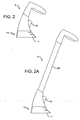
- the device 1 can be converted from a long stand-up or stick-like configuration (see FIG. 2A) to that of hand-held proportions (see FIG. 2).
- This conversion of the device 1 can be accomplished by many means, including folding about a rotatable joint 13 (see FIGS. 3 and 3A), removing an extension piece 15 (see FIGs. 2 and 2A), or collapsing a telescopic portion (not shown).
- a fluid container 6 for use with an electrohydrodynamic spray device 1 is provided.
- the device 1 can be reusable, recyclable or disposable, and is configured to engage the container 6 .
- the fluid container 6 comprises at least one reservoir configured for holding a sprayable liquid.
- the device 1 and/or container 6 are each configured so that when the container is engaged with the device 1 , at least a portion of the container 6 extends out from the device 1 for easy access by the user for replacing with a new or different container 6 , which container 6 can comprise a liquid formulation for spraying by the device 1 .
- the fluid container 6 can also be positioned within the handle of the device 1 . However, the user can still access the container 6 in this embodiment for changing thereof.
- the container 6 prevents any interaction between the user of the device 1 and the fluid that it sprays, thus contributing to user safety.
- the fluid container 6 further comprises at least one reservoir configured for holding a sprayable liquid, and at least one interface 23 in fluid communication with the reservoir.
- the fluid container 6 further comprises at least one manifold 22 comprising at least one fluid path 24 .
- the fluid path 24 is in fluid communication with the interface.
- the fluid container 6 can also contain a nozzle 8 comprising at least one spray site 25 that are in fluid communication with the fluid path 24 .
- the sprayable liquid can be selected from virtually any formulation one wishes to spray using electrohydrodynamic technology and, more particularly, can be selected from a rinsing or cleansing solution, a target preparation solution, a solution containing an active ingredient, a target sealing solution, or combinations thereof.
- the rinsing solution can be water or any other polar or non-polar solvent
- the target preparation solution can comprise a compound or series of compounds that, for example, open pores in the cuticle of a target (i.e., plant), such as, for example, an alkyl ester or fatty acid of other like oils (i.e., methyl oleate), which assist in the uptake and transport of certain systemic herbicidal compounds, such as, for example, a polar-acidic agrochemical complex like glyphosate, 2,4-D, glufosinate, or combinations thereof.
- a target i.e., plant
- an alkyl ester or fatty acid of other like oils i.e., methyl oleate
- certain systemic herbicidal compounds such as, for example, a polar-acidic agrochemical complex like glyphosate, 2,4-D, glufosinate, or combinations thereof.
- the active ingredient can be a pesticidal formulation and, more particularly, a pesticidal formulation selected from a herbicide, a fungicide, an insecticide, an acaricide, a miticide, a molluscicide, a nematicide, a rodenticide, a plant desiccant, a plant-growth regulator, or combinations thereof.
- the solution containing an active ingredient can be oil- or water-based, and can include the non-aqueous, oil-continuous microemulsions described in the PCT International Patent Application identified by Attorney Docket No. BAT 0080 PB/13894, the disclosure of which is incorporated herein by reference.
- the target sealing solution can comprise a compound or series of compounds that seal the pores of a target (i.e., plant) to seal in the active ingredient(s) and protect it from being compromised by natural or other environmental influences, such as, for example wind, (precipitation, such as rain, hail, ice) dust or irrigation.
- a target i.e., plant
- Such compound or series of compounds that seal the pores of the target can include film formers, preferably, low-cost film formers such as, for example, bone glue, polyvinyl alcohol, polyvinyl acetone, drying oils, and natural oils.
- the electrohydrodynamic spray device 1 and fluid container 6 can define a security feature relationship, such that the device 1 prevents the use of an unauthorized fluid container or cartridge 6 that contains a certain sprayable liquid formulation.
- the device 1 can be configured so that it only operates (sprays) when a container 6 containing a herbicidal formulation is engaged with the device 1 . Accordingly, in this configuration, if a user inserts a container 6 containing, for example, an insecticidal formulation, the device 1 will not operate. As a result, the user cannot accidentally or unintentionally apply the wrong formulation to a target.
- the device 1 can further comprise a container/contents recognition feedback loop 13 , which enables the passage of data via electrical signals from the container 6 to the control panel 2 .
- the control panel 2 functions both as a user interface and a controller that converts the user interface into appropriate electrical signals, which are in communication with the power source 3 , and pump control board 12 , etc.
- These electrical connections represent the input from the container 6 to the device 1 that the control panel 2 employs, alone or in combination with user input, to create electrical signals to the power source 3 , and/or pump control board 12 , which signals can vary depending upon the particular input from the container 6 .
- the fluid container 6 can also be configured so that certain formulations contained within the container 6 are recognized by the electrohydrodynamic spray device 1 causing settings such as voltage, flow rate, and spray application time, inter alia, to automatically adjust in accordance with preset specifications for certain liquid formulations.
- settings such as voltage, flow rate, and spray application time, inter alia, to automatically adjust in accordance with preset specifications for certain liquid formulations.
- This feature enables a user to operate the device 1 without having to change settings or time the application of a particular liquid formulation, thereby contributing to the ease of use of the present invention.
- the automatic adjustment of spray settings and delivery time further assists to ensure that a quality spray is produced, as well as delivery of a prescribed dose of a particular liquid formulation to a particular intended target.
- the fluid container or cartridge 6 can be configured so that the amount of liquid formulation contained within the container 6 can be measured by the electrohydrodynamic spray device 1 , which device 1 then alerts the user when the liquid formulation is near to being depleted and a new fluid container 6 is needed.
- the fluid container or cartridge 6 can be configured so that the expiration date of a certain liquid formulation contained within the container 6 can be determined by the spray device 1 , which device 1 then alerts the user when the particular formulation is expired and a new fluid container or cartridge 6 is needed.
- the container 6 can further comprise at least one fluid path 24 , at least one manifold 22 in fluid communication with the fluid path 24 , and at least one nozzle 8 .
- the nozzle 8 comprises a plurality of spray sites 25 that are in fluid communication with the manifold 22 .
- the fluid container 6 further comprises at least one reservoir configured for holding a sprayable liquid, and at least one interface 23 in fluid communication with the reservoir.
- the container 6 device 1 can comprise a single fluid path 24 , a manifold 22 in fluid communication with the fluid path 24 , and a common nozzle 8 .
- the nozzle 8 comprises at least one plurality of spray site 25 in fluid communication with the fluid path 24 .
- the container 6 comprises a reservoir configured for holding a sprayable liquid, as defined herein, and an interface 23 which is in fluid communication with the reservoir and the fluid path 14.
- individual containers 6 are employed for each specific type of application, such as, for example, individual formulation containers 6 that each separately contain herbicidal, insecticidal or fungicidal compounds, inter alia.
- the fluid container 6 can optionally define a separate container containing a rinsing or cleansing solution, which solution can be sprayed or pumped through the nozzle 8 before and after each use of a formulation container 6 containing an active ingredient.
- the nozzle 8 and fluid container 6 can optionally define a single unit, which would eliminate the need to clean or flush the nozzle 8 after using a formulation container 6 .
- a series of individual fluid containers 6 can be employed to, for example, a) pre-rinse the nozzle 8 (if not coupled with the fluid container 6 ), prepare the target (e.g., apply a formulation which opens the pores of a plant), c) apply the active ingredient (e.g., a pesticidal formulation), d) seal the target (e.g., apply a pore sealer to the targeted plant to seal in the pesticidal formulation and protect it from being compromised by environmental influences), and e) post-rinse the nozzle 8 .
- the target e.g., apply a formulation which opens the pores of a plant
- the active ingredient e.g., a pesticidal formulation
- seal the target e.g., apply a pore sealer to the targeted plant to seal in the pesticidal formulation and
- the container 6 can comprise two or more separate fluid paths 24 , two or more separate manifolds 22 , each in fluid communication with one of the separate fluid paths 22 , and a common nozzle 8 .
- the common nozzle 8 can comprise a plurality of spray sites 25, each in fluid communication with one of the separate manifolds 22 . It is to be understood, however, that each separate manifold 22 is in fluid communication with a plurality of spray sites 25 .
- the container 6 can comprise two or more separate reservoirs, each configured for holding its own disparate sprayable liquid.
- the container 6 can also comprise two or more interfaces 23 , each one in fluid communication with one of the reservoirs as well as one of the fluid paths 24 .
- each container 6 can contain one or more of the following, as defined herein, in each of the two or more separate reservoirs: a) a cleaning or rinsing solution, b) a target preparation solution, c) a solution containing an active ingredient (e.g., a pesticidal formulation), and d) a target sealing solution.
- a cleaning or rinsing solution e.g., a cleaning or rinsing solution
- a target preparation solution e.g., a pesticidal formulation
- a solution containing an active ingredient e.g., a pesticidal formulation
- a target sealing solution e.g., a target sealing solution.
- a fluid containment system comprising two or more fluid containers 6 , each comprising at least one fluid path 24 and at least one manifold 22 , each in fluid communication with one of the fluid paths 24 , and a common nozzle 8 .
- the common nozzle 8 comprises at least one spray site 25 , each in fluid communication with one of the manifolds 22 .
- each manifold 22 is in fluid communication with at least one spray site 25 .
- each container 6 will typically comprise a single reservoir configured for holding a sprayable liquid, as well as an interface 23 in fluid communication with the reservoir and one of the fluid paths 25 .
- each container 6 can comprise two or more separate reservoirs, each reservoir configured for holding disparate sprayable liquids, and each reservoir being in fluid communication with one of the fluid paths 24 .
- the device 1 is configured to be engaged with multiple containers 6 and thus apply a plurality of disparate sprayable liquids through a common nozzle 8 .
- the user would indicate to the device 1 which container 6 to use for a given application by operating the control panel 2 (i.e., the cleaning solution container, the target preparation solution container, the active ingredient container; or the target sealing solution container, inter alia ). Accordingly, multistage application of different formulations is provided without having to change containers 6 .
- This feature could provide a cost advantage to the preparation of individual fluid containers 6 that comprise multiple liquid formulations, (e.g., containers comprising more than one reservoir, each configured for holding disparate sprayable liquids).
- the common nozzle 8 can be automatically cleaned by employing a cleaning solution container prior to and following each application of a liquid formulation containing an active ingredient.
- the container 6 can comprise two or more separate fluid paths 24 , two or more separate manifolds 22 , each manifold 22 in fluid communication with one of the fluid paths 24 , and two or more nozzles 8 , each comprising at least one spray sites 25 in fluid communication with one of the manifolds 22 .
- each manifold 22 is in fluid communication with at least one spray site 25 .
- the container 6 can comprise two or more reservoirs, each reservoir configured for holding disparate sprayable liquid, and two or more interfaces 23 , each interface 23 in fluid communication with one of the reservoirs and one of the fluid paths 24 .
- each nozzle 8 in fluid communication with one of the manifolds 22 and, therefore, a disparate sprayable liquid, can successfully encapsulate formulations during the aerosolization thereof by the device 1 in order to increase biological efficacy. Accordingly, this particular feature could allow, for example, the combining of glyphosate with other fast acting herbicidal active ingredients for quick kill visualization of undesirable vegetation.
- the two or more nozzles 8 each one in fluid communication with a disparate liquid formulation, can be sprayed simultaneously to provide a broader spectrum of active ingredients to a target. This allows for greater flexibility in the design of formulations by mixing during the aerosolization process, such as, for example, the mixing of volatile formulations.
- a method of delivering a sprayable liquid to a target by means of electrohydrodynamics comprising: a) loading a fluid container into an electrohydrodynamic spray device, wherein the fluid container holds a sprayable liquid; b) entering data on the sprayable liquid into the device; c) priming the device such that the sprayable liquid is delivered to a nozzle in fluid communication with the container; d) positioning the nozzle adjacent to the target; and e) delivering the sprayable liquid to the target as a charged aerosol by activating the electrohydrodynamic spray device.
- the fluid container can be configured so that entering data on the sprayable liquid is automatic upon loading of the fluid container into the electrohydrodynamic device.
- priming of the device can be automatically performed upon loading of the fluid container into the device, or upon activating the device. This step can be performed by activating a pumping mechanism in the device, which pump delivers the sprayable liquid into and through a manifold to each of a plurality of spray sites in a nozzle. Accordingly, after priming is complete, there is sprayable liquid at each spray site.
- the container can be configured so that upon insertion of the container into the cartridge housing, the container notifies the device of its contents, and the device processes the appropriate parameters for spraying the contents of that particular container. Accordingly, the device can be backward compatible for containers, even if the device is made to adjust for parameters not originally programmed. Software upgrades for the device can allow for more contents (or defined parameters) over time.
- the container can be configured so that upon insertion of the container into the device, the container notifies the device of the particular parameters needed for spraying. This information can be passed by electronic, mechanical and magnetic means. As such, the containers can be backward compatible with the device.
- activating the device After positioning the nozzle adjacent to the target, activating the device will deliver a dose of sprayable liquid to the target in accordance with the flow rate, activation time and voltage which is pre-set for the particular liquid being sprayed.
- Multiple targets can be sprayed by repeating the method steps.
- the fluid container can remain in the device or it can be removed. Accordingly, upon powering off the device, the sprayable liquid can be automatically drawn back into the container.
- Cleaning or rinsing the device (i.e., nozzle) of the sprayable liquid can be performed by a purge step, wherein a rinsing formulation (i.e., water) is pumped through the nozzle.
- the rinsing formulation can be contained in a separate fluid container, or in the same container that contains an active, that container comprising multiple reservoirs in accordance with the present invention.
- the following table sets out some of the spraying variables which can be pre-set in the device depending upon the specific sprayable liquid formulations contained within the fluid container, the dose desired (and thus concentration of active), and manifold size.
Landscapes
- Life Sciences & Earth Sciences (AREA)
- Engineering & Computer Science (AREA)
- Insects & Arthropods (AREA)
- Pest Control & Pesticides (AREA)
- Wood Science & Technology (AREA)
- Zoology (AREA)
- Environmental Sciences (AREA)
- Containers And Packaging Bodies Having A Special Means To Remove Contents (AREA)
- Catching Or Destruction (AREA)
- Nozzles (AREA)
- Application Of Or Painting With Fluid Materials (AREA)
Abstract
Description
- The present invention relates to a portable electrohydrodynamic spray device and a device for the application of the electrically charged particles of material so produced. More particularly, the invention relates to a portable electrohydrodynamic spray device and method of using same for the application of chemical agents such as, for example, herbicides, fungicides, insecticides, acaricides, miticides, molluscicides, nematicides, rodenticides, plant desiccants, plant-growth regulators, etc. (pesticides in general), to a target.
- The application of liquid formulations to crops, turfs, trees, and other plants as well as spraying of pesticides in and around the home using sprayers has been practiced for many years. More specifically, electrostatic sprayers have been developed to atomize pesticides for application on a target. For example, Coffee, U. S. Patent No. 4,356, 528, teaches an electrostatic sprayer to be used for ultra-low volume ("ULV") spraying of pesticides. The sprayer includes multiple metal capillary tubes as spray nozzles, an insulating cover, and a field-intensifying ring electrode. Other examples of electrostatic sprayers include U. S. Patent Nos. 4,376, 514; 4,467, 961; 4,470, 550; 4,735, 364; 4,476, 515; 4,580, 721; 4,629, 164; and 6,105, 571. However, no electrostatic sprayer system is known which allows for variations in spraying parameters in response to formulations/active ingredients sprayed through one or more nozzles. Prior to the present invention, electrostatic devices and fluid containers were instead tailored to the specific formulations or active ingredient being delivered. Accordingly, there is a recognized need for improvements in electrohydrodynamic sprayer design.
- WO02/055211 describes an electrostatic spray device with a disposable product cartridge having a single outlet nozzle for spraying liquids such as cosmetics, skin preparations and lotions. In order to address the problem of high voltage induced emulsion product separation, WO02/055211 provides a conductive high voltage shield to reduce electrically induced emulsion product separation or configures the device or cartridge to prevent product at the charging site from being in fluid communication with the product reservoir.
- In a first aspect, the present invention provides a portable electrohydrodynamic spray device as set out in
claim 1. - In a second aspect, the present invention provides a method of spraying a target as set out in claim 20.
- The present invention also provides a replaceable container or cartridge for attachment to an electrohydrodynamic spray device of the first aspect.
- As used herein, the terms fluid "container" and "cartridge"are intended to be interchangeable, and each can be defined as a vessel for holding a liquid formulation that is sprayed by the electrohydrodynamic device. Although the present invention is not limited to specific advantages or functionality, it is noted that the fluid cartridge contributes to user safety by defining a secured cartridge that prevents any interaction between the user of the electrohydrodynamic sprayer and the liquid formulation that is being sprayed. The design of the fluid cartridge provides for quick and easy operator("do-it-yourselfer") change over of formulations and active ingredients. Also, the fluid cartridge is configured for ease of clean up in all steps of operation and is relatively small in size, which minimizes waste.
- Moreover, the fluid cartridge can be configured to be refillable, recyclable, or disposable following its use.
- It is contemplated that the present invention has applications both inside and outside of homes as well as businesses or industrial environments. In addition, the scale of use of the present invention can reach from individual pest treatments (e. g., weeds), to targeted or specific areas of treatment, through commercial large-scale use. Various formulations and active ingredient fluids have different electrohydrodynamic spraying requirements (e. g., flow rate, voltage, etc.), which can be accommodated by the present invention either manually or automatically via a cartridge/contents recognition feedback loop and control panel. Accordingly, the fluid cartridge can be configured so that the electrohydrodynamic spray device automatically adjusts certain settings in response to particular formulations within the fluid cartridge. This feature contributes to the ease of use of the present invention and assures the delivery of a quality spray, as well as a prescribed dose of a liquid formulation to an intended target. Moreover, the fluid cartridge can incorporate security features such that the electrohydrodynamic spray device prevents the spraying of an unauthorized fluid formulation.
- The fluid cartridge can be configured so that the amount and expiration date of the liquid formulation within the cartridge is recognized by the electrohydrodynamic device, which alerts the user when a new fluid cartridge is needed. Accordingly, long-term storage of liquid formulations within the fluid cartridge of the present invention are possible with no degradation of system operation and efficiency parameters. Moreover, the fluid cartridge can be configured to automatically rinse the electrohydrodynamic nozzle and/or the cartridge itself of a liquid formulation via a cleansing and/or pumping mechanism, which can be part of the cartridge, the delivery device, or a separate element.
- The fluid cartridge can be provided with various nozzle/ fluid/ cartridge configurations, with a variety of formulations or active ingredients, used in series with a common nozzle or set of multiple nozzles. As described with more particularity herein, the device is configured for easy insertion and removal of cartridges housing different formulations or active ingredients (in a variety of forms), each cartridge having one or more formulation or active ingredient. Moreover, means to ensure that the electrohydrodynamic spray device is not plugged or fouled by cross-contamination or aged material can be provided in a variety of ways (e. g., flush, purge, fluid, air, separate fluid paths, etc.), if necessary.
- The fluid cartridge may comprise two or more separate reservoirs, each configured for holding a disparate sprayable liquid.
- In an embodiment, a fluid containment system comprises two or more such fluid cartridges. Optionally, at least one fluid cartridge comprises two or more reservoirs for holding disparate sprayable liquids, the interface means provides a respective interface for each reservoir and the manifold provides a respective flow path for each reservoir.
- The present invention also provides a fluid containment system comprising a portable electrohydrodynamic spray device in accordance with the first aspect and one or more further such replaceable containers or cartridges.
- These and other features and advantages of the invention will be more fully understood from the following detailed description of the invention taken together with the accompanying drawings.
- The following detailed description of the embodiments of the present invention can be best understood when read in conjunction with the following drawings, where like structure is indicated with like reference numerals and in which:
- FIG.1 is a schematic block diagram showing some of the different components that make up an electrohydrodynamic spray device comprising a fluid cartridge in accordance with one embodiment of the present invention;
- FIGS. 2 and 2A show schematic side views of an electrohydrodynamic spray device that includes a fluid container in accordance with another embodiment of the present invention;
- FiGs. 3 and 3A show schematic side views of an electrohydrodynamic spray device including a fluid container in accordance with still another embodiment of the present invention;
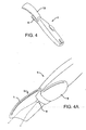
- FIGs. 4 and 4A show schematic perspective views of an electrohydrodynamic spray device that includes a fluid container in accordance with yet another embodiment of the present invention;
- FIGs. 5 and 5A show a schematic perspective and side view, respectively, of an electrohydrodynamic spray device that includes a fluid container in accordance with yet still another embodiment of the present invention;
- FIG. 6 shows a schematic perspective view of an electrohydrodynamic spray device that includes a fluid container in accordance with yet still another embodiment of the present invention;
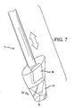
- FIG. 7 shows a schematic perspective view of an electrohydrodynamic spray device that includes a fluid container in accordance with yet still another embodiment of the present invention;
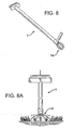
- FIGs. 8 and 8A show a schematic perspective and side view, respectively, of an electrohydrodynamic spray device that includes a fluid container in accordance with yet still another embodiment of the present invention;
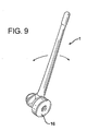
- FIG. 9 shows a schematic perspective view of an electrohydrodynamic spray device that includes a fluid container in accordance with yet still another embodiment of the present invention;
- FIG. 10 shows a schematic side view of an electrohydrodynamic spray device that includes a fluid container in accordance with yet still another embodiment of the present invention; and
- FIG. 11 shows a schematic illustration of a manifold for an electrohydrodynamic spray device in accordance with the present invention.
- Skilled artisans appreciate that elements in the figures are illustrated for simplicity and clarity and have not necessarily been drawn to scale. For example, the dimensions of some of the elements in the figures may be exaggerated relative to other elements to help improve understanding of embodiment(s) of the present invention.
- Referring initially to FIG. 1, a schematic block diagram of an
electrohydrodynamic spray device 1 is illustrated. Thedevice 1 can comprise the following components: acontrol panel 2, apower source 3, a pumping mechanism 4, a fluid container/cartridge 6, anozzle 8, and aspray head 10. Reference is made to the following commonly assigned PCT International Patent Application entitled "SPRAY HEAD FOR ELECTROHYDRODYNAMIC SPRAY DEVICE AND ELECTROHYDRODYNAMIC SPRAYER SYSTEM" (Attorney Docket No. BAT 0079 PB / 40078.256), the disclosure of which further describes the components that make up thedevice 1 and is incorporated herein by reference. The components can be connected by a plurality of electrical and mechanical interfaces. Thedevice 1 can be configured to be portable and effectively provides a charged aerosol of a liquid formulation by means of electrohydrodynamics. - The
control panel 2 provides an interface between thedevice 1 and the operator of thedevice 1 and can comprise one or more electrical switches for thepower supply 3 and pump b, as well as several warning LEDs for low battery and high voltage power, inter alia. Thepower source 3 can comprise one or more batteries, and can be configured to convert low DC voltage to the high DC voltage needed for aerosolization. By "high" DC voltage, we mean voltage in the kilovolt range. The fluid container/cartridge 6 is in fluid communication with the pumping mechanism 4 and thenozzle 8. Alternatively, thefluid container 6, pumping mechanism 4, pump control board 12,nozzle 8, or combinations thereof, can be assembled or included as a unit as part of thespray head 10. In any event, the pumping mechanism 4 is configured to pump a volume of liquid formulation from the fluid container/cartridge 6 to thenozzle 8 at a controlled flow rate, and can comprise a motion control circuit board and a DC motor (not shown), inter alia. The flow rate of the pumping mechanism 4 can be controlled by a pump control board 12. The liquid formulation can contain an active ingredient, such as a pesticidal compound. - The high voltage provided by the
power source 3, pumping flow rate by way of the pump control board 12, and application time are all easily adjustable on thedevice 1. Thedevice 1 in response to certain preset specifications for spraying a particular liquid formulation can make adjustments automatically. This feature contributes to the ease of use of thedevice 1. The user of thedevice 1 can also make adjustments manually. Accordingly, due to its versatility and ability to spray a wide variety of formulations, asingle device 1 can be used for a wealth of different applications. For example, thedevice 1 can be employed for applying a pesticide to a particular target plant or animal. Since the flow rate of the formulation is controlled during a particular application, the dosage applied to the plant or animal is also very controllable, which provides for efficiency in application. Moreover, in order to configure thedevice 1 so that it is comfortable to use for a variety of people, as well as configured to spray a variety of sizes of plants, the size of thedevice 1 can also be adjustable. For example, thedevice 1 can be converted from a long stand-up or stick-like configuration (see FIG. 2A) to that of hand-held proportions (see FIG. 2). This conversion of thedevice 1 can be accomplished by many means, including folding about a rotatable joint 13 (see FIGS. 3 and 3A), removing an extension piece 15 (see FIGs. 2 and 2A), or collapsing a telescopic portion (not shown). - In accordance with one exemplary embodiment of the present invention, a
fluid container 6 for use with anelectrohydrodynamic spray device 1 is provided. Thedevice 1 can be reusable, recyclable or disposable, and is configured to engage thecontainer 6. Thefluid container 6 comprises at least one reservoir configured for holding a sprayable liquid. As illustrated in FIGS. 2, 2A, 3, 3A, 4, 4A, 6, 7, 8, 8A, 9 and 10, thedevice 1 and/orcontainer 6, are each configured so that when the container is engaged with thedevice 1, at least a portion of thecontainer 6 extends out from thedevice 1 for easy access by the user for replacing with a new ordifferent container 6, whichcontainer 6 can comprise a liquid formulation for spraying by thedevice 1. The arrows in FIG. 7 illustrate the changing of thefluid container 6. In accordance with the present invention, as illustrated in FIGs. 5 and 5A, thefluid container 6 can also be positioned within the handle of thedevice 1. However, the user can still access thecontainer 6 in this embodiment for changing thereof. Thecontainer 6 prevents any interaction between the user of thedevice 1 and the fluid that it sprays, thus contributing to user safety. - The
fluid container 6, further comprises at least one reservoir configured for holding a sprayable liquid, and at least oneinterface 23 in fluid communication with the reservoir. Thefluid container 6 further comprises at least onemanifold 22 comprising at least onefluid path 24. Thefluid path 24 is in fluid communication with the interface. Thefluid container 6 can also contain anozzle 8 comprising at least onespray site 25 that are in fluid communication with thefluid path 24. The sprayable liquid can be selected from virtually any formulation one wishes to spray using electrohydrodynamic technology and, more particularly, can be selected from a rinsing or cleansing solution, a target preparation solution, a solution containing an active ingredient, a target sealing solution, or combinations thereof. The rinsing solution can be water or any other polar or non-polar solvent, and the target preparation solution can comprise a compound or series of compounds that, for example, open pores in the cuticle of a target (i.e., plant), such as, for example, an alkyl ester or fatty acid of other like oils (i.e., methyl oleate), which assist in the uptake and transport of certain systemic herbicidal compounds, such as, for example, a polar-acidic agrochemical complex like glyphosate, 2,4-D, glufosinate, or combinations thereof. As such, the active ingredient can be a pesticidal formulation and, more particularly, a pesticidal formulation selected from a herbicide, a fungicide, an insecticide, an acaricide, a miticide, a molluscicide, a nematicide, a rodenticide, a plant desiccant, a plant-growth regulator, or combinations thereof. The solution containing an active ingredient can be oil- or water-based, and can include the non-aqueous, oil-continuous microemulsions described in the PCT International Patent Application identified by Attorney Docket No. BAT 0080 PB/13894, the disclosure of which is incorporated herein by reference. The target sealing solution can comprise a compound or series of compounds that seal the pores of a target (i.e., plant) to seal in the active ingredient(s) and protect it from being compromised by natural or other environmental influences, such as, for example wind, (precipitation, such as rain, hail, ice) dust or irrigation. Such compound or series of compounds that seal the pores of the target can include film formers, preferably, low-cost film formers such as, for example, bone glue, polyvinyl alcohol, polyvinyl acetone, drying oils, and natural oils. - The
electrohydrodynamic spray device 1 andfluid container 6 can define a security feature relationship, such that thedevice 1 prevents the use of an unauthorized fluid container orcartridge 6 that contains a certain sprayable liquid formulation. For example, thedevice 1 can be configured so that it only operates (sprays) when acontainer 6 containing a herbicidal formulation is engaged with thedevice 1. Accordingly, in this configuration, if a user inserts acontainer 6 containing, for example, an insecticidal formulation, thedevice 1 will not operate. As a result, the user cannot accidentally or unintentionally apply the wrong formulation to a target. - As illustrated in FIG. 1, the
device 1 can further comprise a container/contentsrecognition feedback loop 13, which enables the passage of data via electrical signals from thecontainer 6 to thecontrol panel 2. It is contemplated that thecontrol panel 2 functions both as a user interface and a controller that converts the user interface into appropriate electrical signals, which are in communication with thepower source 3, and pump control board 12, etc. These electrical connections represent the input from thecontainer 6 to thedevice 1 that thecontrol panel 2 employs, alone or in combination with user input, to create electrical signals to thepower source 3, and/or pump control board 12, which signals can vary depending upon the particular input from thecontainer 6. As such, thefluid container 6 can also be configured so that certain formulations contained within thecontainer 6 are recognized by theelectrohydrodynamic spray device 1 causing settings such as voltage, flow rate, and spray application time, inter alia, to automatically adjust in accordance with preset specifications for certain liquid formulations. This feature enables a user to operate thedevice 1 without having to change settings or time the application of a particular liquid formulation, thereby contributing to the ease of use of the present invention. The automatic adjustment of spray settings and delivery time further assists to ensure that a quality spray is produced, as well as delivery of a prescribed dose of a particular liquid formulation to a particular intended target. - In addition, the fluid container or
cartridge 6 can be configured so that the amount of liquid formulation contained within thecontainer 6 can be measured by theelectrohydrodynamic spray device 1, whichdevice 1 then alerts the user when the liquid formulation is near to being depleted and a newfluid container 6 is needed. Moreover, the fluid container orcartridge 6 can be configured so that the expiration date of a certain liquid formulation contained within thecontainer 6 can be determined by thespray device 1, whichdevice 1 then alerts the user when the particular formulation is expired and a new fluid container orcartridge 6 is needed. - As shown in FIG. 11, the
container 6 can further comprise at least onefluid path 24, at least onemanifold 22 in fluid communication with thefluid path 24, and at least onenozzle 8. Thenozzle 8 comprises a plurality ofspray sites 25 that are in fluid communication with the manifold 22. Thefluid container 6 further comprises at least one reservoir configured for holding a sprayable liquid, and at least oneinterface 23 in fluid communication with the reservoir. - In accordance with another embodiment of the present invention, the
container 6device 1 can comprise asingle fluid path 24, a manifold 22 in fluid communication with thefluid path 24, and acommon nozzle 8. Thenozzle 8 comprises at least one plurality ofspray site 25 in fluid communication with thefluid path 24. Thecontainer 6 comprises a reservoir configured for holding a sprayable liquid, as defined herein, and aninterface 23 which is in fluid communication with the reservoir and thefluid path 14. In this configuration,individual containers 6 are employed for each specific type of application, such as, for example,individual formulation containers 6 that each separately contain herbicidal, insecticidal or fungicidal compounds, inter alia. Moreover, thefluid container 6 can optionally define a separate container containing a rinsing or cleansing solution, which solution can be sprayed or pumped through thenozzle 8 before and after each use of aformulation container 6 containing an active ingredient. - The
nozzle 8 andfluid container 6 can optionally define a single unit, which would eliminate the need to clean or flush thenozzle 8 after using aformulation container 6. Moreover, a series ofindividual fluid containers 6 can be employed to, for example, a) pre-rinse the nozzle 8 (if not coupled with the fluid container 6), prepare the target (e.g., apply a formulation which opens the pores of a plant), c) apply the active ingredient (e.g., a pesticidal formulation), d) seal the target (e.g., apply a pore sealer to the targeted plant to seal in the pesticidal formulation and protect it from being compromised by environmental influences), and e) post-rinse thenozzle 8. - In accordance with yet another embodiment of the present invention, the
container 6 can comprise two or moreseparate fluid paths 24, two or moreseparate manifolds 22, each in fluid communication with one of theseparate fluid paths 22, and acommon nozzle 8. Thecommon nozzle 8 can comprise a plurality ofspray sites 25, each in fluid communication with one of theseparate manifolds 22. It is to be understood, however, that eachseparate manifold 22 is in fluid communication with a plurality ofspray sites 25. Thecontainer 6 can comprise two or more separate reservoirs, each configured for holding its own disparate sprayable liquid. Thecontainer 6 can also comprise two ormore interfaces 23, each one in fluid communication with one of the reservoirs as well as one of thefluid paths 24. In this configuration, eachcontainer 6 can contain one or more of the following, as defined herein, in each of the two or more separate reservoirs: a) a cleaning or rinsing solution, b) a target preparation solution, c) a solution containing an active ingredient (e.g., a pesticidal formulation), and d) a target sealing solution. Where thefluid container 6 of the instant embodiment houses multiple disparate sprayable liquids in separate reservoirs, only one container needs to be employed for multiple applications and multistage application is automatic (the user does not need to change containers between treating a target and flushing the common nozzle 8). Accordingly, thenozzle 8 can be automatically cleaned before and after each use and container formulations (e.g., pesticides) can be rinsed from thecontainer 6 at the end of the useful lifetime of thecontainer 6 for easy disposal thereof. - In accordance with still another embodiment of the present invention, a fluid containment system is provided comprising two or more
fluid containers 6, each comprising at least onefluid path 24 and at least onemanifold 22, each in fluid communication with one of thefluid paths 24, and acommon nozzle 8. Thecommon nozzle 8 comprises at least onespray site 25, each in fluid communication with one of the manifolds 22. Again, it is to be understood that each manifold 22 is in fluid communication with at least onespray site 25. While two ormore containers 6 can be engaged with thedevice 1. In accordance with this embodiment of the present invention, eachcontainer 6 will typically comprise a single reservoir configured for holding a sprayable liquid, as well as aninterface 23 in fluid communication with the reservoir and one of thefluid paths 25. However, it is also contemplated that eachcontainer 6 can comprise two or more separate reservoirs, each reservoir configured for holding disparate sprayable liquids, and each reservoir being in fluid communication with one of thefluid paths 24. Accordingly, thedevice 1 is configured to be engaged withmultiple containers 6 and thus apply a plurality of disparate sprayable liquids through acommon nozzle 8. In use, the user would indicate to thedevice 1 whichcontainer 6 to use for a given application by operating the control panel 2 (i.e., the cleaning solution container, the target preparation solution container, the active ingredient container; or the target sealing solution container, inter alia). Accordingly, multistage application of different formulations is provided without having to changecontainers 6. This feature could provide a cost advantage to the preparation ofindividual fluid containers 6 that comprise multiple liquid formulations, (e.g., containers comprising more than one reservoir, each configured for holding disparate sprayable liquids). Moreover, in accordance with the present embodiment, thecommon nozzle 8 can be automatically cleaned by employing a cleaning solution container prior to and following each application of a liquid formulation containing an active ingredient. - In accordance with yet still another embodiment of the present invention, the
container 6 can comprise two or moreseparate fluid paths 24, two or moreseparate manifolds 22, each manifold 22 in fluid communication with one of thefluid paths 24, and two ormore nozzles 8, each comprising at least onespray sites 25 in fluid communication with one of the manifolds 22. Here too, it is to be understood that each manifold 22 is in fluid communication with at least onespray site 25. Optionally, thecontainer 6 can comprise two or more reservoirs, each reservoir configured for holding disparate sprayable liquid, and two ormore interfaces 23, eachinterface 23 in fluid communication with one of the reservoirs and one of thefluid paths 24. - In addition to the features and advantages of the different embodiments of the present invention that are described herein, the instant embodiment by employing
dual nozzles 8, eachnozzle 8 in fluid communication with one of themanifolds 22 and, therefore, a disparate sprayable liquid, can successfully encapsulate formulations during the aerosolization thereof by thedevice 1 in order to increase biological efficacy. Accordingly, this particular feature could allow, for example, the combining of glyphosate with other fast acting herbicidal active ingredients for quick kill visualization of undesirable vegetation. Moreover, the two ormore nozzles 8, each one in fluid communication with a disparate liquid formulation, can be sprayed simultaneously to provide a broader spectrum of active ingredients to a target. This allows for greater flexibility in the design of formulations by mixing during the aerosolization process, such as, for example, the mixing of volatile formulations. - In accordance with yet still another embodiment of the present invention, a method of delivering a sprayable liquid to a target by means of electrohydrodynamics is provided comprising: a) loading a fluid container into an electrohydrodynamic spray device, wherein the fluid container holds a sprayable liquid; b) entering data on the sprayable liquid into the device; c) priming the device such that the sprayable liquid is delivered to a nozzle in fluid communication with the container; d) positioning the nozzle adjacent to the target; and e) delivering the sprayable liquid to the target as a charged aerosol by activating the electrohydrodynamic spray device. As noted herein, the fluid container can be configured so that entering data on the sprayable liquid is automatic upon loading of the fluid container into the electrohydrodynamic device. Also, priming of the device can be automatically performed upon loading of the fluid container into the device, or upon activating the device. This step can be performed by activating a pumping mechanism in the device, which pump delivers the sprayable liquid into and through a manifold to each of a plurality of spray sites in a nozzle. Accordingly, after priming is complete, there is sprayable liquid at each spray site.
- In accordance with the present invention, the container can be configured so that upon insertion of the container into the cartridge housing, the container notifies the device of its contents, and the device processes the appropriate parameters for spraying the contents of that particular container. Accordingly, the device can be backward compatible for containers, even if the device is made to adjust for parameters not originally programmed. Software upgrades for the device can allow for more contents (or defined parameters) over time. In contrast, the container can be configured so that upon insertion of the container into the device, the container notifies the device of the particular parameters needed for spraying. This information can be passed by electronic, mechanical and magnetic means. As such, the containers can be backward compatible with the device.
- After positioning the nozzle adjacent to the target, activating the device will deliver a dose of sprayable liquid to the target in accordance with the flow rate, activation time and voltage which is pre-set for the particular liquid being sprayed. Multiple targets can be sprayed by repeating the method steps. When spraying is complete, the fluid container can remain in the device or it can be removed. Accordingly, upon powering off the device, the sprayable liquid can be automatically drawn back into the container. Cleaning or rinsing the device (i.e., nozzle) of the sprayable liquid can be performed by a purge step, wherein a rinsing formulation (i.e., water) is pumped through the nozzle. The rinsing formulation can be contained in a separate fluid container, or in the same container that contains an active, that container comprising multiple reservoirs in accordance with the present invention.
- The following table sets out some of the spraying variables which can be pre-set in the device depending upon the specific sprayable liquid formulations contained within the fluid container, the dose desired (and thus concentration of active), and manifold size.

- While the invention has been described by reference to certain preferred embodiments, it should be understood that numerous changes could be made within the spirit and scope of the inventive concepts described. This includes modification to the embodiment shown in sketches from hand-held devices to other configurations which include but are not limited to boomed devices pulled behind tractors, stationary-frames used to place a plant in to treat, and devices integrally installed in green-houses/glass-houses devices. Accordingly, it is intended that the invention not be limited to the disclosed embodiments, but that it have the full scope permitted by the language of the following claims.
Claims (28)
- A portable electrohydrodynamic spray device configured to be held by an operator, the device having:a spray head (10) comprising a replaceable cartridge comprising sprayable liquid reservoir means (6) and outlet nozzle means (8, 25); anda power source (3) for providing a voltage to subject liquid issuing from the outlet nozzle means (8) to an electric field to cause electrohydrodynamic processing of the liquid to produce a spray,characterised in that the replaceable cartridge has a manifold (22) in fluid communication with said liquid reservoir means (6) via interface means (23) and in fluid communication with the outlet nozzle means (8,25) to provide a plurality of flow paths (24) between the liquid reservoir means (6) and the outlet nozzle means (8,25), and
the device has control means (2, 12) for enabling determination of spraying parameters in accordance with the liquid to be sprayed from the replaceable cartridge received by the device. - A portable electrohydrodynamic spray device according to claim 1, wherein a body of said electrohydrodynamic spray device and said replaceable cartridge are each configured so that, when said replaceable cartridge is engaged with said body of said electrohydrodynamic spray device, at least a portion of said replaceable cartridge extends out from said body of said electrohydrodynamic spray device.
- A portable electrohydrodynamic spray device according to claim 1 or 2, wherein said replaceable cartridge is configured to prevent any interaction between a user of said electrohydrodynamic spray device and said sprayable liquid contained within said replaceable cartridge.
- A portable electrohydrodynamic spray device according to claim 1, 2 or 3, wherein said replaceable cartridge is configured to cause, when said replaceable cartridge is engaged with said electrohydrodynamic spray device, said control means (2, 12) of said electrohydrodynamic spray device to at least one of:recognize said replaceable cartridge and automatically adjust certain pre-defined settings in accordance with the characteristics of said sprayable liquid; recognize said liquid replaceable cartridge and allow spraying; and recognize the amount and/or expiration date of said sprayable liquid contained within said replaceable cartridge and alert a user of said electrohydrodynamic spray device when a new replaceable cartridge is required.
- A portable electrohydrodynamic spray device according to claim 1, 2 or 3, wherein said replaceable cartridge is configured to cause, when said replaceable cartridge is engaged with said electrohydrodynamic spray device, said control means (2, 12) of said electrohydrodynamic spray device to recognize said replaceable cartridge and automatically adjust certain pre-defined settings entered manually by a user using a control panel (2) of said electrohydrodynamic spray device in accordance with the characteristics of said sprayable liquid.
- A portable electrohydrodynamic spray device according to any preceding claim, wherein the liquid reservoir means comprises two or more separate sprayable liquid reservoirs each coupled to the outlet nozzle means (8, 25) via a corresponding interface of the interface means (23) and a respective separate fluid path of the manifold (22).
- A portable electrohydrodynamic spray device according to any preceding claim, wherein the liquid reservoir means (6) comprises two or more separate sprayable liquid reservoirs each coupled via a corresponding interface of the interface means (23) to the same fluid path of the manifold (22).
- A portable electrohydrodynamic spray device according to claim 6 or 7, wherein the different reservoirs contain liquids comprising different ones or different combinations of a rinsing agent, a target preparation agent, a target sealing agent and an active ingredient.
- A portable electrohydrodynamic spray device according to any of claims 1 to 5, wherein said the liquid reservoir means (6) contains at least an active ingredient sprayable liquid.
- A portable electrohydrodynamic spray device according to any of claims 1 to 5, wherein said the liquid reservoir means (6) is configured to hold a first sprayable liquid comprising an active ingredient and a second sprayable liquid comprising one or more of a rinsing agent, a target preparation agent, a target sealing agent.
- A portable electrohydrodynamic spray device according to any preceding claim, wherein the liquid reservoir means (6) contains sprayable liquid comprising: a water-based solution containing an active ingredient; an oil-based solution containing an active ingredient; or an oil-based non- aqueous, oil-continuous microemulsion.
- A portable electrohydrodynamic spray device according to any of claims 1 to 10, wherein the liquid reservoir means (6) contains sprayable liquid comprising: a pesticidal formulation, for example a pesticidal formulation selected from: a herbicide, for example a polar-acidic agrochemical complex selected from glyphosate, 2,4-D, glufosinate, or combinations thereof; a fungicide; an insecticide; an acaricide; a miticide; a molluscicide; a nematicide; a rodenticide; a plant desiccant; a plant-growth regulator; or combinations thereof.
- A portable electrohydrodynamic spray device according to any preceding claim, wherein the liquid reservoir means (6) contains sprayable liquid comprising a rinsing liquid comprising: a polar solvent; a non-polar solvent; or water.
- A portable electrohydrodynamic spray device according to any preceding claim, wherein the liquid reservoir means (6) contains sprayable liquid comprising a target preparation liquid comprising an ingredient that opens pores in the cuticle of a target, for example an alkyl ester of a fatty acid, such as methyl oleate.
- A portable electrohydrodynamic spray device according to any preceding claim, wherein the liquid reservoir means (6) contains sprayable liquid comprising a target sealing agent that seals pores in a cuticle of a target, for example a target sealing agent selected from bone glue, polyvinyl alcohol, polyvinyl acetate, drying oils, natural oils, and combinations thereof.
- A portable electrohydrodynamic spray device according to any preceding claim, wherein the outlet nozzle means (8,25) has a plurality of outlet nozzles each coupled to a respective fluid path of the manifold (22).
- A portable electrohydrodynamic spray device according to claim 16, wherein the manifold (22) has a passageway providing a succession of liquid flow path stages (24) which together define the liquid flow paths with the final liquid flow path stage providing a respective coupling to each of said outlet nozzles (25).
- A spray head according to claim 17, wherein the passageway splits at each liquid flow path stage.
- A fluid containment system comprising a portable electrohydrodynamic spray device in accordance with any of the preceding claims and one or more further such replaceable cartridges.
- A method of spraying a target using a hand-held portable electrohydrodynamic spray device for receiving a replaceable fluid cartridge, a power source (3), comprising sprayable liquid reservoir means (6) and control means (2, 12) for enabling adjustment of spraying parameters, characterized by
attaching to the electrohydrodynamic spray device a replaceable cartridge having sprayable liquid reservoir means (6) in fluid communication with outlet nozzle means (8,25) via interface means (23) and a manifold (22) that provides a plurality of flow paths (24) between the liquid reservoir means (6) and the outlet nozzle means (8,25);
entering data using the control means (2,12) to determine spraying parameters in accordance with the liquid to be sprayed from the replaceable cartridge received by the electrohydrodynamic spray device;
positioning the outlet nozzle means (8,25) adjacent said target; and
activating said electrohydrodynamic spray device to provide a voltage to subject liquid issuing from the outlet nozzle means (8) to an electric field to cause electrohydrodynamic processing of the liquid in accordance with the determined spraying parameters so as to deliver said sprayable liquid to said target as a charged aerosol. - A method according to claim 20, wherein certain pre-defined spray parameters of the electrohydrodynamic spray device are adjusted in accordance with the characteristics of said sprayable liquid and said entered data.
- A method according to claim 21, wherein said entering of data regarding said sprayable liquid and said adjusting of certain pre-defined spray parameters are automatically performed by the control means (2, 12) or manually entered by a user using a control panel (12) of the control means (2, 12)
- A method according to claim 20 or 21, wherein said control means (2,12) comprises a microprocessor and said entering of data regarding said sprayable liquid into said electrohydrodynamic spray device is automatically performed upon attachment of said replaceable cartridge to said electrohydrodynamic device.
- A method according to any of claims 20 to 23, further comprising rinsing said outlet nozzle means prior to and/or following said delivering said sprayable liquid.
- A replaceable cartridge for attachment to an electrohydrodynamic spray device in accordance with claim 1, wherein said replaceable cartridge comprises:a sprayable liquid reservoir means (6);outlet nozzle means (8, 25)for providing a liquid spray; anda manifold (22) in fluid communication with said liquid reservoir means (6) via interface means (23) and in fluid communication with the outlet nozzle means (8,25) to provide a plurality of flow paths (24) between the liquid reservoir means (6) and the outlet nozzle means (8,25).
- A replaceable cartridge according to claim 25, wherein the outlet nozzle means (8,25) has a plurality of outlet nozzles each coupled to a respective fluid path of the manifold (22).
- A replaceable cartridge according to claim 26, wherein the manifold (22) has a passageway providing a succession of liquid flow path stages (24) which together define the liquid flow paths with the final liquid flow path stage providing a respective coupling to each of said outlet nozzles (25).
- A replaceable cartridge according to claim 27, wherein the passageway splits at each liquid flow path stage.
Applications Claiming Priority (7)
| Application Number | Priority Date | Filing Date | Title |
|---|---|---|---|
| US43933103P | 2003-01-10 | 2003-01-10 | |
| US439331P | 2003-01-10 | ||
| US43961603P | 2003-01-11 | 2003-01-11 | |
| US439616P | 2003-01-11 | ||
| US47856703P | 2003-06-12 | 2003-06-12 | |
| US478567P | 2003-06-12 | ||
| PCT/US2004/000555 WO2004071669A1 (en) | 2003-01-10 | 2004-01-10 | Fluid container for electrohydrodynamic spray device and method of using same |
Publications (2)
| Publication Number | Publication Date |
|---|---|
| EP1592513A1 EP1592513A1 (en) | 2005-11-09 |
| EP1592513B1 true EP1592513B1 (en) | 2007-05-23 |
Family
ID=32872745
Family Applications (1)
| Application Number | Title | Priority Date | Filing Date |
|---|---|---|---|
| EP04701316A Expired - Lifetime EP1592513B1 (en) | 2003-01-10 | 2004-01-10 | Fluid container for electrohydrodynamic spray device and method of using same |
Country Status (6)
| Country | Link |
|---|---|
| US (1) | US20060286554A1 (en) |
| EP (1) | EP1592513B1 (en) |
| AT (1) | ATE362805T1 (en) |
| CA (1) | CA2512860A1 (en) |
| DE (1) | DE602004006604T2 (en) |
| WO (1) | WO2004071669A1 (en) |
Families Citing this family (4)
| Publication number | Priority date | Publication date | Assignee | Title |
|---|---|---|---|---|
| WO2013056385A1 (en) * | 2011-10-17 | 2013-04-25 | Alamos Vasquez, Adolfo | System for applying liquid products in agriculture, using the electrostatic attraction principle |
| GB201301941D0 (en) * | 2013-02-04 | 2013-03-20 | Isis Innovation | Dispensing electrically charged liquids |
| US9861987B2 (en) * | 2014-01-15 | 2018-01-09 | Labcyte Inc. | Roughly cylindrical sample containers having multiple reservoirs therein and being adapted for acoustic ejections |
| DE102016215566A1 (en) * | 2016-08-19 | 2018-02-22 | Robert Bosch Gmbh | Weed damage device |
Family Cites Families (6)
| Publication number | Priority date | Publication date | Assignee | Title |
|---|---|---|---|---|
| US4580721A (en) * | 1981-02-12 | 1986-04-08 | Imperial Chemical Industries Plc | Fluid container |
| US4749125A (en) * | 1987-01-16 | 1988-06-07 | Terronics Development Corp. | Nozzle method and apparatus |
| US5531384A (en) * | 1992-06-18 | 1996-07-02 | Greene; Robert H. | Spray gun |
| DE19522754A1 (en) * | 1995-06-26 | 1997-01-02 | Kurt Sebald | Method of data entry for fluid gun control |
| US5865551A (en) * | 1996-06-10 | 1999-02-02 | New Knight Inc. | Cleaning device with replaceable cleaning fluid reservoir |
| US7152817B2 (en) * | 1999-08-18 | 2006-12-26 | The Procter & Gamble Company | Electrostatic spray device |
-
2004
- 2004-01-10 AT AT04701316T patent/ATE362805T1/en not_active IP Right Cessation
- 2004-01-10 EP EP04701316A patent/EP1592513B1/en not_active Expired - Lifetime
- 2004-01-10 CA CA002512860A patent/CA2512860A1/en not_active Abandoned
- 2004-01-10 DE DE602004006604T patent/DE602004006604T2/en not_active Expired - Lifetime
- 2004-01-10 WO PCT/US2004/000555 patent/WO2004071669A1/en not_active Ceased
- 2004-01-10 US US10/541,684 patent/US20060286554A1/en not_active Abandoned
Also Published As
| Publication number | Publication date |
|---|---|
| DE602004006604D1 (en) | 2007-07-05 |
| EP1592513A1 (en) | 2005-11-09 |
| WO2004071669A1 (en) | 2004-08-26 |
| ATE362805T1 (en) | 2007-06-15 |
| US20060286554A1 (en) | 2006-12-21 |
| DE602004006604T2 (en) | 2008-01-31 |
| CA2512860A1 (en) | 2004-08-26 |
Similar Documents
| Publication | Publication Date | Title |
|---|---|---|
| AU2019200151B2 (en) | Applicator with collapsible wand | |
| CN101432078B (en) | Portable sprayer | |
| US10334837B1 (en) | Applicator for pesticides with trigger and cartridge | |
| EP3181242A1 (en) | Ultrasonic fluid dispersal device | |
| US20210331187A1 (en) | Modular adaptive misting system attachment to high cfm electric blower and electric/battery operated backpack sprayer | |
| EP0389665A1 (en) | Ultrasonic sprayer for liquids | |
| NZ511845A (en) | Spraying system, typically for beehive, with spraying of combined entrance and exit passage | |
| US20060286554A1 (en) | Fluid container for electrohydrodynamic spray device and method of using same | |
| US20040035879A1 (en) | Method and apparatus for bird dispersion | |
| US20220314249A1 (en) | System and method for controlling the dispensing of an application fluid from a spray system | |
| EP3881662B1 (en) | Motorized robotic lawnmower | |
| KR102371935B1 (en) | Remotely Controlled Agricultural Smoke making Machine | |
| WO2023028006A1 (en) | Systems, kits, and methods for contactless application of mixed concentrates and diluents | |
| KR20160013452A (en) | Spraying device for pesticide | |
| KR20000058687A (en) | Multi function electric vacuum cleaner | |
| US20060208112A1 (en) | Spray head for electrohydrodynamic spray device and electrohydrodynamic sprayer system | |
| US20150195990A1 (en) | Spray on Demand | |
| CN215684415U (en) | A equipment of killing for being detained spray operation | |
| CN220654548U (en) | Deinsectization equipment for grape planting | |
| US20250073730A1 (en) | Spray generation apparatus | |
| EP3702013A1 (en) | Self-cleaning filtering system for use in agricultural sprayers | |
| US20250276332A1 (en) | Mist emitting device | |
| US20250010314A1 (en) | Hands-free electrostatic spray device | |
| JP3846365B2 (en) | Agricultural chemical spraying equipment | |
| JP5068046B2 (en) | Pest control method |
Legal Events
| Date | Code | Title | Description |
|---|---|---|---|
| PUAI | Public reference made under article 153(3) epc to a published international application that has entered the european phase |
Free format text: ORIGINAL CODE: 0009012 |
|
| 17P | Request for examination filed |
Effective date: 20050804 |
|
| AK | Designated contracting states |
Kind code of ref document: A1 Designated state(s): AT BE BG CH CY CZ DE DK EE ES FI FR GB GR HU IE IT LI LU MC NL PT RO SE SI SK TR |
|
| AX | Request for extension of the european patent |
Extension state: AL LT LV MK |
|
| DAX | Request for extension of the european patent (deleted) | ||
| GRAP | Despatch of communication of intention to grant a patent |
Free format text: ORIGINAL CODE: EPIDOSNIGR1 |
|
| GRAS | Grant fee paid |
Free format text: ORIGINAL CODE: EPIDOSNIGR3 |
|
| GRAA | (expected) grant |
Free format text: ORIGINAL CODE: 0009210 |
|
| AK | Designated contracting states |
Kind code of ref document: B1 Designated state(s): AT BE BG CH CY CZ DE DK EE ES FI FR GB GR HU IE IT LI LU MC NL PT RO SE SI SK TR |
|
| PG25 | Lapsed in a contracting state [announced via postgrant information from national office to epo] |
Ref country code: LI Free format text: LAPSE BECAUSE OF FAILURE TO SUBMIT A TRANSLATION OF THE DESCRIPTION OR TO PAY THE FEE WITHIN THE PRESCRIBED TIME-LIMIT Effective date: 20070523 Ref country code: CH Free format text: LAPSE BECAUSE OF FAILURE TO SUBMIT A TRANSLATION OF THE DESCRIPTION OR TO PAY THE FEE WITHIN THE PRESCRIBED TIME-LIMIT Effective date: 20070523 Ref country code: FI Free format text: LAPSE BECAUSE OF FAILURE TO SUBMIT A TRANSLATION OF THE DESCRIPTION OR TO PAY THE FEE WITHIN THE PRESCRIBED TIME-LIMIT Effective date: 20070523 |
|
| REG | Reference to a national code |
Ref country code: GB Ref legal event code: FG4D |
|
| REG | Reference to a national code |
Ref country code: CH Ref legal event code: EP |
|
| REG | Reference to a national code |
Ref country code: IE Ref legal event code: FG4D |
|
| REF | Corresponds to: |
Ref document number: 602004006604 Country of ref document: DE Date of ref document: 20070705 Kind code of ref document: P |
|
| PG25 | Lapsed in a contracting state [announced via postgrant information from national office to epo] |
Ref country code: SE Free format text: LAPSE BECAUSE OF FAILURE TO SUBMIT A TRANSLATION OF THE DESCRIPTION OR TO PAY THE FEE WITHIN THE PRESCRIBED TIME-LIMIT Effective date: 20070823 |
|
| PG25 | Lapsed in a contracting state [announced via postgrant information from national office to epo] |
Ref country code: ES Free format text: LAPSE BECAUSE OF FAILURE TO SUBMIT A TRANSLATION OF THE DESCRIPTION OR TO PAY THE FEE WITHIN THE PRESCRIBED TIME-LIMIT Effective date: 20070903 |
|
| NLV1 | Nl: lapsed or annulled due to failure to fulfill the requirements of art. 29p and 29m of the patents act | ||
| ET | Fr: translation filed | ||
| PG25 | Lapsed in a contracting state [announced via postgrant information from national office to epo] |
Ref country code: AT Free format text: LAPSE BECAUSE OF FAILURE TO SUBMIT A TRANSLATION OF THE DESCRIPTION OR TO PAY THE FEE WITHIN THE PRESCRIBED TIME-LIMIT Effective date: 20070523 |
|
| REG | Reference to a national code |
Ref country code: CH Ref legal event code: PL |
|
| PG25 | Lapsed in a contracting state [announced via postgrant information from national office to epo] |
Ref country code: BE Free format text: LAPSE BECAUSE OF FAILURE TO SUBMIT A TRANSLATION OF THE DESCRIPTION OR TO PAY THE FEE WITHIN THE PRESCRIBED TIME-LIMIT Effective date: 20070523 |
|
| PG25 | Lapsed in a contracting state [announced via postgrant information from national office to epo] |
Ref country code: SI Free format text: LAPSE BECAUSE OF FAILURE TO SUBMIT A TRANSLATION OF THE DESCRIPTION OR TO PAY THE FEE WITHIN THE PRESCRIBED TIME-LIMIT Effective date: 20070523 Ref country code: NL Free format text: LAPSE BECAUSE OF FAILURE TO SUBMIT A TRANSLATION OF THE DESCRIPTION OR TO PAY THE FEE WITHIN THE PRESCRIBED TIME-LIMIT Effective date: 20070523 Ref country code: BG Free format text: LAPSE BECAUSE OF FAILURE TO SUBMIT A TRANSLATION OF THE DESCRIPTION OR TO PAY THE FEE WITHIN THE PRESCRIBED TIME-LIMIT Effective date: 20070823 Ref country code: PT Free format text: LAPSE BECAUSE OF FAILURE TO SUBMIT A TRANSLATION OF THE DESCRIPTION OR TO PAY THE FEE WITHIN THE PRESCRIBED TIME-LIMIT Effective date: 20071023 Ref country code: DK Free format text: LAPSE BECAUSE OF FAILURE TO SUBMIT A TRANSLATION OF THE DESCRIPTION OR TO PAY THE FEE WITHIN THE PRESCRIBED TIME-LIMIT Effective date: 20070523 Ref country code: CZ Free format text: LAPSE BECAUSE OF FAILURE TO SUBMIT A TRANSLATION OF THE DESCRIPTION OR TO PAY THE FEE WITHIN THE PRESCRIBED TIME-LIMIT Effective date: 20070523 |
|
| PG25 | Lapsed in a contracting state [announced via postgrant information from national office to epo] |
Ref country code: SK Free format text: LAPSE BECAUSE OF FAILURE TO SUBMIT A TRANSLATION OF THE DESCRIPTION OR TO PAY THE FEE WITHIN THE PRESCRIBED TIME-LIMIT Effective date: 20070523 |
|
| PLBE | No opposition filed within time limit |
Free format text: ORIGINAL CODE: 0009261 |
|
| STAA | Information on the status of an ep patent application or granted ep patent |
Free format text: STATUS: NO OPPOSITION FILED WITHIN TIME LIMIT |
|
| 26N | No opposition filed |
Effective date: 20080226 |
|
| PG25 | Lapsed in a contracting state [announced via postgrant information from national office to epo] |
Ref country code: IT Free format text: LAPSE BECAUSE OF FAILURE TO SUBMIT A TRANSLATION OF THE DESCRIPTION OR TO PAY THE FEE WITHIN THE PRESCRIBED TIME-LIMIT Effective date: 20070523 Ref country code: GR Free format text: LAPSE BECAUSE OF FAILURE TO SUBMIT A TRANSLATION OF THE DESCRIPTION OR TO PAY THE FEE WITHIN THE PRESCRIBED TIME-LIMIT Effective date: 20070824 |
|
| PG25 | Lapsed in a contracting state [announced via postgrant information from national office to epo] |
Ref country code: RO Free format text: LAPSE BECAUSE OF FAILURE TO SUBMIT A TRANSLATION OF THE DESCRIPTION OR TO PAY THE FEE WITHIN THE PRESCRIBED TIME-LIMIT Effective date: 20070523 |
|
| PG25 | Lapsed in a contracting state [announced via postgrant information from national office to epo] |
Ref country code: MC Free format text: LAPSE BECAUSE OF NON-PAYMENT OF DUE FEES Effective date: 20080131 |
|
| PG25 | Lapsed in a contracting state [announced via postgrant information from national office to epo] |
Ref country code: IE Free format text: LAPSE BECAUSE OF NON-PAYMENT OF DUE FEES Effective date: 20080110 Ref country code: EE Free format text: LAPSE BECAUSE OF FAILURE TO SUBMIT A TRANSLATION OF THE DESCRIPTION OR TO PAY THE FEE WITHIN THE PRESCRIBED TIME-LIMIT Effective date: 20070523 |
|
| PG25 | Lapsed in a contracting state [announced via postgrant information from national office to epo] |
Ref country code: CY Free format text: LAPSE BECAUSE OF FAILURE TO SUBMIT A TRANSLATION OF THE DESCRIPTION OR TO PAY THE FEE WITHIN THE PRESCRIBED TIME-LIMIT Effective date: 20070523 |
|
| PG25 | Lapsed in a contracting state [announced via postgrant information from national office to epo] |
Ref country code: HU Free format text: LAPSE BECAUSE OF FAILURE TO SUBMIT A TRANSLATION OF THE DESCRIPTION OR TO PAY THE FEE WITHIN THE PRESCRIBED TIME-LIMIT Effective date: 20071124 Ref country code: LU Free format text: LAPSE BECAUSE OF NON-PAYMENT OF DUE FEES Effective date: 20080110 |
|
| PG25 | Lapsed in a contracting state [announced via postgrant information from national office to epo] |
Ref country code: TR Free format text: LAPSE BECAUSE OF FAILURE TO SUBMIT A TRANSLATION OF THE DESCRIPTION OR TO PAY THE FEE WITHIN THE PRESCRIBED TIME-LIMIT Effective date: 20070523 |
|
| PGFP | Annual fee paid to national office [announced via postgrant information from national office to epo] |
Ref country code: FR Payment date: 20130409 Year of fee payment: 10 Ref country code: DE Payment date: 20130312 Year of fee payment: 10 Ref country code: GB Payment date: 20130321 Year of fee payment: 10 |
|
| REG | Reference to a national code |
Ref country code: DE Ref legal event code: R119 Ref document number: 602004006604 Country of ref document: DE |
|
| GBPC | Gb: european patent ceased through non-payment of renewal fee |
Effective date: 20140110 |
|
| REG | Reference to a national code |
Ref country code: DE Ref legal event code: R119 Ref document number: 602004006604 Country of ref document: DE Effective date: 20140801 |
|
| PG25 | Lapsed in a contracting state [announced via postgrant information from national office to epo] |
Ref country code: DE Free format text: LAPSE BECAUSE OF NON-PAYMENT OF DUE FEES Effective date: 20140801 |
|
| REG | Reference to a national code |
Ref country code: FR Ref legal event code: ST Effective date: 20140930 |
|
| PG25 | Lapsed in a contracting state [announced via postgrant information from national office to epo] |
Ref country code: FR Free format text: LAPSE BECAUSE OF NON-PAYMENT OF DUE FEES Effective date: 20140131 Ref country code: GB Free format text: LAPSE BECAUSE OF NON-PAYMENT OF DUE FEES Effective date: 20140110 |