EP1592226A1 - Method for multilevel error diffusion with predetermined level split ratios - Google Patents
Method for multilevel error diffusion with predetermined level split ratios Download PDFInfo
- Publication number
- EP1592226A1 EP1592226A1 EP05103624A EP05103624A EP1592226A1 EP 1592226 A1 EP1592226 A1 EP 1592226A1 EP 05103624 A EP05103624 A EP 05103624A EP 05103624 A EP05103624 A EP 05103624A EP 1592226 A1 EP1592226 A1 EP 1592226A1
- Authority
- EP
- European Patent Office
- Prior art keywords
- level
- levelsplit
- image
- curves
- ink
- Prior art date
- Legal status (The legal status is an assumption and is not a legal conclusion. Google has not performed a legal analysis and makes no representation as to the accuracy of the status listed.)
- Granted
Links
Images

Classifications
-
- H—ELECTRICITY
- H04—ELECTRIC COMMUNICATION TECHNIQUE
- H04N—PICTORIAL COMMUNICATION, e.g. TELEVISION
- H04N1/00—Scanning, transmission or reproduction of documents or the like, e.g. facsimile transmission; Details thereof
- H04N1/40—Picture signal circuits
- H04N1/40087—Multi-toning, i.e. converting a continuous-tone signal for reproduction with more than two discrete brightnesses or optical densities, e.g. dots of grey and black inks on white paper
-
- H—ELECTRICITY
- H04—ELECTRIC COMMUNICATION TECHNIQUE
- H04N—PICTORIAL COMMUNICATION, e.g. TELEVISION
- H04N1/00—Scanning, transmission or reproduction of documents or the like, e.g. facsimile transmission; Details thereof
- H04N1/40—Picture signal circuits
- H04N1/405—Halftoning, i.e. converting the picture signal of a continuous-tone original into a corresponding signal showing only two levels
- H04N1/4055—Halftoning, i.e. converting the picture signal of a continuous-tone original into a corresponding signal showing only two levels producing a clustered dots or a size modulated halftone pattern
- H04N1/4057—Halftoning, i.e. converting the picture signal of a continuous-tone original into a corresponding signal showing only two levels producing a clustered dots or a size modulated halftone pattern the pattern being a mixture of differently sized sub-patterns, e.g. spots having only a few different diameters
Definitions
- the present invention relates to the halftoning of continuous tone images for use in reproduction of such images.
- Error diffusion also indicated as "ED" in this document, is a well-established halftoning technique, especially suitable for printers that are able to produce dispersed dots, such as ink-jet printers.
- gray levels are achieved by applying a marking particle (such as ink or toner) to a smaller or larger area of a receiving substrate (such as paper).
- a marking particle such as ink or toner
- this may be achieved by applying a larger quantity of ink, i.e. applying a larger drop size.
- grey levels are achieved by applying different types of marking particles to the receiving substrate, each type having a different density.
- different ink densities such as e.g. light cyan ink and dark cyan ink may be used.
- US 4 680 645 discloses multilevel error diffusion for a grayscale printing device using multiple drop sizes.
- US 5 975 671 discloses an error diffusion method for a printing device having multiple ink densities and dot sizes (or drop sizes); the ED levels are translated by a lut to density/drop size combinations. More information on multilevel error diffusion in general can be found in this patent.
- US 5 963 714 discloses a multicolor and mixed-mode halftoning method, wherein a printer driver operates a printer capabale of multiple dot-placement geometries or resolutions and multiple inks per color channel.
- the halftoning includes error diffusion.
- a gray value is quantized by means of thresholding. If the gray value is larger than the chosen threshold, the value is quantized to 1, otherwise it is quantized to 0.
- the quantisation error is distributed over neighboring unprocessed pixels. Therefore not the original pixel value is thresholded, but a modified pixel value which is equal to the original pixel value plus the quantization error the pixel has received from other, already processed, pixels. This feedback mechanism guarantees that the right mean tone value is produced.
- the thresholding procedure is replaced by a more general quantization scheme.
- the simplest quantization scheme is to quantize the modified pixel value to the nearest quantization level.
- the quantization error is once again fed to neighboring unprocessed pixels. The more quantization levels, the smaller the quantization error, and the better the quality of the ED image.
- the multilevels are realized in practice in ink-jet printers by using inks of different densities, multiple drop sizes (in this document, the drop size is the amount of ink applied to a given pixel), or a combination of both. Error diffusion may also be applied to other printing techniques than ink-jet.
- a level may be realized by a combination of a dot area (cf. the area modulated printing discussed above) and a dot density (cf. density modulated printing as discussed above).
- Some multilevel printing devices may provide such combinations wherein the dot area is kept constant; others may provide combinations wherein the dot density is kept constant; still others may provide combinations wherein both the dot area and the dot density may vary.
- level 0 no drop of ink
- level 1 a drop of light ink
- level 2 a drop of dark ink
- level 0 no drop of ink
- level 1 a small drop of light ink
- level 2 a medium drop of light ink
- level 3 a large drop of light ink
- level 4 a medium drop of dark ink
- level 5 a large drop of dark ink.
- printing with multiple ink densities is more often implemented by applying a set of inksplit curves, a set of lookup tables transforming each gray value into a set of gray values, one for each ink (e.g. light and dark ink).
- the thus obtained channels are processed independently by error diffusion algorithms to produce the output image channels.
- This method provides more control over how much light and dark ink is used to produce a certain tone value than the multilevel ED method.
- the inksplit method is chosen because the extra control on the ink quantities can be used to eliminate drying problems and image artifacts such as banding.
- the present invention is a method for processing a digitized continuous tone image for printing the image by a printing device, as claimed in independent claim 1. Preferred embodiments of the invention are set out in the dependent claims. Preferably, a method in accordance with the invention is implemented by a computer program as claimed in claim 9.
- the invention also includes a computer readable medium comprising program code adapted to carry out such a method, and a printed material obtained by such a method.
- the invention further includes an ink-jet printer comprising means for performing such a method.
- a multilevel ED algorithm is provided that allows to specify for each tone the fraction of pixels filled by each of the ED levels.
- the specification may be made via a set of curves which may be hard-coded, read from file, specified by a user through a user interface.
- a set of levelsplit curves is used, that define, for each tone value and each level, what fraction of the pixels will be filled by the different levels, i.e. what contribution the different levels make to reproduce a given tone value.
- the set levelsplit curves may be the set of inksplit curves.
- Fig. 2 shows an example of levelsplit curves for a printing system with three drop sizes (small, medium, large).
- the horizontal axis 51 represents tone value
- the vertical axis 52 represents level value.
- Each tone value is transformed into a maximum of three level values in this example, as there are three levelsplit curves: curve 53 for the small drop size, curve 54 for medium drop size and curve 55 for large drop size.
- tone value G is transformed into level values G_1 and G_2.
- the tone value and level values are in the range 0 .. 255. They may of course also be in other ranges; they may also be scaled to the interval [0 .. 1] or to 0 .. 100%, as is generally done in the description below.
- curves may be designed by a user with the help of a user interface, allowing to draw curves or to specify curves by changing a few numbers, such as the start and end point of the different curves, their maximal height, etc.
- they may be generated by a computer program to optimize certain system properties such as grain, ink amount, banding artifacts, etc.
- a levelsplit curve may also be given in the form of a table.
- a level may be realized by a combination of a dot area, corresponding in ink-jet printing to an ink drop size, and a dot density, corresponding in ink-jet printing to an ink density.
- a level may also correspond to an overlap of at least two dot area / dot density combinations, as will now be explained.
- level 0 no drop of ink
- level 1 a small drop of light ink
- level 2 a medium drop of light ink
- level 3 a large drop of light ink
- level 4 a medium drop of dark ink
- level 5 a large drop of dark ink.
- This case may be represented by five levelsplit curves, for levels 1 to 5.
- the overlaps are defined as additional levels, and we will have a separate curve describing the contribution of such an additional level to the tone value.
- level 0 no drop of ink
- level 1 a drop of light ink
- level 2 a drop of dark ink
- level 3 a drop of both light and dark ink on top of each other.
- the error diffuser is such that the overlap of the levels on a given pixel is controlled by the levelsplit curves and is independent of the error diffuser.
- This offers the advantage of full control over the specific contributions of the levels to the tone, as well as full control over the overlap between different levels. Moreover, this control may be done outside of the error diffusion process.
- the overlap may be controlled for printing devices using only one drop size and inks of different densities, for printing devices using multiple drop sizes and an ink of one density, for printing devices using multiple drop sizes and inks of different densities.
- the advantage of laying the full control of level usage outside of the error diffuser is that the error diffuser is far more adaptable to new situations, e.g. new printer type, new inks, new media, other application. It gives a user the possibility to rule out certain levels that may be responsible for certain artefacts such as banding. It offers the possibility to make other trade-offs between graininess and ink usage for different applications, without changing anything to the error diffusion algorithm.
- the percentage of white pixels may be controlled as well. It is equal to 1 minus the sum of the levelsplit curves, when expressed in the interval [0 .. 1].
- the levelsplit curves may be read from a file or even adapted interactively by a user of the ED.
- Fig. 1 shows a preferred embodiment 10 of the invention, wherein the ED algorithm using the levelsplit curves is as follows.
- the input image 20 contains a plurality of pixels 21. We scan the image, e.g. in a linewise manner.
- step 5 above When allowing sum values of levelsplit curves larger than 1, step 5 above will be replaced by:
- the quantized level values 80 are now used to set pixel 91 in output image 90.
- Another possibility of changing the algorithm is to group certain levels together (e.g. all levels with a certain drop size, irrespective of their ink density).
- the output of this quantiser will be No drop/A drop of Light Ink/A drop of Dark Ink/ An overlap of Light and Dark Ink.
- the second quantiser will then decide over the size of the drop.
- the error diffuser is such that the overlap of the levels on a given pixel is controlled by the levelsplit curves and is independent of the error diffuser.
- the following example illustrates this: with two different sets of levelsplit curves, the contributions of two levels to reproduce a given tone value are the same, but the overlap of the levels is different, while nothing is changed to the error diffuser.
- the first set of curves contains two curves, for levels L 1 and L 2 , so that their sum is at most equal to 100% (these curves represent a combination of a dot density and a dot area, not an overlap). As explained before, the overlap is thus zero.
- a level means a combination of a dot area and a dot density, not an overlap of two or more of such combinations).
- the present invention can be applied to black and white printing devices and to color printing devices. It is especially suitable for ink-jet printing, but may also be applied to other printing techniques (such as electrophotography). Also, white ink may be used, which may be together with a combination of other inks, e.g. CMYK inks, and possibly on a non-white (e.g. black) receiving substrate.
- CMYK inks e.g. CMYK inks
Landscapes
- Engineering & Computer Science (AREA)
- Multimedia (AREA)
- Signal Processing (AREA)
- Physics & Mathematics (AREA)
- Discrete Mathematics (AREA)
- General Physics & Mathematics (AREA)
- Facsimile Image Signal Circuits (AREA)
- Color, Gradation (AREA)
Abstract
Description
- The present invention relates to the halftoning of continuous tone images for use in reproduction of such images.
- To print a continuous tone image, customarily a halftoning process is applied to the image. Error diffusion, also indicated as "ED" in this document, is a well-established halftoning technique, especially suitable for printers that are able to produce dispersed dots, such as ink-jet printers.
- Several error diffusion algorithms exist, that may be used for grey scale and for color. One way to extend an algorithm from grey scale to color is to apply the grey-scale algorithm separately on each color component.
- In general, three methods exist to achieve a grey level in an image: area modulated printing, density modulated printing, and the combination of both. In area modulated printing, gray levels are achieved by applying a marking particle (such as ink or toner) to a smaller or larger area of a receiving substrate (such as paper). For ink-jet, this may be achieved by applying a larger quantity of ink, i.e. applying a larger drop size. In density modulated printing, grey levels are achieved by applying different types of marking particles to the receiving substrate, each type having a different density. For ink-jet, different ink densities (such as e.g. light cyan ink and dark cyan ink) may be used.
- More information on ED can be found in the following patents.
- US 4 680 645 discloses multilevel error diffusion for a grayscale printing device using multiple drop sizes.
- US 5 975 671 discloses an error diffusion method for a printing device having multiple ink densities and dot sizes (or drop sizes); the ED levels are translated by a lut to density/drop size combinations. More information on multilevel error diffusion in general can be found in this patent.
- US 5 963 714 discloses a multicolor and mixed-mode halftoning method, wherein a printer driver operates a printer capabale of multiple dot-placement geometries or resolutions and multiple inks per color channel. The halftoning includes error diffusion.
- In ordinary bilevel ED a gray value is quantized by means of thresholding. If the gray value is larger than the chosen threshold, the value is quantized to 1, otherwise it is quantized to 0. The quantisation error is distributed over neighboring unprocessed pixels. Therefore not the original pixel value is thresholded, but a modified pixel value which is equal to the original pixel value plus the quantization error the pixel has received from other, already processed, pixels. This feedback mechanism guarantees that the right mean tone value is produced.
- In multilevel ED, the thresholding procedure is replaced by a more general quantization scheme.
- The simplest quantization scheme is to quantize the modified pixel value to the nearest quantization level. The quantization error is once again fed to neighboring unprocessed pixels. The more quantization levels, the smaller the quantization error, and the better the quality of the ED image.
- The multilevels are realized in practice in ink-jet printers by using inks of different densities, multiple drop sizes (in this document, the drop size is the amount of ink applied to a given pixel), or a combination of both. Error diffusion may also be applied to other printing techniques than ink-jet. Thus, in general, a level may be realized by a combination of a dot area (cf. the area modulated printing discussed above) and a dot density (cf. density modulated printing as discussed above). Some multilevel printing devices may provide such combinations wherein the dot area is kept constant; others may provide combinations wherein the dot density is kept constant; still others may provide combinations wherein both the dot area and the dot density may vary.
- In case of a binary ink-jet printer using a light ink and a dark ink we can use a multilevel error diffusion with 3 levels:
level 0 = no drop of ink, level 1 = a drop of light ink, level 2 = a drop of dark ink. - Another example of an ink-jet printer with 6 levels:
level 0 = no drop of ink, level 1 = a small drop of light ink, level 2 = a medium drop of light ink, level 3 = a large drop of light ink, level 4 = a medium drop of dark ink, level 5 = a large drop of dark ink. - While printing with multiple drop sizes is most often implemented in this way, printing with multiple ink densities is more often implemented by applying a set of inksplit curves, a set of lookup tables transforming each gray value into a set of gray values, one for each ink (e.g. light and dark ink). The thus obtained channels are processed independently by error diffusion algorithms to produce the output image channels. This method provides more control over how much light and dark ink is used to produce a certain tone value than the multilevel ED method. The inksplit method is chosen because the extra control on the ink quantities can be used to eliminate drying problems and image artifacts such as banding.
- The present invention is a method for processing a digitized continuous tone image for printing the image by a printing device, as claimed in independent claim 1. Preferred embodiments of the invention are set out in the dependent claims. Preferably, a method in accordance with the invention is implemented by a computer program as claimed in claim 9. The invention also includes a computer readable medium comprising program code adapted to carry out such a method, and a printed material obtained by such a method. The invention further includes an ink-jet printer comprising means for performing such a method.
- In a preferred embodiment of the invention a multilevel ED algorithm is provided that allows to specify for each tone the fraction of pixels filled by each of the ED levels.
- The specification may be made via a set of curves which may be hard-coded, read from file, specified by a user through a user interface.
- The invention is described with reference to the following drawings without the intention to limit the invention thereto, and in which:
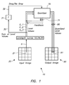
- Fig. 1 diagrammatically shows an embodiment in accordance with the invention; and
- Fig. 2 shows a set of levelsplit curves as used by this embodiment.
-
- In a preferred embodiment of the invention, a set of levelsplit curves is used, that define, for each tone value and each level, what fraction of the pixels will be filled by the different levels, i.e. what contribution the different levels make to reproduce a given tone value. In the case of a binary printer the set levelsplit curves may be the set of inksplit curves.
- Fig. 2 shows an example of levelsplit curves for a printing system with three drop sizes (small, medium, large). In diagram 50, the
horizontal axis 51 represents tone value, while thevertical axis 52 represents level value. Each tone value is transformed into a maximum of three level values in this example, as there are three levelsplit curves:curve 53 for the small drop size,curve 54 for medium drop size andcurve 55 for large drop size. For example tone value G is transformed into level values G_1 and G_2. - In this drawing, the tone value and level values are in the
range 0 .. 255. They may of course also be in other ranges; they may also be scaled to the interval [0 .. 1] or to 0 .. 100%, as is generally done in the description below. - These curves may be designed by a user with the help of a user interface, allowing to draw curves or to specify curves by changing a few numbers, such as the start and end point of the different curves, their maximal height, etc. Alternatively they may be generated by a computer program to optimize certain system properties such as grain, ink amount, banding artifacts, etc.
- A levelsplit curve may also be given in the form of a table.
- As discussed above, a level may be realized by a combination of a dot area, corresponding in ink-jet printing to an ink drop size, and a dot density, corresponding in ink-jet printing to an ink density.
- Moreover, a level may also correspond to an overlap of at least two dot area / dot density combinations, as will now be explained.
- Take again the example with 6 levels discussed above:
level 0 = no drop of ink, level 1 = a small drop of light ink, level 2 = a medium drop of light ink, level 3 = a large drop of light ink, level 4 = a medium drop of dark ink, level 5 = a large drop of dark ink. This case may be represented by five levelsplit curves, for levels 1 to 5. We can avoid overlaps of the different levels on a single pixel, by keeping the sum of all curves smaller than or at most equal to one (i.e. 100 %). In case we do want to allow for overlaps, we may achieve this in different ways. - In a first embodiment, the overlaps are defined as additional levels, and we will have a separate curve describing the contribution of such an additional level to the tone value. E.g. in the binary printer example discussed above we may have 4 levels instead of 3:
level 0 = no drop of ink, level 1 = a drop of light ink, level 2 = a drop of dark ink, and now additionally level 3 = a drop of both light and dark ink on top of each other. We will need 3 levelsplit curves in this case. - In a second embodiment, we allow that the sum of the levelsplit curves is larger than 1. E.g. when at a particular tone value we have a contribution of 40% of
level 1 and 70% of level 2, this will result in a 10% overlap of levels 1 and 2 (10% = 40% + 70% - 100%). - In both these embodiments, it is possible to specify the exact amount of overlap between each of the levels. This is an additional advantage of using levelsplit curves. When using the classic inksplit curves with standard error diffusion, the overlap between drops of light ink and dark ink is not controlled entirely by the curves, but depends to a large extent on the details of the error diffusion process. Take for example a case with two inksplit curves, and suppose that for a given tone value, level1 = 20% and level2 = 20%. If now, for both levels, an ED algorithm is used that is sufficiently random (e.g. by providing enough noise, or by changing the threshold value in a random way), then the overlap of both levels will be 0.2 x 0.2 = 0.04 = 4%. If, on the other hand, for both levels identically the same error diffuser is used, without noise, then the same pixels will be set for both levels, so that the overlap will be 20%.
- In a preferred embodiment of the invention, the error diffuser is such that the overlap of the levels on a given pixel is controlled by the levelsplit curves and is independent of the error diffuser. This offers the advantage of full control over the specific contributions of the levels to the tone, as well as full control over the overlap between different levels. Moreover, this control may be done outside of the error diffusion process. The overlap may be controlled for printing devices using only one drop size and inks of different densities, for printing devices using multiple drop sizes and an ink of one density, for printing devices using multiple drop sizes and inks of different densities.
- The advantage of laying the full control of level usage outside of the error diffuser is that the error diffuser is far more adaptable to new situations, e.g. new printer type, new inks, new media, other application. It gives a user the possibility to rule out certain levels that may be responsible for certain artefacts such as banding. It offers the possibility to make other trade-offs between graininess and ink usage for different applications, without changing anything to the error diffusion algorithm.
- Moreover, the percentage of white pixels may be controlled as well. It is equal to 1 minus the sum of the levelsplit curves, when expressed in the interval [0 .. 1].
- The levelsplit curves may be read from a file or even adapted interactively by a user of the ED.
- In classical multilevel error diffusion, using a multilevel quantiser or multiple thresholds, use of the different levels and their overlaps is only controlled partially and indirectly via manipulation and randomisation of the thresholds, as illustrated already above by the example of the two inksplit curves.
- Fig. 1 shows a
preferred embodiment 10 of the invention, wherein the ED algorithm using the levelsplit curves is as follows. - Suppose we have K levelsplit curves (i.e. K levels other than the one where no ink is applied; K=3 in Fig. 1).
- The
input image 20 contains a plurality ofpixels 21. We scan the image, e.g. in a linewise manner. - For each encountered
pixel 21, we perform the following steps: - Step 1:
- Transform the incoming gray value G to K values G_1,...,G_K by the levelsplit curves.
- Step 2:
- Modify the values G_1,...,G_K by adding the quantization
errors received from neighboring, already processed pixels,
G_1 → G_i + E_i , i=1, ..., K
(this isfeedback 71, performed byquantizer 70, in Fig. 1) - Step 3:
- Calculate the sum S = ∑ G_i of the modified pixel values.
(indicated byreference sign 30 in Fig. 1) - Step 4:
- Find the channel i=imax having the largest value of G_i.
- Step 5:
- Quantization of the values G_i yielding output values O_i:
If S is larger than the threshold T (reference 31 in Fig. 1)
O_i = 1, for i=imax (i.e. set a drop; reference 32)
O_i = 0, for all other i (i.e. no drop of ink; ref. 32)
Else
O_i = 0, for all i - Step 6:
- Diffuse quantization error for all K channels to neighboring, unprocessed pixels (by quantiser 70).
- When allowing sum values of levelsplit curves larger than 1, step 5 above will be replaced by:
- Step 5':
- Quantization of the values G_i yielding output values O_i:
O_i = 0, for all i
While S is larger than the threshold T
O_i = 1, for i=imax
S is replaced by S-1
G_i is replaced by G_i -1
Find the channel i=imax having the largest value of G_i - When the sum of the levelsplit curves is smaller than 2 (= 200%), the above while loop is performed no more than 2 times at most.
- The quantized level values 80 are now used to set
pixel 91 inoutput image 90. - Other embodiments of an ED algorithm that uses the levelsplit curves are as follows. Instead of using the sum S of pixel values, another function f(G_1,...,G_K) may be used. More specifically we may use a linear combination of the G_i, with minor adaptations to the algorithm outlined above.
- Another possibility of changing the algorithm is to group certain levels together (e.g. all levels with a certain drop size, irrespective of their ink density). We can then replace the binary threshold T by a multilevel quantiser. In our example, the output of this quantiser will be No drop/A drop of Light Ink/A drop of Dark Ink/ An overlap of Light and Dark Ink. The second quantiser will then decide over the size of the drop.
- As discussed already above, in a preferred embodiment of the invention, the error diffuser is such that the overlap of the levels on a given pixel is controlled by the levelsplit curves and is independent of the error diffuser.
- The following example illustrates this: with two different sets of levelsplit curves, the contributions of two levels to reproduce a given tone value are the same, but the overlap of the levels is different, while nothing is changed to the error diffuser. The first set of curves contains two curves, for levels L1 and L2, so that their sum is at most equal to 100% (these curves represent a combination of a dot density and a dot area, not an overlap). As explained before, the overlap is thus zero. The second set is based on the first set and contains three curves, as follows:
- It is also possible to specify that a particular overlap of two levels is to be zero, or that more overlaps, even all overlaps of all levels are to be zero; this may be advantageous with respect to drying (in these cases, a level means a combination of a dot area and a dot density, not an overlap of two or more of such combinations).
- The present invention can be applied to black and white printing devices and to color printing devices. It is especially suitable for ink-jet printing, but may also be applied to other printing techniques (such as electrophotography). Also, white ink may be used, which may be together with a combination of other inks, e.g. CMYK inks, and possibly on a non-white (e.g. black) receiving substrate.
- Those skilled in the art will appreciate that numerous modifications and variations may be made to the embodiments disclosed above without departing from the scope of the present invention.
-
- 10 :
- embodiment
- 20 :
- input image
- 21 :
- input pixel
- 30 :
- sum
- 31 :
- threshold
- 32 :
- drop/no drop
- G :
- tone value
- G_1
- level value
- G_2:
- level value
- G_3:
- level value
- 50 :
- diagram
- 51 :
- axis
- 52 :
- axis
- 53 :
- levelsplit curve
- 54 :
- levelsplit curve
- 55 :
- levelsplit curve
- 70 :
- quantizer
- 71 :
- feedback
- 80 :
- quantized level values
- 90 :
- output image
- 91 :
- output pixel
Claims (10)
- A method for processing a digitized continuous tone image (20) for reproducing said image (20) by a printing device, wherein said image (20) comprises a plurality of pixels (21), the method comprising the steps of:characterized in that a fraction of said output pixels (91) that is to be filled by an overlap of levels depends on said level values (G_1 - G_K) and is independent of said error diffuser, said overlap of levels being an overlap of at least a first level and a second level, wherein said first level is a first said combination of a first dot density and a first dot area and said second level is a second said combination of a second dot density and a second dot area.inputting a tone value (G) of an input pixel (21) of said image (20);applying a plurality (K) of levelsplit curves (53-55) to said tone value (G), thus obtaining a plurality of level values (G_1 - G_K), wherein each specific levelsplit curve (53-55) out of said plurality of levelsplit curves corresponds to a level defined byand wherein each said specific levelsplit curve defines, for said tone value (G) of said input pixel (21), which fraction of output pixels (91) of said image when reproduced by said printing device is to be filled by the level corresponding to said specific levelsplit curve when reproducing said tone value (G);(i) a combination of a dot density and a dot area, to be applied by said printing device to a receiving substrate for reproducing said image; or(ii) an overlap of a plurality of such combinations;inputting said plurality of level values (G_1 - G_K) to an error diffuser for obtaining an output pixel value of a said output pixel (91) for reproducing said image;
- The method according to claim 1 further comprising the step of reading said plurality of levelsplit curves from a file.
- The method according to claim 1 further comprising the step of inputting said plurality of levelsplit curves through a user interface.
- The method according to any one of claims 1 to 3 further comprising the step of providing a set of said levelsplit curves (53-55) for setting said overlap of levels to zero.
- The method according to any one of claims 1 to 3 further comprising the step of providing another set of said levelsplit curves (53-55) for setting all overlaps of all levels to zero.
- The method according to any one of the preceding claims further comprising the step of printing said image on said receiving substrate, thus obtaining a printed material.
- The printed material obtained by the method according to claim 6.
- An ink-jet printer comprising means for performing the method according to claim 1, wherein said dot density is an ink density of said ink-jet printer and said dot area is an ink drop size of said ink-jet printer.
- A computer program comprising computer program code means adapted to perform the method according to any one of claims 1 to 3 when said program is run on a computer.
- A computer readable medium comprising program code adapted to carry out the method according to any one of claims 1 to 3 when run on a computer.
Priority Applications (1)
| Application Number | Priority Date | Filing Date | Title |
|---|---|---|---|
| EP20050103624 EP1592226B1 (en) | 2004-04-30 | 2005-05-02 | Method for multilevel error diffusion with predetermined level split ratios |
Applications Claiming Priority (3)
| Application Number | Priority Date | Filing Date | Title |
|---|---|---|---|
| EP04101858 | 2004-04-30 | ||
| EP04101858 | 2004-04-30 | ||
| EP20050103624 EP1592226B1 (en) | 2004-04-30 | 2005-05-02 | Method for multilevel error diffusion with predetermined level split ratios |
Publications (2)
| Publication Number | Publication Date |
|---|---|
| EP1592226A1 true EP1592226A1 (en) | 2005-11-02 |
| EP1592226B1 EP1592226B1 (en) | 2007-08-15 |
Family
ID=35445661
Family Applications (1)
| Application Number | Title | Priority Date | Filing Date |
|---|---|---|---|
| EP20050103624 Ceased EP1592226B1 (en) | 2004-04-30 | 2005-05-02 | Method for multilevel error diffusion with predetermined level split ratios |
Country Status (1)
| Country | Link |
|---|---|
| EP (1) | EP1592226B1 (en) |
Cited By (4)
| Publication number | Priority date | Publication date | Assignee | Title |
|---|---|---|---|---|
| WO2009031165A1 (en) * | 2007-09-03 | 2009-03-12 | Telecom Italia S.P.A. | Image processing method and apparatus |
| EP2677731A3 (en) * | 2012-06-19 | 2015-12-23 | SCREEN Holdings Co., Ltd. | Image data generation method, image recording method, image data generation apparatus, and image recording apparatus |
| US11425277B2 (en) | 2017-10-02 | 2022-08-23 | Agfa Nv | Method of manufacturing decorative panels |
| WO2023187096A1 (en) | 2022-04-01 | 2023-10-05 | Agfa Offset Bv | Rendering a color separation |
Citations (7)
| Publication number | Priority date | Publication date | Assignee | Title |
|---|---|---|---|---|
| US5805178A (en) * | 1995-04-12 | 1998-09-08 | Eastman Kodak Company | Ink jet halftoning with different ink concentrations |
| US5963714A (en) * | 1996-11-15 | 1999-10-05 | Seiko Epson Corporation | Multicolor and mixed-mode halftoning |
| US6109720A (en) * | 1993-04-28 | 2000-08-29 | Canon Kabushiki Kaisha | Method and apparatus for ink-jet recording with inks having different densities |
| US20020051151A1 (en) * | 2000-03-02 | 2002-05-02 | Seiji Ohshima | Image processing apparatus and method to reduce gray levels of image |
| US20020181987A1 (en) * | 2000-10-06 | 2002-12-05 | Toshiaki Kakutani | Image processing device, printing control device, image processing method and recorded medium |
| US20030021470A1 (en) * | 2000-10-06 | 2003-01-30 | Toshiaki Kakutani | Image processing device, image processing method,recorded medium, and program |
| US20030179410A1 (en) * | 2002-03-21 | 2003-09-25 | Velde Koen Van De | Multilevel colour error-diffusion providing reduced sensitivity to printing process variability errors |
-
2005
- 2005-05-02 EP EP20050103624 patent/EP1592226B1/en not_active Ceased
Patent Citations (7)
| Publication number | Priority date | Publication date | Assignee | Title |
|---|---|---|---|---|
| US6109720A (en) * | 1993-04-28 | 2000-08-29 | Canon Kabushiki Kaisha | Method and apparatus for ink-jet recording with inks having different densities |
| US5805178A (en) * | 1995-04-12 | 1998-09-08 | Eastman Kodak Company | Ink jet halftoning with different ink concentrations |
| US5963714A (en) * | 1996-11-15 | 1999-10-05 | Seiko Epson Corporation | Multicolor and mixed-mode halftoning |
| US20020051151A1 (en) * | 2000-03-02 | 2002-05-02 | Seiji Ohshima | Image processing apparatus and method to reduce gray levels of image |
| US20020181987A1 (en) * | 2000-10-06 | 2002-12-05 | Toshiaki Kakutani | Image processing device, printing control device, image processing method and recorded medium |
| US20030021470A1 (en) * | 2000-10-06 | 2003-01-30 | Toshiaki Kakutani | Image processing device, image processing method,recorded medium, and program |
| US20030179410A1 (en) * | 2002-03-21 | 2003-09-25 | Velde Koen Van De | Multilevel colour error-diffusion providing reduced sensitivity to printing process variability errors |
Cited By (6)
| Publication number | Priority date | Publication date | Assignee | Title |
|---|---|---|---|---|
| WO2009031165A1 (en) * | 2007-09-03 | 2009-03-12 | Telecom Italia S.P.A. | Image processing method and apparatus |
| US20100202023A1 (en) * | 2007-09-03 | 2010-08-12 | Telecom Italia S.P.A. | Image Processing Method and Apparatus |
| US8824013B2 (en) | 2007-09-03 | 2014-09-02 | Sicpa Holding Sa | Error diffusion halftoning method for dark ink and light ink channels, based on a measure of solvent quantity that should be ejected for each pixel, and apparatus that performs the halftoning method |
| EP2677731A3 (en) * | 2012-06-19 | 2015-12-23 | SCREEN Holdings Co., Ltd. | Image data generation method, image recording method, image data generation apparatus, and image recording apparatus |
| US11425277B2 (en) | 2017-10-02 | 2022-08-23 | Agfa Nv | Method of manufacturing decorative panels |
| WO2023187096A1 (en) | 2022-04-01 | 2023-10-05 | Agfa Offset Bv | Rendering a color separation |
Also Published As
| Publication number | Publication date |
|---|---|
| EP1592226B1 (en) | 2007-08-15 |
Similar Documents
| Publication | Publication Date | Title |
|---|---|---|
| US5757976A (en) | Adaptive filtering and thresholding arrangement for reducing graininess of images | |
| US20100165413A1 (en) | Image Processing Apparatus and Image Processing Method for Supressing Jaggies in the Edge Portions of Image | |
| US8405877B2 (en) | Laser print apparatus with dual half tones | |
| US7580569B2 (en) | Method and system for generating contone encoded binary print data streams | |
| JP4149269B2 (en) | Error diffusion method and system using intermediate dots | |
| US7136189B2 (en) | Color halftoning using a multi-level successive-filling halftone screening algorithm | |
| JP2004187193A (en) | Image processing apparatus | |
| US8208175B2 (en) | Blended error diffusion and adaptive quantization | |
| US7116445B2 (en) | Image forming apparatus and image forming method | |
| US6844941B1 (en) | Color halftoning using a single successive-filling halftone screen | |
| JP6193594B2 (en) | Image processing apparatus, image processing method, image processing system, and program | |
| JP3990783B2 (en) | Image processing apparatus and image processing method | |
| US6873440B2 (en) | Multibit screening of print documents in a PDL environment | |
| US6851783B1 (en) | Replacement halftoning | |
| US20040257619A1 (en) | Method for color rendering using scanned halftone classification | |
| EP1592226B1 (en) | Method for multilevel error diffusion with predetermined level split ratios | |
| US6956673B2 (en) | Image processing apparatus and method to reduce gray levels of image | |
| US7518753B2 (en) | Full control multilevel error diffusion | |
| JP4333990B2 (en) | Inkjet recording apparatus and inkjet recording method | |
| JP3732470B2 (en) | Image processing apparatus, image recording apparatus, and program | |
| JP2004135317A (en) | Color image processing apparatus and color image processing method | |
| CN1867033A (en) | Multi-configured halftone system | |
| JPH11320919A (en) | Image output device | |
| JP2002320089A (en) | Image processing apparatus, image forming apparatus, image processing method, program, and recording medium | |
| JPH11138862A (en) | Image output device |
Legal Events
| Date | Code | Title | Description |
|---|---|---|---|
| PUAI | Public reference made under article 153(3) epc to a published international application that has entered the european phase |
Free format text: ORIGINAL CODE: 0009012 |
|
| AK | Designated contracting states |
Kind code of ref document: A1 Designated state(s): AT BE BG CH CY CZ DE DK EE ES FI FR GB GR HU IE IS IT LI LT LU MC NL PL PT RO SE SI SK TR |
|
| AX | Request for extension of the european patent |
Extension state: AL BA HR LV MK YU |
|
| 17P | Request for examination filed |
Effective date: 20060502 |
|
| AKX | Designation fees paid |
Designated state(s): DE FR GB |
|
| 17Q | First examination report despatched |
Effective date: 20060901 |
|
| RAP1 | Party data changed (applicant data changed or rights of an application transferred) |
Owner name: AGFA GRAPHICS N.V. |
|
| GRAP | Despatch of communication of intention to grant a patent |
Free format text: ORIGINAL CODE: EPIDOSNIGR1 |
|
| GRAS | Grant fee paid |
Free format text: ORIGINAL CODE: EPIDOSNIGR3 |
|
| GRAA | (expected) grant |
Free format text: ORIGINAL CODE: 0009210 |
|
| AK | Designated contracting states |
Kind code of ref document: B1 Designated state(s): DE FR GB |
|
| REG | Reference to a national code |
Ref country code: GB Ref legal event code: FG4D |
|
| RIN1 | Information on inventor provided before grant (corrected) |
Inventor name: VANDE VELDE, KOENAGFA-GEVAERT |
|
| REF | Corresponds to: |
Ref document number: 602005001968 Country of ref document: DE Date of ref document: 20070927 Kind code of ref document: P |
|
| ET | Fr: translation filed | ||
| PLBE | No opposition filed within time limit |
Free format text: ORIGINAL CODE: 0009261 |
|
| STAA | Information on the status of an ep patent application or granted ep patent |
Free format text: STATUS: NO OPPOSITION FILED WITHIN TIME LIMIT |
|
| 26N | No opposition filed |
Effective date: 20080516 |
|
| REG | Reference to a national code |
Ref country code: FR Ref legal event code: PLFP Year of fee payment: 12 |
|
| REG | Reference to a national code |
Ref country code: FR Ref legal event code: PLFP Year of fee payment: 13 |
|
| REG | Reference to a national code |
Ref country code: DE Ref legal event code: R081 Ref document number: 602005001968 Country of ref document: DE Owner name: AGFA NV, BE Free format text: FORMER OWNER: AGFA GRAPHICS N.V., MORTSEL, BE |
|
| REG | Reference to a national code |
Ref country code: FR Ref legal event code: PLFP Year of fee payment: 14 |
|
| REG | Reference to a national code |
Ref country code: FR Ref legal event code: CD Owner name: AGFA NV, BE Effective date: 20180628 |
|
| PGFP | Annual fee paid to national office [announced via postgrant information from national office to epo] |
Ref country code: GB Payment date: 20220421 Year of fee payment: 18 Ref country code: FR Payment date: 20220421 Year of fee payment: 18 Ref country code: DE Payment date: 20220420 Year of fee payment: 18 |
|
| REG | Reference to a national code |
Ref country code: DE Ref legal event code: R119 Ref document number: 602005001968 Country of ref document: DE |
|
| GBPC | Gb: european patent ceased through non-payment of renewal fee |
Effective date: 20230502 |
|
| PG25 | Lapsed in a contracting state [announced via postgrant information from national office to epo] |
Ref country code: DE Free format text: LAPSE BECAUSE OF NON-PAYMENT OF DUE FEES Effective date: 20231201 Ref country code: GB Free format text: LAPSE BECAUSE OF NON-PAYMENT OF DUE FEES Effective date: 20230502 |
|
| PG25 | Lapsed in a contracting state [announced via postgrant information from national office to epo] |
Ref country code: FR Free format text: LAPSE BECAUSE OF NON-PAYMENT OF DUE FEES Effective date: 20230531 |