EP1592210A2 - LED indicating the roaming area for a mobile phone - Google Patents
LED indicating the roaming area for a mobile phone Download PDFInfo
- Publication number
- EP1592210A2 EP1592210A2 EP05008655A EP05008655A EP1592210A2 EP 1592210 A2 EP1592210 A2 EP 1592210A2 EP 05008655 A EP05008655 A EP 05008655A EP 05008655 A EP05008655 A EP 05008655A EP 1592210 A2 EP1592210 A2 EP 1592210A2
- Authority
- EP
- European Patent Office
- Prior art keywords
- light emitting
- service area
- roaming
- control signal
- mobile telecommunication
- Prior art date
- Legal status (The legal status is an assumption and is not a legal conclusion. Google has not performed a legal analysis and makes no representation as to the accuracy of the status listed.)
- Ceased
Links
Images


Classifications
-
- A—HUMAN NECESSITIES
- A21—BAKING; EDIBLE DOUGHS
- A21B—BAKERS' OVENS; MACHINES OR EQUIPMENT FOR BAKING
- A21B5/00—Baking apparatus for special goods; Other baking apparatus
- A21B5/08—Apparatus for baking in baking fat or oil, e.g. for making doughnuts
-
- A—HUMAN NECESSITIES
- A21—BAKING; EDIBLE DOUGHS
- A21B—BAKERS' OVENS; MACHINES OR EQUIPMENT FOR BAKING
- A21B3/00—Parts or accessories of ovens
- A21B3/13—Baking-tins; Baking forms
- A21B3/133—Baking-tins; Baking forms for making bread
- A21B3/134—Multiple bread pans
-
- H—ELECTRICITY
- H04—ELECTRIC COMMUNICATION TECHNIQUE
- H04M—TELEPHONIC COMMUNICATION
- H04M1/00—Substation equipment, e.g. for use by subscribers
- H04M1/72—Mobile telephones; Cordless telephones, i.e. devices for establishing wireless links to base stations without route selection
- H04M1/724—User interfaces specially adapted for cordless or mobile telephones
- H04M1/72448—User interfaces specially adapted for cordless or mobile telephones with means for adapting the functionality of the device according to specific conditions
- H04M1/72457—User interfaces specially adapted for cordless or mobile telephones with means for adapting the functionality of the device according to specific conditions according to geographic location
-
- H—ELECTRICITY
- H04—ELECTRIC COMMUNICATION TECHNIQUE
- H04M—TELEPHONIC COMMUNICATION
- H04M1/00—Substation equipment, e.g. for use by subscribers
- H04M1/72—Mobile telephones; Cordless telephones, i.e. devices for establishing wireless links to base stations without route selection
- H04M1/725—Cordless telephones
- H04M1/72502—Cordless telephones with one base station connected to a single line
- H04M1/72516—Cordless telephones with one base station connected to a single line with means for out-of-range alerting
-
- H—ELECTRICITY
- H04—ELECTRIC COMMUNICATION TECHNIQUE
- H04M—TELEPHONIC COMMUNICATION
- H04M1/00—Substation equipment, e.g. for use by subscribers
- H04M1/02—Constructional features of telephone sets
- H04M1/22—Illumination; Arrangements for improving the visibility of characters on dials
-
- Y—GENERAL TAGGING OF NEW TECHNOLOGICAL DEVELOPMENTS; GENERAL TAGGING OF CROSS-SECTIONAL TECHNOLOGIES SPANNING OVER SEVERAL SECTIONS OF THE IPC; TECHNICAL SUBJECTS COVERED BY FORMER USPC CROSS-REFERENCE ART COLLECTIONS [XRACs] AND DIGESTS
- Y02—TECHNOLOGIES OR APPLICATIONS FOR MITIGATION OR ADAPTATION AGAINST CLIMATE CHANGE
- Y02D—CLIMATE CHANGE MITIGATION TECHNOLOGIES IN INFORMATION AND COMMUNICATION TECHNOLOGIES [ICT], I.E. INFORMATION AND COMMUNICATION TECHNOLOGIES AIMING AT THE REDUCTION OF THEIR OWN ENERGY USE
- Y02D30/00—Reducing energy consumption in communication networks
- Y02D30/70—Reducing energy consumption in communication networks in wireless communication networks
Definitions
- the present invention relates to a mobile telecommunication device, and more particularly, to a roaming service area indicating device for a mobile telecommunication device.
- the present invention is suitable for a wide scope of applications, it is particularly suitable for reducing the amount of power consumed for indicating the roaming service area.
- a user In order to receive a telecommunication service using a mobile telecommunication device, a user must be subscribed to at least one mobile telecommunication service provider.
- a wide range of mobile telecommunication service providers has cooperative agreements to provide each other's customers, who travel beyond the boundaries of their originally subscribed service area, with services provided by the local mobile telecommunication service providers of the corresponding area, at which the traveling user is located.
- a roaming service relates to providing the user with the desired communication service at a local area service rate, even when the user travels outside the scope of the service network of the service provider to which the user is subscribed.
- a display in the mobile telecommunication device indicates whether or not the roaming service is being carried out. More specifically, the indication is shown in the liquid crystal display (LCD) of the communication device.
- LCD liquid crystal display
- the user can verify whether he or she is presently in a roaming service area or in the subscribed service provider area (hereinafter referred to as "home service area").
- home service area the subscribed service provider area
- the roaming service area is indicated only through the LCD of the device. Therefore, when the communication device is a folder type having only a single LCD part, the user is required to open the folder of the communication device in order to verify whether he or she is in a roaming service area. In case of a folder type mobile communication device having a dual LCD, power should be applied to the backlight of the LCD in order to allow the user to verify the service area.
- the present invention is directed to a roaming service area indicating device for a mobile telecommunication device that substantially obviates one or more problems due to limitations and disadvantages of the related art.
- An object of the present invention is to provide a roaming service area indicating device for a mobile telecommunication device that can reduce the amount of power consumed for indicating the roaming service area.
- a roaming service area indicating device in a mobile telecommunication device includes a mobile station modem outputting a roaming indication control signal depending upon a present location of the mobile telecommunication device, a switching circuit performing switching operations in accordance with the roaming indication control signal outputted from the mobile station modem, and a light emitting part being activated in accordance with an operation result of the switching circuit.
- the light emitting part is formed of first and second light emitting diodes. And, each of the light emitting diodes emits a color different from one another.
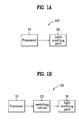
- FIG. 1 illustrates a block diagram showing a structure of the roaming service area indicating device for a mobile telecommunication device according to the present invention
- FIG. 2 illustrates a schematic diagram showing the block diagram of FIG. 1 in more detail.
- FIG. 1 illustrates a block diagram showing a structure of the roaming service area indicating device for a mobile telecommunication device according to the present invention.
- the roaming service area indicating device for the mobile telecommunication device includes a mobile station modem (MSM) 10 outputting a roaming indication control signal depending upon a present location of the mobile telecommunication device, a switching circuit 20 performing switching operations depending upon the roaming indication control signal outputted from the mobile station modem 10, and a light emitting part 30 operating in accordance with the operation results of the switching circuits 20.
- MSM mobile station modem
- FIG. 2 illustrates a schematic diagram showing the block diagram of FIG. 1 in more detail.
- the mobile station modem 10 has a plurality of output terminals. However, only two output terminals (E1 and E2) required for describing the operation of the present invention are illustrated in the example shown in FIG. 2 for simplicity.
- the switching circuit 20 is formed of first and second switching transistors Q1 and Q2.
- the first and second output signals E1 and E2 of the modem 10 are transmitted to a base terminal of each of the first and second switching transistors Q1 and Q2, which form the switching circuit 20.
- a collector terminal for each of the first and second switching transistors Q1 and Q2 is connected to the light emitting part 30.
- the light emitting part 30 is formed of first and second light emitting diodes D1 and D2.
- the collector terminal of the first switching transistor Q1 is connected to the first light emitting diode D1.
- the collector terminal of the second switching transistor Q2 is connected to the second light emitting diode D2.
- first and second light emitting diode enable control signals LED Enable 1 and LED Enable 2 are outputted.
- the device selects an accessible system and channel from where the device is located.
- the mobile telecommunication device compares the selected system and channel with its preferred roaming list (PRL).
- PRL preferred roaming list
- the selected system and channel correspond to a home system
- the first light emitting diode enable control signal E1 is outputted at a high state
- the second light emitting diode enable control signal E2 is outputted at a low state.
- the first light emitting diode enable control signal E1 is transmitted to the base terminal of the first switching terminal Q1. Accordingly, the power is supplied to the first light emitting diode D1. Subsequently, depending upon whether the power is supplied or not, the first light emitting diode D1 is turned either on or off.
- the second light emitting diode enable control signal E2 is outputted at a high state, and the first light emitting diode enable control signal E1 is outputted at a low state.
- the second light emitting diode enable control signal E2 is transmitted to the base terminal of the second switching transistor Q2. Accordingly, the power is supplied to the second light emitting diode D2. Subsequently, depending upon whether the power is supplied or not, the second light emitting diode D2 is turned either on or off.
- the user of the mobile telecommunication device can be aware of whether he or she is presently located at a home service area or a roaming service area. More specifically, the first light emitting diode D1 may blink when the user is determined to be in the home service area, whereas the second light emitting diode D2 may blink when the user is determined to be in the roaming service area. Alternatively, the first light emitting diode D1 may blink when the user is determined to be in the roaming service area, and the second light emitting diode D2 may blink when the user is determined to be in the home service area.
- "home” and "roaming" should be indicated on a set portion near each light emitting diode formed in the indicator, respectively.
- the light emitting diode can be activated, when in the home service area or the roaming service area, in a wide range of forms. For example, each of the areas can be indicated in different colors. Alternatively, the light emitting diode can remain inactivated in the home service area, whereas either the first light emitting diode or the second light emitting diode is activated in the roaming service area.
- the roaming service area indicating device for the mobile telecommunication device indicates the type of service area through the indicator.
- the user can verify whether or not he or she is in a roaming service area.
- the backlight of the liquid crystal display is not required to be turned on, thereby extending the usage time of the battery of the mobile telecommunication device.
- the roaming service area indicating device for the mobile telecommunication device according to the present invention does not provide particular efficiency when used in the originally subscribed service area (i.e., the home service area), the present invention can provide considerable efficiency when used in an area outside the home service area (i.e., the roaming service area) requiring a different service charge rate.
Landscapes
- Engineering & Computer Science (AREA)
- Computer Networks & Wireless Communication (AREA)
- Signal Processing (AREA)
- Life Sciences & Earth Sciences (AREA)
- Food Science & Technology (AREA)
- Environmental & Geological Engineering (AREA)
- Human Computer Interaction (AREA)
- Chemical & Material Sciences (AREA)
- Oil, Petroleum & Natural Gas (AREA)
- Telephone Function (AREA)
- Mobile Radio Communication Systems (AREA)
Abstract
Description
Claims (5)
- A roaming service area indicating device in a mobile telecommunication device, comprising:a mobile station modem outputting a roaming indication control signal depending upon a present location of the mobile telecommunication device;a switching circuit performing switching operations in accordance with the roaming indication control signal outputted from the mobile station modem; anda light emitting part being activated in accordance with an operation result of the switching circuit.
- The device according to claim 1, wherein the switching circuit is formed of first and second switching transistors being switched in accordance with the control signal of the mobile station modem.
- The device according to claim 2, wherein each of the switching transistors is respectively supplied with the control signal of the mobile station modem through each base terminal, thereby carrying out switching operations.
- The device according to claim 1, wherein the light emitting part is formed of first and second light emitting diodes.
- The device according to claim 4, wherein each of the light emitting diodes emits a color different from one another.
Applications Claiming Priority (2)
| Application Number | Priority Date | Filing Date | Title |
|---|---|---|---|
| KR1020040027025A KR100606716B1 (en) | 2004-04-20 | 2004-04-20 | Roaming area indicator of mobile communication terminal |
| KR2004027025 | 2004-04-20 |
Publications (2)
| Publication Number | Publication Date |
|---|---|
| EP1592210A2 true EP1592210A2 (en) | 2005-11-02 |
| EP1592210A3 EP1592210A3 (en) | 2005-11-16 |
Family
ID=34935467
Family Applications (1)
| Application Number | Title | Priority Date | Filing Date |
|---|---|---|---|
| EP05008655A Ceased EP1592210A3 (en) | 2004-04-20 | 2005-04-20 | LED indicating the roaming area for a mobile phone |
Country Status (4)
| Country | Link |
|---|---|
| US (1) | US20050233747A1 (en) |
| EP (1) | EP1592210A3 (en) |
| KR (1) | KR100606716B1 (en) |
| CN (1) | CN1691813A (en) |
Families Citing this family (1)
| Publication number | Priority date | Publication date | Assignee | Title |
|---|---|---|---|---|
| CN107968677B (en) * | 2016-10-20 | 2021-03-19 | 株式会社理光 | Relay device, method and system for directional propagation of wireless signals |
Family Cites Families (12)
| Publication number | Priority date | Publication date | Assignee | Title |
|---|---|---|---|---|
| US3987401A (en) * | 1974-12-31 | 1976-10-19 | Motorola, Inc. | Indicating system using multicolor light emitting diodes |
| US5444765A (en) * | 1992-03-23 | 1995-08-22 | Kabushiki Kaisha Toshiba | Radio telephone apparatus having a service area confirmation |
| US5255307A (en) * | 1992-05-07 | 1993-10-19 | Sony Electronics Inc. | Status indicator control for cellular mobile telephone system |
| US6151515A (en) * | 1994-09-14 | 2000-11-21 | Mitsubishi Wireless Communications Inc. | 7, 8 segment display for mobile radio telephone |
| US6125286A (en) * | 1997-06-05 | 2000-09-26 | Motorola, Inc. | Communication device having multiple displays and method of operating the same |
| US6438390B1 (en) * | 1999-05-06 | 2002-08-20 | Motorola, Inc. | Plural status indication control method suitable for use in a communication device |
| JP2001053838A (en) * | 1999-08-10 | 2001-02-23 | Nec Saitama Ltd | System and method for displaying in-range and out-range in folded portable telephone device |
| JP4631226B2 (en) * | 2001-07-12 | 2011-02-16 | 日本電気株式会社 | Mobile phone terminal and customization method thereof |
| WO2003017623A2 (en) * | 2001-08-17 | 2003-02-27 | Wildseed, Ltd. | Visualization supplemented wireless mobile telephony |
| TW575828B (en) * | 2002-05-07 | 2004-02-11 | Giga Byte Tech Co Ltd | Method for directly displaying signal intensity and the device thereof |
| EP1387561A1 (en) * | 2002-07-29 | 2004-02-04 | Fuji Photo Film Co., Ltd. | Wireless communication apparatus and imaging apparatus |
| KR100706384B1 (en) * | 2004-10-04 | 2007-04-10 | 주식회사 팬택앤큐리텔 | Mobile communication terminal and method providing emergency call function |
-
2004
- 2004-04-20 KR KR1020040027025A patent/KR100606716B1/en not_active Expired - Fee Related
-
2005
- 2005-04-19 US US11/110,339 patent/US20050233747A1/en not_active Abandoned
- 2005-04-20 CN CNA2005100762523A patent/CN1691813A/en active Pending
- 2005-04-20 EP EP05008655A patent/EP1592210A3/en not_active Ceased
Also Published As
| Publication number | Publication date |
|---|---|
| KR100606716B1 (en) | 2006-08-01 |
| KR20050101811A (en) | 2005-10-25 |
| CN1691813A (en) | 2005-11-02 |
| US20050233747A1 (en) | 2005-10-20 |
| EP1592210A3 (en) | 2005-11-16 |
Similar Documents
| Publication | Publication Date | Title |
|---|---|---|
| CN1894982B (en) | Multi-mode wireless communication device and method therefor | |
| ES2306503T3 (en) | IMPROVED GSM CELL TERMINAL. | |
| US8554219B2 (en) | Method of selecting a network by a mobile apparatus | |
| RU2292667C2 (en) | Method for providing and synchronizing preferred roaming list and roaming indicator | |
| KR20090048249A (en) | Method and apparatus for speed dial divided by country / business in mobile communication terminal | |
| ATE283616T1 (en) | NETWORK ARCHITECTURE FOR MOBILE COMMUNICATIONS NETWORK WITH BILLING MODULE FOR SHARED EQUIPMENT | |
| US8503350B2 (en) | Wireless communication system | |
| CN106792491B (en) | Network sharing method and mobile terminal based on dual card | |
| CN101984729A (en) | Communication method and device of dual network dual standby terminal | |
| CN105721699A (en) | Method and system for switching driving mode of mobile terminal | |
| CN105848235A (en) | Communication control method and device | |
| CN105611595A (en) | Cell selection residing method based on 5G fusion same-coverage network | |
| US20060073855A1 (en) | Single point notification for a mobile device | |
| GB2375920A (en) | Method of billing for communications which rewards users for operating their communications devices in relay operating mode | |
| EP1592210A2 (en) | LED indicating the roaming area for a mobile phone | |
| US20080113693A1 (en) | Apparatus and method for controlling electric power of battery according to received signal strength indicator of dual band dual mode terminal | |
| CN108966300A (en) | A kind of bimodulus mould group method for switching network, apparatus and system | |
| CN108449764A (en) | Network connection control method, computer readable storage medium and intelligent terminal | |
| US20150281941A1 (en) | Terminal device and charge prompting method thereof | |
| US20110086621A1 (en) | Method and apparatus for indicating operation state in mobile terminal | |
| CN106603813A (en) | Application program response and setting method and device | |
| KR20030065123A (en) | Time displaying method at roaming for mobile phone | |
| KR100565280B1 (en) | Combined Cell Phone / Wireless Phone | |
| CN101150844A (en) | A method for realizing network handover by a dual-mode mobile terminal | |
| KR200179160Y1 (en) | Communication possible area display device in mobile terminal |
Legal Events
| Date | Code | Title | Description |
|---|---|---|---|
| PUAI | Public reference made under article 153(3) epc to a published international application that has entered the european phase |
Free format text: ORIGINAL CODE: 0009012 |
|
| PUAL | Search report despatched |
Free format text: ORIGINAL CODE: 0009013 |
|
| AK | Designated contracting states |
Kind code of ref document: A2 Designated state(s): AT BE BG CH CY CZ DE DK EE ES FI FR GB GR HU IE IS IT LI LT LU MC NL PL PT RO SE SI SK TR |
|
| AX | Request for extension of the european patent |
Extension state: AL BA HR LV MK YU |
|
| AK | Designated contracting states |
Kind code of ref document: A3 Designated state(s): AT BE BG CH CY CZ DE DK EE ES FI FR GB GR HU IE IS IT LI LT LU MC NL PL PT RO SE SI SK TR |
|
| AX | Request for extension of the european patent |
Extension state: AL BA HR LV MK YU |
|
| 17P | Request for examination filed |
Effective date: 20060403 |
|
| AKX | Designation fees paid |
Designated state(s): AT BE BG CH CY CZ DE DK EE ES FI FR GB GR HU IE IS IT LI LT LU MC NL PL PT RO SE SI SK TR |
|
| 17Q | First examination report despatched |
Effective date: 20060523 |
|
| STAA | Information on the status of an ep patent application or granted ep patent |
Free format text: STATUS: THE APPLICATION HAS BEEN REFUSED |
|
| 18R | Application refused |
Effective date: 20090121 |