EP1592196B1 - System and method for indicating network quality of service capability as a presence attribute of an end-us - Google Patents
System and method for indicating network quality of service capability as a presence attribute of an end-us Download PDFInfo
- Publication number
- EP1592196B1 EP1592196B1 EP05009061A EP05009061A EP1592196B1 EP 1592196 B1 EP1592196 B1 EP 1592196B1 EP 05009061 A EP05009061 A EP 05009061A EP 05009061 A EP05009061 A EP 05009061A EP 1592196 B1 EP1592196 B1 EP 1592196B1
- Authority
- EP
- European Patent Office
- Prior art keywords
- qos
- access network
- server
- network
- user
- Prior art date
- Legal status (The legal status is an assumption and is not a legal conclusion. Google has not performed a legal analysis and makes no representation as to the accuracy of the status listed.)
- Expired - Lifetime
Links
- 238000000034 method Methods 0.000 title claims abstract description 17
- 230000000977 initiatory effect Effects 0.000 claims abstract description 9
- 238000004891 communication Methods 0.000 claims description 24
- 239000000523 sample Substances 0.000 claims description 4
- 230000003993 interaction Effects 0.000 description 6
- 239000008186 active pharmaceutical agent Substances 0.000 description 5
- 238000007726 management method Methods 0.000 description 5
- 230000008569 process Effects 0.000 description 4
- 230000002452 interceptive effect Effects 0.000 description 3
- 230000004044 response Effects 0.000 description 3
- 239000003795 chemical substances by application Substances 0.000 description 2
- 238000005259 measurement Methods 0.000 description 2
- 241001669573 Galeorhinus galeus Species 0.000 description 1
- 230000003466 anti-cipated effect Effects 0.000 description 1
- 230000005540 biological transmission Effects 0.000 description 1
- 238000012512 characterization method Methods 0.000 description 1
- 238000010276 construction Methods 0.000 description 1
- 230000007812 deficiency Effects 0.000 description 1
- 238000010586 diagram Methods 0.000 description 1
- 230000000694 effects Effects 0.000 description 1
- 238000005516 engineering process Methods 0.000 description 1
- 239000000543 intermediate Substances 0.000 description 1
- 230000007246 mechanism Effects 0.000 description 1
- 238000012986 modification Methods 0.000 description 1
- 230000004048 modification Effects 0.000 description 1
- 238000012544 monitoring process Methods 0.000 description 1
- 238000012545 processing Methods 0.000 description 1
- 238000013468 resource allocation Methods 0.000 description 1
Images


Classifications
-
- H—ELECTRICITY
- H04—ELECTRIC COMMUNICATION TECHNIQUE
- H04L—TRANSMISSION OF DIGITAL INFORMATION, e.g. TELEGRAPHIC COMMUNICATION
- H04L65/00—Network arrangements, protocols or services for supporting real-time applications in data packet communication
- H04L65/80—Responding to QoS
-
- H—ELECTRICITY
- H04—ELECTRIC COMMUNICATION TECHNIQUE
- H04L—TRANSMISSION OF DIGITAL INFORMATION, e.g. TELEGRAPHIC COMMUNICATION
- H04L47/00—Traffic control in data switching networks
- H04L47/10—Flow control; Congestion control
-
- H—ELECTRICITY
- H04—ELECTRIC COMMUNICATION TECHNIQUE
- H04M—TELEPHONIC COMMUNICATION
- H04M3/00—Automatic or semi-automatic exchanges
- H04M3/42—Systems providing special services or facilities to subscribers
- H04M3/42365—Presence services providing information on the willingness to communicate or the ability to communicate in terms of media capability or network connectivity
- H04M3/42374—Presence services providing information on the willingness to communicate or the ability to communicate in terms of media capability or network connectivity where the information is provided to a monitoring entity such as a potential calling party or a call processing server
-
- H—ELECTRICITY
- H04—ELECTRIC COMMUNICATION TECHNIQUE
- H04L—TRANSMISSION OF DIGITAL INFORMATION, e.g. TELEGRAPHIC COMMUNICATION
- H04L65/00—Network arrangements, protocols or services for supporting real-time applications in data packet communication
- H04L65/1066—Session management
- H04L65/1101—Session protocols
- H04L65/1104—Session initiation protocol [SIP]
Definitions
- the present invention generally relates to presence. More particularly, and not by way of any limitation, the present invention is directed to system and method for indicating network quality of service (“QoS”) capability as an end-user presence attribute.
- QoS network quality of service
- a cell phone, laptop or handheld PC, desktop PC, and the like can identify themselves to the network using a suitable identifier (e.g., username@company.com).
- a suitable identifier e.g., username@company.com.
- Presence refers to, for example, the availability, proximity, activity level or operating state of a user on a network.
- the ability for users to monitor each other's presence is a feature offered in connection with many applications that support network telephony. For example, instant messaging applications such as MSN® or Yahoo® have an "available buddy" feature, in which a user of the application can determine whether select users are available for engaging in communication.
- the data retrieved and returned to the buddy list e.g.
- Presence information is generally maintained by a presence server in the data network, often a dedicated server.
- the presence server supports network telephony protocols such as the Session Initiation Protocol (SIP).
- SIP Session Initiation Protocol
- Users can register their communication devices with the presence server in order to have their presence maintained and to allow various programs on the network to facilitate network telephony services.
- a first device user wishing to detect the presence of a second device user does so by "subscribing" with the presence server, such as via a SIP SUBSCRIBE message.
- the presence server intermediates between the first device user (also known as the watcher or subscriber) and the second device user to facilitate the communication of the second device user's presence information to the first device user.
- QoS Quality of Service
- VoIP voice-over-IP
- Presence-based personal communication is gaining momentum.
- commercial systems implementing presence-based communication technology revolve around simple "buddy list" attributes that display the availability of the communicating parties.
- Trends in next-generation systems are quickly evolving into a rich presence-enabled communication where general capabilities, device information, and other environments of the buddies are becoming important presence attributes.
- None of today's definitions of rich presence information explicitly consider network QoS capability as an attribute.
- a caller initiates a session of an application like on-line gaming and VoIP, he must attempt to infer the QoS capability of the callee access network from information such as the callee's device type and the wired/wireless attachment of the end system to the network. This is by no means an accurate indicator of the QoS state of the underlying IP network between the caller and the callee.
- the watcher In a presence-based communication environment, the watcher tries to infer the QoS capability of the presentity from the end-system information, such as terminal type and the terminal attachment to the network as wired/wireless.
- end-system information such as terminal type and the terminal attachment to the network as wired/wireless.
- end-users In a non-presence-based communication environment, end-users typically have to negotiate for network QoS using complex protocols, like RSVP.
- RSVP complex protocols
- WO 02/093959 A1 discloses a mobile instant messaging and presence service, wherein a client device of the mobile messaging system adds a qualifier to a presence attribute, the qualifier comprising one or more parameters specifying the use of the attribute.
- a client device receiving a presence attribute processes the received presence attribute according to the qualifier parameters in said received attribute.
- US 2003/0120773 A1 discloses a method for monitoring quality of service in a packet-oriented network. Measurement data on the quality of service of a connection is collected by an endpoint of the connection within a given time interval, and the measurement data is then sent for subsequent processing to a registration unit specifically responsible for connections with the endpoint.
- the document XP 015005195 discloses the rich presence information data format for SIP, RPIDS.
- the document XP 002243553 discloses an architectural solution and functionality required for a presence service.
- the present invention is directed to a mechanism for defining and indicating the QoS capability of the presentity to the watcher as a presence attribute.
- One embodiment is an access network according to claim 1.
- Another embodiment is provided in form of a method according to claim 6.
- Another embodiment is a system for providing quality of service (“QoS”) information of an access network according to claim 12.
- QoS quality of service
- An advantageous embodiment comprises a Session Initiation Protocol (“SIP”) server for providing quality of service (“QoS”) information of an access network.
- the SIP server comprises core SIP server functionality; a Simple Network Management Protocol (“SNMP”) client/server (“C/S”) for communicating with the core SIP server functionality; and a Common Open Policy Services protocol (“COPS”) client for communicating with the core SIP server functionality.
- SNMP Simple Network Management Protocol
- COPS Common Open Policy Services protocol
- FIG. 1 depicted therein is a conventional presence application system 100 where a Sender Principal 102 interfaces with a presence user agent (UA) 104 for transmitting presence information regarding a presentity 106.
- An application-specific presence protocol 108 is used for providing presence information to a presence service network (PSN) 110 that is embodied as an IP-based communications network.
- PSN presence service network
- a watcher 112 obtains the presence information using the presence protocol 108, which is provided to a Receiver Principal 116 who interfaces with a watcher user agent (UA) 114 for controlling the watcher 112.
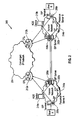
- FIG. 2 is a schematic block diagram of an end-to-end communication system 200 between a first user, designated User A, and a second user, designated User B, across two access networks 202a, 202b, and a converged core network 204.
- the access networks 202a, 202b are assumed to be administrable by a single service provider, such as an Internet Telephony Service Provider ("ITSF") for VoIP service.
- the involved actors in the illustrated scenario include two SIP clients 206a, 206b, two enhanced SIP proxy servers 208a, 208b, two AQS devices 210a, 210b, and the converged core network 204.
- the QoS characteristics of the converged core network 204 may be accessed at the border of the network from edge routers ("ERs") 212a, 212b.
- ERs edge routers
- QoS is set up by a software component in the AQS devices 210a, 210b, running to automate the network-wide QoS configuration and to provision the QoS parameters as bandwidth, delay, jitter, packet loss ratio, etc.
- This component also monitors the QoS-enabled network 204 and issues alerts in response to preassigned threshold values of the network QoS state.
- products are commercially available from such manufacturers as Alcatel, under the name OneTouch QoS, and Cisco, under the name AutoQoS, to configure their respective network gears for VoIP applications. With time, it is conceivable that third-party vendors will develop tools on tope of these products in order to enable multi-vendor QoS configuration across an access network and for applications that go beyond VoIP.
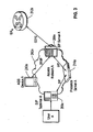
- FIG. 3 illustrates interaction for collecting QoS information for the access network 202a. It will be recognized that, although interaction for collecting QoS information for only the access network 202a is shown and described, the same interaction applies to the access network 202b.
- the presence server 214a develops the network QoS capability attribute of User A from interactions involving the presence server 214a, the enhanced SIP proxy server 208a, the AQS device 210a, and the ER 212a.
- the developed presence attribute of User A can be represented using different methods.
- One straightforward method is to define a technique that creates a match between the integral QoS characterization of the network 202a and the AQS device 210a corresponding to application services and QoS presence attributes of User A.
- AQS tools that are currently commercially available typically define VoIP capability only; however, it is anticipated that future products will indicate clearly QoS capabilities for interactive multimedia, video-streaming, voice, and just data applications.
- one possible method of showing the network QoS attribute of a user, such as User A, to its "buddies" might be to develop codes, such as a color scheme, that illustrate the capabilities of User A in terms of interactive multimedia (e.g., for on-line gaming), video-streaming (e.g., for video broadcasting), voice (e.g., for VoIP), and best effort (e.g., for data).
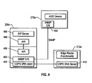
- communications between the SIP terminal 206a, presence server 214a, and enhanced SIP proxy server 208a are SiP-based. Communications between the AQS device 210a and the enhanced SIP proxy server 208a can be Simple Network Management Protocol ("SNMP")-based. Communications between the ER 212a and the enhanced proxy server 208a can be Common Open Policy Service protocol (“COPS”)-based.
- SNMP Simple Network Management Protocol
- COPS Common Open Policy Service protocol
- COPS DRA COPS usage for DiffServ Resource Allocation
- the enhanced SIP proxy server 208a sends inquiries about the state of QoS in the access network 202a through SNMP-based messaging (via the SNMP C/S 400) to an SNMP C/S 408 in the AQS device 210a. Alerts are communicated back to the server 208a from the device 210a in the reverse direction.
- the enhanced SIP proxy server 208a also sends COPS-based messages (via the COPS DRA client 402) to a COPS DRA server 410 of the ER 212a of the converged IP network 204 ( FIG. 2 ) to probe for QoS policy indicators. This is not necessary to indicate QoS capability of the access network 202a.
- the QoS information for the converged IP network can be accessed from the ER 212a and/or from some such central entity, such as a bandwidth broker, that controls the DiffServ cloud.
- This additional information can be used to indicate not only the condition of the access network 202a, but also the end-to-end QoS condition of User A.
- the enhanced SIP proxy server 208a sends the QoS state of the access network 202a and of the converged IP network 204, if available, to the presence server 214a using SIP.
- the presence server 214a then will indicate the network QoS capability of User A to the watcher in User B per the code or color scheme mentioned above using SIP.
- FIG. 5 is a flowchart illustrating operation of the illustrated embodiments for collecting network QoS information in the scenario of FIG. 2 .
- the enhanced SIP proxy server 208a sends SNMP messages to the AQS device 210a to inquire as to the QoS state of the access network 202a.
- the enhanced SIP proxy server 208a receives QoS alerts from the AQS device 210a in response to the inquiries.
- the enhanced SIP proxy server sends COPS messages to the ER 212a to probe for QoS indicators with respect to the converged IP network 204.
- the enhanced SIP proxy server 208a receives a response from the ER 212a advising of the QoS indicators of the converged IP network 204 (if available).
- the enhanced SIP proxy server 208a sends the QoS state of the access network 202a and of the converged IP network 204 (if available) to the presence server 214a using SIP-based messaging.
- the presence server 214a indicates the network QoS of User A to User B using SIP-based messaging.
Landscapes
- Engineering & Computer Science (AREA)
- Signal Processing (AREA)
- Computer Networks & Wireless Communication (AREA)
- Multimedia (AREA)
- Data Exchanges In Wide-Area Networks (AREA)
- Telephonic Communication Services (AREA)
- Sub-Exchange Stations And Push- Button Telephones (AREA)
Abstract
Description
- The present invention generally relates to presence. More particularly, and not by way of any limitation, the present invention is directed to system and method for indicating network quality of service ("QoS") capability as an end-user presence attribute.
- With today's widespread use of the Internet as a major communication medium, data communication devices are now being designed so that they are capable of communicating over packet-switched networks. For instance, telephones, pagers, personal digital assistant devices, cell phones, handheld computers, and even fax machines can now be accessed and controlled from the Internet. Communication over a packet-switched network using communication devices that traditionally communicate over a circuit-switched telecommunications network is generally known as network telephony, or IP telephony when an IP network is involved.
- Various types of user communication devices (e.g., a cell phone, laptop or handheld PC, desktop PC, and the like) can identify themselves to the network using a suitable identifier (e.g., username@company.com). "Presence" refers to, for example, the availability, proximity, activity level or operating state of a user on a network. The ability for users to monitor each other's presence is a feature offered in connection with many applications that support network telephony. For example, instant messaging applications such as MSN® or Yahoo® have an "available buddy" feature, in which a user of the application can determine whether select users are available for engaging in communication. The data retrieved and returned to the buddy list, e.g. "John OFFLINE" or "Susan ACTIVE", is known as "presence information," and is generally maintained by a presence server in the data network, often a dedicated server. Typically, the presence server supports network telephony protocols such as the Session Initiation Protocol (SIP). Users can register their communication devices with the presence server in order to have their presence maintained and to allow various programs on the network to facilitate network telephony services. A first device user wishing to detect the presence of a second device user does so by "subscribing" with the presence server, such as via a SIP SUBSCRIBE message. The presence server intermediates between the first device user (also known as the watcher or subscriber) and the second device user to facilitate the communication of the second device user's presence information to the first device user.
- Additional details about presence and presence modeling are set forth in the Internet Engineering Task Force (IETF) Request for Comment (RFC) 2778 entitled "A model for Presence and Instant Messaging," dated February 2002; RFC 2779 entitled "Instant Messaging / Presence Protocol Requirements," dated February 2002; and Internet-Draft identified as <<draft-schulzrinne-simple-rpids-01 ps>> and entitled "RPIDS - Rich Presence Information Data Format for Presence Based on the Session Initiation Protocol (SIP)," dated February 18, 2003.
- It is commonly known that real-time multimedia interactive communications are very sensitive to the Quality of Service ("QoS") provided by the underlying converged IP network. For example, applications such as on-line gaming and voice-over-IP ("VoIP") cannot be reliably offered as a revenue generating service without being able to provision the network for meeting the bandwidth, delay, and jitter requirements of such traffic.
- Presence-based personal communication is gaining momentum. Currently, commercial systems implementing presence-based communication technology revolve around simple "buddy list" attributes that display the availability of the communicating parties. Trends in next-generation systems are quickly evolving into a rich presence-enabled communication where general capabilities, device information, and other environments of the buddies are becoming important presence attributes. None of today's definitions of rich presence information explicitly consider network QoS capability as an attribute. Before a caller initiates a session of an application like on-line gaming and VoIP, he must attempt to infer the QoS capability of the callee access network from information such as the callee's device type and the wired/wireless attachment of the end system to the network. This is by no means an accurate indicator of the QoS state of the underlying IP network between the caller and the callee.
- Currently, there are basically three solutions to this problem. In a presence-based communication environment, the watcher tries to infer the QoS capability of the presentity from the end-system information, such as terminal type and the terminal attachment to the network as wired/wireless. In a non-presence-based communication environment, end-users typically have to negotiate for network QoS using complex protocols, like RSVP. Finally, the most common practice is to initiate the communications session and hope for the best.
- Each of the so-called "solutions" set forth above suffer deficiencies. The first does not in any way take into account the QoS capability of the network itself. The second has been found not to be widely deployable because of its complexity. Moreover, even if it were to be deployed, the QoS information resulting from the solution is not available before the initiation of the session. The third will work only in an over-provisioned network; otherwise, it is very difficult to deploy a reliable service over such a system.
-
WO 02/093959 A1 -
US 2003/0120773 A1 discloses a method for monitoring quality of service in a packet-oriented network. Measurement data on the quality of service of a connection is collected by an endpoint of the connection within a given time interval, and the measurement data is then sent for subsequent processing to a registration unit specifically responsible for connections with the endpoint. - The document XP 015005195 discloses the rich presence information data format for SIP, RPIDS.
- The document XP 002243553 discloses an architectural solution and functionality required for a presence service.
- Therefore, the present invention is directed to a mechanism for defining and indicating the QoS capability of the presentity to the watcher as a presence attribute. One embodiment is an access network according to claim 1.
- Another embodiment is provided in form of a method according to claim 6.
- Another embodiment is a system for providing quality of service ("QoS") information of an access network according to claim 12.
- An advantageous embodiment comprises a Session Initiation Protocol ("SIP") server for providing quality of service ("QoS") information of an access network. The SIP server comprises core SIP server functionality; a Simple Network Management Protocol ("SNMP") client/server ("C/S") for communicating with the core SIP server functionality; and a Common Open Policy Services protocol ("COPS") client for communicating with the core SIP server functionality.
- A more complete understanding of the present invention may be had by reference to the following Detailed Description when taken in conjunction with the accompanying drawings wherein:
-
FIG. 1 depicts a conventional presence application system; -
FIG. 2 depicts an end-to-end network communications scenario between two users; -
FIG. 3 depicts interactions for collecting network QoS information in the scenario ofFIG. 2 ; -
FIG. 4 depicts a message exchange process between an enhanced proxy server, an AQS device, and an edge router; and -
FIG. 5 depicts a flowchart of the interactions for collecting network QoS information as illustrated inFIG. 3 . - Embodiments of the invention will now be described with reference to various examples of how the invention can best be made and used. Like reference numerals are used throughout the description and several views of the drawings to indicate like or corresponding parts, wherein the various elements are not necessarily drawn to scale. Referring now to the drawings, and more particularly to
FIG. 1 , depicted therein is a conventionalpresence application system 100 where aSender Principal 102 interfaces with a presence user agent (UA) 104 for transmitting presence information regarding apresentity 106. An application-specific presence protocol 108 is used for providing presence information to a presence service network (PSN) 110 that is embodied as an IP-based communications network. At the other end of transmission, awatcher 112 obtains the presence information using thepresence protocol 108, which is provided to aReceiver Principal 116 who interfaces with a watcher user agent (UA) 114 for controlling thewatcher 112. -
FIG. 2 is a schematic block diagram of an end-to-end communication system 200 between a first user, designated User A, and a second user, designated User B, across twoaccess networks core network 204. Theaccess networks SIP clients SIP proxy servers AQS devices core network 204. The QoS characteristics of the convergedcore network 204 may be accessed at the border of the network from edge routers ("ERs") 212a, 212b. - In the
access networks AQS devices network 204 and issues alerts in response to preassigned threshold values of the network QoS state. Presently, products are commercially available from such manufacturers as Alcatel, under the name OneTouch QoS, and Cisco, under the name AutoQoS, to configure their respective network gears for VoIP applications. With time, it is conceivable that third-party vendors will develop tools on tope of these products in order to enable multi-vendor QoS configuration across an access network and for applications that go beyond VoIP. -
FIG. 3 illustrates interaction for collecting QoS information for theaccess network 202a. It will be recognized that, although interaction for collecting QoS information for only theaccess network 202a is shown and described, the same interaction applies to theaccess network 202b. Referring now toFIGs. 2 and3 , at theaccess network 202a, thepresence server 214a develops the network QoS capability attribute of User A from interactions involving thepresence server 214a, the enhancedSIP proxy server 208a, theAQS device 210a, and theER 212a. The developed presence attribute of User A can be represented using different methods. One straightforward method is to define a technique that creates a match between the integral QoS characterization of thenetwork 202a and theAQS device 210a corresponding to application services and QoS presence attributes of User A. - AQS tools that are currently commercially available typically define VoIP capability only; however, it is anticipated that future products will indicate clearly QoS capabilities for interactive multimedia, video-streaming, voice, and just data applications. Hence, one possible method of showing the network QoS attribute of a user, such as User A, to its "buddies" might be to develop codes, such as a color scheme, that illustrate the capabilities of User A in terms of interactive multimedia (e.g., for on-line gaming), video-streaming (e.g., for video broadcasting), voice (e.g., for VoIP), and best effort (e.g., for data).
- As illustrated in
FIG. 3 , communications between theSIP terminal 206a,presence server 214a, and enhancedSIP proxy server 208a are SiP-based. Communications between theAQS device 210a and the enhancedSIP proxy server 208a can be Simple Network Management Protocol ("SNMP")-based. Communications between theER 212a and theenhanced proxy server 208a can be Common Open Policy Service protocol ("COPS")-based. Finally, as illustrated inFIG. 4 , an SNMP client/server ("C/S") 400 and a COPS usage for DiffServ Resource Allocation ("COPS DRA")client 402 that enhance core SIPproxy server functionality 404 can exist as processes outside of the core functionality. As shown inFIG. 4 , thecore functionality 404 communicates with theseprocesses - As best illustrated in
FIG. 4 , typically, the enhancedSIP proxy server 208a sends inquiries about the state of QoS in theaccess network 202a through SNMP-based messaging (via the SNMP C/S 400) to an SNMP C/S 408 in theAQS device 210a. Alerts are communicated back to theserver 208a from thedevice 210a in the reverse direction. The enhancedSIP proxy server 208a also sends COPS-based messages (via the COPS DRA client 402) to aCOPS DRA server 410 of theER 212a of the converged IP network 204 (FIG. 2 ) to probe for QoS policy indicators. This is not necessary to indicate QoS capability of theaccess network 202a. However, in a situation where the convergedIP network 204 is QoS-enabled through a differentiated services ("DiffServ") cloud or a cascade of such clouds, the QoS information for the converged IP network can be accessed from theER 212a and/or from some such central entity, such as a bandwidth broker, that controls the DiffServ cloud. This additional information can be used to indicate not only the condition of theaccess network 202a, but also the end-to-end QoS condition of User A. In particular, the enhancedSIP proxy server 208a sends the QoS state of theaccess network 202a and of the convergedIP network 204, if available, to thepresence server 214a using SIP. Thepresence server 214a then will indicate the network QoS capability of User A to the watcher in User B per the code or color scheme mentioned above using SIP. -
FIG. 5 is a flowchart illustrating operation of the illustrated embodiments for collecting network QoS information in the scenario ofFIG. 2 . In particular, collection of network QoS information for User A will be described for purposes of illustration. Instep 500, the enhancedSIP proxy server 208a sends SNMP messages to theAQS device 210a to inquire as to the QoS state of theaccess network 202a. Instep 502, the enhancedSIP proxy server 208a receives QoS alerts from theAQS device 210a in response to the inquiries. Instep 504, the enhanced SIP proxy server sends COPS messages to theER 212a to probe for QoS indicators with respect to the convergedIP network 204. Inoptional step 506, the enhancedSIP proxy server 208a receives a response from theER 212a advising of the QoS indicators of the converged IP network 204 (if available). - In
step 508, the enhancedSIP proxy server 208a sends the QoS state of theaccess network 202a and of the converged IP network 204 (if available) to thepresence server 214a using SIP-based messaging. Instep 510, thepresence server 214a indicates the network QoS of User A to User B using SIP-based messaging. - As a result, prior knowledge of the available of network QoS is available to a user (in the illustrated example, User B) before he decides to launch a QoS-sensitive application. Based on this knowledge, the user can decide to communicate with the other end using a matching QoS capability.
- The following features, separately or in any combination, may also constitute advantageous embodiments of the described and/or claimed invention:
- The described and/or claimed access network wherein core SIP server functionality of the server communicates with the SNMP C/S via an Application Program Interface ("API");
- The described and/or claimed access network wherein the server comprises a Common Open Policy Services protocol ("COPS") client;
- The described and/or claimed access network wherein core SIP server functionality of the SIP server communicates with the COPS client via an Application Program Interface ("API");
- The described and/or claimed system wherein the means for collecting QoS attributes of the access network from the AQS device employs Simple Network Management Protocol ("SNMP");
- The described and/or claimed system wherein the means for collecting QoS attributes of an end-user device employs Session Initiation Protocol ("SIP");
- The described and/or claimed system wherein the means for communicating the developed QoS attribute of the end-user to an edge router of another access network employs Common Open Policy Service protocol ("COPS");
- The described and/or claimed system wherein the means for collecting QoS attributes of the access network from the AQS device employs Simple Network Management Protocol ("SNMP") comprises an SIP server;
- The described and/or claimed system wherein the SIP server comprises an SNMP client/server ("C/S");
- The described and/or claimed system wherein the means for communicating the developed QoS attribute of the end-user to an edge router of another access network employs comprises an SIP server;
- The described and/or claimed system wherein the SIP server comprises a COPS client;
- A Session Initiation Protocol ("SIP") server for providing quality of service ("QoS") information of an access network comprising:
- core SIP server functionality;
- a Simple Network Management Protocol ("SNMP") client/server ("C/S") for communicating with the core SIP server functionality; and
- a Common Open Policy Services protocol ("COPS") client for communicating with the core SIP server functionality;
- The described and/or claimed SIP server wherein the core SIP server functionality communicates with the SNMP C/S via an Application Program Interface ("API");
- The described and/or claimed SIP server wherein the core SIP server functionality communicates with the COPS client via an Application Program Interface ("API");
- The described and/or claimed SIP server wherein the SIP server collects QoS attributes of the access network from an AQS device using SNMP;
- The described and/or claimed SIP server wherein the SIP server collects QoS attributes of an end-user device using Session Initiation Protocol ("SIP");
- The described and/or claimed SIP serverwherein the SIP server communicates a QoS attribute of the end-user developed from the collected QoS attributes to an edge router of another access network using Common Open Policy Service protocol ("COPS").
- It is believed that the operation and construction of the present invention will be apparent from the Detailed Description set forth above. While the exemplary embodiments of the invention shown and described have been characterized as being preferred, it should be readily understood that various changes and modifications could be made therein, e.g., using other presence-enabled protocols such as H.323 and H.323-compliant servers, etc., without departing from the scope of the present invention as set forth in the following claims.
Claims (12)
- An access network (202a) for providing quality of service, QoS, information of the access network (202a), the access network (202a) comprising:- an Application Quality of Service, AQS, device (210a) that controls QoS parameters for the access network (202a);- a server (208a) that collects QoS attributes of the access network (202a) from said AQS device (210a) and sends said QoS attributes of the access network (202a) to a presence server (214a), wherein- said presence server (214a) develops a QoS attribute of an end-user of the access network (202a) using the collected QoS attributes of the access network (202a) and communicates the developed QoS attribute of an end-user to an edge router (212b) of another access network (202b).
- The access network (202a) of claim 1, wherein said server (208a) is configured to probe QoS indicators of a converged core network (204) which is connected to said access network (202a), and to, if QoS indicators are available: receive said QoS indicators of said converged core network (204) and send said QoS indicators to said presence server (214a), wherein said presence server (214a) is configured to develop said QoS attribute of an end-user of the access network (202a) using the collected QoS attributes of the access network (202a) and the QoS indicators of said converged core network (204).
- The access network (202a) of claim 1, wherein communications between the end user, the presence server (214a), and the server (208a) take place using Session Initiation Protocol, SIP.
- The access network (202a) of claim 1, wherein communications between the AQS device (210a) and the server (208a) take place using Simple Network Management Protocol, SNMP.
- The access network (202a) of claim 1, wherein communications between the edge router (212a, 212b) and the server (208a) take place using Common Open Policy Service protocol, COPS.
- The access network (202a) of claim 1, wherein the server (208a) comprises a Simple Network Management Protocol, SNMP, client/server, C/S.
- The access network (202a) of claim 1, wherein the server (208a) comprises a core SIP server functionality (404), an SNMP C/S (400) and a COPS protocol functionality (402), wherein said core SIP server functionality (404) is configured to communicate with the SNMP C/S (400) and/or the COPS protocol functionality (402) via an application program interface (406), API.
- A method of providing quality of service, QoS, information of an access network (202a), wherein- QoS attributes of the access network (202a) are collected by a server (208a) from an Application Quality of Service, AQS, device (210a) that controls QoS parameters for the access network (202a);- a QoS attribute of an end-user of the access network (202a) is developed by a presence server (214a) using the collected QoS attributes; and- the developed QoS attribute of the end-user is communicated to an edge router (212b) of another access network (202b) by said presence server (214a).
- Method according to claim 8, characterized in that said server (208a) probes QoS indicators of a converged core network (204) which is connected to said access network (202a), and, if QoS indicators are available: said server (208a) receives said QoS indicators of said converged core network (204) and sends said QoS indicators to said presence server (214a), which develops said QoS attribute of an end-user of the access network (202a) using the collected QoS attributes of the access network (202a) and the QoS indicators of said converged core network (204).
- The method of claim 8, wherein the step of collecting QoS attributes of the access network (202a) from the AQS device (210a) is performed using Simple Network Management Protocol, SNMP.
- The method of claim 8, wherein the step of communicating the developed QoS attribute of the end-user to an edge router (212b) of another access network (202b) is performed using Common Open Policy Service protocol, COPS.
- A system for providing quality of service, QoS, information of an access network (202a), the system comprising:- a server (208a) configured to collect QoS attributes of the access network (202a) from an Application Quality of Service, AQS, device (210a) that controls QoS parameters for the access network (202a);- a presence server (214a) configured to develop a QoS attribute of an end-user of the access network (202a) by using the collected QoS attributes, and to communicate the developed QoS attribute of the end-user to an edge router (212b) of another access network (202b).
Applications Claiming Priority (2)
| Application Number | Priority Date | Filing Date | Title |
|---|---|---|---|
| US832011 | 2004-04-26 | ||
| US10/832,011 US7379461B2 (en) | 2004-04-26 | 2004-04-26 | System and method for indicating network quality of service capability as a presence attribute of an end-user |
Publications (2)
| Publication Number | Publication Date |
|---|---|
| EP1592196A1 EP1592196A1 (en) | 2005-11-02 |
| EP1592196B1 true EP1592196B1 (en) | 2010-11-03 |
Family
ID=34935716
Family Applications (1)
| Application Number | Title | Priority Date | Filing Date |
|---|---|---|---|
| EP05009061A Expired - Lifetime EP1592196B1 (en) | 2004-04-26 | 2005-04-26 | System and method for indicating network quality of service capability as a presence attribute of an end-us |
Country Status (4)
| Country | Link |
|---|---|
| US (1) | US7379461B2 (en) |
| EP (1) | EP1592196B1 (en) |
| AT (1) | ATE487312T1 (en) |
| DE (1) | DE602005024477D1 (en) |
Families Citing this family (77)
| Publication number | Priority date | Publication date | Assignee | Title |
|---|---|---|---|---|
| US7111163B1 (en) | 2000-07-10 | 2006-09-19 | Alterwan, Inc. | Wide area network using internet with quality of service |
| US20060085545A1 (en) * | 2004-05-06 | 2006-04-20 | Utstarcom, Incorporated | Session initiation protocol-based routing support apparatus and method |
| KR100666946B1 (en) * | 2005-01-19 | 2007-01-10 | 삼성전자주식회사 | Network system and its test method for testing the state of the terminal |
| KR100666951B1 (en) * | 2005-02-24 | 2007-01-10 | 삼성전자주식회사 | Communication system and method for providing interface information connecting network elements |
| US8155014B2 (en) * | 2005-03-25 | 2012-04-10 | Cisco Technology, Inc. | Method and system using quality of service information for influencing a user's presence state |
| US8015403B2 (en) * | 2005-03-28 | 2011-09-06 | Cisco Technology, Inc. | Method and system indicating a level of security for VoIP calls through presence |
| US20060221857A1 (en) * | 2005-03-31 | 2006-10-05 | Bushnell William J | Method and apparatus for providing enhanced features to multicast content services and multiplayer gaming services |
| US7764699B2 (en) * | 2005-05-16 | 2010-07-27 | Cisco Technology, Inc. | Method and system using shared configuration information to manage network access for network users |
| US8079062B2 (en) * | 2005-05-16 | 2011-12-13 | Cisco Technology, Inc. | Method and system using presence information to manage network access |
| US7920847B2 (en) * | 2005-05-16 | 2011-04-05 | Cisco Technology, Inc. | Method and system to protect the privacy of presence information for network users |
| EP1780973A1 (en) * | 2005-10-28 | 2007-05-02 | NTT DoCoMo, Inc. | Method and apparatus for session setup in dynamic networks |
| JP4688686B2 (en) * | 2006-02-02 | 2011-05-25 | 株式会社日立製作所 | Management device and network system |
| US20070265859A1 (en) * | 2006-03-31 | 2007-11-15 | Jack Jachner | Presence-enabled property management system |
| US20070253340A1 (en) * | 2006-04-28 | 2007-11-01 | Lucent Technologies Inc. | Method and apparatus for selective presence notification |
| US8717911B2 (en) | 2006-06-30 | 2014-05-06 | Centurylink Intellectual Property Llc | System and method for collecting network performance information |
| US8000318B2 (en) | 2006-06-30 | 2011-08-16 | Embarq Holdings Company, Llc | System and method for call routing based on transmission performance of a packet network |
| US8184549B2 (en) | 2006-06-30 | 2012-05-22 | Embarq Holdings Company, LLP | System and method for selecting network egress |
| US7948909B2 (en) | 2006-06-30 | 2011-05-24 | Embarq Holdings Company, Llc | System and method for resetting counters counting network performance information at network communications devices on a packet network |
| US8289965B2 (en) | 2006-10-19 | 2012-10-16 | Embarq Holdings Company, Llc | System and method for establishing a communications session with an end-user based on the state of a network connection |
| US8488447B2 (en) | 2006-06-30 | 2013-07-16 | Centurylink Intellectual Property Llc | System and method for adjusting code speed in a transmission path during call set-up due to reduced transmission performance |
| US9094257B2 (en) | 2006-06-30 | 2015-07-28 | Centurylink Intellectual Property Llc | System and method for selecting a content delivery network |
| US8194643B2 (en) * | 2006-10-19 | 2012-06-05 | Embarq Holdings Company, Llc | System and method for monitoring the connection of an end-user to a remote network |
| US8015294B2 (en) | 2006-08-22 | 2011-09-06 | Embarq Holdings Company, LP | Pin-hole firewall for communicating data packets on a packet network |
| US8144586B2 (en) | 2006-08-22 | 2012-03-27 | Embarq Holdings Company, Llc | System and method for controlling network bandwidth with a connection admission control engine |
| US8743703B2 (en) | 2006-08-22 | 2014-06-03 | Centurylink Intellectual Property Llc | System and method for tracking application resource usage |
| US7843831B2 (en) | 2006-08-22 | 2010-11-30 | Embarq Holdings Company Llc | System and method for routing data on a packet network |
| US8407765B2 (en) | 2006-08-22 | 2013-03-26 | Centurylink Intellectual Property Llc | System and method for restricting access to network performance information tables |
| US8199653B2 (en) | 2006-08-22 | 2012-06-12 | Embarq Holdings Company, Llc | System and method for communicating network performance information over a packet network |
| WO2008024387A2 (en) | 2006-08-22 | 2008-02-28 | Embarq Holdings Company Llc | System and method for synchronizing counters on an asynchronous packet communications network |
| US8238253B2 (en) | 2006-08-22 | 2012-08-07 | Embarq Holdings Company, Llc | System and method for monitoring interlayer devices and optimizing network performance |
| US8619600B2 (en) | 2006-08-22 | 2013-12-31 | Centurylink Intellectual Property Llc | System and method for establishing calls over a call path having best path metrics |
| US8189468B2 (en) | 2006-10-25 | 2012-05-29 | Embarq Holdings, Company, LLC | System and method for regulating messages between networks |
| US8098579B2 (en) | 2006-08-22 | 2012-01-17 | Embarq Holdings Company, LP | System and method for adjusting the window size of a TCP packet through remote network elements |
| US8064391B2 (en) | 2006-08-22 | 2011-11-22 | Embarq Holdings Company, Llc | System and method for monitoring and optimizing network performance to a wireless device |
| US7940735B2 (en) | 2006-08-22 | 2011-05-10 | Embarq Holdings Company, Llc | System and method for selecting an access point |
| US8750158B2 (en) | 2006-08-22 | 2014-06-10 | Centurylink Intellectual Property Llc | System and method for differentiated billing |
| US8102770B2 (en) | 2006-08-22 | 2012-01-24 | Embarq Holdings Company, LP | System and method for monitoring and optimizing network performance with vector performance tables and engines |
| US7808918B2 (en) | 2006-08-22 | 2010-10-05 | Embarq Holdings Company, Llc | System and method for dynamically shaping network traffic |
| US8228791B2 (en) | 2006-08-22 | 2012-07-24 | Embarq Holdings Company, Llc | System and method for routing communications between packet networks based on intercarrier agreements |
| US8107366B2 (en) | 2006-08-22 | 2012-01-31 | Embarq Holdings Company, LP | System and method for using centralized network performance tables to manage network communications |
| US8537695B2 (en) | 2006-08-22 | 2013-09-17 | Centurylink Intellectual Property Llc | System and method for establishing a call being received by a trunk on a packet network |
| US8040811B2 (en) | 2006-08-22 | 2011-10-18 | Embarq Holdings Company, Llc | System and method for collecting and managing network performance information |
| US8125897B2 (en) | 2006-08-22 | 2012-02-28 | Embarq Holdings Company Lp | System and method for monitoring and optimizing network performance with user datagram protocol network performance information packets |
| US9479341B2 (en) | 2006-08-22 | 2016-10-25 | Centurylink Intellectual Property Llc | System and method for initiating diagnostics on a packet network node |
| US8194555B2 (en) | 2006-08-22 | 2012-06-05 | Embarq Holdings Company, Llc | System and method for using distributed network performance information tables to manage network communications |
| US8576722B2 (en) | 2006-08-22 | 2013-11-05 | Centurylink Intellectual Property Llc | System and method for modifying connectivity fault management packets |
| US8549405B2 (en) | 2006-08-22 | 2013-10-01 | Centurylink Intellectual Property Llc | System and method for displaying a graphical representation of a network to identify nodes and node segments on the network that are not operating normally |
| US8307065B2 (en) | 2006-08-22 | 2012-11-06 | Centurylink Intellectual Property Llc | System and method for remotely controlling network operators |
| US8274905B2 (en) | 2006-08-22 | 2012-09-25 | Embarq Holdings Company, Llc | System and method for displaying a graph representative of network performance over a time period |
| US8130793B2 (en) | 2006-08-22 | 2012-03-06 | Embarq Holdings Company, Llc | System and method for enabling reciprocal billing for different types of communications over a packet network |
| US8144587B2 (en) | 2006-08-22 | 2012-03-27 | Embarq Holdings Company, Llc | System and method for load balancing network resources using a connection admission control engine |
| US8224255B2 (en) | 2006-08-22 | 2012-07-17 | Embarq Holdings Company, Llc | System and method for managing radio frequency windows |
| US8531954B2 (en) | 2006-08-22 | 2013-09-10 | Centurylink Intellectual Property Llc | System and method for handling reservation requests with a connection admission control engine |
| US8223655B2 (en) | 2006-08-22 | 2012-07-17 | Embarq Holdings Company, Llc | System and method for provisioning resources of a packet network based on collected network performance information |
| US7684332B2 (en) | 2006-08-22 | 2010-03-23 | Embarq Holdings Company, Llc | System and method for adjusting the window size of a TCP packet through network elements |
| US8271045B2 (en) | 2006-09-13 | 2012-09-18 | AT&T Intellectual Property, I, L.P | Methods and apparatus to display service quality to a user of a multiple mode communication device |
| US7929453B2 (en) * | 2006-09-13 | 2011-04-19 | At&T Intellectual Property I, Lp | Method and apparatus for presenting quality information in a communication system |
| US9047465B2 (en) * | 2006-11-22 | 2015-06-02 | At&T Intellectual Property I, L.P. | Methods and apparatus for automatic security checking in systems that monitor for improper network usage |
| US7852783B2 (en) * | 2006-12-07 | 2010-12-14 | Cisco Technology, Inc. | Identify a secure end-to-end voice call |
| US20080144602A1 (en) * | 2006-12-14 | 2008-06-19 | Nortel Networks Limited | Providing sip interworking in a next generation network |
| US8111692B2 (en) | 2007-05-31 | 2012-02-07 | Embarq Holdings Company Llc | System and method for modifying network traffic |
| US8156219B2 (en) * | 2007-08-03 | 2012-04-10 | At&T Intellectual Property I, L.P. | System and method of health monitoring and fault monitoring in a network system |
| KR101426464B1 (en) * | 2007-12-17 | 2014-08-06 | 삼성전자주식회사 | Method and apparatus for extracting service quality information parameters from a mobile communication device |
| CN101483613B (en) * | 2008-01-09 | 2012-02-15 | 国际商业机器公司 | Method and device for providing QoS control capability to presenting server, and system thereof |
| US8520663B2 (en) | 2008-02-26 | 2013-08-27 | At&T Intellectual Property I, L. P. | Systems and methods to select peered border elements for an IP multimedia session based on quality-of-service |
| US8068425B2 (en) | 2008-04-09 | 2011-11-29 | Embarq Holdings Company, Llc | System and method for using network performance information to determine improved measures of path states |
| WO2009127222A1 (en) * | 2008-04-14 | 2009-10-22 | Nec Europe Ltd. | Method and system for providing an assessment of communication quality between users |
| US8051136B2 (en) * | 2008-10-13 | 2011-11-01 | International Business Machines Corporation | Optimizing a presence enabled managed service |
| CA2740033C (en) * | 2008-10-16 | 2015-09-15 | Research In Motion Limited | Scheduling policy and quality of service through the presence access layer |
| US10880340B2 (en) | 2008-11-26 | 2020-12-29 | Free Stream Media Corp. | Relevancy improvement through targeting of information based on data gathered from a networked device associated with a security sandbox of a client device |
| US8407521B2 (en) * | 2009-01-09 | 2013-03-26 | International Business Machines Corporation | Dynamic testing of networks |
| US8046417B2 (en) * | 2009-05-12 | 2011-10-25 | At&T Intellectual Property I, L.P. | System and method for quality of presence |
| JP5454577B2 (en) * | 2009-07-23 | 2014-03-26 | 日本電気株式会社 | Network state prediction apparatus, mobile communication system, and mobile communication method |
| US9367582B2 (en) * | 2009-08-07 | 2016-06-14 | International Business Machines Corporation | Systems and methods involving information objects |
| CN102209081B (en) * | 2010-03-29 | 2013-11-06 | 华为技术有限公司 | Method for realizing stealth state of user and apparatus thereof |
| FR2964001B1 (en) * | 2010-08-20 | 2013-02-08 | Alcatel Lucent | ESTABLISHMENT OF A PACKAGE STREAM HAVING SYMMETRIC QUALITY OF SERVICE BY NEGOTIATING THE QUALITY INDICATOR |
| US8868709B2 (en) | 2011-05-03 | 2014-10-21 | International Business Machines Corporation | Programmatically selecting a service provider based on assured quality of service attributes |
Family Cites Families (14)
| Publication number | Priority date | Publication date | Assignee | Title |
|---|---|---|---|---|
| US6008805A (en) * | 1996-07-19 | 1999-12-28 | Cisco Technology, Inc. | Method and apparatus for providing multiple management interfaces to a network device |
| CA2328458C (en) | 1998-04-14 | 2006-06-13 | Enron Warpspeed Services, Inc. | Method and apparatus for providing guaranteed quality of service in a local or wide area network |
| US7023839B1 (en) | 1999-01-26 | 2006-04-04 | Siemens Communications, Inc. | System and method for dynamic codec alteration |
| US6373839B1 (en) | 1999-12-10 | 2002-04-16 | Siemens Information And Communication Networks, Inc. | Bandwidth biased codec selection system and method |
| EP1148688A1 (en) | 2000-04-20 | 2001-10-24 | Telefonaktiebolaget L M Ericsson (Publ) | Proxy apparatus and method |
| WO2002003647A1 (en) | 2000-06-30 | 2002-01-10 | Nokia Corporation | Service broker |
| US6985921B2 (en) * | 2001-02-06 | 2006-01-10 | Hewlett-Packard Development Company, L.P. | Reliability and performance of SNMP status through protocol with reliability limitations |
| AU2002255030B2 (en) | 2001-05-11 | 2006-08-10 | Nokia Corporation | Mobile instant messaging and presence service |
| DE10163530A1 (en) | 2001-12-21 | 2003-07-03 | Siemens Ag | Method of monitoring the quality of service in packet-oriented networks |
| US20040003070A1 (en) * | 2002-06-26 | 2004-01-01 | Clarus Systems, Inc. | Centrally controlled end-to-end service quality monitoring system and method in a distributed environment |
| US7151781B2 (en) * | 2002-07-19 | 2006-12-19 | Acme Packet, Inc. | System and method for providing session admission control |
| US7685315B2 (en) * | 2002-10-28 | 2010-03-23 | Nokia Corporation | System and method for conveying terminal capability and user preferences-dependent content characteristics for content adaptation |
| US20050078689A1 (en) * | 2003-10-10 | 2005-04-14 | Adc Broadband Access Systems, Inc. | Providing multimedia services over a cable network |
| US20050259679A1 (en) * | 2004-04-15 | 2005-11-24 | Kuntal Chowdhury | Radio link loss management in multimedia domain (MMD) |
-
2004
- 2004-04-26 US US10/832,011 patent/US7379461B2/en not_active Expired - Fee Related
-
2005
- 2005-04-26 DE DE602005024477T patent/DE602005024477D1/en not_active Expired - Lifetime
- 2005-04-26 AT AT05009061T patent/ATE487312T1/en not_active IP Right Cessation
- 2005-04-26 EP EP05009061A patent/EP1592196B1/en not_active Expired - Lifetime
Also Published As
| Publication number | Publication date |
|---|---|
| US20050238026A1 (en) | 2005-10-27 |
| ATE487312T1 (en) | 2010-11-15 |
| DE602005024477D1 (en) | 2010-12-16 |
| US7379461B2 (en) | 2008-05-27 |
| EP1592196A1 (en) | 2005-11-02 |
Similar Documents
| Publication | Publication Date | Title |
|---|---|---|
| US7379461B2 (en) | System and method for indicating network quality of service capability as a presence attribute of an end-user | |
| EP2374249B1 (en) | Data rate control mechanism | |
| EP2510668B1 (en) | Measuring call quality | |
| KR100728280B1 (en) | Network state management method using call release request / response message in communication system using SIP | |
| US8819216B2 (en) | User interface | |
| US8954866B2 (en) | Messaging and presence protocol as a configuration and management bus for embedded devices | |
| US8433795B2 (en) | Selective user notification based on IP flow information | |
| EP1790149B1 (en) | Method and session initiation protocol (sip) server for the exchange of end-point capabilities | |
| CN101622614A (en) | Presence aware notification for information technology management | |
| JP5368473B2 (en) | Automatic configuration of Internet Protocol service quality assurance router | |
| CN102209119A (en) | Sustaining session connections | |
| KR20100053688A (en) | Centralized call log for synchronized call protocol information | |
| US20050213509A1 (en) | Process for monitoring the quality of service in a telecommunication network and apparatus for the same | |
| US20060165064A1 (en) | Method and apparatus for a network element to track the availability of other network elements | |
| EP2178247B1 (en) | Sharing status information across a pluarlity of communication networks | |
| US20060215633A1 (en) | Method and system using quality of service information for influencing a user's presence state | |
| JP2007116673A (en) | Communication device | |
| EP1460799A1 (en) | Process and apparatus for monitoring the quality of service in a telecommunication network | |
| WO2008058078A1 (en) | Method and apparatus for warning telephony users of service degradation | |
| US8644475B1 (en) | Telephony usage derived presence information | |
| KR100462572B1 (en) | Method for Service of Presence using SIP in Mobile Communication Packet Network | |
| EP1848151B1 (en) | Method and apparatus for configuring service equipment elements in a network | |
| US7924741B1 (en) | Session quality information collection and correlation | |
| Imai et al. | A unified resource switching for real-time communication in a ubiquitous networking environment | |
| Go et al. | A network element management system for managing H. 323 gatekeepers |
Legal Events
| Date | Code | Title | Description |
|---|---|---|---|
| PUAI | Public reference made under article 153(3) epc to a published international application that has entered the european phase |
Free format text: ORIGINAL CODE: 0009012 |
|
| AK | Designated contracting states |
Kind code of ref document: A1 Designated state(s): AT BE BG CH CY CZ DE DK EE ES FI FR GB GR HU IE IS IT LI LT LU MC NL PL PT RO SE SI SK TR |
|
| AX | Request for extension of the european patent |
Extension state: AL BA HR LV MK YU |
|
| 17P | Request for examination filed |
Effective date: 20060502 |
|
| AKX | Designation fees paid |
Designated state(s): AT BE BG CH CY CZ DE DK EE ES FI FR GB GR HU IE IS IT LI LT LU MC NL PL PT RO SE SI SK TR |
|
| 17Q | First examination report despatched |
Effective date: 20060728 |
|
| RAP1 | Party data changed (applicant data changed or rights of an application transferred) |
Owner name: ALCATEL LUCENT |
|
| GRAP | Despatch of communication of intention to grant a patent |
Free format text: ORIGINAL CODE: EPIDOSNIGR1 |
|
| GRAS | Grant fee paid |
Free format text: ORIGINAL CODE: EPIDOSNIGR3 |
|
| GRAA | (expected) grant |
Free format text: ORIGINAL CODE: 0009210 |
|
| RTI1 | Title (correction) |
Free format text: SYSTEM AND METHOD FOR INDICATING NETWORK QUALITY OF SERVICE CAPABILITY AS A PRESENCE ATTRIBUTE OF AN END-US |
|
| AK | Designated contracting states |
Kind code of ref document: B1 Designated state(s): AT BE BG CH CY CZ DE DK EE ES FI FR GB GR HU IE IS IT LI LT LU MC NL PL PT RO SE SI SK TR |
|
| REG | Reference to a national code |
Ref country code: GB Ref legal event code: FG4D |
|
| REG | Reference to a national code |
Ref country code: CH Ref legal event code: EP |
|
| REG | Reference to a national code |
Ref country code: IE Ref legal event code: FG4D |
|
| REF | Corresponds to: |
Ref document number: 602005024477 Country of ref document: DE Date of ref document: 20101216 Kind code of ref document: P |
|
| REG | Reference to a national code |
Ref country code: NL Ref legal event code: VDEP Effective date: 20101103 |
|
| LTIE | Lt: invalidation of european patent or patent extension |
Effective date: 20101103 |
|
| PG25 | Lapsed in a contracting state [announced via postgrant information from national office to epo] |
Ref country code: LT Free format text: LAPSE BECAUSE OF FAILURE TO SUBMIT A TRANSLATION OF THE DESCRIPTION OR TO PAY THE FEE WITHIN THE PRESCRIBED TIME-LIMIT Effective date: 20101103 |
|
| PG25 | Lapsed in a contracting state [announced via postgrant information from national office to epo] |
Ref country code: SE Free format text: LAPSE BECAUSE OF FAILURE TO SUBMIT A TRANSLATION OF THE DESCRIPTION OR TO PAY THE FEE WITHIN THE PRESCRIBED TIME-LIMIT Effective date: 20101103 Ref country code: NL Free format text: LAPSE BECAUSE OF FAILURE TO SUBMIT A TRANSLATION OF THE DESCRIPTION OR TO PAY THE FEE WITHIN THE PRESCRIBED TIME-LIMIT Effective date: 20101103 Ref country code: IS Free format text: LAPSE BECAUSE OF FAILURE TO SUBMIT A TRANSLATION OF THE DESCRIPTION OR TO PAY THE FEE WITHIN THE PRESCRIBED TIME-LIMIT Effective date: 20110303 Ref country code: FI Free format text: LAPSE BECAUSE OF FAILURE TO SUBMIT A TRANSLATION OF THE DESCRIPTION OR TO PAY THE FEE WITHIN THE PRESCRIBED TIME-LIMIT Effective date: 20101103 Ref country code: PT Free format text: LAPSE BECAUSE OF FAILURE TO SUBMIT A TRANSLATION OF THE DESCRIPTION OR TO PAY THE FEE WITHIN THE PRESCRIBED TIME-LIMIT Effective date: 20110303 Ref country code: BG Free format text: LAPSE BECAUSE OF FAILURE TO SUBMIT A TRANSLATION OF THE DESCRIPTION OR TO PAY THE FEE WITHIN THE PRESCRIBED TIME-LIMIT Effective date: 20110203 Ref country code: AT Free format text: LAPSE BECAUSE OF FAILURE TO SUBMIT A TRANSLATION OF THE DESCRIPTION OR TO PAY THE FEE WITHIN THE PRESCRIBED TIME-LIMIT Effective date: 20101103 Ref country code: SI Free format text: LAPSE BECAUSE OF FAILURE TO SUBMIT A TRANSLATION OF THE DESCRIPTION OR TO PAY THE FEE WITHIN THE PRESCRIBED TIME-LIMIT Effective date: 20101103 |
|
| PG25 | Lapsed in a contracting state [announced via postgrant information from national office to epo] |
Ref country code: GR Free format text: LAPSE BECAUSE OF FAILURE TO SUBMIT A TRANSLATION OF THE DESCRIPTION OR TO PAY THE FEE WITHIN THE PRESCRIBED TIME-LIMIT Effective date: 20110204 |
|
| PG25 | Lapsed in a contracting state [announced via postgrant information from national office to epo] |
Ref country code: BE Free format text: LAPSE BECAUSE OF FAILURE TO SUBMIT A TRANSLATION OF THE DESCRIPTION OR TO PAY THE FEE WITHIN THE PRESCRIBED TIME-LIMIT Effective date: 20101103 Ref country code: CZ Free format text: LAPSE BECAUSE OF FAILURE TO SUBMIT A TRANSLATION OF THE DESCRIPTION OR TO PAY THE FEE WITHIN THE PRESCRIBED TIME-LIMIT Effective date: 20101103 Ref country code: ES Free format text: LAPSE BECAUSE OF FAILURE TO SUBMIT A TRANSLATION OF THE DESCRIPTION OR TO PAY THE FEE WITHIN THE PRESCRIBED TIME-LIMIT Effective date: 20110214 Ref country code: EE Free format text: LAPSE BECAUSE OF FAILURE TO SUBMIT A TRANSLATION OF THE DESCRIPTION OR TO PAY THE FEE WITHIN THE PRESCRIBED TIME-LIMIT Effective date: 20101103 |
|
| PG25 | Lapsed in a contracting state [announced via postgrant information from national office to epo] |
Ref country code: DK Free format text: LAPSE BECAUSE OF FAILURE TO SUBMIT A TRANSLATION OF THE DESCRIPTION OR TO PAY THE FEE WITHIN THE PRESCRIBED TIME-LIMIT Effective date: 20101103 Ref country code: SK Free format text: LAPSE BECAUSE OF FAILURE TO SUBMIT A TRANSLATION OF THE DESCRIPTION OR TO PAY THE FEE WITHIN THE PRESCRIBED TIME-LIMIT Effective date: 20101103 Ref country code: RO Free format text: LAPSE BECAUSE OF FAILURE TO SUBMIT A TRANSLATION OF THE DESCRIPTION OR TO PAY THE FEE WITHIN THE PRESCRIBED TIME-LIMIT Effective date: 20101103 Ref country code: PL Free format text: LAPSE BECAUSE OF FAILURE TO SUBMIT A TRANSLATION OF THE DESCRIPTION OR TO PAY THE FEE WITHIN THE PRESCRIBED TIME-LIMIT Effective date: 20101103 |
|
| PLBE | No opposition filed within time limit |
Free format text: ORIGINAL CODE: 0009261 |
|
| STAA | Information on the status of an ep patent application or granted ep patent |
Free format text: STATUS: NO OPPOSITION FILED WITHIN TIME LIMIT |
|
| 26N | No opposition filed |
Effective date: 20110804 |
|
| PG25 | Lapsed in a contracting state [announced via postgrant information from national office to epo] |
Ref country code: MC Free format text: LAPSE BECAUSE OF NON-PAYMENT OF DUE FEES Effective date: 20110430 |
|
| REG | Reference to a national code |
Ref country code: CH Ref legal event code: PL |
|
| REG | Reference to a national code |
Ref country code: DE Ref legal event code: R097 Ref document number: 602005024477 Country of ref document: DE Effective date: 20110804 |
|
| PG25 | Lapsed in a contracting state [announced via postgrant information from national office to epo] |
Ref country code: IT Free format text: LAPSE BECAUSE OF FAILURE TO SUBMIT A TRANSLATION OF THE DESCRIPTION OR TO PAY THE FEE WITHIN THE PRESCRIBED TIME-LIMIT Effective date: 20101103 |
|
| PG25 | Lapsed in a contracting state [announced via postgrant information from national office to epo] |
Ref country code: LI Free format text: LAPSE BECAUSE OF NON-PAYMENT OF DUE FEES Effective date: 20110430 Ref country code: CH Free format text: LAPSE BECAUSE OF NON-PAYMENT OF DUE FEES Effective date: 20110430 |
|
| REG | Reference to a national code |
Ref country code: IE Ref legal event code: MM4A |
|
| PG25 | Lapsed in a contracting state [announced via postgrant information from national office to epo] |
Ref country code: IE Free format text: LAPSE BECAUSE OF NON-PAYMENT OF DUE FEES Effective date: 20110426 |
|
| PG25 | Lapsed in a contracting state [announced via postgrant information from national office to epo] |
Ref country code: CY Free format text: LAPSE BECAUSE OF FAILURE TO SUBMIT A TRANSLATION OF THE DESCRIPTION OR TO PAY THE FEE WITHIN THE PRESCRIBED TIME-LIMIT Effective date: 20101103 Ref country code: LU Free format text: LAPSE BECAUSE OF NON-PAYMENT OF DUE FEES Effective date: 20110426 |
|
| PG25 | Lapsed in a contracting state [announced via postgrant information from national office to epo] |
Ref country code: TR Free format text: LAPSE BECAUSE OF FAILURE TO SUBMIT A TRANSLATION OF THE DESCRIPTION OR TO PAY THE FEE WITHIN THE PRESCRIBED TIME-LIMIT Effective date: 20101103 |
|
| PG25 | Lapsed in a contracting state [announced via postgrant information from national office to epo] |
Ref country code: HU Free format text: LAPSE BECAUSE OF FAILURE TO SUBMIT A TRANSLATION OF THE DESCRIPTION OR TO PAY THE FEE WITHIN THE PRESCRIBED TIME-LIMIT Effective date: 20101103 |
|
| REG | Reference to a national code |
Ref country code: FR Ref legal event code: GC Effective date: 20131018 |
|
| REG | Reference to a national code |
Ref country code: FR Ref legal event code: RG Effective date: 20141016 |
|
| REG | Reference to a national code |
Ref country code: FR Ref legal event code: PLFP Year of fee payment: 11 |
|
| REG | Reference to a national code |
Ref country code: FR Ref legal event code: CA Effective date: 20150521 |
|
| REG | Reference to a national code |
Ref country code: FR Ref legal event code: CA Effective date: 20150521 |
|
| REG | Reference to a national code |
Ref country code: FR Ref legal event code: PLFP Year of fee payment: 12 |
|
| REG | Reference to a national code |
Ref country code: FR Ref legal event code: PLFP Year of fee payment: 13 |
|
| REG | Reference to a national code |
Ref country code: FR Ref legal event code: PLFP Year of fee payment: 14 |
|
| PGFP | Annual fee paid to national office [announced via postgrant information from national office to epo] |
Ref country code: DE Payment date: 20180420 Year of fee payment: 14 |
|
| PGFP | Annual fee paid to national office [announced via postgrant information from national office to epo] |
Ref country code: GB Payment date: 20180418 Year of fee payment: 14 |
|
| REG | Reference to a national code |
Ref country code: DE Ref legal event code: R119 Ref document number: 602005024477 Country of ref document: DE |
|
| GBPC | Gb: european patent ceased through non-payment of renewal fee |
Effective date: 20190426 |
|
| PG25 | Lapsed in a contracting state [announced via postgrant information from national office to epo] |
Ref country code: GB Free format text: LAPSE BECAUSE OF NON-PAYMENT OF DUE FEES Effective date: 20190426 Ref country code: DE Free format text: LAPSE BECAUSE OF NON-PAYMENT OF DUE FEES Effective date: 20191101 |
|
| PGFP | Annual fee paid to national office [announced via postgrant information from national office to epo] |
Ref country code: FR Payment date: 20240308 Year of fee payment: 20 |