EP1592178A2 - Interopérabilité entre des différents systèmes de réseaux locaux sans fil - Google Patents
Interopérabilité entre des différents systèmes de réseaux locaux sans fil Download PDFInfo
- Publication number
- EP1592178A2 EP1592178A2 EP05252636A EP05252636A EP1592178A2 EP 1592178 A2 EP1592178 A2 EP 1592178A2 EP 05252636 A EP05252636 A EP 05252636A EP 05252636 A EP05252636 A EP 05252636A EP 1592178 A2 EP1592178 A2 EP 1592178A2
- Authority
- EP
- European Patent Office
- Prior art keywords
- signal
- communication system
- radio communication
- section
- legacy
- Prior art date
- Legal status (The legal status is an assumption and is not a legal conclusion. Google has not performed a legal analysis and makes no representation as to the accuracy of the status listed.)
- Granted
Links
Images


Classifications
-
- H—ELECTRICITY
- H04—ELECTRIC COMMUNICATION TECHNIQUE
- H04W—WIRELESS COMMUNICATION NETWORKS
- H04W16/00—Network planning, e.g. coverage or traffic planning tools; Network deployment, e.g. resource partitioning or cells structures
- H04W16/14—Spectrum sharing arrangements between different networks
-
- H—ELECTRICITY
- H04—ELECTRIC COMMUNICATION TECHNIQUE
- H04W—WIRELESS COMMUNICATION NETWORKS
- H04W74/00—Wireless channel access, e.g. scheduled or random access
- H04W74/04—Scheduled or contention-free access
-
- H—ELECTRICITY
- H04—ELECTRIC COMMUNICATION TECHNIQUE
- H04W—WIRELESS COMMUNICATION NETWORKS
- H04W84/00—Network topologies
- H04W84/02—Hierarchically pre-organised networks, e.g. paging networks, cellular networks, WLAN [Wireless Local Area Network] or WLL [Wireless Local Loop]
- H04W84/10—Small scale networks; Flat hierarchical networks
- H04W84/12—WLAN [Wireless Local Area Networks]
Definitions
- the present invention relates to a wireless LAN system for transmitting a signal for occupying a radio medium.
- a wireless LAN system in compliance with the IEEE 802.11a (hereinafter, referred to simply as "11a”) standard having a maximum transmission speed of 54 Mbit/s is proposed, in addition to a wireless LAN system in compliance with the IEEE 802.11b (hereinafter, referred to simply as “11b”) standard having a transmission speed of 11 Mbit/s.
- the IEEE 802.11g (hereinafter, referred to simply as "11g") standard having both features of the IEEE 802.11b and IEEE 802.11a is proposed.
- an access point and a station in a wireless LAN system in compliance with these standards are referred to as a "legacy terminal", a legacy access point as a “legacy AP”, and a legacy station as a "legacy STA.”
- a transmission speed as high as 100 Mbit/s is required in a wireless LAN system.
- a method is proposed as one of methods for fulfilling the need, in which the transmission speed is increased by using a frequency band n times (n is a natural number) that of a legacy terminal.
- n is a natural number
- an access point and a station in a wireless LAN system in which such a high-speed transmission is performed are referred to as an "HT (High Throughput) terminal", an HT access point as an "HTAP”, and an HT station as an "HTSTA”.
- the HT terminal includes a frequency band f 1 used by the legacy terminal and uses, for example, a frequency band fh having a band width three times that of the legacy terminal.
- communication by an HT terminal and a legacy terminal using the same frequency band, that is, the coexistence of different wireless LAN systems is under examination.
- Examples of coexistence of different wireless LAN systems using the same frequency band include the coexistence of the 11b system and the 11g system.
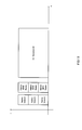
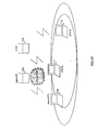
- This wireless LAN system employs such a configuration as shown in Fig.41.
- an access point 100 of 11g controls both of a station 101 of 11g and a station 102 of 11b.
- the station 101 of 11g it becomes possible for the station 101 of 11g to perform a high-speed transmission by transmitting a data frame in the OFDM (Orthogonal Frequency Division Multiplexing) modulation scheme, but the station 102 of 11b recognizes the OFDM signals as interfering signals from other systems because the OFDM signals are not the signals of 11b. Then, depending on a signal level, there may be a case where the station 102 of 11b transmits a data frame in the CCK (Complementary Code Keying) modulation scheme. In such a case, a collision of packets occurs and the throughput is deteriorated.
- OFDM Orthogonal Frequency Division Multiplexing
- the station 101 of 11g transmits a CTS (Clear To Send: a signal to notify the completion of reception) in the DSSS (Direct Sequence Spread Spectrum) modulation scheme, which can be demodulated by the station 102 of 11b and a station, which is not shown, in compliance with the IEEE802.11 (hereinafter, referredto simply as "11"). Due to this, an NAV (Network Allocation Vector: suppression of transmission by a virtual carrier sense) is set to the station 102 of 11b and the station of 11, which is not shown, thereby a collision is avoided.
- CTS Call To Send: a signal to notify the completion of reception
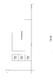
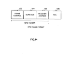
- the frame format of CTS employs a configuration shown in Fig.44. That is, the frame format consists of a frame control section 103, a duration section 104, and a receiver address 105 as an MAC (Media Access Control) header, and an FCS (Frame Check Sequence) section 106. Other terminals that have received such a CTS refrain from performing transmission by setting an NAV in the interval described in the duration section 104. Due to this, a collision is avoided.
- MAC Media Access Control
- FCS Flash Check Sequence
- the station 101 of 11g demodulates or recognize the signal transmitted from the station 102 of 11b, therefore, a collision can be avoided.
- the station 101 of 11g demodulates (or recognizes) the data frame (CCK) transmitted from the station 102 of 11b and sets a backoff to avoid a collision, then transmits an OFDM signal.
- CCK data frame
- a series of procedure shown in Fig.46 is referred to as an "HT sequence”.
- the downward arrow in the diagram shows the transmission and reception of a signal from HTAP to HTSTA and the upward arrow shows the transmission and reception of a signal from HTSTA to HTAP.
- "HT ACK” shows a signal for confirming the completion of reception to the "HT control frame” or "HT DATA frame”.
- the present invention has been developed and an object thereof is to provide a high-speed wireless LAN system capable of avoiding a collision of packets and maintaining the original transmission speed.
- a transmitter according to the present invention is characterized by: being a transmitter applied to a second radio communication system using a second frequency band wider than a first frequency band used in a first communication system; and comprising: an occupation signal generation section for generating an occupation signal compatible with the first radio communication system and notifying the first radio communication system that the second radio communication system occupies a radio medium; and a transmission section for performing communication in the second radio communication system after transmitting the occupation signal using every frequency in the second frequency band.
- the occupation signal since the occupation signal has compatibility with the first radio communication system, it is possible to make the first radio communication system recognize the occupation signal and notify the first radio communication system of the occupation by the second radio communication system. Further, since communication is performed in the second radio communication system after the occupation signal is transmitted using every frequency in the second frequency band, it is possible to perform communication in the second radio communication system while making the first radio communication system suppress transmission and occupying the radio medium. Due to this, a collision of packets can be avoided and the deterioration of throughput can be prevented. As a result, it becomes possible to perform communication at the original transmission speed in the second radio communication system.
- the transmitter according to the present invention is characterized in that the occupation signal generation section adds information for specifying the period during which the second radio communication system occupies the radio medium perfectly to the occupation signal and the transmission section performs communication in the second radio communication system by occupying the radio medium during the period.
- the period during which the second radio communication system occupies the radio medium perfectly is specified, it is possible to prevent the first radio communication system from transmitting information during the period. Due to this, a collision of packets can be avoided and the deterioration of throughput can be prevented. As a result, it becomes possible to perform communication at the original transmission speed in the second radio communication system.
- the transmitter according to the present invention is characterized in that the occupation signal generation section adds information that the second radio communication system occupies a part of the period of the radio medium to the occupation signal and the transmission section performs communication in the second radio communication system by occupying the radio medium during the part of the period based on the information.
- the occupation of the radio medium during the part of the period makes it possible to reserve another part of the period during which the first radio communication system performs communication. Therefore, in the period during which the second radio communication system occupies the radio medium, transmission is suppressed in the first radio communication system and a collision of packets can be avoided and the deterioration of throughput in the second radio communication system can be prevented. On the other hand, in the period during which the second radio communication system does not occupy the radio medium, the first radio communication system can perform communication, therefore, it becomes possible for the first and second radio communication systems to coexist.
- the transmitter according to the present invention is characterized in that the second frequency band has a band width n times (n is a natural number) that of the first frequency band.
- the band width of the frequency used in the second radio communication system is n times (n is a natural number) that of the first frequency band, therefore, it becomes possible to increase the transmission speed compared to that in the first radio communication system.
- the transmitter according to the present invention is characterized in that the occupation signal generation section comprises a symbol repeating section for repeatedly outputting transmission data corresponding to an occupation signal n times (n is a natural number) in predetermined symbol units.
- the transmission data corresponding to the occupation signal is repeatedly outputted n times (n is a natural number) in the predetermined symbol units, it becomes possible to transmit a signal composed of the occupation signals stacked along the frequency axis by converting the output signals from a frequency signal to a time signal.
- the frequency band having the band width n times that of the frequency band used in the first radio communication system is used in the second radio communication system, it is possible to transmit the occupation signal at every frequency in the frequency band used in the second radio communication system by repeating the occupation signal having compatibility with the first radio communication system n times. Due to this, it becomes possible to make the first radio communication system recognize without fail that the radio medium is occupied and suppress transmission without fail. As a result, a collision of packets can be avoided and the deterioration of throughput can be prevented, and it becomes possible to perform communication at the original transmission speed in the second radio communication system.
- the transmitter according to the present invention is characterized in that the occupation signal generation section transmits the occupation signal intermittently.
- the occupation signal is transmitted intermittently, when the occupation signal is transmitted, the radio medium is occupied in the second radio communication system, the transmission is suppressed in the first radio communication system, therefore, a collision of packets can be avoided and the deterioration of the throughput in the second radio communication system can be prevented.
- the occupation signal is not transmitted, since the radio medium is not occupied in the second radio communication system, communication is made possible in the first radio communication system. Due to this, it becomes possible for the first and second radio communication systems to coexist.
- the wording "to transmit intermittently" used here means to or not to transmit the occupation signal at predetermined intervals. For example, it is assumed that a notification signal is transmitted three times during a predetermined time period. In this case, the first and second notification signals are transmitted together with the occupation signal and the last notification signal is transmitted without the occupation signal. It may also be possible not to transmit the occupation signal for the first notification signal and transmit the occupation signal twice for the last two notification signals.
- the transmitter according to the present invention is characterized in that the transmission section transmits at least, out of a start signal for notifying that the period during which communication is performed in the second radio communication system starts and an end signal for notifying that the period during which communication is performed in the second radio communication system ends, the start signal.
- the start signal since at least the start signal is transmitted, it is possible for a receiver in the second radio communication system to clearly grasp the fact that the period during which communication is performed starts. Moreover, by transmitting the end signal, it becomes possible for the receiver in the second radio communication system to clearly grasp the fact that the period during which communication is performed ends without measuring the elapsed time from the start of the period. Since the receiving side clearly grasps the start and end of the above-mentioned period, it becomes possible to easily configure a system in which the occupation period during which the second radio communication system occupies a part of the period of the radio medium is changed, and as a result it becomes possible for the first and second radio communication systems to coexist.
- the transmitter according to the present invention is characterized in that the occupation signal generation section adds identification information that the second radio communication system recognizes the occupation signal to the occupation signal.
- the receiver in the second radio communication system since identification information is added to the occupation signal in order that the second radio communication system can recognize the occupation signal, it is possible for the receiver in the second radio communication system to recognize that the occupation signal is transmitted to the first radio communication system in order to notify that the radio medium is occupied. Due to this, it is possible for the receiver in the second radio communication system to judge whether the data transmitted after the occupation signal is transmitted to the second radio communication system. When the result of judgment is that the data transmitted after the occupation signal is transmitted to the second radio communication system, the data it demodulated, and when the data transmitted after the occupation signal is not transmitted to the second radio communication system, the receiving operation is stopped. Due to this, unnecessary operations are not performed and saving power consumption is made possible.
- the transmitter according to the present invention is characterized in that the occupation signal generation section comprises at least one frequency conversion section for converting the center frequency of an input signal into a predetermined frequency and outputting a frequency-converted signal and an addition section for adding up the input signal and the signal outputted from the frequency conversion section.
- the center frequency of an input signal is converted into a predetermined frequency and added to the input signal, it is possible to generate radio signals arranged in plural when viewed in the direction of the frequency. Due to this, it becomes possible to respectively notify that the second radio communication system occupies each frequency band used by the first radio communication system.
- the receiver according to the present invention is characterizedby: being a receiver applied to the second radio communication system using the second frequency band wider than the first frequency band used in the first radio communication system; and comprising a thinning circuit for cutting out and outputting one n-th of the occupation signal received from the transmitter according to claim 3 and a demodulation section for demodulating the signal inputted from the thinning circuit and outputting the received data.
- the receiver according to the present invention is characterizedby: being a receiver applied to the second radio communication system using the second frequency band wider than the first frequency band used in the first radio communication system; and comprising a start judgment section for judging the start of the period during which the second radio communication system occupies the radio medium based on the start signal received from the transmitter according to claim 7, a measurement section for measuring the elapsed time from the start of the period, an end judgment section for judging the end of the period based on the elapsed time from the start of the period and the start signal, and a control section for outputting a signal for notifying the result of the judgment of the start and end of the period.
- the receiving side since the start of the period during which the second radio communication system occupies the radio medium is recognized based on the start signal, the elapsed time from the start of the period is measured, and the end of the period is recognized based on the elapsed time from the start of the period and the notification signal transmitted at predetermined intervals in the second radio communication system, it becomes possible for the receiving side to grasp without fail the period during which the second radio communication system occupies the radio medium. Since the receiving side clearly grasps the start and end of the above-mentioned period, it becomes possible to easily configure a system in which the occupation period during which the second radio communication system occupies a part of the period of the radio medium is changed, and as a result, it becomes possible for the first and second radio communication systems to coexist.
- the receiver according to the present invention is characterizedby: being a receiver applied to the second radio communication system using the second frequency band wider than the first frequency band used in the first radio communication system; and comprising a start judgment section for judging the start of the period during which the second radio communication system occupies the radio medium based on the start signal received from the transmitter according to claim 7, an end judgment section for judging the end of the period based on the end signal received from the transmitter according to claim 7, and a control section for outputting a signal for notifying the result of judgment of the start and end of the period.
- the receiving side grasp without fail the start and end of the period during which the second radio communication system occupies the radio medium based on the start signal and the end signal. Since the receiving side clearly grasps the start and end of the above-mentioned period, it becomes possible to easily configure a system in which the occupation period during which the second radio communication system occupies a part of the period of the radio medium is changed, and as a result, it becomes possible for the first and second radio communication systems to coexist.
- the receiver according to the present invention is characterizedby: being a receiver applied to the second radio communication system using the second frequency band wider than the first frequency band used in the first radio communication system; and comprising a recognition section for recognizing the identification information based on the occupation signal received from the transmitter according to claim 8 and a reception section for demodulating the received signal and outputting the received data when the identification information is recognized or stopping the receiving operation when the identification information is not recognized.
- the identification information since the identification information is recognized, it is possible to judge whether the data transmitted after the occupation signal is transmitted to the second radio communication system. In other words, when the identification information is recognized, it is possible to judge that the signal transmitted after the occupation signal is transmitted to the second radio communication system, therefore, the signal is demodulated. On the other hand, when the identification information is not recognized, it is possible to judge that the signal data transmitted after the occupation signal is transmitted not to the second radio communication system, therefore, the receiving operation is stopped. Due to this, unnecessary operations are not performed and saving power consumption is made possible.
- the access point according to the present invention is characterized by comprising any one of the transmitters described above.
- the station according to the present invention is characterized by comprising at least one of the receivers described above.
- the wireless LAN system according to the present invention is characterized by comprising the above-mentioned access point and the above-mentioned station.
- the occupation signal since the occupation signal has the compatibility with the first radio communication system, it is possible to make the first radio communication system recognize the occupation signal and notify the occupation by the second radio communication system. Moreover, since communication is performed in the second radio communication system after the occupation signal is transmitted using every frequency in the second frequency band, it is possible to perform communication in the second radio communication system while making the first radio communication system suppress transmission and occupying the radio medium. Due to this, a collision of packets can be avoided and the deterioration of throughput can be prevented. As a result, it becomes possible to perform communication at the original transmission speed in the second radio communication system.
- an HT terminal uses a frequency band n times (n is a natural number) that of a legacy terminal.
- n is a natural number
- the HT terminal uses a frequency band the band width of which is three times that of the legacy terminal. Due to this, a high-speed transmission can be realized between HT terminals.
- An HTAP has the compatibility with a legacy terminal at every frequency (the entire band) at which communication is performed with an HTSTA and transmits an occupation signal for notifying the occupation of the radio medium in a form (for example, CTS) that the legacy terminal can demodulate. Due to this, the HTAP logically occupies the time for performing an HT sequence with respect to the legacy terminal.
- the notification signal means a beacon
- the occupation signal means a CTS.
- Fig.1 a block diagram showing a configuration of a transmitter of an HTSTA applied to a wireless LAN system according to a first embodiment
- Fig.2 is a block diagram showing a configuration of a transmitter of a legacy STA applied to a legacywireless LAN system.
- a transmitter 1 of the HTSTA transmission data are inputted in an MAC circuit 2 and a transmitting/receiving method of a frame, which is a transmission/reception unit of data, a frame format, etc., are defined.
- An Forward Error Correction Coder 3 performs error correction coding for a signal inputted from the MAC circuit 2.
- a modulator 4 performs modulation such as BPSK (Binary PSK) or QPSK (Quadrature PSK) for a signal inputted from the Forward Error Correction Coder 3.
- An IFFT circuit 5 converts a signal inputted from the modulator 4 from a frequency signal into a time signal.
- a filter circuit 6 allows only the signals in a desired band among signals inputted from the IFFT circuit 5 to pass for output and the output signals are transmitted through an antenna 7.
- the Forward Error Correction Coder 3, the modulator 4, the IFFT circuit 5, and the filter circuit 6 compose a transmitting circuit 1a.
- an MAC circuit 11 an Forward Error Correction Coder 12, a modulator 13, an IFFT circuit 14, a filter circuit 15, and an antenna 16 function substantially in the same manner as those in the transmitter 1 of the HTSTA.
- the Forward Error Correction Coder 12, the modulator 13, the IFFT circuit 14, and the filter circuit 15 compose a transmitting circuit 10a.
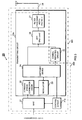
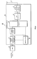
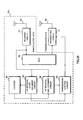
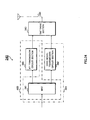
- Fig.3 is a block diagram showing a configuration of a transmitter of an HTAP applied to the wireless LAN system according to the first embodiment.
- an MAC circuit 21 is controlled by a control circuit 21a to define a transmitting/receiving method of a frame, a frame format, etc., for transmission data.
- An Forward Error Correction Coder 22 performs error correction coding for a signal inputted from the MAC circuit 21.
- a modulator 23 performs modulation such as BPSK (Binary PSK) or QPSK (Quadrature PSK) for a signal inputted from the Forward Error Correction Coder 22.
- a switching device 24 is controlled by the control circuit 21a to switch a signal inputted from the modulator 23 to a symbol repeating circuit 25 or an IFFT circuit 26 for output.
- the symbol repeating circuit 25 repeatedly outputs transmission signal data corresponding to an occupation signal generated in the MAC circuit 21, to which error correction coding and modulation processing have been performed, n times (n is a natural number) inpredeterminedsymbol units. Specifically, the symbol is repeated n times for the signal inputted from the switching device 24 and the signal is outputted to the IFFT circuit 26.
- the IFFT circuit 26 converts a signal inputted from the switching device 24 or the symbol repeating circuit 25 from a frequency signal into a time signal.
- a filter circuit 27 allows only the signals in a desired band among the output signals of the IFFT circuit 26 for output and the output signals are transmitted through an antenna 28.
- the Forward Error Correction Coder 22, the modulator 23, the switching device 24, the symbol repeating circuit 25, the IFFT circuit 26, and the filter 27 compose a transmitting circuit 20a.
- the transmitter 20 of this HTAP can transmit an HT signal using a band width n times that of the legacy terminal as shown in Fig.5.
- a part consisting of the transmitting circuit 20a excluding the symbol repeating circuit 25, the MAC circuit 21, and the control circuit 21a is defined as a transmission section 300.
- a part consisting of the transmitting circuit 20a including the symbol repeating circuit 25, the MAC circuit 21, and the control circuit 21a is defined as an occupation signal generation section 301.
- a signal compatible with a legacy terminal is transmitted by directing transmission of a legacy signal from the control circuit 21a included in the occupation signal generation section 301 and outputting transmission signal data from the MAC circuit 21 to the transmitting circuit 20a
- a signal compatible with an HT terminal is transmitted by directing transmission of an HT signal from the control circuit 21a included in the transmission section 300 and outputting transmission signal data from the MAC circuit 21 to the transmitting circuit 20a.
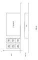
- Fig.7 is a block diagram showing a configuration of a receiver of the HTSTA applied to the wireless LAN system according to the first embodiment.
- the receiver is applied to a wireless LAN system including HT beacons in an HT sequence.
- only the HT signals need to be demodulated.
- a radio signal received by an antenna 31 undergoes a process in which only the signals in a desired band are allowed to pass by a filter circuit 32.
- the output signal of the filter circuit 32 is converted from a time signal into a frequency signal by an FFT circuit 33.
- a demodulator 34 converts a signal inputted from the FFT circuit 33 into a bit string based on the signal point.
- An Forward Error Correction Decoder 35 performs error correction decoding for a signal inputted from the demodulator 34.
- An MAC circuit 36 reads out the transmitting/receiving method of a frame, the frame format, etc. , and outputs the received data.
- the filter circuit 32, the FFT circuit 33, the demodulator 34, and the Forward Error Correction Decoder 35 compose a receiving circuit 30a.
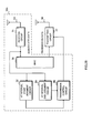
- a receiver of the HTSTA applied to the wireless LAN system employs such a configuration as shown in Fig.8. That is, in a receiver 40, a radio signal received by an antennal 41 undergoes a process in which only the signals in a desired band are allowed to pass by a filter circuit 42. The output signal of the filter circuit 42 is converted from a time signal into a frequency signal by an FFT circuit 43. A switching device 44 switches the output signal of the FFT circuit 43 to a thinning circuit 45 or a demodulator 46 for output.
- the demodulator 46 converts the signal inputted from the switching device 44 or the signal inputted from the thinning circuit 45 intoabit string based on the signal point.
- An Forward Error Correction Decoder 47 performs error correction decoding for the signal inputted from the demodulator 46.
- An MAC circuit 48 reads out the frame transmission/reception method, the frame format, etc., based on the signal inputted from the Forward Error Correction Decoder 47 and outputs the received data.
- the filter circuit 42, the FFT circuit 43, the switching device 44, the thinning circuit 45, the demodulator 46, and the Forward Error Correction Decoder 47 compose a receiving circuit 40a.
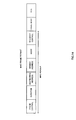
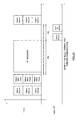
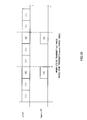
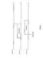
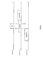
- Fig.10 shows how an HTAP suppresses transmission for a legacy AP.
- the HTAP transmits a legacy beacon, a legacy CTS, and an HT sequence (HT beacon, HT data) in this order. Due to this, it is possible to set an NAV for the legacy AP and the HT sequence can be prevented from a collision of packets. Moreover, it also becomes possible to notify the legacy AP of the presence of another AP in the frequency currently used by transmitting the legacy beacon.
- the legacy beacon and the legacy CTS mean a beacon of 11a format and a CTS of 11a format.
- they mean a beacon of 11 format and a CTS of 11 format.
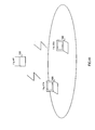
- an HTAP 110 simply transmits a CTS immediately before transmitting HT data and occupies the interval for transmitting the HT data.
- this method it is expected that, for example, transmission of a signal from a legacy STA 114 is started after the transmission of the HT data is completed and the signal and a CTS transmitted by the HTAP 110 collide with each other.
- the radio medium all the time in every band.
- this method it is possible to avoid a collision of packets between the HT terminal and the legacy terminal.
- the possibility is eliminated that the legacy terminal performs transmission during the period of transmission of packets by the HTAP and, by transmitting a signal notifying that the HTAP occupies the radio medium, it is unlikely that the signal from the legacy terminal exists before the HT sequence.
- it is difficult for the HT terminal to demodulate (or recognize) the signal transmitted by the legacy terminal therefore, the fact that no transmission signal from the legacy terminal exists before the HT sequence is really essential in order to avoid a collision.
- the legacy CTS transmitted by the HTAP shown in Fig. 10 may be a legacy CF-poll as shown in Fig. 12.
- the legacy CTS transmitted by the HTAP may be a normal MAC frame that specifies the period to protect in the duration as shown in Fig. 13.
- An MAC frame format in this case is shown in Fig. 14.
- the type and subtype included in the frame control have to be those other than the PS-Poll. This is because in the case of the PS-Poll, the duration interval indicates the AID rather than the duration (refer to IEEE 802.11-1999 7.1.3.1.2 Table - Valid type/subtype combinations).
- HT beacons may be included in an HT sequence.
- the HT terminal has an advantage of being not required to demodulate the legacy information such as the legacy beacon or the legacy CTS.
- HT beacons may not be included in an HT sequence.
- the parameter about the HT transmission namely information about the band width to be used etc. is transmitted/received in the legacy beacon.
- the legacy beacon and the legacy CTS are transmitted as an occupation signal before the HT sequence, it is possible to make the legacy terminal recognize these signals and notify that the HT terminal occupies the radio medium.
- transmission is performed by the HT terminal after the occupation signal is transmitted using every frequency in the frequency band n times that of the legacy terminal, it is possible to perform transmission by the HT terminal while making the legacy terminal suppress transmission and occupying the radio medium. Due to this, a collision of packets can be avoided and the deterioration of throughput can be prevented. As a result, it becomes possible to exhibit the original transmission speed between HT terminals.
- a signal for notifying that the radio medium is occupied is transmitted and the period of time during which an HT sequence is performed is occupied logically with respect to a legacy terminal.
- a legacy AP and an HTAP coexist in the same frequency band
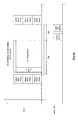
- transmission of both the legacy beacon and the legacy CTS prior to the HT sequence leads to an increase in overhead. Therefore, in the second embodiment, the legacy beacon is not transmitted but the legacy CTS and the HT sequence (HT beacon, HT data) are transmitted in this order, as shown in Fig. 18.
- the legacy CF-poll may be used instead of the legacy CTS.
- the normal MAC frame that specifies the period to protect in the duration maybeused.
- the type and subtype included in the frame control have to be those other than the PS-Poll (refer to IEEE 802.11 - 1999 7.1.3.1.2 Table 1 - Valid type/subtype combinations).
- the HT beacons have to be included in the HT sequence.
- a wireless LAN system In a wireless LAN system according to a third embodiment, coexistence of the HT terminal and the legacy terminal is realized.
- the HT terminal occupies a part of period of the radio medium but does not occupy another part, thereby the coexistence with the legacy terminal is realized.
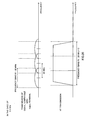
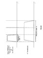
- the time of duration in a legacy MAC frame transmitted by the HT terminal is set to x% (x% is equal to or less than 100%) of the interval from the end of the legacy MAC frame to the next beacon. It is possible to adjust the ratio of communication time of the HT terminal to that of the legacy terminal in accordance with this ratio (the ratio of the part of the radio medium occupied by the HT terminal to the whole).
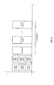
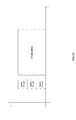
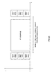
- Fig.22 shows a state in which the HT terminal occupies 100% of the interval from the end of the legacy MAC frame to the next beacon.
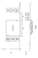
- Fig. 23 shows a state in which the HT terminal occupies, for example, 70% of the interval from the end of the legacy MAC frame to the next beacon and the legacy terminal occupies the rest, that is, 30% thereof.
- the ratio (x%) may be a fixed value or variable.
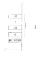
- Fig.24 and Fig.25 it may also possible to transmit the legacy MAC frame and the HT sequence (HT beacon, HT data) in this order without transmitting the legacy beacon and set the time of the duration in the legacy MAC frame to x% (x% is equal to or less than 100%) of the interval from the end of the legacy MAC frame to the next legacy MAC frame.
- an HTSTA it is necessary for an HTSTA to know an HT sequence interval in which HT transmission is possible, therefore, a method for notifying the interval of the HT sequence from an HTAP to the HTSTA is described below.
- an HT beacon in which information about the HT sequence interval is described is included in the HT sequence.
- an HT beacon in which information about the HT sequence interval is described may be included in the HT sequence and an HT interval end signal may be included at the rear of the HT sequence. Due to this, it becomes possible for the HTSTA that receives the HT beacon to grasp the interval during which HT transmission is possible.
- the HTSTA employs such a configuration as shown in Fig.28.
- a radio signal received by an antenna 50 is demodulated in a receiving circuit 51.
- An HT interval start judgment circuit 52 judges the start of the HT interval based on the HT beacon included in the demodulated data outputted from the receiving circuit 51.
- a counter circuit 53 starts a counter based on the output signal of the HT interval start judgment circuit 52. This counter counts the time elapsed from the start of the HT interval.
- An HT interval end judgment circuit 54 judges the end of the HT interval together with the output of the counter circuit 53 according to information about the HT interval included in the HT beacon.
- a transmission control circuit 55 controls a transmitting circuit 57 based on the output signal of the HT interval start judgment circuit 52 and the output signal of the HT interval end judgment circuit 54.
- An MAC circuit 56 defines the transmission/reception method, the format, etc., of a frame that is a transmission/reception unit of data for transmission data and reads out the transmission/reception method of the frame, the frame format, etc., from the received data.
- the transmitting circuit 57 undergoes the control of the transmission control circuit 55 and the MAC circuit 56, converts the transmission data into a radio signal, and transmits the signal through an antenna 58.
- receiving circuit 51 is assumed to be the one to adopt the same composition as receiving circuit 40a shown in Figure 8.
- transmitting circuit 57 is assumed to be the one to adopt the same composition as transmission circuit 20a shown in Figure 3.
- antenna 50, receiving circuit 51, HT interval start judgment circuit 52, counter circuit 53, HT interval end judgment circuit 54, transmission control circuit 55, and MAC circuit 56 compose receiver 59a.
- the HTSTA employs such a conf igurat ion as shown in Fig. 29.
- the configuration is the same as that shown in Fig.28, fromwhich the counter circuit 53 is removed.
- the HT interval start judgment circuit 52 judges the start of the HT interval based on the HT beacon included in the demodulated data outputted from the receiving circuit 51.
- the HT interval end judgment circuit 54 judges the end of the HT interval by receiving the HT interval end signal.
- the transmission control circuit 55 controls the transmitting circuit 57 based on the output signal of the HT interval start judgment circuit 52 and the output signal of the HT interval end judgment circuit 54. Due to this, it is possible for the HTSTA to grasp the start of the HT interval by the HT beacon included at the top of the HT sequence, grasp the end of the HT interval by the HT interval end signal included at the rear of the HT sequence, and know the interval during which HT transmission is possible.
- antenna 50, receiving circuit 51, HT interval start judgment circuit 52, HT interval end judgment circuit 54, transmission control circuit 55, and MAC circuit 56 compose receiver 59b.
- the wireless LAN system in the third embodiment it becomes possible to reserve a period during which the legacy terminal performs transmission by changing the occupation period during which the radio medium is occupied. Therefore, while the HT terminal occupies 100% of the radio medium, the transmission by the legacy terminal is suppressed, a collision of packets is avoided, and the deterioration of throughput is prevented. On the other hand, while the HT terminal does not occupy the radio medium, since the legacy terminal can perform transmission, the coexistence of the HT terminal and the legacy terminal becomes possible. Moreover, since the HT beacon describing information about the HT sequence interval is included in the HT sequence, it is possible for the HTSTA to clearly grasp the start of the period during which transmission is performed.
- the HTAP transmits the HT interval end signal
- the HTSTA since the HTAP transmits the HT interval end signal, it becomes possible for the HTSTA to clearly grasp the end of the period during which transmission is performed without measuring the elapsed time from the start of the period. Since the start and end of the above-mentioned period can be clearly grasped by the receiving side, it becomes possible to easily configure a system in which the occupation period during which the HTAP and HTSTA occupy a part of the period of the radio medium is changed.
- an occupation signal for the occupation of the radio medium is transmitted intermittently in order to realize the coexistence of the HT terminal and the legacy terminal.
- the wording "to transmit intermittently" means to transmit or not to transmit an occupation signal at fixed time intervals.
- L is a natural number
- the legacy MAC frame is transmitted only m times (m is a natural number, equal to or less than L) and not transmitted otherwise.
- P is a natural number
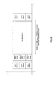
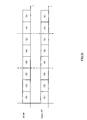
- the HTAP transmits the legacy MAC frame to occupy the radio medium as shown in Fig.31, if it is assumed that x% of the interval (4) is occupied, it is possible for the legacy terminal to perform transmission in the rest of, that is, (100 - x%) of the interval (4) in the interval (5) .
- the HTAP since the HTAP does not transmit the legacy MAC frame nor occupy the radio medium in the interval (2), it becomes possible for the legacy terminal to perform transmission in the interval (3).
- the occupation signal such as the legacy MAC frame is transmitted intermittently. Therefore, when the occupation signal is transmitted, the HT terminal occupies the radio medium, transmission is suppressed at the legacy terminal and a collision of packets is avoided, and the deterioration of throughput is prevented at the HT terminal.
- the occupation signal is not transmitted, since the HT terminal does not occupy the radio medium, it becomes possible for the legacy terminal to perform transmission. Due to this, it becomes possible for the HT terminal and the legacy terminal to coexist.
- the communication time reserved by the HT terminal is adjusted, and the coexistence is realized.
- the number of times the HT sequence occupies x% of the interval from the end of the legacy MAC frame to the next legacy beacon is set to m times (m is a natural number, equal to or less than L) out of L times (L is a natural number) of transmission of the legacy beacon.
- a method for switching the HT sequences in the two kinds of ratios (x% and y% of the interval from the end of the legacy MAC frame to the next beacon) during the L-time transmission of the legacy beacon, but the number of kinds of ratios is not limited to two but i kinds (i is a positive integer, equal to 2 or greater) of ratios are acceptable. Moreover, as shown in Fig.24 and Fig.25, it is also possible to adjust the interval from the end of the legacy MAC frame to the next legacy MAC frame in the above-mentioned ratios.
- the ratio of the communication time between the HT terminal and the legacy terminal is adjusted and it becomes possible to realize the coexistence of both.
- the method is shown, in which the HTAP transmits the legacy CTS to set the NAV for the legacy terminal and suppress transmission, thereby the transmission time of the HT sequence is logically reserved.
- the HTSTA can receive the legacy CTS, it is necessary for the HTSTA to be capable of recognizing that the purpose of the legacy CTS is to reserve the time for the HT sequence.
- the HTAP notifies the HTSTA that the occupation of the medium by CTS is for the occupation for the HT sequence by setting the receiver address included in the legacy CTS transmitted in order to reserve the HT sequence to a specific value.
- the receiver address constitutes identification information.
- the HTSTA may employ such a configuration as shown in Fig.7 or Fig.8.
- the HTSTA employs a configuration including the MAC circuit 36 or 48 as a recognition section for recognizing the receiver address, and the receiving circuit 30a or 40a as a reception section for demodulating a received signal and outputting the received data when the receiver address is recognized as a specific address, or stopping demodulation of the received signal when the receiver address is not recognized as the specific address.
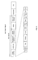
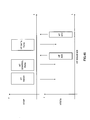
- Fig.32 is a diagram showing a CTS frame format.
- the CTS frame consists of a frame control section 60 as an MAC header, a duration section 61, a receiver address 62, and an FCS section 63.
- the receiver address 62 is a specific address
- the HTSTA since there exists an address that is not used normally in the MAC address, it is possible to make the HTSTA recognize that the received CTS is for the occupation by the HT terminal by using the address.
- step S1 the MAC circuit 36 or 48 judges whether the receiver address included in the legacy CTS is a specific address (step S2). When the result is that the address is a specific address, it is judged that the legacy CTS is from the HTAP and preparation is started for demodulating the HT signal (step S3). Then, the HT signal is demodulated and when the HT interval ends (step S4), the procedure returns to step S1, in which the legacy CTS is waited for to be received again.
- step S5 if the receiver address included in the legacy CTS is not a specific address in step S2 , it is judged that the CTS is from the legacy terminal and the receiving circuit 30a or 40a is stopped (step S5). Then, after the interval of the NAV set by the CTS elapses, the receiving circuit 30a or 40a is activated (step S6) , the procedure returns to step S1, in which the legacy CTS is waited for to be received again.
- the legacy CTS at the HT terminal uses a specific value for the receiver address as identification information for recognizing to be a signal for occupying the radio medium, it is possible for the HT terminal (STA) to recognize that the CTS is transmitted in order to notify the legacy terminal of the occupation of the radio medium. Due to this, it is possible for the HTSTA to judge whether the data transmitted after the CTS is transmitted to the HTSTA. When the judgment result is that the data transmitted after the CTS is transmitted to the HTSTA, the data is demodulated, or when the result is that the data transmitted after the CTS is not transmitted to the HTSTA, the receiving operation is stopped. Due to this, unnecessary operations are not performed and saving power consumption becomes possible.
- the wireless LAN system when a chance for transmission is given to the legacy terminal, it is not easy to perfectly avoid a collision of the HT signal and the legacy signal if the legacy terminal transmits a very long packet. However, when the packet that the legacy terminal transmits is short, it is possible to considerably reduce the possibility of the collision.
- the use in a 5 GHz band is assumed as a specific example. That is, it is assumed that the legacy terminal uses the IEEE802.11a scheme (OFDM scheme). In contrast to this, in a seventh embodiment, a transmitter and a receiver of the HT terminal are explained on the assumption of the use in a 2.4 GHz band, that is, the legacy terminal uses the IEEE802.11 scheme (DSSS scheme).
- OFDM scheme IEEE802.11a scheme
- DSSS scheme IEEE802.11 scheme
- Fig.34 is a block diagram showing a general configuration of a transmitter of an HT terminal used in a 2.4 GHz band.
- transmission data are inputted to an MAC circuit 341 and the MAC circuit 341 outputs transmission signal data to a DSSS signal transmitting circuit section 342 when transmitting a signal compatible with the legacy terminal, and a radio signal is transmitted through a switching section 343 and an antenna 344.
- the MAC circuit 341 when communication is performed with another HT terminal using a frequency band wider than that of the legacy terminal, the MAC circuit 341 outputs the transmission signal data to an HT transmitting circuit section 345 and a radio signal is transmitted through the switching section 343 and the antenna 344.
- HT transmitting circuit section 345 shown in Fig.34 employs the same configuration as that of the transmitting circuit 20a shown in Fig.3.
- the part constituted of the HT transmitting circuit section 345 and the MAC circuit 341 is defined as a transmission section 400.
- the part constituted of the DSSS signal transmitting circuit section 342 and the MAC circuit 341 is defined as an occupation signal generation section 401.
- a signal compatible with the legacy terminal is transmitted by outputting transmission signal data from the MAC circuit 341 to the DSSS signal transmitting circuit 342 included in the occupation signal generation section 401, and a signal compatible with the HT terminal is transmitted by outputting transmission signal data from the MAC circuit 341 to the HT transmitting circuit 345 included in the transmission section 400.
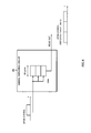
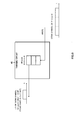
- Fig. 35 is a block diagram showing a detailed configuration of the DSSS signal transmitting circuit section 342 in Fig.34.
- the transmission signal data outputted from the MAC circuit 341 shown in Fig.34 undergoes a scramble process (put into a random state by a specific pattern) in a scramble processing section 351 shown in Fig.35 and then the data is modulation-processed into binary data in a DQPSK / DBPSK modulation section 352.
- the band is limited to 22 MHz in a filter section 354.
- the data outputted from the filter section 354 is inputted to an adder 355, a first frequency conversion section 356a, and a second frequency conversion section 356b, respectively.
- the first frequency conversion section 356a outputs the data the center frequency of which has been shifted by 20 MHz to the adder 355 and the second frequency conversion section 356b outputs the data the center frequency of which has been shifted by 40 MHz to the adder 355.
- the adder 355 adds up the data inputted from the filter section 354, the data inputted from the first frequency conversion section 356a, and the data inputted from the second frequency conversion section 356b. Due to this, a radio signal can be generated, in which three DSSS signals are arranged at 20 MHz intervals when viewed in the direction of frequency.
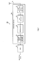
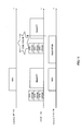
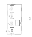
- Fig. 36 is a block diagram showing a general configuration of a receiver of an HT terminal used in a 2.4 GHz band.
- a radio signal is received by an antenna 361 and when the signal is compatible with the legacy terminal, a switching section 362 outputs the signal to a DSSS signal reception circuit section 363 in which the DSSS signal is demodulated, and then the demodulated signal data is outputted to an MAC circuit 364.
- the signal is demodulated by an HT reception circuit section 365 and the demodulated signal data is outputted to the MAC circuit 364.
- the HT reception circuit section 365 employs the same configuration as that of the receiving circuit 40a shown in Fig.8.
- Fig. 37 is a block diagram showing a detailed configuration of the DSSS signal reception circuit section 363 in Fig.36. From among the radio signals outputted from the antenna 361 shown in Fig.36, only the signals in the 22 MHz band required by a filter section 371 shown in Fig. 37 are extracted and an inverse spreading process is performed for the signals by applying a spread code 372a by an inverse spread section 372. The output from the inverse spread section 372 is demodulated into binary data by a delay wave detection section 373 and undergoes a descramble process (the random state by the specific pattern on the transmitting side is released) in a descramble processing section 374, and the obtained reception signal data are outputted to the MAC circuit 364 shown in Fig.36.
- a descramble process the random state by the specific pattern on the transmitting side is released
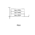
- Fig.38 and Fig.39 are identical to each other in that the occupation signal is a "signal compatible with the legacy terminal in the use of every frequency in a frequency band fh used by the HT terminal.”
Applications Claiming Priority (2)
| Application Number | Priority Date | Filing Date | Title |
|---|---|---|---|
| JP2004136102 | 2004-04-30 | ||
| JP2004136102 | 2004-04-30 |
Publications (4)
| Publication Number | Publication Date |
|---|---|
| EP1592178A2 true EP1592178A2 (fr) | 2005-11-02 |
| EP1592178A3 EP1592178A3 (fr) | 2006-07-05 |
| EP1592178B1 EP1592178B1 (fr) | 2011-07-27 |
| EP1592178B8 EP1592178B8 (fr) | 2012-10-24 |
Family
ID=34941073
Family Applications (1)
| Application Number | Title | Priority Date | Filing Date |
|---|---|---|---|
| EP05252636A Active EP1592178B8 (fr) | 2004-04-30 | 2005-04-27 | Interopérabilité entre différents systèmes de réseaux locaux sans fil |
Country Status (3)
| Country | Link |
|---|---|
| US (1) | US7561510B2 (fr) |
| EP (1) | EP1592178B8 (fr) |
| JP (1) | JP5073036B2 (fr) |
Cited By (2)
| Publication number | Priority date | Publication date | Assignee | Title |
|---|---|---|---|---|
| WO2014179474A1 (fr) * | 2013-05-03 | 2014-11-06 | Qualcomm Incorporated | Réservation de canal dans une communication multiplexée en fréquence dans des environnements sans fil denses |
| EP3066883A1 (fr) * | 2013-11-08 | 2016-09-14 | Qualcomm Incorporated | Systèmes et procédés pour protéger des communications à faible débit dans des réseaux sans fil à haut rendement |
Families Citing this family (25)
| Publication number | Priority date | Publication date | Assignee | Title |
|---|---|---|---|---|
| JP5148275B2 (ja) * | 2004-08-12 | 2013-02-20 | インターデイジタル テクノロジー コーポレーション | 無線通信媒体へのアクセスを制御するための方法およびシステム |
| TWI339540B (en) * | 2005-06-09 | 2011-03-21 | Samsung Electronics Co Ltd | Method and apparatus for transmitting data with down compatibility in high throughput wireless network |
| KR100679041B1 (ko) | 2005-11-30 | 2007-02-05 | 삼성전자주식회사 | 고속 무선 네트워크에서 하향 호환성을 제공하며 데이터를 송수신하는 방법 및 장치 |
| US7944897B2 (en) * | 2005-11-03 | 2011-05-17 | Samsung Electronics Co., Ltd. | Method and system for addressing channel access unfairness in IEEE 802.11n wireless networks |
| KR100782844B1 (ko) | 2006-01-12 | 2007-12-06 | 삼성전자주식회사 | 무선랜에서 채널 본딩을 이용하여 데이터 프레임을전송하는 방법 및 장치 |
| TWI333342B (en) * | 2006-11-06 | 2010-11-11 | Inst Information Industry | Signal relay apparatus, method, application program, and computer readable medium capable of adjusting amplifying gain dynamicaaly |
| JP4450054B2 (ja) * | 2007-11-14 | 2010-04-14 | ソニー株式会社 | 送信装置、受信装置、通信システム、送信方法及びプログラム |
| US8670395B2 (en) * | 2008-06-26 | 2014-03-11 | Samsung Electronics Co., Ltd. | System and method for priority driven contention scheme for supporting enhanced QoS in a wireless communication network |
| US8824495B2 (en) * | 2008-07-02 | 2014-09-02 | Samsung Electronics Co., Ltd. | System and method for reservation of disjoint time intervals in wireless local area networks |
| US20100046488A1 (en) * | 2008-08-20 | 2010-02-25 | Qualcomm Incorporated | Systems and methods for providing a scheduled legacy protection frame |
| JP5159539B2 (ja) * | 2008-09-26 | 2013-03-06 | キヤノン株式会社 | 通信装置、通信装置の制御方法、プログラム。 |
| JP2010093489A (ja) * | 2008-10-07 | 2010-04-22 | Toshiba Corp | 無線通信装置及び無線通信方法 |
| EP2561625B1 (fr) | 2010-04-19 | 2021-12-15 | Samsung Electronics Co., Ltd. | Procédé et système pour opportunité de transmission multiutilisateur pour réseaux sans fil à entrée multiple sortie multiple multiutilisateur |
| US8953578B2 (en) | 2010-06-23 | 2015-02-10 | Samsung Electronics Co., Ltd. | Method and system for contention avoidance in multi-user multiple-input-multiple-output wireless networks |
| US9232543B2 (en) | 2010-07-07 | 2016-01-05 | Samsung Electronics Co., Ltd. | Method and system for communication in multi-user multiple-input-multiple-output wireless networks |
| US9998571B2 (en) * | 2010-10-01 | 2018-06-12 | Qualcomm Incorporated | Legacy-compatible control frames |
| US8917743B2 (en) | 2010-10-06 | 2014-12-23 | Samsung Electronics Co., Ltd. | Method and system for enhanced contention avoidance in multi-user multiple-input-multiple-output wireless networks |
| US9232502B2 (en) | 2012-10-31 | 2016-01-05 | Samsung Electronics Co., Ltd. | Method and system for uplink multi-user multiple-input-multiple-output communication in wireless networks |
| US9419752B2 (en) | 2013-03-15 | 2016-08-16 | Samsung Electronics Co., Ltd. | Transmission opportunity operation of uplink multi-user multiple-input-multiple-output communication in wireless networks |
| US9295074B2 (en) | 2013-09-10 | 2016-03-22 | Samsung Electronics Co., Ltd. | Acknowledgement, error recovery and backoff operation of uplink multi-user multiple-input-multiple-output communication in wireless networks |
| US10834754B2 (en) | 2013-10-29 | 2020-11-10 | Qualcomm Incorporated | Systems and methods for improved communication efficiency in high efficiency wireless networks |
| US9661634B2 (en) | 2013-11-01 | 2017-05-23 | Qualcomm Incorporated | Systems and methods for improved communication efficiency in high efficiency wireless networks |
| JP6406767B2 (ja) * | 2014-01-27 | 2018-10-17 | ホアウェイ・テクノロジーズ・カンパニー・リミテッド | チャネルコンテンション方法、アクセスポイント、及びステーション |
| WO2015190698A1 (fr) * | 2014-06-09 | 2015-12-17 | 엘지전자 주식회사 | Procédé et dispositif de réception de trame |
| US20160119922A1 (en) * | 2014-10-22 | 2016-04-28 | Htc Corporation | Device and Method of Handling Resource Availability of Unlicensed Band |
Citations (1)
| Publication number | Priority date | Publication date | Assignee | Title |
|---|---|---|---|---|
| US20020181426A1 (en) | 2001-03-02 | 2002-12-05 | Sherman Matthew J. | Interference suppression methods for 802.11 |
Family Cites Families (7)
| Publication number | Priority date | Publication date | Assignee | Title |
|---|---|---|---|---|
| US6711122B1 (en) * | 1999-02-08 | 2004-03-23 | Radiolan, Inc. | Frequency offset differential pulse position modulation |
| AU783921B2 (en) * | 2000-11-16 | 2005-12-22 | Symbol Technologies, Inc. | Coexistence techniques in wireless networks |
| JP3530141B2 (ja) * | 2001-03-06 | 2004-05-24 | 松下電器産業株式会社 | 無線lanシステム及び無線lanシステムの信号衝突回避方法 |
| US6977944B2 (en) * | 2002-01-12 | 2005-12-20 | Conexant, Inc. | Transmission protection for communications networks having stations operating with different modulation formats |
| US7010298B2 (en) * | 2002-05-24 | 2006-03-07 | Chrysalis California L.L.C. | Method and apparatus for detecting the presence of a wireless network |
| JP4112397B2 (ja) | 2003-02-14 | 2008-07-02 | 日本電信電話株式会社 | マルチキャリア無線通信システムおよびマルチキャリア変調回路 |
| JP4266192B2 (ja) * | 2004-03-05 | 2009-05-20 | 株式会社東芝 | 無線通信装置及び無線通信方法 |
-
2005
- 2005-04-27 EP EP05252636A patent/EP1592178B8/fr active Active
- 2005-04-28 US US11/116,282 patent/US7561510B2/en active Active
-
2010
- 2010-10-06 JP JP2010226765A patent/JP5073036B2/ja active Active
Patent Citations (1)
| Publication number | Priority date | Publication date | Assignee | Title |
|---|---|---|---|---|
| US20020181426A1 (en) | 2001-03-02 | 2002-12-05 | Sherman Matthew J. | Interference suppression methods for 802.11 |
Cited By (14)
| Publication number | Priority date | Publication date | Assignee | Title |
|---|---|---|---|---|
| US9608796B2 (en) | 2013-05-03 | 2017-03-28 | Qualcomm Incorporated | Methods and systems for frequency multiplexed communication in dense wireless environments |
| RU2632190C2 (ru) * | 2013-05-03 | 2017-10-04 | Квэлкомм Инкорпорейтед | Способы и системы для связи с частотным мультиплексированием в плотных беспроводных средах |
| WO2014179486A1 (fr) * | 2013-05-03 | 2014-11-06 | Qualcomm Incorporated | Attribution d'ensembles de canaux dans une communication à multiplexage en fréquence dans des environnements sans fil denses |
| CN105164940A (zh) * | 2013-05-03 | 2015-12-16 | 高通股份有限公司 | 密集无线环境中的频分复用通信中的信道集分配 |
| EP3454479A1 (fr) * | 2013-05-03 | 2019-03-13 | Qualcomm Incorporated | Mécanisme d'accusé de réception dans des communications à multiplexage de fréquence dans des environnements sans fil denses |
| US9577811B2 (en) | 2013-05-03 | 2017-02-21 | Qualcomm Incorporated | Methods and systems for frequency multiplexed communication in dense wireless environments |
| WO2014179478A1 (fr) * | 2013-05-03 | 2014-11-06 | Qualcomm Incorporated | Mécanisme d'accusé de réception dans une communication à multiplexage en fréquence dans des environnements sans fil denses |
| WO2014179474A1 (fr) * | 2013-05-03 | 2014-11-06 | Qualcomm Incorporated | Réservation de canal dans une communication multiplexée en fréquence dans des environnements sans fil denses |
| RU2658639C2 (ru) * | 2013-05-03 | 2018-06-22 | Квэлкомм Инкорпорейтед | Способы и системы для связи с частотным мультиплексированием в плотных беспроводных окружениях |
| US9843382B2 (en) | 2013-05-03 | 2017-12-12 | Qualcomm Incorporated | Methods and systems for frequency multiplexed communication in dense wireless environments |
| US9680626B2 (en) | 2013-05-03 | 2017-06-13 | Qualcomm Incorporated | Methods and systems for frequency multiplexed communication in dense wireless environments |
| CN105164940B (zh) * | 2013-05-03 | 2019-01-15 | 高通股份有限公司 | 用于信道集分配的方法、装置和介质 |
| US10200115B2 (en) | 2013-05-03 | 2019-02-05 | Qualcomm Incorporated | Methods and systems for frequency multiplexed communication in dense wireless environments |
| EP3066883A1 (fr) * | 2013-11-08 | 2016-09-14 | Qualcomm Incorporated | Systèmes et procédés pour protéger des communications à faible débit dans des réseaux sans fil à haut rendement |
Also Published As
| Publication number | Publication date |
|---|---|
| EP1592178A3 (fr) | 2006-07-05 |
| US20050243843A1 (en) | 2005-11-03 |
| JP5073036B2 (ja) | 2012-11-14 |
| JP2011015443A (ja) | 2011-01-20 |
| US7561510B2 (en) | 2009-07-14 |
| EP1592178B1 (fr) | 2011-07-27 |
| EP1592178B8 (fr) | 2012-10-24 |
Similar Documents
| Publication | Publication Date | Title |
|---|---|---|
| EP1592178B1 (fr) | Interopérabilité entre différents systèmes de réseaux locaux sans fil | |
| US11564264B2 (en) | Medium protection in wireless local area networks | |
| US10602546B2 (en) | Method and apparatus for transmitting frame in wireless LAN | |
| RU2335090C2 (ru) | Способ и устройство для установления, передачи и приема данных для контроля виртуальной несущей при связи в беспроводной сети | |
| US7974225B2 (en) | Providing extended range modes as part of the 802.11n standard | |
| US11368946B2 (en) | Channelization of vehicle-to-everything (V2X) networks | |
| EP1881647A1 (fr) | Dispositif de controle de terminal et systeme lan sans fil | |
| CA2622994A1 (fr) | Procede et appareil permettant de proteger les stations a haut debit | |
| JP2008118692A (ja) | 無線通信システム、無線通信装置及び無線通信方法、並びにコンピュータ・プログラム | |
| MX2007015583A (es) | Metodo y aparato para recibir datos con compatibilidad en una red inalambrica de capacidad elevada. | |
| US10742464B2 (en) | Method and system for multi-protocol transmissions | |
| US10004109B2 (en) | Method and apparatus for recovering data unit in wireless communication system | |
| CN112840614B (zh) | 用于在无线lan系统中配置针对宽频带发送的ngv帧的方法和装置 | |
| JP4861637B2 (ja) | 無線lanシステム | |
| WO2022035741A1 (fr) | Négociation de largeur de bande améliorée | |
| JP4567514B2 (ja) | 通信機、アクセスポイントおよび無線lanシステム | |
| JP2005341532A (ja) | 無線lanシステム | |
| WO2023075921A1 (fr) | Planification coordonnée et signalisation de périodes de service de temps de sillage cible restreint (r-twt) | |
| WO2022260942A1 (fr) | Diffusion de balises d'identifiants d'ensemble de services de base (bssid) multiples | |
| JP4086788B2 (ja) | 無線通信システム | |
| JP6901082B2 (ja) | 無線通信装置および無線通信方法 | |
| WO2023201147A1 (fr) | Synchronisation temporelle sur un réseau sans fil pour trafic sensible à la latence | |
| EP4353018A1 (fr) | Diffusion de balises d'identifiants d'ensemble de services de base (bssid) multiples | |
| WO2023044207A1 (fr) | Sélection de candidat d'itinérance avec détection d'ensemble de services de base (obss) se chevauchant |
Legal Events
| Date | Code | Title | Description |
|---|---|---|---|
| PUAI | Public reference made under article 153(3) epc to a published international application that has entered the european phase |
Free format text: ORIGINAL CODE: 0009012 |
|
| AK | Designated contracting states |
Kind code of ref document: A2 Designated state(s): AT BE BG CH CY CZ DE DK EE ES FI FR GB GR HU IE IS IT LI LT LU MC NL PL PT RO SE SI SK TR |
|
| AX | Request for extension of the european patent |
Extension state: AL BA HR LV MK YU |
|
| PUAL | Search report despatched |
Free format text: ORIGINAL CODE: 0009013 |
|
| AK | Designated contracting states |
Kind code of ref document: A3 Designated state(s): AT BE BG CH CY CZ DE DK EE ES FI FR GB GR HU IE IS IT LI LT LU MC NL PL PT RO SE SI SK TR |
|
| AX | Request for extension of the european patent |
Extension state: AL BA HR LV MK YU |
|
| 17P | Request for examination filed |
Effective date: 20061016 |
|
| 17Q | First examination report despatched |
Effective date: 20061122 |
|
| AKX | Designation fees paid |
Designated state(s): DE FR GB |
|
| RIC1 | Information provided on ipc code assigned before grant |
Ipc: H04W 16/14 20090101AFI20101013BHEP Ipc: H04W 74/04 20090101ALN20101013BHEP Ipc: H04W 84/12 20090101ALN20101013BHEP |
|
| GRAP | Despatch of communication of intention to grant a patent |
Free format text: ORIGINAL CODE: EPIDOSNIGR1 |
|
| GRAS | Grant fee paid |
Free format text: ORIGINAL CODE: EPIDOSNIGR3 |
|
| GRAA | (expected) grant |
Free format text: ORIGINAL CODE: 0009210 |
|
| AK | Designated contracting states |
Kind code of ref document: B1 Designated state(s): DE FR GB |
|
| REG | Reference to a national code |
Ref country code: GB Ref legal event code: FG4D |
|
| REG | Reference to a national code |
Ref country code: DE Ref legal event code: R096 Ref document number: 602005029170 Country of ref document: DE Effective date: 20110922 |
|
| PLBE | No opposition filed within time limit |
Free format text: ORIGINAL CODE: 0009261 |
|
| 26N | No opposition filed |
Effective date: 20120502 |
|
| PLAA | Information modified related to event that no opposition was filed |
Free format text: ORIGINAL CODE: 0009299DELT |
|
| PLBE | No opposition filed within time limit |
Free format text: ORIGINAL CODE: 0009261 |
|
| STAA | Information on the status of an ep patent application or granted ep patent |
Free format text: STATUS: NO OPPOSITION FILED WITHIN TIME LIMIT |
|
| REG | Reference to a national code |
Ref country code: DE Ref legal event code: R097 Ref document number: 602005029170 Country of ref document: DE Effective date: 20120502 |
|
| R26N | No opposition filed (corrected) |
Effective date: 20120502 |
|
| RIN2 | Information on inventor provided after grant (corrected) |
Inventor name: NAKASHIMA, DAIICHIRO Inventor name: IMAMURA, KIMIHIKO |
|
| REG | Reference to a national code |
Ref country code: FR Ref legal event code: PLFP Year of fee payment: 12 |
|
| REG | Reference to a national code |
Ref country code: FR Ref legal event code: PLFP Year of fee payment: 13 |
|
| REG | Reference to a national code |
Ref country code: FR Ref legal event code: PLFP Year of fee payment: 14 |
|
| PGFP | Annual fee paid to national office [announced via postgrant information from national office to epo] |
Ref country code: FR Payment date: 20230420 Year of fee payment: 19 Ref country code: DE Payment date: 20230420 Year of fee payment: 19 |
|
| PGFP | Annual fee paid to national office [announced via postgrant information from national office to epo] |
Ref country code: GB Payment date: 20230419 Year of fee payment: 19 |