EP1591995A1 - Indoor communication system for a vehicular cabin - Google Patents
Indoor communication system for a vehicular cabin Download PDFInfo
- Publication number
- EP1591995A1 EP1591995A1 EP04010231A EP04010231A EP1591995A1 EP 1591995 A1 EP1591995 A1 EP 1591995A1 EP 04010231 A EP04010231 A EP 04010231A EP 04010231 A EP04010231 A EP 04010231A EP 1591995 A1 EP1591995 A1 EP 1591995A1
- Authority
- EP
- European Patent Office
- Prior art keywords
- test signal
- communication system
- indoor communication
- transfer function
- signal
- Prior art date
- Legal status (The legal status is an assumption and is not a legal conclusion. Google has not performed a legal analysis and makes no representation as to the accuracy of the status listed.)
- Granted
Links
Images


Classifications
-
- H—ELECTRICITY
- H03—ELECTRONIC CIRCUITRY
- H03G—CONTROL OF AMPLIFICATION
- H03G5/00—Tone control or bandwidth control in amplifiers
- H03G5/16—Automatic control
- H03G5/165—Equalizers; Volume or gain control in limited frequency bands
-
- H—ELECTRICITY
- H04—ELECTRIC COMMUNICATION TECHNIQUE
- H04R—LOUDSPEAKERS, MICROPHONES, GRAMOPHONE PICK-UPS OR LIKE ACOUSTIC ELECTROMECHANICAL TRANSDUCERS; ELECTRIC HEARING AIDS; PUBLIC ADDRESS SYSTEMS
- H04R29/00—Monitoring arrangements; Testing arrangements
- H04R29/001—Monitoring arrangements; Testing arrangements for loudspeakers
-
- H—ELECTRICITY
- H04—ELECTRIC COMMUNICATION TECHNIQUE
- H04R—LOUDSPEAKERS, MICROPHONES, GRAMOPHONE PICK-UPS OR LIKE ACOUSTIC ELECTROMECHANICAL TRANSDUCERS; ELECTRIC HEARING AIDS; PUBLIC ADDRESS SYSTEMS
- H04R3/00—Circuits for transducers
- H04R3/02—Circuits for transducers for preventing acoustic reaction, i.e. acoustic oscillatory feedback
-
- H—ELECTRICITY
- H04—ELECTRIC COMMUNICATION TECHNIQUE
- H04R—LOUDSPEAKERS, MICROPHONES, GRAMOPHONE PICK-UPS OR LIKE ACOUSTIC ELECTROMECHANICAL TRANSDUCERS; ELECTRIC HEARING AIDS; PUBLIC ADDRESS SYSTEMS
- H04R2499/00—Aspects covered by H04R or H04S not otherwise provided for in their subgroups
- H04R2499/10—General applications
- H04R2499/13—Acoustic transducers and sound field adaptation in vehicles
-
- H—ELECTRICITY
- H04—ELECTRIC COMMUNICATION TECHNIQUE
- H04R—LOUDSPEAKERS, MICROPHONES, GRAMOPHONE PICK-UPS OR LIKE ACOUSTIC ELECTROMECHANICAL TRANSDUCERS; ELECTRIC HEARING AIDS; PUBLIC ADDRESS SYSTEMS
- H04R5/00—Stereophonic arrangements
- H04R5/02—Spatial or constructional arrangements of loudspeakers
Definitions
- the invention is directed to an indoor communication system for a vehicular cabin and to a method for automatically determining an equalizing filter characteristic for an indoor communication system of a vehicular cabin.
- a noisy environment can render communication between different persons very difficult or almost impossible, particularly if the noise is at a similar loudness level as the speech.
- a strong background noise is present in a vehicular cabin (such as the passenger compartment of a car) due to engine and wind noise.
- Further possible noise sources that can deteriorate the mutual understanding of the people are the loudspeakers of a car radio or a handsfree telephone system. Due to the multitude of different noise sources, a communication both between the front seat and back seat passengers and between the driver and the front seat passenger, for example, is very difficult, in particular when the vehicle is moving at a high speed.
- an indoor communication system for cars has been proposed to improve communication between people located in a passenger compartment.
- one microphone is associated with each passenger seat, including the driver's seat. This means that in the vicinity of each seat or in the vicinity of a passenger's head sitting on a seat, a microphone is arranged.
- Each microphone records the speech of the respective passenger and the corresponding signals are output via loudspeakers in the car.
- the loudspeakers already present in the car can be associated to the different passenger seats. For example, if a loudspeaker is mounted in each door, the respective loudspeaker can be associated to the person sitting next to it. This allows for outputting the speech signals mainly at loudspeakers corresponding to passengers other than the current speaker. For example, if the driver is speaking, the corresponding speech signal may be output at the different loudspeakers except the for the driver's loudspeaker(s).
- This object is solved by a method for automatically determining an equalizing filter characteristic for an indoor communication system of a vehicular cabin according to claims 1 and 2 and by an indoor communication system for a vehicular cabin according to claim 14 and 15.
- the invention provides a method for automatically determining an equalizing filter characteristic for an indoor communication system of a vehicular cabin, the indoor communication system comprising at least one microphone and at least one loudspeaker, comprising the steps of:
- the invention also provides a method for automatically determining an equalizing filter characteristic for an indoor communication system of a vehicular cabin, the indoor communication system comprising at least one loudspeaker and at least one microphone array connected to a beamformer, comprising the steps of:
- microphone (if not explicitly used in the context of microphone arrays) is used to denote a single microphone or, in other words, a microphone not being part of a microphone array.
- a loudspeaker may comprise several components such as a high-frequency and a low-frequency unit.
- a transfer function is a function characterizing the transmission properties of a transmission path. These transmission properties can result from the geometry of the room where the test signal is transmitted from one or several loudspeakers to one or several microphones and/or microphone arrays and possible objects located therein. Furthermore, the transmission properties can also be influenced by electronic components along the signal path, e.g., between the signal generator and the loudspeaker.
- the received signal is a function, namely the transfer function, of the original test signal.
- the test signal is a signal as generated by a signal generator.
- a beamformer processes signals emanating from a microphone array to obtain a combined signal.
- beamforming comprises delay compensation and summing of the signals. Beamforming allows providing a specific directivity pattern for a microphone array.
- a test signal is used to determine the transmission properties of the signal path as a function in the frequency domain. Based on these transmission properties, an equalizing filter characteristic is determined.
- this method allows for the detection of possible feedback frequencies via the transfer function that can be used for an appropriate modification of a signal to be output in order to reduce the occurrence of feedback effects.
- the indoor communication system for which this method is used can comprise one or several (single) microphones and/or one or several microphone arrays. Such a microphone or microphone array can be associated to a potential speaker (passenger) and be mounted at appropriate positions. Furthermore, the indoor communication system can also comprise one or several loudspeakers associated with a microphone or microphone array and the corresponding speaker position.
- the predetermined test signal can be emitted by (exactly) one loudspeaker.
- a transfer function is obtained and a corresponding equalizing filter characteristic can be determined such that for each pair, an appropriate equalizing filter is provided.
- the test signal can be received simultaneously by each microphone or microphone array. This allows to determine in parallel an equalizing filter characteristic for each of these microphones or microphone arrays with respect to a given loudspeaker.
- Step a) can comprise emitting binary white noise or colored noise, particularly pink noise.
- white noise all frequencies (in the present context, usually, only frequencies within the range of human hearing are considered) are present and uniformly distributed. This enables a comparison of original test signal and received test signal in a very simple way. A more pleasing sound for people being present in the vehicular cabin is obtained using colored noise, particularly pink noise. Pink noise can be obtained by filtering white noise to reduce the volume at each octave.
- Step c) can comprise processing the test signal and the received test signal in the time domain, in particular, using an adaptive filter or using an estimation method based on a periodogram, an autocorrelation function or cross-correlation function.
- Processing in the time domain is particularly useful when using broadband test signals.
- an NLMS (normalized least means squared) algorithm as described, e.g., in S. Haykin, B. Widrow, Least-Mean-Square Adaptive Filtering, John Wiley and Sons, 2003
- the impulse response is to be transformed into the frequency domain so as to obtain the transfer function.
- step a) can comprise emitting band pass noise with variable center frequency. In this case, however, all frequency ranges should be activated.
- step c) can comprise determining the square root of the quotient of the short time power spectrum of the received test signal and the short time power spectrum of the test signal for each band pass noise.
- the transfer function can also be obtained in this way.
- step d) can comprise determining an extremum, in particular, a maximum, of the magnitude of the transfer function.
- a frequency for which the transfer function has a (global or local) maximum is considered as possible feedback frequency.
- Step d) can comprise determining a global extremum of the magnitude of the transfer function.
- the global maximum with respect to the overall frequency range to be considered has a high probability of constituting a feedback frequency.
- Step d) can further comprise determining a local extremum for which the magnitude of the transfer function differs not more than a predetermined amount from the magnitude of the transfer function at a global extremum. Particularly in the case of local maxima, other frequencies (in addition to the global maximum) are also considered as possible feedback frequencies.
- Step d) can further comprise providing an attenuation of a predetermined frequency band of a signal being centered at a determined maximum and/or providing an amplification of a predetermined frequency band being centered at a determined minimum.
- the (broadband) stability limit can be improved by the value corresponding to the applied attenuation. Particularly if a small attenuation bandwidth is chosen, the acoustic impression of an audio signal in the vehicular cabin will hardly differ.
- the attenuating step can be performed using a nonlinear phase filter. This has the advantage that inserting small delay time differences when reproducing mono signals can improve the subjective quality impression of the signal.
- the invention also provides a method for automatically determining a maximum amplification value of an indoor communication system of a vehicular cabin, comprising the steps of:
- the invention provides a computer program product comprising one or more computer readable media having computer-executable instructions for performing the steps of the above-described methods.
- the invention provides an indoor communication system for a vehicular cabin, comprising:
- an indoor communication system for a vehicular cabin comprising:
- each microphone array is connected to the signal processing means via a beamformer. It is to be understood that microphones and microphone arrays can both be used in a vehicular cabin. For example, microphone arrays can be provided for the front passengers whereas for back passengers, only single microphones are present.
- the indoor communication system can comprise at least two loudspeakers and the signal generator can be connected to the at least two loudspeakers in such a way that the test signal can be separately emitted by each loudspeaker. This allows to separately perform the previously described methods for each loudspeaker independently of the other loudspeakers.
- the signal generator can be configured to emit binary white noise or colored noise, particularly pink noise.
- the signal processing means of the indoor communication system can be configured to process the test signal and the received test signal in the time domain, in particular, using an adaptive filter or using an estimation method based on a periodogram, an autocorrelation function or a cross-correlation function.
- the signal processing means can comprise an NLMS (normalized least means squared) adaptive filter.
- the signal generator can be configured to emit band pass noise with variable center frequency.
- the signal processing means can be configured to determine the square root of the quotient of the short time power spectrum of the received test signal and the short time power spectrum of the test signal for each band pass noise.
- the signal processing means of the previously described indoor communication systems can be configured to automatically determine an extremum, in particular, a maximum of the magnitude of the transfer function.
- the signal processing means can be configured to determine a global extremum of the magnitude of the transfer function.
- the signal processing means can be configured to further determine a local extremum for which the magnitude of the transfer function differs not more than a predetermined amount from the magnitude of the transfer function and a global extremum.
- the signal processing means can be configured to automatically attenuate a predetermined frequency band being centered at a determined maximum and/or to amplify a predetermined frequency band being centered at a determined minimum.
- the signal processing means can comprise a nonlinear phase filter for attenuating a predetermined frequency band.
- the vehicular cabin 100 comprises four passengers' seats (not shown) and four passengers 101. With each passenger, a microphone array comprising two microphones 102 and a loudspeaker 103 are associated. For the front passengers, the microphone arrays are arranged in the center between the passengers. They can be provided at the car roof, for example. At the rear seats, the microphone arrays are provided at the left and right side of the passengers, respectively, for example, in the car door.
- Each loudspeaker can comprise a high-frequency and a low-frequency unit, for example.
- the microphone arrays record signals.
- the signals emanating from the microphone arrays enter a digital signal processing means 104 and 104'.
- a first signal processing means 104 is responsible for processing the signals emanating from the microphones associated with the rear passengers and a second digital signal processing means 104' is associated with the signals emanating from the microphones associated with the front passengers.
- the signals emanating from the microphone arrays are processed by an analog/digital converter (not shown). This is followed by a beamformer 105 and 105'.
- the beamformers serve to obtain information on the temporal signal behavior and also spatial information about the signal sources of both wanted (e.g. passengers) and noise signal sources (e.g. car radio loudspeakers). Different types of beamformers (e.g., adaptive beamformers) can be used for the present invention.
- echo and feedback components are subtracted from the signal via adaptive echo cancellation 106 and 106' and feedback cancellation 107 and 107'.
- Adaptive notch filters 108 and 108' can detect potential feedback frequencies and attenuate these.
- Attenuators are controlled such that, for example, only the loudest speaker is switched through.
- a post processing 109 and 109' can apply a boundary characteristic.
- the output signals of the digital signal processing means 104 and 104' are fed, first of all, to corresponding loudspeakers 103.
- signals emanating from rear microphone arrays can only be output by front loudspeakers and vice versa.
- the system can also be configured, for example, such that the processed signals can be output by all loudspeakers except the loudspeakers corresponding to the microphone array of the input signals.
- the processed signals are also fed to feedback cancellation 107 and 107' of the same digital signal processing means and also to echo cancellation means 106 and 106' of the other digital signal processing means.
- directional microphones can be used instead of microphone arrays.
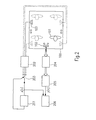
- FIG. 2 An example of an indoor communication system and the method for operating the same is illustrated in Fig. 2. Again, a vehicular cabin 100 and a passenger 101 (and possible other passengers) are shown. In the illustrated example, the method for determining an equalizing filter characteristic is performed for only one active loudspeaker 103; the other loudspeakers that are not active are indicated by dashed lines.
- a signal generator 201 is present for providing a test signal x ( n ). Such a test signal is passed through a D/A converter and amplifier 202. Each loudspeaker can be addressed independently of the other loudspeakers, which is indicated by a switch 203.
- the test signal emitted by loudspeaker 103 is recorded by the microphone arrays 102.
- the test signal can be recorded by all microphone arrays simultaneously; however, it is also possible to successively record the signal by the different microphone arrays.
- the signals emanating from the microphone arrays are passed through an A/D converter and amplifier 204. After that, beamforming is performed in beamformer 205 yielding a beamformed signal y(n). This signal is passed to signal processing means 206 that is not only connected to the microphone array but also to signal generator 201 to receive the test signal x(n).
- the signal processing means 206 that is responsible for determining an equalizing filter characteristic can be part of signal processing means 104 or 104' of Fig. 1. However, it is also possible to provide this signal processing means 206 as a separate unit. This is particularly useful for later equipping a vehicle that already has an indoor communication system mounted therein.
- a test signal is generated.
- different test signals are possible.
- binary white noise can be used as test signal. This is an advantageous choice since all frequencies are present and uniformly distributed.
- colored noise can also be used. For example, pink noise can be generated. As long as all frequencies are sufficiently activated, other colored noises can also be used.
- narrowband test signals such as band pass noise with variable center frequency. In this case, all frequency ranges should be activated successively.
- the test signal is emitted by one of the loudspeakers. This corresponds to the configuration of Fig. 2. However, two or more loudspeakers can alternatively emit the test signal in parallel.
- the test signal is received by a microphone array, particularly by all microphone arrays.
- the signal emanating from the microphone array and having passed through the beamformer is fed to a signal processing means where the test signal and the received test signal are used to automatically determine a transfer function in the frequency domain in step 304.
- the transmission behavior can be determined in the time domain, for example, using an adaptive filter.
- the normalized least mean square (NLMS) algorithm with small increments can be adopted.
- the impulse response is to be transformed to the frequency domain to obtain the transfer function H ( e j ⁇ ).
- adaptive filters one can also use estimation methods based on periodograms or on autocorrelation or cross-correlation functions.
- the transfer function can be determined as the square root of the quotient of the short time power spectra ⁇ 2 y (n)/ ⁇ 2 x (n).
- Both short time power spectra are determined for each band pass noise so as to obtain sampling points at the center frequencies of the band pass signals.
- an equalizing filter characteristic is determined such that an equalizing filter for microphone array/loudspeaker pair is obtained resulting in a reduced feedback risk for this pair of components.
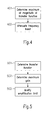
- Fig. 4 illustrates an example of how to determine (at least parts of) an equalizing filter characteristic in step 305 of Fig. 3. This is particularly useful, when determining the transfer function using adaptive filters as described above. According to this example, one or several maxima of the transfer function H ( e j ⁇ ) are determined in step 401, in other words, a maximum frequency ⁇ max
- the number of frequencies determined in this way particularly depends on the design principle of the equalization filters. For example, 3 - 5 frequency values can be determined if these frequencies are sufficiently separated. If this is not the case, one can also determine more than 5 frequency values.
- an attenuation is provided for one or several frequency bands (depending on the number of possible feedback frequencies) in step 402.
- attenuations are applied in small bands around the determined frequencies ⁇ max .
- attenuations of some dB can be inserted whereas the remaining frequency ranges are not attenuated.
- Corresponding steps can be performed for amplifying minima of the transfer function. In such a case, minimum frequencies are to be determined and corresponding amplifications are to be applied. In this way, an output signal is considered louder by the listener.
- Fig. 5 illustrates a modification of the maximum amplification (stability limit) of an indoor communication system after having determined the transfer function in step 501 as described above.
- the maximum gain (amplification) is determined in step 502
- Gain max 1/max ⁇
- this stability limit can be individually determined for each vehicle (and each loudspeaker and microphone or microphone array mounted therein) and can be used to correct (increase) the maximum amplification as originally set by the manufacturer. In this way, the quality of indoor communication systems can further be improved.
- equalizing filters are used for reproducing signals of the indoor communication system, the equalizing filters should be placed before the mixing matrices of the audio amplifiers. In this case, the equalizing filters do not modify the sound of other audio sources of the vehicle.
Landscapes
- Health & Medical Sciences (AREA)
- General Health & Medical Sciences (AREA)
- Otolaryngology (AREA)
- Physics & Mathematics (AREA)
- Engineering & Computer Science (AREA)
- Acoustics & Sound (AREA)
- Signal Processing (AREA)
- Fittings On The Vehicle Exterior For Carrying Loads, And Devices For Holding Or Mounting Articles (AREA)
- Circuit For Audible Band Transducer (AREA)
- Tone Control, Compression And Expansion, Limiting Amplitude (AREA)
Abstract
Description
- The invention is directed to an indoor communication system for a vehicular cabin and to a method for automatically determining an equalizing filter characteristic for an indoor communication system of a vehicular cabin.
- In many different circumstances, a noisy environment can render communication between different persons very difficult or almost impossible, particularly if the noise is at a similar loudness level as the speech. As a particular example, a strong background noise is present in a vehicular cabin (such as the passenger compartment of a car) due to engine and wind noise. Further possible noise sources that can deteriorate the mutual understanding of the people are the loudspeakers of a car radio or a handsfree telephone system. Due to the multitude of different noise sources, a communication both between the front seat and back seat passengers and between the driver and the front seat passenger, for example, is very difficult, in particular when the vehicle is moving at a high speed.
- In the prior art, an indoor communication system for cars has been proposed to improve communication between people located in a passenger compartment. According to this prior art system, one microphone is associated with each passenger seat, including the driver's seat. This means that in the vicinity of each seat or in the vicinity of a passenger's head sitting on a seat, a microphone is arranged. Each microphone records the speech of the respective passenger and the corresponding signals are output via loudspeakers in the car. Usually, the loudspeakers already present in the car can be associated to the different passenger seats. For example, if a loudspeaker is mounted in each door, the respective loudspeaker can be associated to the person sitting next to it. This allows for outputting the speech signals mainly at loudspeakers corresponding to passengers other than the current speaker. For example, if the driver is speaking, the corresponding speech signal may be output at the different loudspeakers except the for the driver's loudspeaker(s).
- These prior art indoor communication systems, however, have the drawback that, particularly at higher amplification levels, undesirable feedback effects may occur. In principle, this drawback could be overcome by setting the stability limit (i.e., the maximal admissible amplification) in a very conservative way by the manufacturer. In other words, the maximal amplification limit can be set to such a value that under almost all circumstances, no undesired feedback effect will occur. This has the consequence, however, that in most cases, an optimal (higher) amplification that might sometimes be necessary will not be achieved.
- In view of this, it is the object of the invention to provide a method for operating an indoor communication system, in particular, a method for automatically determining a possible feedback frequency of an indoor communication system, and an indoor communication system for a vehicular cabin.
- This object is solved by a method for automatically determining an equalizing filter characteristic for an indoor communication system of a vehicular cabin according to claims 1 and 2 and by an indoor communication system for a vehicular cabin according to claim 14 and 15.
- Accordingly, the invention provides a method for automatically determining an equalizing filter characteristic for an indoor communication system of a vehicular cabin, the indoor communication system comprising at least one microphone and at least one loudspeaker, comprising the steps of:
- a) emitting a predetermined test signal by a loudspeaker, in particular, one loudspeaker, of the indoor communication system,
- b) receiving the test signal by a microphone of the indoor communication system to obtain a received test signal,
- c) automatically determining a transfer function in the frequency domain based on the test signal and the received test signal,
- d) automatically determining an equalizing filter characteristic based on the transfer function.
-
- The invention also provides a method for automatically determining an equalizing filter characteristic for an indoor communication system of a vehicular cabin, the indoor communication system comprising at least one loudspeaker and at least one microphone array connected to a beamformer, comprising the steps of:
- a) emitting a predetermined test signal a loudspeaker, in particular, one loudspeaker, of the indoor communication system,
- b) receiving and beamforming the test signal by a microphone array of the indoor communication system and beamforming the signals emanating from the microphone array using the beamformer connected thereto to obtain a received test signal,
- c) automatically determining a transfer function in the frequency domain based on the test signal and the received test signal,
- d) automatically determining an equalizing filter characteristic based on the transfer function.
-
- Here and in the following, the term "microphone" (if not explicitly used in the context of microphone arrays) is used to denote a single microphone or, in other words, a microphone not being part of a microphone array. A loudspeaker may comprise several components such as a high-frequency and a low-frequency unit.
- A transfer function is a function characterizing the transmission properties of a transmission path. These transmission properties can result from the geometry of the room where the test signal is transmitted from one or several loudspeakers to one or several microphones and/or microphone arrays and possible objects located therein. Furthermore, the transmission properties can also be influenced by electronic components along the signal path, e.g., between the signal generator and the loudspeaker. The received signal is a function, namely the transfer function, of the original test signal. The test signal is a signal as generated by a signal generator.
- A beamformer processes signals emanating from a microphone array to obtain a combined signal. In its simplest form (delay-and-sum beamformer), beamforming comprises delay compensation and summing of the signals. Beamforming allows providing a specific directivity pattern for a microphone array.
- Thus, according to the method of the invention, a test signal is used to determine the transmission properties of the signal path as a function in the frequency domain. Based on these transmission properties, an equalizing filter characteristic is determined. Hence, in contrast to prior art indoor communication systems, this method allows for the detection of possible feedback frequencies via the transfer function that can be used for an appropriate modification of a signal to be output in order to reduce the occurrence of feedback effects.
- The indoor communication system for which this method is used can comprise one or several (single) microphones and/or one or several microphone arrays. Such a microphone or microphone array can be associated to a potential speaker (passenger) and be mounted at appropriate positions. Furthermore, the indoor communication system can also comprise one or several loudspeakers associated with a microphone or microphone array and the corresponding speaker position.
- In particular, in step a), the predetermined test signal can be emitted by (exactly) one loudspeaker. In this way, in particular, for each loudspeaker/microphone pair or each loudspeaker/microphone array pair, a transfer function is obtained and a corresponding equalizing filter characteristic can be determined such that for each pair, an appropriate equalizing filter is provided. In step a), the test signal can be received simultaneously by each microphone or microphone array. This allows to determine in parallel an equalizing filter characteristic for each of these microphones or microphone arrays with respect to a given loudspeaker.
- Step a) can comprise emitting binary white noise or colored noise, particularly pink noise. In white noise, all frequencies (in the present context, usually, only frequencies within the range of human hearing are considered) are present and uniformly distributed. This enables a comparison of original test signal and received test signal in a very simple way. A more pleasing sound for people being present in the vehicular cabin is obtained using colored noise, particularly pink noise. Pink noise can be obtained by filtering white noise to reduce the volume at each octave.
- Step c) can comprise processing the test signal and the received test signal in the time domain, in particular, using an adaptive filter or using an estimation method based on a periodogram, an autocorrelation function or cross-correlation function. Processing in the time domain is particularly useful when using broadband test signals. For example, an NLMS (normalized least means squared) algorithm (as described, e.g., in S. Haykin, B. Widrow, Least-Mean-Square Adaptive Filtering, John Wiley and Sons, 2003) can be used After processing in the time domain, the impulse response is to be transformed into the frequency domain so as to obtain the transfer function.
- As an alternative to using broadband test signals, step a) can comprise emitting band pass noise with variable center frequency. In this case, however, all frequency ranges should be activated.
- When emitting band pass noise, step c) can comprise determining the square root of the quotient of the short time power spectrum of the received test signal and the short time power spectrum of the test signal for each band pass noise. The transfer function can also be obtained in this way.
- In the above-described methods, step d) can comprise determining an extremum, in particular, a maximum, of the magnitude of the transfer function. A frequency for which the transfer function has a (global or local) maximum is considered as possible feedback frequency.
- Step d) can comprise determining a global extremum of the magnitude of the transfer function. In particular, the global maximum with respect to the overall frequency range to be considered has a high probability of constituting a feedback frequency.
- Step d) can further comprise determining a local extremum for which the magnitude of the transfer function differs not more than a predetermined amount from the magnitude of the transfer function at a global extremum. Particularly in the case of local maxima, other frequencies (in addition to the global maximum) are also considered as possible feedback frequencies.
- Step d) can further comprise providing an attenuation of a predetermined frequency band of a signal being centered at a determined maximum and/or providing an amplification of a predetermined frequency band being centered at a determined minimum.
- This yields a particularly advantageous equalizing. Due to such an attenuation of a signal to be output by a loudspeaker, the (broadband) stability limit can be improved by the value corresponding to the applied attenuation. Particularly if a small attenuation bandwidth is chosen, the acoustic impression of an audio signal in the vehicular cabin will hardly differ.
- The attenuating step can be performed using a nonlinear phase filter. This has the advantage that inserting small delay time differences when reproducing mono signals can improve the subjective quality impression of the signal.
- The invention also provides a method for automatically determining a maximum amplification value of an indoor communication system of a vehicular cabin, comprising the steps of:
- automatically determining an equalizing filter characteristic using the above-described methods for a predetermined loudspeaker,
- automatically determining the maximum amplification as
-
- Determining this maximum amplification or gain allows increasing the maximum amplification as set by the manufacturer, for example.
- Furthermore, the invention provides a computer program product comprising one or more computer readable media having computer-executable instructions for performing the steps of the above-described methods.
- In addition, the invention provides an indoor communication system for a vehicular cabin, comprising:
- a signal generator configured to generate a predetermined test signal,
- at least one loudspeaker connected to the signal generator for emitting the predetermined test signal,
- at least one microphone for receiving the emitted test signal to provide a received test signal,
- a signal processing means connected to the signal generator and to the at least one microphone wherein the signal processing means is configured to automatically determine a transfer function in the frequency domain based on the test signal and the received signal and to automatically determine an equalizing filter characteristic based on the transfer function.
-
- Furthermore, an indoor communication system for a vehicular cabin is provided, comprising:
- a signal generator configured to generate a predetermined test signal,
- at least one loudspeaker connected to the signal generator for emitting the predetermined test signal,
- at least one microphone array for receiving the emitted test signal,
- a beamformer for each microphone array for beamforming the signals emanating from a microphone array to provide a received test signal,
- a signal processing means connected to the signal generator and to the at least one microphone array, wherein the signal processing means is configured to automatically determine a transfer function in the frequency domain based on the test signal and the received test signal and to automatically determine an equalizing filter characteristic based on the transfer function.
-
- These indoor communication systems allow to use components that are often already present in a vehicular cabin such as loudspeakers and microphone or microphone arrays, for example, for use in a handsfree telephone system. Then, in the case of microphone arrays, each microphone array is connected to the signal processing means via a beamformer. It is to be understood that microphones and microphone arrays can both be used in a vehicular cabin. For example, microphone arrays can be provided for the front passengers whereas for back passengers, only single microphones are present.
- The indoor communication system can comprise at least two loudspeakers and the signal generator can be connected to the at least two loudspeakers in such a way that the test signal can be separately emitted by each loudspeaker. This allows to separately perform the previously described methods for each loudspeaker independently of the other loudspeakers.
- The signal generator can be configured to emit binary white noise or colored noise, particularly pink noise.
- The signal processing means of the indoor communication system can be configured to process the test signal and the received test signal in the time domain, in particular, using an adaptive filter or using an estimation method based on a periodogram, an autocorrelation function or a cross-correlation function. In particular, the signal processing means can comprise an NLMS (normalized least means squared) adaptive filter.
- As an alternative to a signal generator configured to emit broadband noise, the signal generator can be configured to emit band pass noise with variable center frequency.
- In this case, the signal processing means can be configured to determine the square root of the quotient of the short time power spectrum of the received test signal and the short time power spectrum of the test signal for each band pass noise.
- The signal processing means of the previously described indoor communication systems can be configured to automatically determine an extremum, in particular, a maximum of the magnitude of the transfer function.
- The signal processing means can be configured to determine a global extremum of the magnitude of the transfer function.
- Then, the signal processing means can be configured to further determine a local extremum for which the magnitude of the transfer function differs not more than a predetermined amount from the magnitude of the transfer function and a global extremum.
- The signal processing means can be configured to automatically attenuate a predetermined frequency band being centered at a determined maximum and/or to amplify a predetermined frequency band being centered at a determined minimum.
- In such a case, the signal processing means can comprise a nonlinear phase filter for attenuating a predetermined frequency band.
- The signal processing means can also be configured to automatically determine a maximum amplification value as
- Further features and advantages of the invention will be described in the following with respect to the examples and figures in which:
- Fig. 1
- is a schematic illustration of an example of an indoor communication system of a vehicular cabin;
- Fig. 2
- schematically illustrates an example of an indoor communication system allowing determining an equalizing filter characteristic;
- Fig. 3
- is a flow diagram of an example of a method for automatically determining an equalizing filter characteristic;
- Fig. 4
- illustrates an example of how to attenuate a possible feedback frequency; and
- Fig. 5
- is a flow diagram of an example of a method for modifying a maximum amplification.
- Where the present invention is described with reference to the embodiments as illustrated in the following detailed description as well as in the drawings, it should be understood that the detailed description and the drawings are not intended to limit the present invention to the particular illustrative embodiments disclosed, but rather the described illustrated embodiments merely exemplify the various aspects of the present invention, the scope of which is defined by the appended claims.
- An overview of a system for indoor communication in a
vehicular cabin 100 is shown in Fig. 1. Thevehicular cabin 100 comprises four passengers' seats (not shown) and fourpassengers 101. With each passenger, a microphone array comprising twomicrophones 102 and aloudspeaker 103 are associated. For the front passengers, the microphone arrays are arranged in the center between the passengers. They can be provided at the car roof, for example. At the rear seats, the microphone arrays are provided at the left and right side of the passengers, respectively, for example, in the car door. Each loudspeaker can comprise a high-frequency and a low-frequency unit, for example. - The microphone arrays record signals. The signals emanating from the microphone arrays enter a digital signal processing means 104 and 104'. In the example shown in Fig. 1, a first signal processing means 104 is responsible for processing the signals emanating from the microphones associated with the rear passengers and a second digital signal processing means 104' is associated with the signals emanating from the microphones associated with the front passengers. However, this is only a matter of choice and the signals emanating from the different microphone arrays and also the signals output by the different loudspeakers can be processed in different combinations.
- The signals emanating from the microphone arrays, first of all, are processed by an analog/digital converter (not shown). This is followed by a
beamformer 105 and 105'. The beamformers serve to obtain information on the temporal signal behavior and also spatial information about the signal sources of both wanted (e.g. passengers) and noise signal sources (e.g. car radio loudspeakers). Different types of beamformers (e.g., adaptive beamformers) can be used for the present invention. - Independent of the method according to the invention, additional feedback effects can also be avoided during operation of the indoor communication system.
- For this, echo and feedback components are subtracted from the signal via
adaptive echo cancellation 106 and 106' andfeedback cancellation 107 and 107'.Adaptive notch filters 108 and 108' can detect potential feedback frequencies and attenuate these. - Based on the temporal and the spatial information from the beamformer, attenuators are controlled such that, for example, only the loudest speaker is switched through. However such a corresponding component is not shown explicitly in Fig. 1. A
post processing 109 and 109' can apply a boundary characteristic. The output signals of the digital signal processing means 104 and 104' are fed, first of all, to correspondingloudspeakers 103. In the example shown in Fig. 1, signals emanating from rear microphone arrays can only be output by front loudspeakers and vice versa. This is, however, not a necessary restriction, the system can also be configured, for example, such that the processed signals can be output by all loudspeakers except the loudspeakers corresponding to the microphone array of the input signals. - Furthermore, the processed signals are also fed to
feedback cancellation 107 and 107' of the same digital signal processing means and also to echo cancellation means 106 and 106' of the other digital signal processing means. - As an alternative to the example shown in Fig. 1, it is also possible to replace some or all of the microphone arrays by single microphones. For example, directional microphones can be used instead of microphone arrays.
- An example of an indoor communication system and the method for operating the same is illustrated in Fig. 2. Again, a
vehicular cabin 100 and a passenger 101 (and possible other passengers) are shown. In the illustrated example, the method for determining an equalizing filter characteristic is performed for only oneactive loudspeaker 103; the other loudspeakers that are not active are indicated by dashed lines. - A
signal generator 201 is present for providing a test signal x(n). Such a test signal is passed through a D/A converter andamplifier 202. Each loudspeaker can be addressed independently of the other loudspeakers, which is indicated by aswitch 203. - The test signal emitted by
loudspeaker 103 is recorded by themicrophone arrays 102. In particular, the test signal can be recorded by all microphone arrays simultaneously; however, it is also possible to successively record the signal by the different microphone arrays. The signals emanating from the microphone arrays are passed through an A/D converter andamplifier 204. After that, beamforming is performed inbeamformer 205 yielding a beamformed signal y(n). This signal is passed to signal processing means 206 that is not only connected to the microphone array but also to signalgenerator 201 to receive the test signal x(n). - The signal processing means 206 that is responsible for determining an equalizing filter characteristic can be part of signal processing means 104 or 104' of Fig. 1. However, it is also possible to provide this signal processing means 206 as a separate unit. This is particularly useful for later equipping a vehicle that already has an indoor communication system mounted therein.
- The course of action of an example of a method for automatically determining an equalizing filter characteristic is illustrated in Fig. 3. In a
first step 301, a test signal is generated. In principle, different test signals are possible. In particular, binary white noise can be used as test signal. This is an advantageous choice since all frequencies are present and uniformly distributed. However, since, in most cases, passengers are sitting in the vehicular cabin, colored noise can also be used. For example, pink noise can be generated. As long as all frequencies are sufficiently activated, other colored noises can also be used. - Instead of broadband signals, it is also possible to use narrowband test signals such as band pass noise with variable center frequency. In this case, all frequency ranges should be activated successively.
- In the
following step 302, the test signal is emitted by one of the loudspeakers. This corresponds to the configuration of Fig. 2. However, two or more loudspeakers can alternatively emit the test signal in parallel. - Then, in
step 303, the test signal is received by a microphone array, particularly by all microphone arrays. The signal emanating from the microphone array and having passed through the beamformer is fed to a signal processing means where the test signal and the received test signal are used to automatically determine a transfer function in the frequency domain instep 304. In the case of broadband test signals, the transmission behavior can be determined in the time domain, for example, using an adaptive filter. For this, the normalized least mean square (NLMS) algorithm with small increments can be adopted. After that, the impulse response is to be transformed to the frequency domain to obtain the transfer function H(e jΩ ). Instead of adaptive filters, one can also use estimation methods based on periodograms or on autocorrelation or cross-correlation functions. - If narrowband test signals are adopted, the transfer function can be determined as the square root of the quotient of the short time power spectra
- Both short time power spectra are determined for each band pass noise so as to obtain sampling points at the center frequencies of the band pass signals.
- In the
subsequent step 305, an equalizing filter characteristic is determined such that an equalizing filter for microphone array/loudspeaker pair is obtained resulting in a reduced feedback risk for this pair of components. - By performing these steps for a specific loudspeaker and simultaneously for all microphone arrays, equalizing filters are obtained for each of these pairs. Then, the steps are to be repeated with another loudspeaker until the method was performed for all loudspeakers being present in the vehicular cabin.
- Fig. 4 illustrates an example of how to determine (at least parts of) an equalizing filter characteristic in
step 305 of Fig. 3. This is particularly useful, when determining the transfer function using adaptive filters as described above. According to this example, one or several maxima of the transfer function H(e jΩ ) are determined instep 401, in other words, a maximum frequency Ωmax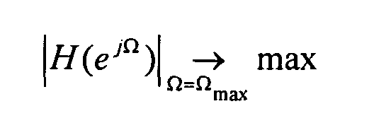
- is determined. The number of frequencies determined in this way, particularly depends on the design principle of the equalization filters. For example, 3 - 5 frequency values can be determined if these frequencies are sufficiently separated. If this is not the case, one can also determine more than 5 frequency values.
- When using narrowband test noise, the frequencies Ωmax or the band pass ranges with the largest quotient are determined based on the above described short time power spectra.
- Then, for a particular loudspeaker/microphone array pair, possible feedback frequencies have been determined.
- After having determined a possible feedback frequency in
step 401, an attenuation is provided for one or several frequency bands (depending on the number of possible feedback frequencies) instep 402. In this step, attenuations are applied in small bands around the determined frequencies Ωmax. In particular, attenuations of some dB can be inserted whereas the remaining frequency ranges are not attenuated. - Corresponding steps can be performed for amplifying minima of the transfer function. In such a case, minimum frequencies are to be determined and corresponding amplifications are to be applied. In this way, an output signal is considered louder by the listener.
- Since the transfer functions of different loudspeaker/microphone array pairs are usually different, an additional positive effect can be achieved when using nonlinear phase equalizing filters. By insertion of small delay differences when playing mono signals via several loudspeakers, the subject quality impression can be increased (see e.g. M. Schroeder, Computer Speech - Recognition, Compression, Synthesis, Springer 1999). This effect can be considered when determining the equalization filters.
- Fig. 5 illustrates a modification of the maximum amplification (stability limit) of an indoor communication system after having determined the transfer function in
step 501 as described above. The maximum gain (amplification) is determined instep 502 - Knowing about this stability limit, the maximum amplification can be modified accordingly in
step 503. This enables to operate the indoor communication system near the stability limit, which is particularly useful in the case of large ambient noise. Due to the determination of the transfer function, this stability limit can be individually determined for each vehicle (and each loudspeaker and microphone or microphone array mounted therein) and can be used to correct (increase) the maximum amplification as originally set by the manufacturer. In this way, the quality of indoor communication systems can further be improved. - Since equalizing filters are used for reproducing signals of the indoor communication system, the equalizing filters should be placed before the mixing matrices of the audio amplifiers. In this case, the equalizing filters do not modify the sound of other audio sources of the vehicle.
- In addition, the previously described methods can also be used to improve the audio output of other audio components such as handsfree systems or speech recognition. If it is detected by the method that the so-called center loudspeaker being located at the vicinity of the front microphones creates larger microphone signals than the other loudspeakers, its output power can be reduced correspondingly. An overdriving of the microphones due to the audio output can be avoided in this way, which increases the performance of the handsfree system or the speech recognition system.
- Further modifications and variations of the present invention will be apparent to those skilled in the art in view of this description. Accordingly, the description is to be construed as illustrative only and is for the purpose of teaching those skilled in the art the general manner of carrying out the present invention. It is to be understood that the forms of the invention as shown and described herein are to be taken as the presently preferred embodiments.
Claims (26)
- Method for automatically determining an equalizing filter characteristic for an indoor communication system of a vehicular cabin, the indoor communication system comprising at least one loudspeaker and at least one microphone, comprising the steps of:a) emitting a predetermined test signal by a loudspeaker, in particular, by one loudspeaker, of the indoor communication system,b) receiving the test signal by a microphone of the indoor communication system to obtain a received test signal,c) automatically determining a transfer function in the frequency domain based on the test signal and the received test signal,d) automatically determining an equalizing filter characteristic based on the transfer function.
- Method for automatically determining an equalizing filter characteristic for an indoor communication system of a vehicular cabin, the indoor communication system comprising at least one loudspeaker and at least one microphone array connected to a beamformer, comprising the steps of:a) emitting a predetermined test signal by a loudspeaker, in particular, by one loudspeaker, of the indoor communication system,b) receiving the test signal by a microphone array of the indoor communication system and beamforming the signals emanating from the microphone array using the beamformer connected thereto to obtain a received test signal,c) automatically determining a transfer function in the frequency domain based on the test signal and the received test signal,d) automatically determining an equalizing filter characteristic based on the transfer function.
- Method according to claim 1 or 2, wherein step a) comprises emitting binary white noise or colored noise, particularly, pink noise.
- Method according to one of the preceding claims, wherein step c) comprises processing the test signal and the received test signal in the time domain, in particular, using an adaptive filter or using an estimation method based on a periodogram, an autocorrelation function or a cross-correlation function.
- Method according to claim 1 or 2, wherein step a) comprises emitting band pass noise with variable center frequency.
- Method according to claim 5, wherein step c) comprises determining the square root of the quotient of the short time power spectrum of the received test signal and the short time power spectrum of the test signal for each band pass noise.
- Method according to one of the preceding claims, wherein step d) comprises determining an extremum, in particular, a maximum, of the magnitude of the transfer function.
- Method according to claim 7, wherein step d) comprises determining a global extremum of the magnitude of the transfer function.
- Method according to claim 8, wherein step d) further comprises determining a local extremum for which the magnitude of the transfer function differs not more than a predetermined amount from the magnitude of the transfer function at a global extremum.
- Method according to one of the claims 7 - 9, wherein step d) further comprises providing an attenuation of a predetermined frequency band being centered at a determined maximum and/or providing an amplification of a predetermined frequency band being centered at a determined minimum.
- Method according to claim 10, wherein an attenuation is provided using a nonlinear phase filter.
- Method for automatically determining a maximum amplification value of an indoor communication system of a vehicular cabin, comprising the steps of:with H(e jΩ ) the transfer function and G(e jΩ ) the frequency response of the equalizing filter.automatically determining an equalizing filter characteristic using the method of one of the claims 1 - 11 for a predetermined loudspeaker,automatically determining the maximum amplification as
- Computer program product, comprising one or more computer readable media having computer-executable instructions for performing the steps of the method of one of the preceding claims.
- Indoor communication system for a vehicular cabin, comprising:a signal generator configured to generate a predetermined test signal,at least one loudspeaker connected to the signal generator for emitting the predetermined test signal,at least one microphone for receiving the emitted test signal to provide a received test signal,a signal processing means connected to the signal generator and to the at least one microphone, wherein the signal processing means is configured to automatically determine a transfer function in the frequency domain based on the test signal and the received test signal and to automatically determine an equalizing filter characteristic based on the transfer function.
- Indoor communication system for a vehicular cabin, comprising
a signal generator configured to generate a predetermined test signal,
at least one loudspeaker connected to the signal generator for emitting a predetermined test signal,
at least one microphone array for receiving the emitted test signal,
a beamformer for each microphone array for beamforming the signals emanating from a microphone array to provide a received test signal,
a signal processing means connected to the signal generator and to the at least one microphone array, wherein the signal processing means is configured to automatically determine a transfer function in the frequency domain based on the test signal and the received test signal and to automatically determine an equalizing filter characteristic based on the transfer function. - Indoor communication system according to claim 14 or 15, comprising at least two loudspeakers and wherein the signal generator is connected to the at least two loudspeakers in such a way that the test signal can be separately emitted by each loudspeaker.
- Indoor communication system according to one of the claims 14 - 16, wherein the signal generator is configured to emit binary white noise or colored noise, particularly, pink noise.
- Indoor communication system according to one of the claims 14 - 17, wherein the signal processing means is configured to process the test signal and the received test signal in the time domain, in particular, using an adaptive filter or using an estimation method based on a periodogram, an autocorrelation function or a cross-correlation function.
- Indoor communication system according to one of the claims 14 - 18, wherein the signal generator is configured to emit band pass noise with variable center frequency.
- Indoor communication system according to claim 19, wherein the signal processing means is configured to determine the square root of the quotient of the short time power spectrum of the received test signal and the short time power spectrum of the test signal for each band pass noise.
- Indoor communication system according to one of the claims 14 - 20, wherein the signal processing means is configured to automatically determine an extremum, in particular, a maximum, of the magnitude of the transfer function
- Indoor communication system according to one of the claims 21, wherein the signal processing means is configured to determine a global extremum of the magnitude of the transfer function.
- Indoor communication system according to claim 23, wherein the signal processing means is configured to further determine a local extremum for which the magnitude of the transfer function differs not more than a predetermined amount from the magnitude of the transfer function at a global extremum.
- Indoor communication system according to one of the claims 14 - 23, wherein the signal processing means is configured to automatically attenuate a predetermined frequency band being centered at a determined maximum and/or to amplify a predetermined frequency band being centered at a determined minimum.
- Indoor communication system according to claim 24, wherein the signal processing means comprises a nonlinear phase filter for attenuating a predetermined frequency band.
- Indoor communication system according to one of the claims 14 - 26, wherein the signal processing means is configured to automatically determine a maximum amplification as
Priority Applications (4)
| Application Number | Priority Date | Filing Date | Title |
|---|---|---|---|
| EP04010231.1A EP1591995B1 (en) | 2004-04-29 | 2004-04-29 | Indoor communication system for a vehicular cabin |
| JP2005133496A JP2005318636A (en) | 2004-04-29 | 2005-04-28 | Indoor communication system for cabin for vehicle |
| US11/118,092 US8081776B2 (en) | 2004-04-29 | 2005-04-29 | Indoor communication system for a vehicular cabin |
| JP2011131638A JP5694063B2 (en) | 2004-04-29 | 2011-06-13 | Indoor communication system for vehicle cabin |
Applications Claiming Priority (1)
| Application Number | Priority Date | Filing Date | Title |
|---|---|---|---|
| EP04010231.1A EP1591995B1 (en) | 2004-04-29 | 2004-04-29 | Indoor communication system for a vehicular cabin |
Publications (2)
| Publication Number | Publication Date |
|---|---|
| EP1591995A1 true EP1591995A1 (en) | 2005-11-02 |
| EP1591995B1 EP1591995B1 (en) | 2019-06-19 |
Family
ID=34924788
Family Applications (1)
| Application Number | Title | Priority Date | Filing Date |
|---|---|---|---|
| EP04010231.1A Expired - Lifetime EP1591995B1 (en) | 2004-04-29 | 2004-04-29 | Indoor communication system for a vehicular cabin |
Country Status (3)
| Country | Link |
|---|---|
| US (1) | US8081776B2 (en) |
| EP (1) | EP1591995B1 (en) |
| JP (2) | JP2005318636A (en) |
Cited By (9)
| Publication number | Priority date | Publication date | Assignee | Title |
|---|---|---|---|---|
| EP1860911A1 (en) * | 2006-05-24 | 2007-11-28 | Harman/Becker Automotive Systems GmbH | System and method for improving communication in a room |
| WO2008122930A1 (en) * | 2007-04-04 | 2008-10-16 | Koninklijke Philips Electronics N.V. | Sound enhancement in closed spaces |
| WO2015187042A1 (en) * | 2014-06-03 | 2015-12-10 | Maziewski Przemyslaw P | Automated equalization of microphones |
| WO2016093974A1 (en) * | 2014-12-12 | 2016-06-16 | Qualcomm Incorporated | Feedback cancelation for enhanced conversational communications in shared acoustic space |
| WO2016093971A1 (en) * | 2014-12-12 | 2016-06-16 | Qualcomm Incorporated | Enhanced auditory experience in shared acoustic space |
| WO2016093973A1 (en) * | 2014-12-12 | 2016-06-16 | Qualcomm Incorporated | Enhanced conversational communications in shared acoustic space |
| EP3364666A1 (en) * | 2017-02-17 | 2018-08-22 | 2236008 Ontario, Inc. | System and method for feedback control for in-car communications |
| EP3370438A1 (en) * | 2017-03-02 | 2018-09-05 | Vestel Elektronik Sanayi ve Ticaret A.S. | Loudspeaker testing and protection |
| EP4723677A1 (en) * | 2024-10-07 | 2026-04-08 | Harman Becker Automotive Systems, Inc. | System for operating in-cabin loudspeakers of a vehicle |
Families Citing this family (40)
| Publication number | Priority date | Publication date | Assignee | Title |
|---|---|---|---|---|
| US20110311065A1 (en) * | 2006-03-14 | 2011-12-22 | Harman International Industries, Incorporated | Extraction of channels from multichannel signals utilizing stimulus |
| EP1858295B1 (en) * | 2006-05-19 | 2013-06-26 | Nuance Communications, Inc. | Equalization in acoustic signal processing |
| US8214219B2 (en) * | 2006-09-15 | 2012-07-03 | Volkswagen Of America, Inc. | Speech communications system for a vehicle and method of operating a speech communications system for a vehicle |
| DE102007014816B4 (en) | 2007-03-28 | 2023-05-17 | Iav Gmbh Ingenieurgesellschaft Auto Und Verkehr | Communication system and method for operating a communication system in a vehicle |
| US8411847B2 (en) * | 2008-06-10 | 2013-04-02 | Conexant Systems, Inc. | Acoustic echo canceller |
| WO2010138309A1 (en) | 2009-05-26 | 2010-12-02 | Dolby Laboratories Licensing Corporation | Audio signal dynamic equalization processing control |
| WO2010138311A1 (en) * | 2009-05-26 | 2010-12-02 | Dolby Laboratories Licensing Corporation | Equalization profiles for dynamic equalization of audio data |
| JP5290949B2 (en) * | 2009-12-17 | 2013-09-18 | キヤノン株式会社 | Sound processing apparatus and method |
| EP2416593A1 (en) * | 2010-08-02 | 2012-02-08 | Svox AG | Method for indoor communication |
| EP2490459B1 (en) | 2011-02-18 | 2018-04-11 | Svox AG | Method for voice signal blending |
| EP2530835B1 (en) * | 2011-05-30 | 2015-07-22 | Harman Becker Automotive Systems GmbH | Automatic adjustment of a speed dependent equalizing control system |
| EP2727378B1 (en) | 2011-07-01 | 2019-10-16 | Dolby Laboratories Licensing Corporation | Audio playback system monitoring |
| US9641934B2 (en) * | 2012-01-10 | 2017-05-02 | Nuance Communications, Inc. | In-car communication system for multiple acoustic zones |
| CN103428607A (en) * | 2012-05-25 | 2013-12-04 | 华为技术有限公司 | Audio signal playing system and electronic device |
| EP2850611B1 (en) * | 2012-06-10 | 2019-08-21 | Nuance Communications, Inc. | Noise dependent signal processing for in-car communication systems with multiple acoustic zones |
| EP2859772B1 (en) | 2012-06-10 | 2018-12-19 | Nuance Communications, Inc. | Wind noise detection for in-car communication systems with multiple acoustic zones |
| US9805738B2 (en) | 2012-09-04 | 2017-10-31 | Nuance Communications, Inc. | Formant dependent speech signal enhancement |
| US8880058B2 (en) * | 2012-09-14 | 2014-11-04 | Toyota Motor Engineering & Manufacturing North America, Inc. | Automatic tuning system |
| US9613633B2 (en) | 2012-10-30 | 2017-04-04 | Nuance Communications, Inc. | Speech enhancement |
| US10194260B2 (en) | 2015-02-27 | 2019-01-29 | Pioneer Corporation | Sound volume control device, sound volume control method and sound volume control program |
| US10091581B2 (en) | 2015-07-30 | 2018-10-02 | Roku, Inc. | Audio preferences for media content players |
| EP3133831A1 (en) * | 2015-08-20 | 2017-02-22 | Harman Becker Automotive Systems GmbH | System and method for in-car communication |
| CN105280195B (en) * | 2015-11-04 | 2018-12-28 | 腾讯科技(深圳)有限公司 | The processing method and processing device of voice signal |
| EP3171613A1 (en) * | 2015-11-20 | 2017-05-24 | Harman Becker Automotive Systems GmbH | Audio enhancement |
| US11348595B2 (en) * | 2017-01-04 | 2022-05-31 | Blackberry Limited | Voice interface and vocal entertainment system |
| JP6873549B2 (en) * | 2017-03-28 | 2021-05-19 | 株式会社ディーアンドエムホールディングス | Audio equipment and computer readable programs |
| US10210882B1 (en) | 2018-06-25 | 2019-02-19 | Biamp Systems, LLC | Microphone array with automated adaptive beam tracking |
| US10433086B1 (en) | 2018-06-25 | 2019-10-01 | Biamp Systems, LLC | Microphone array with automated adaptive beam tracking |
| US10694285B2 (en) | 2018-06-25 | 2020-06-23 | Biamp Systems, LLC | Microphone array with automated adaptive beam tracking |
| ES2983992T3 (en) * | 2018-08-02 | 2024-10-28 | Nippon Telegraph & Telephone | Sound collecting speaker device, method and program for the same |
| FR3087076B1 (en) * | 2018-10-08 | 2022-02-25 | Arkamys | METHOD AND DEVICE FOR CONTROLLING THE DISTORTION OF A SPEAKER SYSTEM EMBEDDED IN A VEHICLE |
| US11211061B2 (en) | 2019-01-07 | 2021-12-28 | 2236008 Ontario Inc. | Voice control in a multi-talker and multimedia environment |
| US10857909B2 (en) | 2019-02-05 | 2020-12-08 | Lear Corporation | Electrical assembly |
| JP7211498B2 (en) * | 2019-05-21 | 2023-01-24 | 日本電信電話株式会社 | SOUND PROCESSING DEVICE, SOUND PROCESSING METHOD, AND PROGRAM |
| JP7286532B2 (en) * | 2019-12-27 | 2023-06-05 | フォルシアクラリオン・エレクトロニクス株式会社 | Signal processing device, sound device, signal processing method and signal processing program |
| KR20220117217A (en) * | 2019-12-30 | 2022-08-23 | 하만 베커 오토모티브 시스템즈 게엠베하 | How to perform acoustic measurements |
| WO2021226628A2 (en) | 2020-05-04 | 2021-11-11 | Shure Acquisition Holdings, Inc. | Intelligent audio system using multiple sensor modalities |
| US11297452B2 (en) * | 2020-08-14 | 2022-04-05 | Subaru Corporation | Inspection system and inspection method |
| US11985488B2 (en) | 2021-05-26 | 2024-05-14 | Shure Acquisition Holdings, Inc. | System and method for automatically tuning digital signal processing configurations for an audio system |
| DE102022002500A1 (en) * | 2022-07-08 | 2024-01-11 | Mercedes-Benz Group AG | Method for directional calibration of microphones arranged on a vehicle |
Citations (3)
| Publication number | Priority date | Publication date | Assignee | Title |
|---|---|---|---|---|
| US4739513A (en) * | 1984-05-31 | 1988-04-19 | Pioneer Electronic Corporation | Method and apparatus for measuring and correcting acoustic characteristic in sound field |
| US5386478A (en) * | 1993-09-07 | 1995-01-31 | Harman International Industries, Inc. | Sound system remote control with acoustic sensor |
| EP0898364A2 (en) * | 1990-12-11 | 1999-02-24 | B & W LOUDSPEAKERS LIMITED | Compensating filters |
Family Cites Families (29)
| Publication number | Priority date | Publication date | Assignee | Title |
|---|---|---|---|---|
| NL8300671A (en) * | 1983-02-23 | 1984-09-17 | Philips Nv | AUTOMATIC EQUALIZATION SYSTEM WITH DTF OR FFT. |
| US5170433A (en) * | 1986-10-07 | 1992-12-08 | Adaptive Control Limited | Active vibration control |
| EP0304257A3 (en) | 1987-08-19 | 1989-09-27 | McGregor, Thomas | Voice enhancer system |
| JP2938076B2 (en) * | 1988-02-23 | 1999-08-23 | 株式会社東芝 | Echo canceller device |
| JP2604510B2 (en) * | 1991-09-26 | 1997-04-30 | 富士通テン株式会社 | Automatic sound frequency characteristic correction device |
| JP2940585B2 (en) * | 1992-11-16 | 1999-08-25 | 株式会社ケンウッド | Transmission frequency characteristic correction device |
| JP3235925B2 (en) * | 1993-11-19 | 2001-12-04 | 松下電器産業株式会社 | Howling suppression device |
| JP3336729B2 (en) * | 1994-02-28 | 2002-10-21 | ヤマハ株式会社 | Sound field control device |
| US6108237A (en) | 1997-07-17 | 2000-08-22 | Micron Technology, Inc. | Fast-sensing amplifier for flash memory |
| KR100412171B1 (en) * | 1995-04-03 | 2004-04-28 | 코닌클리케 필립스 일렉트로닉스 엔.브이. | Signal amplification system, signal processing system and output signal derivation method |
| JPH09247787A (en) * | 1996-03-04 | 1997-09-19 | Matsushita Electric Ind Co Ltd | Sound field control system |
| US5796819A (en) * | 1996-07-24 | 1998-08-18 | Ericsson Inc. | Echo canceller for non-linear circuits |
| US6408079B1 (en) * | 1996-10-23 | 2002-06-18 | Matsushita Electric Industrial Co., Ltd. | Distortion removal apparatus, method for determining coefficient for the same, and processing speaker system, multi-processor, and amplifier including the same |
| US6496581B1 (en) | 1997-09-11 | 2002-12-17 | Digisonix, Inc. | Coupled acoustic echo cancellation system |
| JP4186307B2 (en) * | 1999-04-30 | 2008-11-26 | ヤマハ株式会社 | Howling prevention device |
| DE19938158C1 (en) * | 1999-08-16 | 2001-01-11 | Daimler Chrysler Ag | Acoustic signal loss compensation method for automobile intercom device determines signal transmission path for providing transmission function parameter used for controlling acoustic signal level |
| JP3751795B2 (en) | 1999-11-22 | 2006-03-01 | 株式会社東芝 | Pedestrian route guidance automatic creation device and method, and recording medium |
| US7158643B2 (en) * | 2000-04-21 | 2007-01-02 | Keyhold Engineering, Inc. | Auto-calibrating surround system |
| JP2001346299A (en) * | 2000-05-31 | 2001-12-14 | Sony Corp | Sound field correction method and audio device |
| US6674865B1 (en) * | 2000-10-19 | 2004-01-06 | Lear Corporation | Automatic volume control for communication system |
| FR2820227B1 (en) * | 2001-01-30 | 2003-04-18 | France Telecom | NOISE REDUCTION METHOD AND DEVICE |
| US6665411B2 (en) | 2001-02-21 | 2003-12-16 | Digisonix Llc | DVE system with instability detection |
| JP4482247B2 (en) * | 2001-04-26 | 2010-06-16 | パナソニック株式会社 | Automatic sound quality volume adjustment sound system and sound quality volume adjustment method |
| EP1413168A2 (en) * | 2001-07-20 | 2004-04-28 | Koninklijke Philips Electronics N.V. | Sound reinforcement system having an echo suppressor and loudspeaker beamformer |
| JP3727258B2 (en) * | 2001-08-13 | 2005-12-14 | 富士通株式会社 | Echo suppression processing system |
| US20040114771A1 (en) * | 2002-12-12 | 2004-06-17 | Mitchell Vaughan | Multimedia system with pre-stored equalization sets for multiple vehicle environments |
| US7653203B2 (en) * | 2004-01-13 | 2010-01-26 | Bose Corporation | Vehicle audio system surround modes |
| JP4856987B2 (en) | 2006-03-09 | 2012-01-18 | 株式会社エンプラス | Imaging lens |
| JP4819081B2 (en) | 2008-04-10 | 2011-11-16 | 株式会社三共 | Game machine |
-
2004
- 2004-04-29 EP EP04010231.1A patent/EP1591995B1/en not_active Expired - Lifetime
-
2005
- 2005-04-28 JP JP2005133496A patent/JP2005318636A/en active Pending
- 2005-04-29 US US11/118,092 patent/US8081776B2/en active Active
-
2011
- 2011-06-13 JP JP2011131638A patent/JP5694063B2/en not_active Expired - Lifetime
Patent Citations (3)
| Publication number | Priority date | Publication date | Assignee | Title |
|---|---|---|---|---|
| US4739513A (en) * | 1984-05-31 | 1988-04-19 | Pioneer Electronic Corporation | Method and apparatus for measuring and correcting acoustic characteristic in sound field |
| EP0898364A2 (en) * | 1990-12-11 | 1999-02-24 | B & W LOUDSPEAKERS LIMITED | Compensating filters |
| US5386478A (en) * | 1993-09-07 | 1995-01-31 | Harman International Industries, Inc. | Sound system remote control with acoustic sensor |
Cited By (21)
| Publication number | Priority date | Publication date | Assignee | Title |
|---|---|---|---|---|
| EP1860911A1 (en) * | 2006-05-24 | 2007-11-28 | Harman/Becker Automotive Systems GmbH | System and method for improving communication in a room |
| WO2008122930A1 (en) * | 2007-04-04 | 2008-10-16 | Koninklijke Philips Electronics N.V. | Sound enhancement in closed spaces |
| CN106537771A (en) * | 2014-06-03 | 2017-03-22 | 英特尔公司 | Automated equalization of microphones |
| WO2015187042A1 (en) * | 2014-06-03 | 2015-12-10 | Maziewski Przemyslaw P | Automated equalization of microphones |
| CN106537771B (en) * | 2014-06-03 | 2019-05-21 | 英特尔公司 | Method, apparatus, apparatus and computer readable medium for automatic equalization of microphones |
| US9813830B2 (en) | 2014-06-03 | 2017-11-07 | Intel Corporation | Automated equalization of microphones |
| US9743213B2 (en) | 2014-12-12 | 2017-08-22 | Qualcomm Incorporated | Enhanced auditory experience in shared acoustic space |
| US9947334B2 (en) | 2014-12-12 | 2018-04-17 | Qualcomm Incorporated | Enhanced conversational communications in shared acoustic space |
| CN107004425A (en) * | 2014-12-12 | 2017-08-01 | 高通股份有限公司 | Enhanced conversational communication in shared acoustic space |
| CN107004423A (en) * | 2014-12-12 | 2017-08-01 | 高通股份有限公司 | Feedback for sharing the communication of the enhanced conversation type in acoustic space is eliminated |
| WO2016093973A1 (en) * | 2014-12-12 | 2016-06-16 | Qualcomm Incorporated | Enhanced conversational communications in shared acoustic space |
| WO2016093971A1 (en) * | 2014-12-12 | 2016-06-16 | Qualcomm Incorporated | Enhanced auditory experience in shared acoustic space |
| JP2018505587A (en) * | 2014-12-12 | 2018-02-22 | クゥアルコム・インコーポレイテッドQualcomm Incorporated | Feedback cancellation on enhanced conversational communication in shared acoustic spaces |
| US9672805B2 (en) | 2014-12-12 | 2017-06-06 | Qualcomm Incorporated | Feedback cancelation for enhanced conversational communications in shared acoustic space |
| CN107004425B (en) * | 2014-12-12 | 2020-08-11 | 高通股份有限公司 | Enhanced Conversational Communication in Shared Acoustic Spaces |
| WO2016093974A1 (en) * | 2014-12-12 | 2016-06-16 | Qualcomm Incorporated | Feedback cancelation for enhanced conversational communications in shared acoustic space |
| CN108550370A (en) * | 2017-02-17 | 2018-09-18 | 2236008安大略有限公司 | The system and method for feedback control for car communication |
| US10110997B2 (en) | 2017-02-17 | 2018-10-23 | 2236008 Ontario, Inc. | System and method for feedback control for in-car communications |
| EP3364666A1 (en) * | 2017-02-17 | 2018-08-22 | 2236008 Ontario, Inc. | System and method for feedback control for in-car communications |
| EP3370438A1 (en) * | 2017-03-02 | 2018-09-05 | Vestel Elektronik Sanayi ve Ticaret A.S. | Loudspeaker testing and protection |
| EP4723677A1 (en) * | 2024-10-07 | 2026-04-08 | Harman Becker Automotive Systems, Inc. | System for operating in-cabin loudspeakers of a vehicle |
Also Published As
| Publication number | Publication date |
|---|---|
| US8081776B2 (en) | 2011-12-20 |
| JP5694063B2 (en) | 2015-04-01 |
| EP1591995B1 (en) | 2019-06-19 |
| JP2005318636A (en) | 2005-11-10 |
| JP2011205692A (en) | 2011-10-13 |
| US20050265560A1 (en) | 2005-12-01 |
Similar Documents
| Publication | Publication Date | Title |
|---|---|---|
| EP1591995B1 (en) | Indoor communication system for a vehicular cabin | |
| US9002028B2 (en) | Noisy environment communication enhancement system | |
| US8306234B2 (en) | System for improving communication in a room | |
| EP3040984B1 (en) | Sound zone arrangment with zonewise speech suppresion | |
| US7643641B2 (en) | System for communication enhancement in a noisy environment | |
| US7020291B2 (en) | Noise reduction method with self-controlling interference frequency | |
| Schmidt et al. | Signal processing for in-car communication systems | |
| US8824697B2 (en) | Passenger compartment communication system | |
| US10115412B2 (en) | Signal processor with side-tone noise reduction for a headset | |
| US6535609B1 (en) | Cabin communication system | |
| US20020071573A1 (en) | DVE system with customized equalization | |
| JP2002502193A (en) | Generation of calibration signal for adaptive beamformer | |
| EP2859772A2 (en) | Wind noise detection for in-car communication systems with multiple acoustic zones | |
| WO2019130239A1 (en) | Acoustical in-cabin noise cancellation system for far-end telecommunications | |
| US10643597B2 (en) | Method and device for generating and providing an audio signal for enhancing a hearing impression at live events | |
| JP3461813B2 (en) | Audio system | |
| EP1623600B1 (en) | Method and system for communication enhancement ina noisy environment | |
| KR20250112843A (en) | Noise canceling methods, headsets, devices, storage media and computer program products | |
| US9729967B2 (en) | Feedback canceling system and method | |
| US11122366B2 (en) | Method and apparatus for attenuation of audio howling | |
| US20240223947A1 (en) | Audio Signal Processing Method and Audio Signal Processing System | |
| CN117995211A (en) | Voice communication compensation method, device, automobile, electronic equipment and storage medium | |
| Wolf et al. | Automatic Evaluation of In-Car Communication Systems | |
| Freudenberger et al. | Noise and feedback suppression for in-car communication systems |
Legal Events
| Date | Code | Title | Description |
|---|---|---|---|
| PUAI | Public reference made under article 153(3) epc to a published international application that has entered the european phase |
Free format text: ORIGINAL CODE: 0009012 |
|
| AK | Designated contracting states |
Kind code of ref document: A1 Designated state(s): AT BE BG CH CY CZ DE DK EE ES FI FR GB GR HU IE IT LI LU MC NL PL PT RO SE SI SK TR |
|
| AX | Request for extension of the european patent |
Extension state: AL HR LT LV MK |
|
| 17P | Request for examination filed |
Effective date: 20060502 |
|
| AKX | Designation fees paid |
Designated state(s): AT BE BG CH CY CZ DE DK EE ES FI FR GB GR HU IE IT LI LU MC NL PL PT RO SE SI SK TR |
|
| 17Q | First examination report despatched |
Effective date: 20060630 |
|
| STAA | Information on the status of an ep patent application or granted ep patent |
Free format text: STATUS: EXAMINATION IS IN PROGRESS |
|
| GRAP | Despatch of communication of intention to grant a patent |
Free format text: ORIGINAL CODE: EPIDOSNIGR1 |
|
| STAA | Information on the status of an ep patent application or granted ep patent |
Free format text: STATUS: GRANT OF PATENT IS INTENDED |
|
| INTG | Intention to grant announced |
Effective date: 20190104 |
|
| GRAS | Grant fee paid |
Free format text: ORIGINAL CODE: EPIDOSNIGR3 |
|
| GRAA | (expected) grant |
Free format text: ORIGINAL CODE: 0009210 |
|
| STAA | Information on the status of an ep patent application or granted ep patent |
Free format text: STATUS: THE PATENT HAS BEEN GRANTED |
|
| AK | Designated contracting states |
Kind code of ref document: B1 Designated state(s): AT BE BG CH CY CZ DE DK EE ES FI FR GB GR HU IE IT LI LU MC NL PL PT RO SE SI SK TR |
|
| REG | Reference to a national code |
Ref country code: GB Ref legal event code: FG4D |
|
| REG | Reference to a national code |
Ref country code: CH Ref legal event code: EP |
|
| REG | Reference to a national code |
Ref country code: IE Ref legal event code: FG4D |
|
| REG | Reference to a national code |
Ref country code: DE Ref legal event code: R096 Ref document number: 602004054057 Country of ref document: DE |
|
| REG | Reference to a national code |
Ref country code: AT Ref legal event code: REF Ref document number: 1146501 Country of ref document: AT Kind code of ref document: T Effective date: 20190715 |
|
| REG | Reference to a national code |
Ref country code: NL Ref legal event code: MP Effective date: 20190619 |
|
| PG25 | Lapsed in a contracting state [announced via postgrant information from national office to epo] |
Ref country code: FI Free format text: LAPSE BECAUSE OF FAILURE TO SUBMIT A TRANSLATION OF THE DESCRIPTION OR TO PAY THE FEE WITHIN THE PRESCRIBED TIME-LIMIT Effective date: 20190619 Ref country code: SE Free format text: LAPSE BECAUSE OF FAILURE TO SUBMIT A TRANSLATION OF THE DESCRIPTION OR TO PAY THE FEE WITHIN THE PRESCRIBED TIME-LIMIT Effective date: 20190619 |
|
| PG25 | Lapsed in a contracting state [announced via postgrant information from national office to epo] |
Ref country code: GR Free format text: LAPSE BECAUSE OF FAILURE TO SUBMIT A TRANSLATION OF THE DESCRIPTION OR TO PAY THE FEE WITHIN THE PRESCRIBED TIME-LIMIT Effective date: 20190920 Ref country code: BG Free format text: LAPSE BECAUSE OF FAILURE TO SUBMIT A TRANSLATION OF THE DESCRIPTION OR TO PAY THE FEE WITHIN THE PRESCRIBED TIME-LIMIT Effective date: 20190919 |
|
| REG | Reference to a national code |
Ref country code: AT Ref legal event code: MK05 Ref document number: 1146501 Country of ref document: AT Kind code of ref document: T Effective date: 20190619 |
|
| PG25 | Lapsed in a contracting state [announced via postgrant information from national office to epo] |
Ref country code: SK Free format text: LAPSE BECAUSE OF FAILURE TO SUBMIT A TRANSLATION OF THE DESCRIPTION OR TO PAY THE FEE WITHIN THE PRESCRIBED TIME-LIMIT Effective date: 20190619 Ref country code: EE Free format text: LAPSE BECAUSE OF FAILURE TO SUBMIT A TRANSLATION OF THE DESCRIPTION OR TO PAY THE FEE WITHIN THE PRESCRIBED TIME-LIMIT Effective date: 20190619 Ref country code: PT Free format text: LAPSE BECAUSE OF FAILURE TO SUBMIT A TRANSLATION OF THE DESCRIPTION OR TO PAY THE FEE WITHIN THE PRESCRIBED TIME-LIMIT Effective date: 20191021 Ref country code: AT Free format text: LAPSE BECAUSE OF FAILURE TO SUBMIT A TRANSLATION OF THE DESCRIPTION OR TO PAY THE FEE WITHIN THE PRESCRIBED TIME-LIMIT Effective date: 20190619 Ref country code: RO Free format text: LAPSE BECAUSE OF FAILURE TO SUBMIT A TRANSLATION OF THE DESCRIPTION OR TO PAY THE FEE WITHIN THE PRESCRIBED TIME-LIMIT Effective date: 20190619 Ref country code: CZ Free format text: LAPSE BECAUSE OF FAILURE TO SUBMIT A TRANSLATION OF THE DESCRIPTION OR TO PAY THE FEE WITHIN THE PRESCRIBED TIME-LIMIT Effective date: 20190619 Ref country code: NL Free format text: LAPSE BECAUSE OF FAILURE TO SUBMIT A TRANSLATION OF THE DESCRIPTION OR TO PAY THE FEE WITHIN THE PRESCRIBED TIME-LIMIT Effective date: 20190619 |
|
| PG25 | Lapsed in a contracting state [announced via postgrant information from national office to epo] |
Ref country code: ES Free format text: LAPSE BECAUSE OF FAILURE TO SUBMIT A TRANSLATION OF THE DESCRIPTION OR TO PAY THE FEE WITHIN THE PRESCRIBED TIME-LIMIT Effective date: 20190619 Ref country code: IT Free format text: LAPSE BECAUSE OF FAILURE TO SUBMIT A TRANSLATION OF THE DESCRIPTION OR TO PAY THE FEE WITHIN THE PRESCRIBED TIME-LIMIT Effective date: 20190619 |
|
| PG25 | Lapsed in a contracting state [announced via postgrant information from national office to epo] |
Ref country code: TR Free format text: LAPSE BECAUSE OF FAILURE TO SUBMIT A TRANSLATION OF THE DESCRIPTION OR TO PAY THE FEE WITHIN THE PRESCRIBED TIME-LIMIT Effective date: 20190619 |
|
| PG25 | Lapsed in a contracting state [announced via postgrant information from national office to epo] |
Ref country code: PL Free format text: LAPSE BECAUSE OF FAILURE TO SUBMIT A TRANSLATION OF THE DESCRIPTION OR TO PAY THE FEE WITHIN THE PRESCRIBED TIME-LIMIT Effective date: 20190619 Ref country code: DK Free format text: LAPSE BECAUSE OF FAILURE TO SUBMIT A TRANSLATION OF THE DESCRIPTION OR TO PAY THE FEE WITHIN THE PRESCRIBED TIME-LIMIT Effective date: 20190619 |
|
| REG | Reference to a national code |
Ref country code: DE Ref legal event code: R097 Ref document number: 602004054057 Country of ref document: DE |
|
| PLBE | No opposition filed within time limit |
Free format text: ORIGINAL CODE: 0009261 |
|
| STAA | Information on the status of an ep patent application or granted ep patent |
Free format text: STATUS: NO OPPOSITION FILED WITHIN TIME LIMIT |
|
| 26N | No opposition filed |
Effective date: 20200603 |
|
| PG25 | Lapsed in a contracting state [announced via postgrant information from national office to epo] |
Ref country code: SI Free format text: LAPSE BECAUSE OF FAILURE TO SUBMIT A TRANSLATION OF THE DESCRIPTION OR TO PAY THE FEE WITHIN THE PRESCRIBED TIME-LIMIT Effective date: 20190619 |
|
| PG25 | Lapsed in a contracting state [announced via postgrant information from national office to epo] |
Ref country code: MC Free format text: LAPSE BECAUSE OF FAILURE TO SUBMIT A TRANSLATION OF THE DESCRIPTION OR TO PAY THE FEE WITHIN THE PRESCRIBED TIME-LIMIT Effective date: 20190619 |
|
| REG | Reference to a national code |
Ref country code: CH Ref legal event code: PL |
|
| PG25 | Lapsed in a contracting state [announced via postgrant information from national office to epo] |
Ref country code: LI Free format text: LAPSE BECAUSE OF NON-PAYMENT OF DUE FEES Effective date: 20200430 Ref country code: FR Free format text: LAPSE BECAUSE OF NON-PAYMENT OF DUE FEES Effective date: 20200430 Ref country code: LU Free format text: LAPSE BECAUSE OF NON-PAYMENT OF DUE FEES Effective date: 20200429 Ref country code: CH Free format text: LAPSE BECAUSE OF NON-PAYMENT OF DUE FEES Effective date: 20200430 |
|
| REG | Reference to a national code |
Ref country code: BE Ref legal event code: MM Effective date: 20200430 |
|
| PG25 | Lapsed in a contracting state [announced via postgrant information from national office to epo] |
Ref country code: BE Free format text: LAPSE BECAUSE OF NON-PAYMENT OF DUE FEES Effective date: 20200430 |
|
| PG25 | Lapsed in a contracting state [announced via postgrant information from national office to epo] |
Ref country code: IE Free format text: LAPSE BECAUSE OF NON-PAYMENT OF DUE FEES Effective date: 20200429 |
|
| PG25 | Lapsed in a contracting state [announced via postgrant information from national office to epo] |
Ref country code: CY Free format text: LAPSE BECAUSE OF FAILURE TO SUBMIT A TRANSLATION OF THE DESCRIPTION OR TO PAY THE FEE WITHIN THE PRESCRIBED TIME-LIMIT Effective date: 20190619 |
|
| PGFP | Annual fee paid to national office [announced via postgrant information from national office to epo] |
Ref country code: GB Payment date: 20230321 Year of fee payment: 20 |
|
| P01 | Opt-out of the competence of the unified patent court (upc) registered |
Effective date: 20230526 |
|
| PGFP | Annual fee paid to national office [announced via postgrant information from national office to epo] |
Ref country code: DE Payment date: 20230321 Year of fee payment: 20 |
|
| REG | Reference to a national code |
Ref country code: DE Ref legal event code: R071 Ref document number: 602004054057 Country of ref document: DE |
|
| REG | Reference to a national code |
Ref country code: GB Ref legal event code: PE20 Expiry date: 20240428 |
|
| PG25 | Lapsed in a contracting state [announced via postgrant information from national office to epo] |
Ref country code: GB Free format text: LAPSE BECAUSE OF EXPIRATION OF PROTECTION Effective date: 20240428 |
|
| PG25 | Lapsed in a contracting state [announced via postgrant information from national office to epo] |
Ref country code: GB Free format text: LAPSE BECAUSE OF EXPIRATION OF PROTECTION Effective date: 20240428 |