EP1591300A1 - Control device of electric power steering apparatus - Google Patents
Control device of electric power steering apparatus Download PDFInfo
- Publication number
- EP1591300A1 EP1591300A1 EP05103334A EP05103334A EP1591300A1 EP 1591300 A1 EP1591300 A1 EP 1591300A1 EP 05103334 A EP05103334 A EP 05103334A EP 05103334 A EP05103334 A EP 05103334A EP 1591300 A1 EP1591300 A1 EP 1591300A1
- Authority
- EP
- European Patent Office
- Prior art keywords
- current
- phase
- motor
- current detection
- determination
- Prior art date
- Legal status (The legal status is an assumption and is not a legal conclusion. Google has not performed a legal analysis and makes no representation as to the accuracy of the status listed.)
- Granted
Links
- 238000001514 detection method Methods 0.000 claims abstract description 90
- 230000002159 abnormal effect Effects 0.000 claims description 5
- 238000010586 diagram Methods 0.000 description 8
- 238000012545 processing Methods 0.000 description 5
- 238000004804 winding Methods 0.000 description 5
- 230000007257 malfunction Effects 0.000 description 4
- 230000005856 abnormality Effects 0.000 description 3
- 230000009467 reduction Effects 0.000 description 3
- 230000008901 benefit Effects 0.000 description 2
- 230000007246 mechanism Effects 0.000 description 2
- 230000005611 electricity Effects 0.000 description 1
- 230000000873 masking effect Effects 0.000 description 1
- 238000005259 measurement Methods 0.000 description 1
- 238000000034 method Methods 0.000 description 1
- 230000004048 modification Effects 0.000 description 1
- 238000012986 modification Methods 0.000 description 1
- 230000007935 neutral effect Effects 0.000 description 1
- 230000008569 process Effects 0.000 description 1
- 238000012546 transfer Methods 0.000 description 1
Images





Classifications
-
- B—PERFORMING OPERATIONS; TRANSPORTING
- B62—LAND VEHICLES FOR TRAVELLING OTHERWISE THAN ON RAILS
- B62D—MOTOR VEHICLES; TRAILERS
- B62D5/00—Power-assisted or power-driven steering
- B62D5/04—Power-assisted or power-driven steering electrical, e.g. using an electric servo-motor connected to, or forming part of, the steering gear
- B62D5/0457—Power-assisted or power-driven steering electrical, e.g. using an electric servo-motor connected to, or forming part of, the steering gear characterised by control features of the drive means as such
- B62D5/046—Controlling the motor
-
- B—PERFORMING OPERATIONS; TRANSPORTING
- B62—LAND VEHICLES FOR TRAVELLING OTHERWISE THAN ON RAILS
- B62D—MOTOR VEHICLES; TRAILERS
- B62D5/00—Power-assisted or power-driven steering
- B62D5/04—Power-assisted or power-driven steering electrical, e.g. using an electric servo-motor connected to, or forming part of, the steering gear
- B62D5/0457—Power-assisted or power-driven steering electrical, e.g. using an electric servo-motor connected to, or forming part of, the steering gear characterised by control features of the drive means as such
- B62D5/0481—Power-assisted or power-driven steering electrical, e.g. using an electric servo-motor connected to, or forming part of, the steering gear characterised by control features of the drive means as such monitoring the steering system, e.g. failures
- B62D5/049—Power-assisted or power-driven steering electrical, e.g. using an electric servo-motor connected to, or forming part of, the steering gear characterised by control features of the drive means as such monitoring the steering system, e.g. failures detecting sensor failures
Definitions
- the present invention relates to a control device of an electric power steering apparatus, particularly relates to a control device of an electric power steering apparatus for ensuring failure detection by a current detection sensor in relation to a motor driving circuit.
- the electric power steering apparatus which biases a steering apparatus of a motor car with auxiliary load (assist force)by rotation force of a motor, biases a steering shaft or a rack shaft with the auxiliary load by transferring driving force of the motor through a transfer mechanism such as gear or belt via reduction gears.
- a simple configuration of such an electric power steering apparatus is described with reference to FIG.1.
- a shaft 102 of a steering handle 101 is connected to a tie-rod 106 of a steering control wheel via reduction gears 103, universal joints 104a and 104b, and a pinion/rack mechanism 105.
- a torque sensor 107 for detecting steering torque of the steering handle 101 is provided on the shaft 102, and a motor 108 for assisting steering force of the steering handle 101 is connected to the shaft 102 via the reduction gears 103.
- Control of the motor 108 needs to be correctly performed such that the motor 108 of the electric power steering apparatus having such a configuration outputs desired torque corresponding to handle operation of a driver.
- various sensors need to be used to detect various conditions of the electric power steering apparatus. Since detection signals obtained from the sensors are extremely important for controlling or protecting the electric power steering apparatus, it is necessary that a failure of the sensors is promptly detected for performing control or protection corresponding to the failure. However, the failure detection of the sensors is extremely difficult, and various detection methods have been considered. For example, a detection method of Japanese patent No. 3292179 B2 is described below with reference to FIG.2.
- the detection of the source fault or the ground fault of the wiring of the motor and the failure detection of the terminal-voltage detection circuit of the motor are enabled.
- a failure of a current detection circuit of the motor may be considered as another failure of the electric power steering apparatus, and the failure detection of the current detection circuit has been impossible in the conventional failure detection method.
- the present invention intends to provide a control device of the electric power steering apparatus, in which a failure of a current detection circuit for a DC current of a motor driving circuit comprising a DC power supply and a three-phase inverter and a failure of an electric detection circuit for measuring an output current from the three-phase inverter can be detected.
- the present invention relates to the control device of the electric power steering apparatus in which auxiliary force for steering is added to a steering system of a vehicle by a three-phase motor driven by the three-phase inverter using the DC power supply as a driving power supply, and the object of the present invention is achieved by having a DC current detection circuit for measuring a DC current supplied from the DC power supply into the three-phase inverter, at least two current detection circuits for measuring respective phase currents of the three-phase motor, and a determination means for determining whether an absolute value of difference between the maximum value in levels of respective phase currents and a level of the DC current is or more than a determination value or not.
- the object of the present invention is further effectively achieved by stopping the determination by the determination means when the Dc current detection circuit cannot measure a current in a direction of charging the DC power supply.
- the object of the invention is further effectively achieved by providing time delay means after the determination means.
- the present invention detects a failure of a detection circuit in relation to the motor driving circuit or a voltage detection circuit, and a failure of a current detection circuit using a principle that a level of a DC current supplied from a battery power supply is equal to a level of a current applied to the motor.
- FIG.3 is a whole block diagram of the present invention including a three-phase blushless DC (BLDC) motor driving circuit.
- the motor driving circuit comprises a three-phase inverter comprising FETs 111-1, 111-2, 111-3, 111-4, 111-5 and 111-6, and a battery 110 as a DC power supply that is a driving power supply.
- Ia”, “Ib” and “Ic” indicate respective currents of an a-phase, a b-phase and a c-phase of the motor.
- Idc indicates a DC current supplied from the battery 110.
- Vbat indicates DC voltage of the battery 110.
- Vae”, Vbe”, Vce and Vn indicate voltages between the a-phase, b-phase, c-phase and a neutral point of the motor 108, and ground respectively.
- R indicates a winding resistance value of the motor 108, and
- L indicates an inductance value of the motor 108.
- the three-phase inverter supplies a current from the battery 110 to the motor 108 through regularly switching operation of respective FET switches.
- the DC current Idc supplied from the battery 110 returns to the battery 110 via winding of the motor 108 and via any one of current paths for currents Ia, Ib and Ic which are an a-phase current, a b-phase current and a c-phase current of the three-phase motor.
- each phase current Ia, Ib or Ic of the motor can be expressed as the following numerical formula 1.
- Ia (2/3 ⁇ Vbat-Eka)/(Ra+s ⁇ La)
- Ib (-1/3 ⁇ Vbat-Ekb)/(Rb+s ⁇ Lb)
- IC (-1/3 ⁇ Vbat-Ekc)/(Rc+s ⁇ Lc)
- Eka EMFa-(EMFa+EMFb+EMFc)/3
- Ekb EMFb-(EMFa+EMFb+EMFc)/3
- Ekc EMFc-(EMFa+EMFb+EMFc)/3.
- Vbat expresses battery voltage
- Eka expresses battery voltage
- Ekb express equivalent back-EMF (hereinafter refer to "back-EMF") of the a-phase, b-phase and c-phase, respectively.
- EMFa express back-EMF of the a-phase, b-phase and c-phase, respectively.
- the DC current Idc is branched into the motor currents Ia and Ib for current application, and along a return current route, the current returns to the battery 110 as the motor current Ic via the C-phase switch of a lower arm of the inverter or via the FET 111-5.
- a negative sign of "-Ic” indicates that the current returns from the motor 108 side to the battery 110 side.
- the current detection circuits 31 and 32 when the current is directed from the battery 110 to the motor 108, a positive sign is used for the indication, and when the current is directed from the motor 108 side to the battery 110, the negative sign is used for the indication.
- the DC current Idc is equal to any one of motor currents Ia, Ib and Ic.
- FIG.4 shows that a level
- the numerical formula 2 expresses a theoretical relation, and an actual circuit has a detection error and a calculation error, therefore a determination value errI indicating an allowable error for determining as normal or abnormal is necessary. Accordingly, the failure of the DC current detection circuit 30, the current detection circuit 31 and the current detection circuit 32 is determined according to the following numerical formula 3.
- the special condition is a condition that the DC current detection circuit 30 cannot measure the current when the motor 108 is in a generation mode in order to charge the battery 110.
- the numerical formula 3 as a determination formula is not used in the generation mode, in other words, determination by the numerical formula 3 needs to be masked.
- the output power PW can be obtained from a relation between torque Tr and angular velocity ⁇ .
- the relation is shown in a drawing as FIG.5.
- polarity of the torque Tr can be determined by determining polarity of a current command value Iref.
- ⁇ is the angular velocity of the motor 108
- polarity of the angular velocity ⁇ calculated from a Hall sensor signal obtained by a Hall sensor can be determined. Accordingly, to calculate the polarity of the output power PW, the polarity of the current instruction value Iref and the polarity of the angular velocity ⁇ calculated based on the angular velocity ⁇ obtained from the Hall sensor signal can be obtained.
- a route of returning to an anode of the battery 110 starting from a cathode of the battery 110 via an A-point, an N-point and a B-point is expressed by a relation between voltage and current as the below numerical formula 6.
- Vbat Ra ⁇ Ia+La ⁇ (dIa/dt) + EMFa-Rb ⁇ Ib-Lb ⁇ (dIb/dt) - EMFb
- a first embodiment of the present invention is described with reference to FIG.3 and FIG.6.
- the DC current detection circuit 30 for measuring the DC current Idc is disposed in a DC circuit that connects a DC power supply 100 to the three-phase inverter. Moreover, the current detection circuit 31 and the current detection circuit 32 are disposed for measuring the a-phase current Ia and the c-phase current Ic of the three-phase inverter or three-phase motor.
- the detected currents Idc, Ia and Ic are inputted into an arithmetic processing section 200.
- the arithmetic processing section 200 sometimes comprises a microcomputer or a CPU and is processed with software, or sometimes comprises hardware.
- a portion enclosed by a dashed line A is corresponding to the determination means.
- the current Ib is calculated by a subtraction section 30-4 from the currents Ia and Ic inputted into the determination means A in the arithmetic processing section 200.
- the currents Ia, Ib and Ib are inputted into absolute-value sections 40-1, 40-2 and 40-3 respectively, and
- which are the levels of the a-phase current, b-phase current and c-phase current respectively, are inputted into a maximum-value detection section 41, and the max(
- the DC current Idc detected by the DC current detection circuit 30 is inputted into an absolute-value section 40-4 and the absolute value of the current
- the DC current detection circuit 30 can detect DC currents in both directions.
- of the DC current Idc are inputted, and
- the comparison section 43 determines that at least one of the DC current detection circuit 30 and the current detection circuits 31, 32 is an abnormal state, and when the deviation ⁇ I is smaller than the determination value (errI), it determines that all of the DC current detection circuit 30 and the current detection circuits 31, 32 are normal state. This is because if the electric power steering apparatus, including the current detection circuits, is normally operated, deviation of the determination value or more should not occur. Contrarily, when the deviation ⁇ I is larger than the determination value, it implies the failure such as source fault or ground fault occurring in the driving circuit in the electric power steering apparatus, or the failure occurring in each of the current detection circuits.
- a time delay means 44 is disposed after the comparison section 43.
- the time delay means 44 is for preventing malfunction of determination means A due to noise or the like, and preferably provided though it is not indispensable requirement. Thus, even if the comparison section 43 determines as abnormality for extremely short period, when it does not continue for a time period set by the time delay means 44 or more, it is decided as malfunction due to noise and not regarded as the failure of the current detection circuit.
- the failure of the current detection circuit in the motor driving circuit of the electric power steering apparatus can be detected.
- the determination needs to be stopped to prevent malfunctions of the determination for a charging period. Judgment in the charging period is made when both of the numerical formula 4 and the numerical formula 5 are satisfied.
- the numerical formula 4 that is a first condition, the polarity of the output power PW is determined and judged.
- the output power PW can be determined from the polarity of the current command value Iref and the polarity of the motor angular velocity ⁇ calculated from the Hall sensor signal as shown in the numerical formula 4.
- the configuration of the second embodiment is shown in FIG.7.
- a Hall sensor signal from a Hall sensor 59 provided in the motor 108 is inputted into the arithmetic processing section 200.
- the Hall sensor signal is inputted into a direction detection section 50, and then the angular velocity ⁇ is calculated and outputted.
- the angular velocity ⁇ is inputted into a polarity determination section 51-1, and the polarity of the angular velocity w is outputted as positive (+1) or negative (-1).
- the current command value Iref calculated from the steering torque or car speed is inputted into a lowpass filter 52.
- Polarity of the current command value Iref that has passed through the low pass filter (LPF) 52 is determined in a polarity determination section 51-2, and outputted as positive (+1) or negative (-1).
- the output power PW is the product of the current command value Iref and the angular velocity ⁇ as shown in the numerical formula 4, the polarity of the current command value Iref and the polarity of the angular velocity ⁇ are inputted into a multiplication section 53, and the multiplication section 53 outputs positive (+1) when the product of the polarity of the current command value Iref and the polarity of the angular velocity ⁇ is positive (+1), and outputs zero (0) when the product is negative (-1).
- the numerical formula 5 that is a second condition is determined.
- the constant Ke, the winding resistance value R and the inductance value L are values determined depending on motor performance.
- the left side of the numerical formula 5 and a setting section 62 indicating "2/3" of the battery voltage Vbat are compared in a comparison section 63.
- the battery voltage Vbat is typically 12 [v], if accuracy is required, the battery voltage is measured and the measured value may be used.
- the comparison section 63 When the numerical formula 5 is established (that is, the left side of the numerical formula 5 is larger than the right side) in the comparison section 63, the comparison section 63 outputs positive (+1). In other cases, it outputs zero (0). NAND between "Sg1" that is an output of the multiplication section 53 and "Sg2" that is an output of the comparison section 63 is obtained in a NAND section 70. Thus, when both of signals Sg1 and Sg2 are positive (+1), or when both formulas of the numerical formula 4 and the numerical formula 5 are established, or output from the NAND section 70 is zero (0), it implies that the motor is in the generation mode, and the DC current Id charges the battery.
- an AND section 71 to which the output from the comparison section 43 that is the determination result in the determination means A and output from the NAND section 70 are inputted, is provided.
- the output from the NAND section 70 is zero, even if the output from the comparison section 43 is positive (+1) or zero (0), output from the AND section 71 is zero and the failure of the current detection circuits 30, 31 and 32 can not be determined.
- the output from the NAND section 70 is positive (+1)
- the output from the determination means A or the comparison section 43 becomes the output from the AND section 71, and the failure detection of the current detection circuits 30, 31 and 32 is performed.
- a time delay means 44 disposed at an output of the AND section 71 is to prevent malfunction due to noise or the like.
- the B-phase current was obtained by calculating from difference between the A-phase current and the C-phase current in the first and second embodiments, even when a B-phase current detection circuit is provided and the first and the second embodiments are practiced using the B-phase current Ib measured by the B-phase current detection circuit, the failure detection of the DC current detection circuit or the current detection circuits of respective phases can be similarly performed.
- a DC current supplied from the DC power supply is always fed from any one phase of winding of the three-phase motor and then returns to the DC power supply via the remaining two phases, or is supplied from any two phases of the winding of the three-phase motor and then returns to the DC power supply via the remaining one phase, therefore a level of DC current measured by the DC current detection circuit is compared to a level of the maximum current in respective phase currents of the three-phase motor measured by the current detection circuit, and then whether the levels are equal to each other or not is determined, thereby an advantage that failure determination of the current detection circuit is enabled can be expected.
Landscapes
- Engineering & Computer Science (AREA)
- Chemical & Material Sciences (AREA)
- Combustion & Propulsion (AREA)
- Transportation (AREA)
- Mechanical Engineering (AREA)
- Power Steering Mechanism (AREA)
- Steering Control In Accordance With Driving Conditions (AREA)
- Control Of Motors That Do Not Use Commutators (AREA)
Abstract
Description
- The present invention relates to a control device of an electric power steering apparatus, particularly relates to a control device of an electric power steering apparatus for ensuring failure detection by a current detection sensor in relation to a motor driving circuit.
- The electric power steering apparatus, which biases a steering apparatus of a motor car with auxiliary load (assist force)by rotation force of a motor, biases a steering shaft or a rack shaft with the auxiliary load by transferring driving force of the motor through a transfer mechanism such as gear or belt via reduction gears. A simple configuration of such an electric power steering apparatus is described with reference to FIG.1. A
shaft 102 of asteering handle 101 is connected to a tie-rod 106 of a steering control wheel viareduction gears 103,universal joints rack mechanism 105. Atorque sensor 107 for detecting steering torque of thesteering handle 101 is provided on theshaft 102, and amotor 108 for assisting steering force of thesteering handle 101 is connected to theshaft 102 via thereduction gears 103. - Control of the
motor 108 needs to be correctly performed such that themotor 108 of the electric power steering apparatus having such a configuration outputs desired torque corresponding to handle operation of a driver. To correctly control themotor 108, various sensors need to be used to detect various conditions of the electric power steering apparatus. Since detection signals obtained from the sensors are extremely important for controlling or protecting the electric power steering apparatus, it is necessary that a failure of the sensors is promptly detected for performing control or protection corresponding to the failure. However, the failure detection of the sensors is extremely difficult, and various detection methods have been considered. For example, a detection method of Japanese patent No. 3292179 B2 is described below with reference to FIG.2. - In FIG.2, when a current is applied to the
motor 108, abnormality is detected using a fact that a total value of terminal voltage Vm1 and terminal voltage Vm2 of themotor 108 is equal to voltage Vd of abattery 110, or Vd = Vm1 + Vm2. When the current is not applied to themotor 108, the abnormality is detected using whether the total value of the terminal voltage Vm1 and the terminal voltage Vm2 of themotor 108 is substantially zero or not. - When the detection method of FIG.2 is used, detection of source fault or ground fault of wiring of the motor and failure detection of a terminal-voltage detection circuit of the motor are enabled.
- When the conventional failure detection method is used, among the failures of the electric power steering apparatus, the detection of the source fault or the ground fault of the wiring of the motor and the failure detection of the terminal-voltage detection circuit of the motor are enabled. However, a failure of a current detection circuit of the motor may be considered as another failure of the electric power steering apparatus, and the failure detection of the current detection circuit has been impossible in the conventional failure detection method.
- The present invention, which was made in the light of the above circumstances, intends to provide a control device of the electric power steering apparatus, in which a failure of a current detection circuit for a DC current of a motor driving circuit comprising a DC power supply and a three-phase inverter and a failure of an electric detection circuit for measuring an output current from the three-phase inverter can be detected.
- The present invention relates to the control device of the electric power steering apparatus in which auxiliary force for steering is added to a steering system of a vehicle by a three-phase motor driven by the three-phase inverter using the DC power supply as a driving power supply, and the object of the present invention is achieved by having a DC current detection circuit for measuring a DC current supplied from the DC power supply into the three-phase inverter, at least two current detection circuits for measuring respective phase currents of the three-phase motor, and a determination means for determining whether an absolute value of difference between the maximum value in levels of respective phase currents and a level of the DC current is or more than a determination value or not.
- The object of the present invention is further effectively achieved by stopping the determination by the determination means when the Dc current detection circuit cannot measure a current in a direction of charging the DC power supply. The object of the invention is further effectively achieved by providing time delay means after the determination means.
- In the accompanying drawings:
- FIG.1 is a general block diagram of an electric power steering apparatus;
- FIG.2 is a diagram for illustrating a conventional failure-detection technique;
- FIG.3 is a diagram showing a general configuration of the invention;
- FIG.4 is a diagram showing a relation between each phase current of a three-phase motor and a DC current in relation to a switching state of a three-phase inverter;
- FIG.5 is a diagram showing a generation mode of the three-phase motor;
- FIG.6 is a diagram showing a configuration of a first embodiment of the present invention; and
- FIG.7 is a diagram showing a configuration of a second embodiment of the present invention.
-
- First, an essential idea of the present invention is shown, and then embodiments are explained.
- The present invention detects a failure of a detection circuit in relation to the motor driving circuit or a voltage detection circuit, and a failure of a current detection circuit using a principle that a level of a DC current supplied from a battery power supply is equal to a level of a current applied to the motor.
- Next, an essential detection principle of the present invention is explained with reference to FIG.3. FIG.3 is a whole block diagram of the present invention including a three-phase blushless DC (BLDC) motor driving circuit. Here, the motor driving circuit comprises a three-phase inverter comprising FETs 111-1, 111-2, 111-3, 111-4, 111-5 and 111-6, and a
battery 110 as a DC power supply that is a driving power supply. "Ia", "Ib" and "Ic" indicate respective currents of an a-phase, a b-phase and a c-phase of the motor. "Idc" indicates a DC current supplied from thebattery 110. "Vbat" indicates DC voltage of thebattery 110. "Vae", "Vbe", "Vce" and "Vn" indicate voltages between the a-phase, b-phase, c-phase and a neutral point of themotor 108, and ground respectively. "R" indicates a winding resistance value of themotor 108, and "L" indicates an inductance value of themotor 108. - The three-phase inverter supplies a current from the
battery 110 to themotor 108 through regularly switching operation of respective FET switches. In a condition that the electric power steering apparatus is normally operated, the DC current Idc supplied from thebattery 110 returns to thebattery 110 via winding of themotor 108 and via any one of current paths for currents Ia, Ib and Ic which are an a-phase current, a b-phase current and a c-phase current of the three-phase motor. Thus, when the DC current Idc and each phase current Ia, Ib or Ic of themotor 108 are measured, and then a relation between them are compared to each other, and when a proper relation is not established, in addition to the failure such as ground fault or source fault, a failure of a DCcurrent detection circuit 30 for detecting the DC current Idc, or a failure ofcurrent detection circuits - The relation between the DC current Idc and each phase current Ia, Ib or Ic of the
motor 108 is described using numerical formulas. First, each phase current Ia, Ib or Ic of the motor can be expressed as the followingnumerical formula 1. - Here, "Vbat" expresses battery voltage, and "Eka" , "Ekb" and "Ekc" express equivalent back-EMF (hereinafter refer to "back-EMF") of the a-phase, b-phase and c-phase, respectively. "EMFa", "EMFb" and "EMFc" express back-EMF of the a-phase, b-phase and c-phase, respectively.
- When definition is made in this way, a relation between respective currents Idc and Ia, Ib or Ic is described as FIG.4 depending on ON/OFF states of respective FET switches in the inverter. As clearly understood from FIG.4, the DC current Idc returns to the
battery 110 via any route for the motor current Ia, Ib or Ic. Which the motor current Ia, Ib or Ic is corresponded with the DC current Idc is different depending on the switching state of the inverter. Thus, for each of switching patterns, the relation between the DC current Idc and the motor current Ia, Ib or Ic is considered below. - For example, current application patterns of an A-phase, a B-phase and a C-phase of an upper arm of the inverter are indicated as pattern "ABC", and it is assumed that "1" implies ON of the FET switch and "0" implies OFF. Accordingly, a pattern "100" indicates that the A-phase switch of the upper arm of the inverter or the FET 111-1 is ON, and the B-phase switch and the C-phase switch or the FETs 111-2 and 111-3 are OFF. Accordingly, in the case of the pattern "100", since the DC current Idc flows through the A-phase switch for supplying the current into the
motor 108, a relation of Idc=Ia is established. - Next, in the case of a pattern "110", the DC current Idc is branched into the motor currents Ia and Ib for current application, and along a return current route, the current returns to the
battery 110 as the motor current Ic via the C-phase switch of a lower arm of the inverter or via the FET 111-5. Thus, "Idc=-Ic" is established. Here, a negative sign of "-Ic" indicates that the current returns from themotor 108 side to thebattery 110 side. Thus, in thecurrent detection circuits battery 110 to themotor 108, a positive sign is used for the indication, and when the current is directed from themotor 108 side to thebattery 110, the negative sign is used for the indication. - Next, in the case of a pattern "010", since the DC current Idc flows through the B-phase switch for supplying the current into the
motor 108, a relation of Idc=Ib is established. - In the same way, in patterns "011", "001" and "101", the DC current Idc is equal to any one of motor currents Ia, Ib and Ic. FIG.4 shows that a level |Idc| of the DC current Idc is equal to any one of levels |Ia|, |Ib| and |Ic| of respective phase currents Ia, Ib and Ic of the
motor 108. - The relation is expressed in a numerical formula as
numerical formula 2. - Here, |Ia|, |Ib| and |Ic| indicate the levels of respective phase currents Ia, Ib and Ic of the
motor 108. - Saying the meaning of the above
numerical formula 2 differently, when any one of the DCcurrent detection circuit 30, thecurrent detection circuit 31, and thecurrent detection circuit 32 has a failure, thenumerical formula 2 is not established. - The
numerical formula 2 expresses a theoretical relation, and an actual circuit has a detection error and a calculation error, therefore a determination value errI indicating an allowable error for determining as normal or abnormal is necessary. Accordingly, the failure of the DCcurrent detection circuit 30, thecurrent detection circuit 31 and thecurrent detection circuit 32 is determined according to the followingnumerical formula 3.current detection circuit 30, thecurrent detection circuit 31 and thecurrent detection circuit 32 are determined to be normally operated. - Next, in the case of a special condition that the DC
current detection circuit 30 can perform the measurement only when the current is supplied from thebattery 110 side to themotor 108 side, a theory on the failure detection of the DCcurrent detection circuit 30, thecurrent detection circuit 31 and thecurrent detection circuit 32 is described. Thus, the special condition is a condition that the DCcurrent detection circuit 30 cannot measure the current when themotor 108 is in a generation mode in order to charge thebattery 110. In that case, wrong determination is given from the determination formula of the abovenumerical formula 3, therefore thenumerical formula 3 as a determination formula is not used in the generation mode, in other words, determination by thenumerical formula 3 needs to be masked. - Here, how to detect the generation mode is a problem. At least output power PW from the
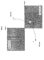
motor 108 needs to be positive, which can be used to detect the generation mode. Here, the output power PW can be expressed in a numerical formula as the followingnumerical formula 4. - Thus, the output power PW can be obtained from a relation between torque Tr and angular velocity ω. The relation is shown in a drawing as FIG.5. Here, since the torque Tr of the
motor 108 is "Tr=Kt · Iref" wherein "Kt" is a torque constant, polarity of the torque Tr can be determined by determining polarity of a current command value Iref. Since "ω" is the angular velocity of themotor 108, polarity of the angular velocity ω calculated from a Hall sensor signal obtained by a Hall sensor can be determined. Accordingly, to calculate the polarity of the output power PW, the polarity of the current instruction value Iref and the polarity of the angular velocity ω calculated based on the angular velocity ω obtained from the Hall sensor signal can be obtained. - Regarding the generation mode, when the handle is inversely operated at high speed, large back-EMF is generated and the voltage at the
motor 108 side is higher than the battery voltage Vbat, and a condition that the motor current flows from themotor 108 side to thebattery 110 side as a charging current occurs. Thus, as a condition for determining the generation mode, both condition of output power PW of the abovenumerical formula 4 and condition of anumerical formula 5 that is a condition as shown below need to be satisfied. - Here, the time constant equation is τ=L/R and P is a pole-pair number of the
motor 108. - A process of deducing the formula of the
numerical formula 5 is described below. - In FIG. 3, a route of returning to an anode of the
battery 110 starting from a cathode of thebattery 110 via an A-point, an N-point and a B-point is expressed by a relation between voltage and current as the belownumerical formula 6. - In the same way, a route of returning to the anode of the
battery 110 starting from the cathode of thebattery 110 via the A point, the N point and a C point is expressed by a relation between voltage and current as the below numerical formula 7. - Here, when a relation of "Ia+Ib+Ic=0" is used in the numerical formula 7 for modification, the formula is transformed as the below numerical formula 8.
- Here, since Ra=Rb=Rc and La=Lb=Lc are further generally established, when these relations are used, the numerical formula 8 can be expressed as numerical formula 9.
- Furthermore, when both sides of the
numerical formula 6 and the numerical formula 9 are added, the results can be expressed as the below numerical formula 10. - When both sides of the numerical formula 10 are divided by "3", the result is the below numerical formula 11.
- Here, a definition is made as follows.
- Accordingly, the numerical formula 11 becomes numerical formula 13.
motor 108.numerical formula 5 is established. - Hereinafter, preferred embodiments based on the theory will be described.
- A first embodiment of the present invention is described with reference to FIG.3 and FIG.6.
- In FIG.3, the DC
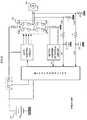
current detection circuit 30 for measuring the DC current Idc is disposed in a DC circuit that connects aDC power supply 100 to the three-phase inverter. Moreover, thecurrent detection circuit 31 and thecurrent detection circuit 32 are disposed for measuring the a-phase current Ia and the c-phase current Ic of the three-phase inverter or three-phase motor. The detected currents Idc, Ia and Ic are inputted into anarithmetic processing section 200. Thearithmetic processing section 200 sometimes comprises a microcomputer or a CPU and is processed with software, or sometimes comprises hardware. - In FIG.6, a portion enclosed by a dashed line A is corresponding to the determination means. According to a formula of Ib=Ia-Ic, the current Ib is calculated by a subtraction section 30-4 from the currents Ia and Ic inputted into the determination means A in the
arithmetic processing section 200. Next, the currents Ia, Ib and Ib are inputted into absolute-value sections 40-1, 40-2 and 40-3 respectively, and |Ia|, |Ib| and |Ic|, which are levels of the a-phase current, b-phase current and c-phase current respectively, are outputted as output from the absolute-value sections 40-1, 40-2 and 40-3. Furthermore, the |Ia|, |Ib| and |Ic|, which are the levels of the a-phase current, b-phase current and c-phase current respectively, are inputted into a maximum-value detection section 41, and the max(|Ia|, |Ib|, |Ic|), which is the maximum value in the values, is outputted. The DC current Idc detected by the DCcurrent detection circuit 30 is inputted into an absolute-value section 40-4 and the absolute value of the current |Idc| is outputted. The DCcurrent detection circuit 30 can detect DC currents in both directions. - Next, in a subtraction section 35-2, the max(|Ia|, |Ib|, |Ic|), which is the maximum current in respective phase currents, and the absolute value |Idc| of the DC current Idc are inputted, and |Idc| - max (|Ia|, |Ib|, |Ic|), which is deviation of them, is outputted. The output is inputted into an absolute-value section 40-5, and the deviation ΔI=| |Idc|-max(|Ia|, |Ib|, |Ic|)| indicated by the
numerical formula 3 is outputted. - Next, whether the deviation ΔI, which is the absolute value of difference between the maximum current value in the levels of respective motor currents Ia, Ib and Ic, and the level of the DC current Idc, is equal to or less than the determination value (errI) is determined. The deviation ΔI that is outputted from the absolute-value section 40-5 and the determination value (errI) indicated by a determination-
value setting section 42 are inputted into acomparison section 43, and then levels of them are compared. When the deviation ΔI is larger than the determination value (errI), thecomparison section 43 determines that at least one of the DCcurrent detection circuit 30 and thecurrent detection circuits current detection circuit 30 and thecurrent detection circuits - In some cases, a time delay means 44 is disposed after the
comparison section 43. The time delay means 44 is for preventing malfunction of determination means A due to noise or the like, and preferably provided though it is not indispensable requirement. Thus, even if thecomparison section 43 determines as abnormality for extremely short period, when it does not continue for a time period set by the time delay means 44 or more, it is decided as malfunction due to noise and not regarded as the failure of the current detection circuit. - Accordingly, when the first embodiment is used, the failure of the current detection circuit in the motor driving circuit of the electric power steering apparatus can be detected.
- When the DC current Idc in the generation mode cannot be measured by the DC
current detection circuit 30, the above described failure detection of the DCcurrent detection circuit 30, thecurrent detection circuit 31 and thecurrent detection circuit 32 by comparing the DC current Idc to the motor current Ia, Ib or Ic cannot be determined. Accordingly, the determination needs to be stopped during such a period. - When the current flows in the charging direction from the
motor 108 to thebattery 110, since the DCcurrent detection circuit 30 cannot measure the DC current for the functional reasons, the determination needs to be stopped to prevent malfunctions of the determination for a charging period. Judgment in the charging period is made when both of thenumerical formula 4 and thenumerical formula 5 are satisfied. Regarding thenumerical formula 4 that is a first condition, the polarity of the output power PW is determined and judged. The output power PW can be determined from the polarity of the current command value Iref and the polarity of the motor angular velocity ω calculated from the Hall sensor signal as shown in thenumerical formula 4. - The configuration of the second embodiment is shown in FIG.7.
- First, with reference to FIG.1, a Hall sensor signal from a
Hall sensor 59 provided in themotor 108 is inputted into thearithmetic processing section 200. In thearithmetic processing section 200, the Hall sensor signal is inputted into adirection detection section 50, and then the angular velocity ω is calculated and outputted. Next, the angular velocity ω is inputted into a polarity determination section 51-1, and the polarity of the angular velocity w is outputted as positive (+1) or negative (-1). - On the other hand, as shown in FIG. 7, the current command value Iref calculated from the steering torque or car speed is inputted into a
lowpass filter 52. Polarity of the current command value Iref that has passed through the low pass filter (LPF) 52 is determined in a polarity determination section 51-2, and outputted as positive (+1) or negative (-1). - Since the output power PW is the product of the current command value Iref and the angular velocity ω as shown in the
numerical formula 4, the polarity of the current command value Iref and the polarity of the angular velocity ω are inputted into amultiplication section 53, and themultiplication section 53 outputs positive (+1) when the product of the polarity of the current command value Iref and the polarity of the angular velocity ω is positive (+1), and outputs zero (0) when the product is negative (-1). - The
numerical formula 5 that is a second condition is determined. The left side of thenumerical formula 5, "4/3 · Ke/2 · ω+Imax · R · √(1+ωe 2 · τ2)" is calculated in an induced-voltage calculation section 61 to which the maximum current Imax=(max(Ia, Ib, Ic) and the angular velocity ω are inputted. The constant Ke, the winding resistance value R and the inductance value L are values determined depending on motor performance. The left side of thenumerical formula 5 and asetting section 62 indicating "2/3" of the battery voltage Vbat are compared in acomparison section 63. Although the battery voltage Vbat is typically 12 [v], if accuracy is required, the battery voltage is measured and the measured value may be used. - When the
numerical formula 5 is established (that is, the left side of thenumerical formula 5 is larger than the right side) in thecomparison section 63, thecomparison section 63 outputs positive (+1). In other cases, it outputs zero (0). NAND between "Sg1" that is an output of themultiplication section 53 and "Sg2" that is an output of thecomparison section 63 is obtained in aNAND section 70. Thus, when both of signals Sg1 and Sg2 are positive (+1), or when both formulas of thenumerical formula 4 and thenumerical formula 5 are established, or output from theNAND section 70 is zero (0), it implies that the motor is in the generation mode, and the DC current Id charges the battery. - In the case of the generation mode, the result in the determination means A, or the output from the
comparison section 43 needs to be masked. Thus, an ANDsection 71, to which the output from thecomparison section 43 that is the determination result in the determination means A and output from theNAND section 70 are inputted, is provided. When the output from theNAND section 70 is zero, even if the output from thecomparison section 43 is positive (+1) or zero (0), output from the ANDsection 71 is zero and the failure of thecurrent detection circuits NAND section 70 is positive (+1), the output from the determination means A or thecomparison section 43 becomes the output from the ANDsection 71, and the failure detection of thecurrent detection circuits section 71 is to prevent malfunction due to noise or the like. - As described hereinbefore, when the
motor 108 generates electricity and the DCcurrent detection circuit 30 cannot detect the current in the direction of charging thebattery 110, the wrong determination can be prevented by masking the determination result. Contrarily, when current is supplied from thebattery 110 into themotor 108, the advantage that the failure of the DCcurrent detection circuit 30, thecurrent detection circuit 31 and thecurrent detection circuit 32 can be surely detected can be expected. - Although the B-phase current was obtained by calculating from difference between the A-phase current and the C-phase current in the first and second embodiments, even when a B-phase current detection circuit is provided and the first and the second embodiments are practiced using the B-phase current Ib measured by the B-phase current detection circuit, the failure detection of the DC current detection circuit or the current detection circuits of respective phases can be similarly performed.
- When the invention is used, in the three-phase motor, a DC current supplied from the DC power supply is always fed from any one phase of winding of the three-phase motor and then returns to the DC power supply via the remaining two phases, or is supplied from any two phases of the winding of the three-phase motor and then returns to the DC power supply via the remaining one phase, therefore a level of DC current measured by the DC current detection circuit is compared to a level of the maximum current in respective phase currents of the three-phase motor measured by the current detection circuit, and then whether the levels are equal to each other or not is determined, thereby an advantage that failure determination of the current detection circuit is enabled can be expected.
Claims (5)
- A control device of an electric power steering apparatus in which auxiliary force for steering is added to a steering system of a vehicle by a three-phase motor driven by a three-phase inverter using a DC power supply as a driving power supply, comprising of:a DC current detection circuit for measuring a DC current supplied from the DC power supply into the three-phase inverter, at least two current detection circuits for measuring respective phase currents of the three-phase motor, and a determination means for determining whether an absolute value of difference between the maximum value in levels of the currents of respective phases and a level of the DC current is or more than a determination value or not.
- A control device of an electric power steering apparatus according to claim 1, wherein when the DC current detection circuit cannot measure a current in a direction of charging the DC power supply, determination by the determination means is stopped.
- A control device of an electric power steering apparatus according to claim 1 or 2, wherein a time delay means is provided after the determination means.
- A control device of an electric power steering apparatus according to claim 1, wherein the determination means determines a normal state when the absolute value is smaller than the determination value, and does an abnormal state when the absolute value is or more than the determination value.
- A control device of an electric power steering apparatus according to claim 1, wherein the determination means finally determines the abnormal state when a preset time passes after the determination of the abnormal state.
Applications Claiming Priority (2)
| Application Number | Priority Date | Filing Date | Title |
|---|---|---|---|
| JP2004135528A JP4506263B2 (en) | 2004-04-30 | 2004-04-30 | Control device for electric power steering device |
| JP2004135528 | 2004-04-30 |
Publications (2)
| Publication Number | Publication Date |
|---|---|
| EP1591300A1 true EP1591300A1 (en) | 2005-11-02 |
| EP1591300B1 EP1591300B1 (en) | 2007-01-24 |
Family
ID=34939486
Family Applications (1)
| Application Number | Title | Priority Date | Filing Date |
|---|---|---|---|
| EP05103334A Expired - Lifetime EP1591300B1 (en) | 2004-04-30 | 2005-04-25 | Control device of electric power steering apparatus |
Country Status (5)
| Country | Link |
|---|---|
| US (1) | US20050241875A1 (en) |
| EP (1) | EP1591300B1 (en) |
| JP (1) | JP4506263B2 (en) |
| AT (1) | ATE352451T1 (en) |
| DE (1) | DE602005000487T2 (en) |
Cited By (3)
| Publication number | Priority date | Publication date | Assignee | Title |
|---|---|---|---|---|
| FR2975244A1 (en) * | 2011-05-13 | 2012-11-16 | Michelin Soc Tech | INSTALLATION COMPRISING AN ELECTRIC ENERGY SOURCE COMPRISING AT LEAST TWO ELEMENTS OF DIFFERENT TECHNOLOGIES AND A PILOTAGE INVERTER OF AN ALTERNATING CURRENT ELECTRIC MOTOR |
| EP2058936A4 (en) * | 2006-08-30 | 2013-12-11 | Daikin Ind Ltd | CURRENT CONTROL POWER CONVERTER |
| US9190939B2 (en) | 2011-05-13 | 2015-11-17 | Compagnie Generale Des Etablissements Michelin | Device and method for managing the electric braking of a vehicle |
Families Citing this family (13)
| Publication number | Priority date | Publication date | Assignee | Title |
|---|---|---|---|---|
| JP4422567B2 (en) * | 2004-06-30 | 2010-02-24 | 株式会社日立製作所 | Motor drive device, electric actuator, and electric power steering device |
| EP1615332B1 (en) * | 2004-07-10 | 2010-11-17 | Schaeffler Technologies AG & Co. KG | Method for operating an electronically commutated motor |
| JP4738095B2 (en) * | 2005-08-17 | 2011-08-03 | 三洋電機株式会社 | Fault detection method for current detection circuit |
| US7990093B2 (en) | 2006-04-20 | 2011-08-02 | Mitsubishi Electric Corporation | Electric motor control apparatus |
| JP5102483B2 (en) * | 2006-11-29 | 2012-12-19 | プライムアースEvエナジー株式会社 | Abnormality detection device, abnormality detection method, and abnormality detection program |
| US8116945B2 (en) * | 2008-01-16 | 2012-02-14 | Jtekt Corporation | Electric power steering device |
| JP5412974B2 (en) * | 2009-03-13 | 2014-02-12 | 株式会社デンソー | Driving device for three-phase AC synchronous motor |
| JP5229644B2 (en) | 2010-06-24 | 2013-07-03 | 株式会社デンソー | Electric motor drive device and electric power steering device using the same |
| JP5229645B2 (en) | 2010-06-24 | 2013-07-03 | 株式会社デンソー | Electric motor drive device and electric power steering device using the same |
| JP5195888B2 (en) * | 2010-06-24 | 2013-05-15 | 株式会社デンソー | Electric motor drive device and electric power steering device using the same |
| CN106464190B (en) * | 2014-06-13 | 2019-04-09 | 日本精工株式会社 | Electric motor control device and electric power steering device equipped with the same |
| CN109643959B (en) * | 2017-03-09 | 2020-11-06 | 三菱电机株式会社 | Power conversion device and logic circuit |
| JP7304839B2 (en) * | 2020-07-30 | 2023-07-07 | 東芝三菱電機産業システム株式会社 | power converter |
Citations (3)
| Publication number | Priority date | Publication date | Assignee | Title |
|---|---|---|---|---|
| EP0660487A2 (en) * | 1993-12-27 | 1995-06-28 | Hitachi, Ltd. | Power supply system |
| EP0966094A2 (en) * | 1998-06-16 | 1999-12-22 | Otis Elevator Company | Curtailed operation of multiple-wound induction motor following inverter failure |
| JP2001078480A (en) * | 1999-09-07 | 2001-03-23 | Toyota Motor Corp | Abnormality detection device for motor drive device |
Family Cites Families (16)
| Publication number | Priority date | Publication date | Assignee | Title |
|---|---|---|---|---|
| JP3397007B2 (en) * | 1995-06-30 | 2003-04-14 | 松下電器産業株式会社 | Brushless motor |
| GB9810101D0 (en) * | 1998-05-13 | 1998-07-08 | Lucas Ind Plc | Improvements relating to electric motors |
| US6538404B2 (en) * | 2000-02-14 | 2003-03-25 | Sanyo Electric Co., Ltd. | Motor apparatus |
| US6381110B1 (en) * | 2000-03-06 | 2002-04-30 | General Motors Corporation | Method and apparatus for detecting isolation faults in motor/inverter systems |
| JP2002002514A (en) * | 2000-06-16 | 2002-01-09 | Unisia Jecs Corp | Abnormality judging device for electric motor drive steering auxiliary device |
| JP4465129B2 (en) * | 2000-07-14 | 2010-05-19 | パナソニック株式会社 | Brushless motor driving apparatus and driving method |
| JP2002058155A (en) * | 2000-08-11 | 2002-02-22 | Toshiba Corp | Protection relay for AC / DC converter |
| JP3749139B2 (en) * | 2001-04-23 | 2006-02-22 | 三洋電機株式会社 | Inverter protection device |
| JP3982739B2 (en) * | 2001-05-08 | 2007-09-26 | 本田技研工業株式会社 | Electric power steering device |
| JP2002354871A (en) * | 2001-05-25 | 2002-12-06 | Mitsubishi Electric Corp | Electric power steering device |
| EP2045905B1 (en) * | 2001-09-29 | 2013-06-12 | Daikin Industries, Ltd. | Phase current detection method, inverter control method, motor control method, and apparatuses used in these methods |
| JP2003237597A (en) * | 2002-02-13 | 2003-08-27 | Toyota Motor Corp | Electric power steering device |
| US6731085B2 (en) * | 2002-04-02 | 2004-05-04 | Trw Inc. | Method and apparatus for determining motor faults in an electric assist steering system |
| US6885927B2 (en) * | 2002-04-17 | 2005-04-26 | Honda Giken Kogyo Kabushiki Kaisha | Apparatus for controlling an electric power steering system |
| JP3812739B2 (en) * | 2002-05-28 | 2006-08-23 | 三菱電機株式会社 | Motor abnormality detection device and electric power steering control device |
| US6949908B2 (en) * | 2003-10-06 | 2005-09-27 | Wavecrest Laboratories, Llc | Fault-tolerant electric motor control system |
-
2004
- 2004-04-30 JP JP2004135528A patent/JP4506263B2/en not_active Expired - Fee Related
-
2005
- 2005-04-25 EP EP05103334A patent/EP1591300B1/en not_active Expired - Lifetime
- 2005-04-25 DE DE602005000487T patent/DE602005000487T2/en not_active Expired - Lifetime
- 2005-04-25 AT AT05103334T patent/ATE352451T1/en not_active IP Right Cessation
- 2005-04-29 US US11/117,496 patent/US20050241875A1/en not_active Abandoned
Patent Citations (3)
| Publication number | Priority date | Publication date | Assignee | Title |
|---|---|---|---|---|
| EP0660487A2 (en) * | 1993-12-27 | 1995-06-28 | Hitachi, Ltd. | Power supply system |
| EP0966094A2 (en) * | 1998-06-16 | 1999-12-22 | Otis Elevator Company | Curtailed operation of multiple-wound induction motor following inverter failure |
| JP2001078480A (en) * | 1999-09-07 | 2001-03-23 | Toyota Motor Corp | Abnormality detection device for motor drive device |
Non-Patent Citations (1)
| Title |
|---|
| PATENT ABSTRACTS OF JAPAN vol. 2000, no. 20 10 July 2001 (2001-07-10) * |
Cited By (4)
| Publication number | Priority date | Publication date | Assignee | Title |
|---|---|---|---|---|
| EP2058936A4 (en) * | 2006-08-30 | 2013-12-11 | Daikin Ind Ltd | CURRENT CONTROL POWER CONVERTER |
| FR2975244A1 (en) * | 2011-05-13 | 2012-11-16 | Michelin Soc Tech | INSTALLATION COMPRISING AN ELECTRIC ENERGY SOURCE COMPRISING AT LEAST TWO ELEMENTS OF DIFFERENT TECHNOLOGIES AND A PILOTAGE INVERTER OF AN ALTERNATING CURRENT ELECTRIC MOTOR |
| WO2012159884A3 (en) * | 2011-05-13 | 2013-07-25 | Compagnie Generale Des Etablissements Michelin | Unit comprising an electric power source including at least two elements of different technologies and an inverter for controlling an alternating-current electric motor |
| US9190939B2 (en) | 2011-05-13 | 2015-11-17 | Compagnie Generale Des Etablissements Michelin | Device and method for managing the electric braking of a vehicle |
Also Published As
| Publication number | Publication date |
|---|---|
| US20050241875A1 (en) | 2005-11-03 |
| DE602005000487D1 (en) | 2007-03-15 |
| JP2005313807A (en) | 2005-11-10 |
| EP1591300B1 (en) | 2007-01-24 |
| ATE352451T1 (en) | 2007-02-15 |
| DE602005000487T2 (en) | 2007-10-31 |
| JP4506263B2 (en) | 2010-07-21 |
Similar Documents
| Publication | Publication Date | Title |
|---|---|---|
| EP1591300B1 (en) | Control device of electric power steering apparatus | |
| CN103959638B (en) | Driven steering device | |
| CN105934879B (en) | Motor control device, electric power steering device using same, and vehicle | |
| JP6458884B2 (en) | Electronic control device and electric power steering device equipped with the same | |
| US12005975B2 (en) | Method for providing steering assistance for an electromechanical steering system of a motor vehicle comprising a redundantly designed control device | |
| JP5157429B2 (en) | Electric power steering device | |
| US10605837B2 (en) | Abnormality diagnosis apparatus | |
| CN104584423B (en) | Motor control device, electric power steering device using same, and vehicle | |
| US7837004B2 (en) | Steering assisting system for vehicle | |
| US10177694B2 (en) | Current sensor abnormality diagnosis device | |
| KR101885842B1 (en) | Electric power steering device | |
| CN105981291A (en) | Motor control device, electric power steering device using the motor control device, and vehicle | |
| US20060043917A1 (en) | Electromotive power steering system | |
| KR100386174B1 (en) | Apparatus for detecting abnormality of motor driving device for steering of vehicle | |
| US20110163708A1 (en) | Motor drive apparatus and electric power steering apparatus using the same | |
| JP2023018750A (en) | steering system | |
| US12043325B2 (en) | Redundant control unit for a motor vehicle steering system | |
| JPH04110272A (en) | Motor-driven type power steering device | |
| JP2019137374A (en) | Power-supply device and power-supply system |
Legal Events
| Date | Code | Title | Description |
|---|---|---|---|
| PUAI | Public reference made under article 153(3) epc to a published international application that has entered the european phase |
Free format text: ORIGINAL CODE: 0009012 |
|
| AK | Designated contracting states |
Kind code of ref document: A1 Designated state(s): AT BE BG CH CY CZ DE DK EE ES FI FR GB GR HU IE IS IT LI LT LU MC NL PL PT RO SE SI SK TR |
|
| AX | Request for extension of the european patent |
Extension state: AL BA HR LV MK YU |
|
| RAP1 | Party data changed (applicant data changed or rights of an application transferred) |
Owner name: NSK STEERING SYSTEMS CO. LTD Owner name: NSK LTD. |
|
| 17P | Request for examination filed |
Effective date: 20060420 |
|
| AKX | Designation fees paid |
Designated state(s): AT BE BG CH CY CZ DE DK EE ES FI FR GB GR HU IE IS IT LI LT LU MC NL PL PT RO SE SI SK TR |
|
| GRAP | Despatch of communication of intention to grant a patent |
Free format text: ORIGINAL CODE: EPIDOSNIGR1 |
|
| GRAS | Grant fee paid |
Free format text: ORIGINAL CODE: EPIDOSNIGR3 |
|
| GRAA | (expected) grant |
Free format text: ORIGINAL CODE: 0009210 |
|
| AK | Designated contracting states |
Kind code of ref document: B1 Designated state(s): AT BE BG CH CY CZ DE DK EE ES FI FR GB GR HU IE IS IT LI LT LU MC NL PL PT RO SE SI SK TR |
|
| PG25 | Lapsed in a contracting state [announced via postgrant information from national office to epo] |
Ref country code: FI Free format text: LAPSE BECAUSE OF FAILURE TO SUBMIT A TRANSLATION OF THE DESCRIPTION OR TO PAY THE FEE WITHIN THE PRESCRIBED TIME-LIMIT Effective date: 20070124 Ref country code: CH Free format text: LAPSE BECAUSE OF FAILURE TO SUBMIT A TRANSLATION OF THE DESCRIPTION OR TO PAY THE FEE WITHIN THE PRESCRIBED TIME-LIMIT Effective date: 20070124 Ref country code: AT Free format text: LAPSE BECAUSE OF FAILURE TO SUBMIT A TRANSLATION OF THE DESCRIPTION OR TO PAY THE FEE WITHIN THE PRESCRIBED TIME-LIMIT Effective date: 20070124 Ref country code: DK Free format text: LAPSE BECAUSE OF FAILURE TO SUBMIT A TRANSLATION OF THE DESCRIPTION OR TO PAY THE FEE WITHIN THE PRESCRIBED TIME-LIMIT Effective date: 20070124 Ref country code: SI Free format text: LAPSE BECAUSE OF FAILURE TO SUBMIT A TRANSLATION OF THE DESCRIPTION OR TO PAY THE FEE WITHIN THE PRESCRIBED TIME-LIMIT Effective date: 20070124 Ref country code: LI Free format text: LAPSE BECAUSE OF FAILURE TO SUBMIT A TRANSLATION OF THE DESCRIPTION OR TO PAY THE FEE WITHIN THE PRESCRIBED TIME-LIMIT Effective date: 20070124 Ref country code: NL Free format text: LAPSE BECAUSE OF FAILURE TO SUBMIT A TRANSLATION OF THE DESCRIPTION OR TO PAY THE FEE WITHIN THE PRESCRIBED TIME-LIMIT Effective date: 20070124 Ref country code: PL Free format text: LAPSE BECAUSE OF FAILURE TO SUBMIT A TRANSLATION OF THE DESCRIPTION OR TO PAY THE FEE WITHIN THE PRESCRIBED TIME-LIMIT Effective date: 20070124 |
|
| REG | Reference to a national code |
Ref country code: GB Ref legal event code: FG4D |
|
| REG | Reference to a national code |
Ref country code: CH Ref legal event code: EP |
|
| REG | Reference to a national code |
Ref country code: IE Ref legal event code: FG4D |
|
| REF | Corresponds to: |
Ref document number: 602005000487 Country of ref document: DE Date of ref document: 20070315 Kind code of ref document: P |
|
| PG25 | Lapsed in a contracting state [announced via postgrant information from national office to epo] |
Ref country code: BG Free format text: LAPSE BECAUSE OF FAILURE TO SUBMIT A TRANSLATION OF THE DESCRIPTION OR TO PAY THE FEE WITHIN THE PRESCRIBED TIME-LIMIT Effective date: 20070424 Ref country code: SE Free format text: LAPSE BECAUSE OF FAILURE TO SUBMIT A TRANSLATION OF THE DESCRIPTION OR TO PAY THE FEE WITHIN THE PRESCRIBED TIME-LIMIT Effective date: 20070424 |
|
| PG25 | Lapsed in a contracting state [announced via postgrant information from national office to epo] |
Ref country code: ES Free format text: LAPSE BECAUSE OF FAILURE TO SUBMIT A TRANSLATION OF THE DESCRIPTION OR TO PAY THE FEE WITHIN THE PRESCRIBED TIME-LIMIT Effective date: 20070505 |
|
| PG25 | Lapsed in a contracting state [announced via postgrant information from national office to epo] |
Ref country code: IS Free format text: LAPSE BECAUSE OF FAILURE TO SUBMIT A TRANSLATION OF THE DESCRIPTION OR TO PAY THE FEE WITHIN THE PRESCRIBED TIME-LIMIT Effective date: 20070524 |
|
| ET | Fr: translation filed | ||
| PG25 | Lapsed in a contracting state [announced via postgrant information from national office to epo] |
Ref country code: PT Free format text: LAPSE BECAUSE OF FAILURE TO SUBMIT A TRANSLATION OF THE DESCRIPTION OR TO PAY THE FEE WITHIN THE PRESCRIBED TIME-LIMIT Effective date: 20070625 |
|
| REG | Reference to a national code |
Ref country code: CH Ref legal event code: PL |
|
| NLV1 | Nl: lapsed or annulled due to failure to fulfill the requirements of art. 29p and 29m of the patents act | ||
| PG25 | Lapsed in a contracting state [announced via postgrant information from national office to epo] |
Ref country code: SK Free format text: LAPSE BECAUSE OF FAILURE TO SUBMIT A TRANSLATION OF THE DESCRIPTION OR TO PAY THE FEE WITHIN THE PRESCRIBED TIME-LIMIT Effective date: 20070124 |
|
| PLBE | No opposition filed within time limit |
Free format text: ORIGINAL CODE: 0009261 |
|
| STAA | Information on the status of an ep patent application or granted ep patent |
Free format text: STATUS: NO OPPOSITION FILED WITHIN TIME LIMIT |
|
| 26N | No opposition filed |
Effective date: 20071025 |
|
| PG25 | Lapsed in a contracting state [announced via postgrant information from national office to epo] |
Ref country code: CZ Free format text: LAPSE BECAUSE OF FAILURE TO SUBMIT A TRANSLATION OF THE DESCRIPTION OR TO PAY THE FEE WITHIN THE PRESCRIBED TIME-LIMIT Effective date: 20070124 Ref country code: BE Free format text: LAPSE BECAUSE OF FAILURE TO SUBMIT A TRANSLATION OF THE DESCRIPTION OR TO PAY THE FEE WITHIN THE PRESCRIBED TIME-LIMIT Effective date: 20070124 Ref country code: RO Free format text: LAPSE BECAUSE OF FAILURE TO SUBMIT A TRANSLATION OF THE DESCRIPTION OR TO PAY THE FEE WITHIN THE PRESCRIBED TIME-LIMIT Effective date: 20070124 |
|
| PG25 | Lapsed in a contracting state [announced via postgrant information from national office to epo] |
Ref country code: LT Free format text: LAPSE BECAUSE OF FAILURE TO SUBMIT A TRANSLATION OF THE DESCRIPTION OR TO PAY THE FEE WITHIN THE PRESCRIBED TIME-LIMIT Effective date: 20070124 |
|
| PG25 | Lapsed in a contracting state [announced via postgrant information from national office to epo] |
Ref country code: IT Free format text: LAPSE BECAUSE OF FAILURE TO SUBMIT A TRANSLATION OF THE DESCRIPTION OR TO PAY THE FEE WITHIN THE PRESCRIBED TIME-LIMIT Effective date: 20070124 Ref country code: GR Free format text: LAPSE BECAUSE OF FAILURE TO SUBMIT A TRANSLATION OF THE DESCRIPTION OR TO PAY THE FEE WITHIN THE PRESCRIBED TIME-LIMIT Effective date: 20070425 |
|
| PG25 | Lapsed in a contracting state [announced via postgrant information from national office to epo] |
Ref country code: IE Free format text: LAPSE BECAUSE OF NON-PAYMENT OF DUE FEES Effective date: 20070425 |
|
| PG25 | Lapsed in a contracting state [announced via postgrant information from national office to epo] |
Ref country code: EE Free format text: LAPSE BECAUSE OF FAILURE TO SUBMIT A TRANSLATION OF THE DESCRIPTION OR TO PAY THE FEE WITHIN THE PRESCRIBED TIME-LIMIT Effective date: 20070124 |
|
| PG25 | Lapsed in a contracting state [announced via postgrant information from national office to epo] |
Ref country code: MC Free format text: LAPSE BECAUSE OF NON-PAYMENT OF DUE FEES Effective date: 20070430 |
|
| PG25 | Lapsed in a contracting state [announced via postgrant information from national office to epo] |
Ref country code: CY Free format text: LAPSE BECAUSE OF FAILURE TO SUBMIT A TRANSLATION OF THE DESCRIPTION OR TO PAY THE FEE WITHIN THE PRESCRIBED TIME-LIMIT Effective date: 20070124 |
|
| PG25 | Lapsed in a contracting state [announced via postgrant information from national office to epo] |
Ref country code: LU Free format text: LAPSE BECAUSE OF NON-PAYMENT OF DUE FEES Effective date: 20070425 |
|
| PG25 | Lapsed in a contracting state [announced via postgrant information from national office to epo] |
Ref country code: TR Free format text: LAPSE BECAUSE OF FAILURE TO SUBMIT A TRANSLATION OF THE DESCRIPTION OR TO PAY THE FEE WITHIN THE PRESCRIBED TIME-LIMIT Effective date: 20070124 Ref country code: HU Free format text: LAPSE BECAUSE OF FAILURE TO SUBMIT A TRANSLATION OF THE DESCRIPTION OR TO PAY THE FEE WITHIN THE PRESCRIBED TIME-LIMIT Effective date: 20070725 |
|
| GBPC | Gb: european patent ceased through non-payment of renewal fee |
Effective date: 20090425 |
|
| PG25 | Lapsed in a contracting state [announced via postgrant information from national office to epo] |
Ref country code: GB Free format text: LAPSE BECAUSE OF NON-PAYMENT OF DUE FEES Effective date: 20090425 |
|
| REG | Reference to a national code |
Ref country code: FR Ref legal event code: PLFP Year of fee payment: 12 |
|
| REG | Reference to a national code |
Ref country code: FR Ref legal event code: PLFP Year of fee payment: 13 |
|
| REG | Reference to a national code |
Ref country code: FR Ref legal event code: PLFP Year of fee payment: 14 |
|
| PGFP | Annual fee paid to national office [announced via postgrant information from national office to epo] |
Ref country code: FR Payment date: 20200312 Year of fee payment: 16 |
|
| PGFP | Annual fee paid to national office [announced via postgrant information from national office to epo] |
Ref country code: DE Payment date: 20200415 Year of fee payment: 16 |
|
| REG | Reference to a national code |
Ref country code: DE Ref legal event code: R119 Ref document number: 602005000487 Country of ref document: DE |
|
| PG25 | Lapsed in a contracting state [announced via postgrant information from national office to epo] |
Ref country code: DE Free format text: LAPSE BECAUSE OF NON-PAYMENT OF DUE FEES Effective date: 20211103 Ref country code: FR Free format text: LAPSE BECAUSE OF NON-PAYMENT OF DUE FEES Effective date: 20210430 |