EP1591294A2 - Cover assembly for fuel tank - Google Patents
Cover assembly for fuel tank Download PDFInfo
- Publication number
- EP1591294A2 EP1591294A2 EP05075987A EP05075987A EP1591294A2 EP 1591294 A2 EP1591294 A2 EP 1591294A2 EP 05075987 A EP05075987 A EP 05075987A EP 05075987 A EP05075987 A EP 05075987A EP 1591294 A2 EP1591294 A2 EP 1591294A2
- Authority
- EP
- European Patent Office
- Prior art keywords
- cover assembly
- cover
- fuel
- set forth
- insert
- Prior art date
- Legal status (The legal status is an assumption and is not a legal conclusion. Google has not performed a legal analysis and makes no representation as to the accuracy of the status listed.)
- Withdrawn
Links
Images

Classifications
-
- B—PERFORMING OPERATIONS; TRANSPORTING
- B60—VEHICLES IN GENERAL
- B60K—ARRANGEMENT OR MOUNTING OF PROPULSION UNITS OR OF TRANSMISSIONS IN VEHICLES; ARRANGEMENT OR MOUNTING OF PLURAL DIVERSE PRIME-MOVERS IN VEHICLES; AUXILIARY DRIVES FOR VEHICLES; INSTRUMENTATION OR DASHBOARDS FOR VEHICLES; ARRANGEMENTS IN CONNECTION WITH COOLING, AIR INTAKE, GAS EXHAUST OR FUEL SUPPLY OF PROPULSION UNITS IN VEHICLES
- B60K15/00—Arrangement in connection with fuel supply of combustion engines or other fuel consuming energy converters, e.g. fuel cells; Mounting or construction of fuel tanks
- B60K15/03—Fuel tanks
- B60K15/03177—Fuel tanks made of non-metallic material, e.g. plastics, or of a combination of non-metallic and metallic material
-
- F—MECHANICAL ENGINEERING; LIGHTING; HEATING; WEAPONS; BLASTING
- F02—COMBUSTION ENGINES; HOT-GAS OR COMBUSTION-PRODUCT ENGINE PLANTS
- F02M—SUPPLYING COMBUSTION ENGINES IN GENERAL WITH COMBUSTIBLE MIXTURES OR CONSTITUENTS THEREOF
- F02M37/00—Apparatus or systems for feeding liquid fuel from storage containers to carburettors or fuel-injection apparatus; Arrangements for purifying liquid fuel specially adapted for, or arranged on, internal-combustion engines
- F02M37/04—Feeding by means of driven pumps
- F02M37/08—Feeding by means of driven pumps electrically driven
- F02M37/10—Feeding by means of driven pumps electrically driven submerged in fuel, e.g. in reservoir
- F02M37/103—Mounting pumps on fuel tanks
-
- B—PERFORMING OPERATIONS; TRANSPORTING
- B60—VEHICLES IN GENERAL
- B60K—ARRANGEMENT OR MOUNTING OF PROPULSION UNITS OR OF TRANSMISSIONS IN VEHICLES; ARRANGEMENT OR MOUNTING OF PLURAL DIVERSE PRIME-MOVERS IN VEHICLES; AUXILIARY DRIVES FOR VEHICLES; INSTRUMENTATION OR DASHBOARDS FOR VEHICLES; ARRANGEMENTS IN CONNECTION WITH COOLING, AIR INTAKE, GAS EXHAUST OR FUEL SUPPLY OF PROPULSION UNITS IN VEHICLES
- B60K15/00—Arrangement in connection with fuel supply of combustion engines or other fuel consuming energy converters, e.g. fuel cells; Mounting or construction of fuel tanks
- B60K15/01—Arrangement of fuel conduits
-
- B—PERFORMING OPERATIONS; TRANSPORTING
- B60—VEHICLES IN GENERAL
- B60K—ARRANGEMENT OR MOUNTING OF PROPULSION UNITS OR OF TRANSMISSIONS IN VEHICLES; ARRANGEMENT OR MOUNTING OF PLURAL DIVERSE PRIME-MOVERS IN VEHICLES; AUXILIARY DRIVES FOR VEHICLES; INSTRUMENTATION OR DASHBOARDS FOR VEHICLES; ARRANGEMENTS IN CONNECTION WITH COOLING, AIR INTAKE, GAS EXHAUST OR FUEL SUPPLY OF PROPULSION UNITS IN VEHICLES
- B60K15/00—Arrangement in connection with fuel supply of combustion engines or other fuel consuming energy converters, e.g. fuel cells; Mounting or construction of fuel tanks
- B60K15/03—Fuel tanks
- B60K2015/03105—Fuel tanks with supplementary interior tanks inside the fuel tank
-
- B—PERFORMING OPERATIONS; TRANSPORTING
- B60—VEHICLES IN GENERAL
- B60K—ARRANGEMENT OR MOUNTING OF PROPULSION UNITS OR OF TRANSMISSIONS IN VEHICLES; ARRANGEMENT OR MOUNTING OF PLURAL DIVERSE PRIME-MOVERS IN VEHICLES; AUXILIARY DRIVES FOR VEHICLES; INSTRUMENTATION OR DASHBOARDS FOR VEHICLES; ARRANGEMENTS IN CONNECTION WITH COOLING, AIR INTAKE, GAS EXHAUST OR FUEL SUPPLY OF PROPULSION UNITS IN VEHICLES
- B60K15/00—Arrangement in connection with fuel supply of combustion engines or other fuel consuming energy converters, e.g. fuel cells; Mounting or construction of fuel tanks
- B60K15/03—Fuel tanks
- B60K2015/03328—Arrangements or special measures related to fuel tanks or fuel handling
- B60K2015/03453—Arrangements or special measures related to fuel tanks or fuel handling for fixing or mounting parts of the fuel tank together
Definitions
- each material for the cover has its advantages and disadvantages.
- the metal material for the cover is stronger and has the lowest permeation of fuel vapors.
- the metal material for the cover may produce leaks when fabricated, cannot provide many features, and is relatively costly to make.
- the plastic material for the cover is easy to produce without leaks, easier to provide many features, and is cheaper.
- the plastic material has a relatively high permeability when used with fuels and is weaker in strength than metal material.
- the present invention is a cover assembly for a fuel tank of a vehicle including a cover made of a metal material adapted to close an opening in the fuel tank having a fuel reservoir disposed therein and an insert molded to the cover to form a plurality of members to allow components to be attached thereto.
- the insert is integral, unitary, and one-piece.
- the cover assembly 10 is part of a fuel delivery module, generally indicated at 32.
- the fuel delivery module 32 is disposed in the fuel tank 12 to deliver fuel from the fuel tank 12 to an engine (not shown) of the vehicle.
- the fuel delivery module 32 includes a reservoir assembly 34 having an electrical fuel pump 36 mounted therein.
- the fuel delivery module 32 also includes a fuel level indication mechanism 38 such as a rheostat connected to the reservoir assembly 34 for indicating the level of the fuel inside the fuel tank 12.
- the fuel delivery module 32 further includes a plurality of guide rods or tubes 40 to mechanically connect the cover assembly 10 with the reservoir assembly 34. It should be appreciated that, in other types of fuel delivery modules, there is no mechanical connection between the cover assembly 10 and the reservoir assembly 34 and this type of module requires a retaining mechanism on the bottom of the fuel tank 12.
- the cover assembly 10 includes a cover 42 to cover or close the opening 30.
- the cover 42 is generally circular in shape.
- the cover 42 includes a base wall 44 having a raised portion 46.
- the raised portion 46 has at least one, preferably a plurality of apertures 48,50 extending therethrough for a function to be described.
- the cover 42 also includes a flange wall 52 extending underneath and generally parallel to the base wall 44.
- the cover 42 is made from a metal material such as steel.
- the cover 42 is a stamped steel cover.
- the cover assembly 10 may include at least one, preferably a plurality of electrical terminals 88 extending into the electrical connector 74.
- the electrical terminals 88 are made of a metal material.
- the electrical terminals 88 extend into the cavities 78 and 82 of the interior portion 76 and exterior portion 80. It should be appreciated that the electrical terminals 88 are insert molded into the electrical connector 74. It should also be appreciated that the insert 54 may be extended to other components such as pressure regulators, pressure relief valves, etc.
- the cover assembly 110 includes the metal cover 142 and plastic insert 154.
- the plastic insert 154 has the guide rod retaining bosses 162, the tube end-forms 164, and the electrical connector 174.
- the cover assembly 110 also includes the fuel tubes 184 and electrical terminals 188.
- the metal fuel tubes 184 are insert molded to the insert 154.
- the cover 142 eliminates the stepped flange about the aperture 148.
- the cover assembly 210 includes the metal cover 242 and plastic insert 254.
- the plastic insert 254 has the guide rod retaining bosses 262, the tube end-forms 264, and the electrical connector 274.
- the cover assembly 110 also includes the electrical terminals 288.
- the cover 242 eliminates the raised portion and stepped flange about the aperture 248.
- the cover 242 includes a generally planar base wall 244.
- the base wall 244 is a punched plate with minimal plating requirements.
- the insert 254 has an upper wall portion 292 extending radially over the cover 242.
Abstract
Description
- The present invention relates generally to fuel tanks for vehicles and, more particularly, to a cover assembly for a fuel tank of a vehicle.
- It is known to provide a fuel tank in a vehicle to hold fuel to be used by an engine of the vehicle. In such a fuel tank, a fuel delivery module is provided with a cover to seal the opening through which the fuel delivery module has been assembled into the fuel tank. In some cases, the fuel delivery module consists only of a cover/flange to which either an electrical fuel pump and/or a mechanism for indicating fuel is attached. Recently, the trend has been to construct fuel delivery modules with an integral fuel reservoir. Various valves, sensors, pressure regulators, as well as filters have been added over time. Several of these components have been mounted or attached to the cover. Typically, the cover has fuel tubes, an electrical connector, and a rollover valve attached thereto. The cover is made entirely out of either a metal material or a plastic material.
- Each material for the cover has its advantages and disadvantages. For example, the metal material for the cover is stronger and has the lowest permeation of fuel vapors. However, the metal material for the cover may produce leaks when fabricated, cannot provide many features, and is relatively costly to make. On the other hand, the plastic material for the cover is easy to produce without leaks, easier to provide many features, and is cheaper. However, the plastic material has a relatively high permeability when used with fuels and is weaker in strength than metal material.
- Therefore, it is desirable to provide a cover assembly for a fuel tank that reduces permeation of fuel therethrough. It is also desirable to increase the strength of a cover assembly for a fuel tank. It is further desirable to provide a plurality of molded features in a cover assembly for a fuel tank, which reduces the component part count and number of assembly operations. Therefore, there is a need in the art to provide a cover assembly that meets these desires.
- Accordingly, the present invention is a cover assembly for a fuel tank of a vehicle including a cover made of a metal material adapted to close an opening in the fuel tank having a fuel reservoir disposed therein and an insert molded to the cover to form a plurality of members to allow components to be attached thereto. The insert is integral, unitary, and one-piece.
- One advantage of the present invention is that a new cover assembly is provided for a fuel tank of a vehicle that includes a metal cover insert molded into a plastic cover. Another advantage of the present invention is that the cover assembly has a metal cover and a plastic carrier used in conjunction with the metal cover to minimize permeation and to increase strength. Yet another advantage of the present invention is that the cover assembly provides plastic molded features to a metal fuel cover for a fuel delivery module. A further advantage of the present invention is that the cover assembly reduces cost by reducing the component part count and number of assembly operations.
- Other features and advantages of the present invention will be readily appreciated, as the same becomes better understood, after reading the subsequent description taken in conjunction with the accompanying drawings.
-
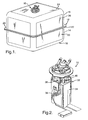
- Figure 1 is a perspective view of a cover assembly for a fuel delivery module, according to the present invention, illustrated in operational relationship with a fuel tank.
- Figure 2 is a perspective view of the cover assembly and fuel delivery module of Figure 1.
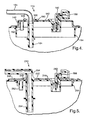
- Figure 3 is a fragmentary elevational view of the cover assembly of Figure 1.
- Figure 4 is a fragmentary elevational view of another embodiment, according to the present invention, of the cover assembly of Figure 1.
- Figure 5 is a fragmentary elevational view of yet another embodiment, according to the present invention, of the cover assembly of Figure 1.
-
- Referring to the drawings and in particular Figures 1 through 3, one embodiment of a
cover assembly 10, according to the present invention, is shown for afuel tank 12 of a vehicle (not shown). In the embodiment illustrated, thefuel tank 12 includes a first orlower half shell 14 and a second orupper half shell 16. Thelower half shell 14 has abase wall 18 and aside wall 20 around a periphery of thebase wall 18 and extending generally perpendicular thereto. Theside wall 20 has aflange 22 extending outwardly and generally perpendicular thereto. Theupper half shell 16 has abase wall 24 and aside wall 26 around a periphery of thebase wall 24 and extending generally perpendicular thereto. Theside wall 26 has aflange 28 extending outwardly and generally perpendicular thereto. Theflanges lower half shell 14 andupper half shell 16, respectively, are joined together by suitable means such as by welding. Thelower half shell 14 andupper half shell 16 are made of a rigid material such as plastic. Thebase wall 24 of theupper half shell 16 includes an opening 30 for thecover assembly 10. It should be appreciated that, except for thecover assembly 10, thefuel tank 12 is conventional and known in the art. - As illustrated in Figure 2, the
cover assembly 10 is part of a fuel delivery module, generally indicated at 32. Thefuel delivery module 32 is disposed in thefuel tank 12 to deliver fuel from thefuel tank 12 to an engine (not shown) of the vehicle. Thefuel delivery module 32 includes areservoir assembly 34 having anelectrical fuel pump 36 mounted therein. Thefuel delivery module 32 also includes a fuellevel indication mechanism 38 such as a rheostat connected to thereservoir assembly 34 for indicating the level of the fuel inside thefuel tank 12. Thefuel delivery module 32 further includes a plurality of guide rods ortubes 40 to mechanically connect thecover assembly 10 with thereservoir assembly 34. It should be appreciated that, in other types of fuel delivery modules, there is no mechanical connection between thecover assembly 10 and thereservoir assembly 34 and this type of module requires a retaining mechanism on the bottom of thefuel tank 12. - Referring to Figure 3, the
cover assembly 10 includes acover 42 to cover or close theopening 30. Thecover 42 is generally circular in shape. Thecover 42 includes abase wall 44 having a raisedportion 46. The raisedportion 46 has at least one, preferably a plurality ofapertures cover 42 also includes aflange wall 52 extending underneath and generally parallel to thebase wall 44. Thecover 42 is made from a metal material such as steel. Preferably, thecover 42 is a stamped steel cover. - The
cover assembly 10 also includes aninsert 54 molded to thecover 42. Theinsert 54 is generally circular in shape. Theinsert 54 has abase wall 50 that is generally planar and circular in shape. Thebase wall 56 has a raisedportion 58 for a function to be described. Thebase wall 56 is disposed adjacent thebase wall 44 of thecover 42 and the raisedportion 58 is disposed adjacent the raisedportion 46 of thecover 42. Theinsert 54 also includes aside wall 60 extending generally perpendicular from thebase wall 56. Theside wall 60 forms a skirt of thecover assembly 10. - The
insert 54 includes at least one, preferably a plurality of guiderod retaining bosses 62. The guiderod retaining bosses 62 are generally cylindrical and circular in shape. The guiderod retaining bosses 62 have acavity 63 extending axially therein to receive and retain theguide rods 40. The guiderod retaining bosses 62 extend axially from aninterior surface 65 of the raisedportion 58 of theinsert 54. It should be appreciated that the guiderod retaining bosses 62 provide rotational flexibility in the attachment of thecover assembly 10 with thereservoir assembly 34. It should also be appreciated that the guiderod retaining bosses 62 are optional and that theguide rods 40 may be molded directly to thecover 42. - The
carrier 58 may include at least one, preferably a plurality of tube end-forms 64 disposed about at least one of theapertures 48 in thecover 42 and extending axially for a function to be described. The tube end-form 64 is generally cylindrical and circular in shape. The tube end-form 64 has apassageway 66 extending therethrough. The tube end-form 64 extends axially from theinterior surface 65 of the raisedportion 58 of theinsert 54. The tube end-form 64 has a steppedrecess 68 at an upper end to receive a steppedflange 70 of thecover 42 forming theaperture 48. The tube end-form 64 has aflange 72 extending radially and annularly near a lower end thereof. - The
insert 54 also includes anelectrical connector 74 extending into and through theaperture 50 of thecover 42. Theelectrical connector 74 has aninterior portion 76 that is generally cylindrical and circular in shape. Theinterior portion 76 has at least one, preferably a plurality ofcavities 78 extending axially therein for a function to be described. Theinterior portion 78 extends axially from aninterior surface 65 of the raisedportion 58 of theinsert 54. Theelectrical connector 74 has anexterior portion 80 that is generally cylindrical and inverted "L" in shape. Theexterior portion 80 has at least one, preferably a plurality ofcavities 82 extending radially therein for a function to be described. Theexterior portion 80 extends axially from the raisedportion 58 of theinsert 54. It should be appreciated that theinterior portion 76 andexterior portion 80 are integral, unitary, and one-piece. - The
insert 54 is made from a plastic material such as a polyethylene. It should be appreciated that theinsert 54 is a monolithic structure being integral, unitary, and one-piece. - The
cover assembly 10 may include at least one, preferably a plurality offuel tubes 84 extending into and through theapertures 48 of thecover 42. Thefuel tubes 84 are made of a metal material. Thefuel tube 84 has a projection orflange 86 extending radially and abutting the steppedflange 70 to limit the insertion of thefuel tube 84 through theaperture 48 and into thepassageway 66 of the tube end-form 64. Thefuel tubes 84 are connected or assembled to thecover 42 by suitable means such as brazing, soldering, welding, or mechanical retention. - The
cover assembly 10 may include at least one, preferably a plurality ofelectrical terminals 88 extending into theelectrical connector 74. Theelectrical terminals 88 are made of a metal material. Theelectrical terminals 88 extend into thecavities interior portion 76 andexterior portion 80. It should be appreciated that theelectrical terminals 88 are insert molded into theelectrical connector 74. It should also be appreciated that theinsert 54 may be extended to other components such as pressure regulators, pressure relief valves, etc. - Referring to FIG. 4, another embodiment, according to the present invention, of the
cover assembly 10 is shown. Like parts of thecover assembly 10 have like reference numerals increased by one hundred (100). In this embodiment, thecover assembly 110 includes themetal cover 142 andplastic insert 154. Theplastic insert 154 has the guiderod retaining bosses 162, the tube end-forms 164, and the electrical connector 174. Thecover assembly 110 also includes thefuel tubes 184 andelectrical terminals 188. However, themetal fuel tubes 184 are insert molded to theinsert 154. Thecover 142 eliminates the stepped flange about theaperture 148. Theinsert 154 has anend portion 190 extending axially from the tube end-form 164 through theaperture 148 and radially over a portion of the raisedportion 142 of thecover 142. Theend portion 190 is disposed about theprojection 186 of thefuel tube 184 to retain thefuel tube 184 therein. It should be appreciated that the operation of thecover assembly 110 is similar to thecover assembly 10. - Referring to FIG. 5, yet another embodiment, according to the present invention, of the
cover assembly 10 is shown. Like parts of thecover assembly 10 have like reference numerals increased by two hundred (200). In this embodiment, thecover assembly 210 includes themetal cover 242 andplastic insert 254. Theplastic insert 254 has the guiderod retaining bosses 262, the tube end-forms 264, and the electrical connector 274. Thecover assembly 110 also includes theelectrical terminals 288. Thecover 242 eliminates the raised portion and stepped flange about theaperture 248. Thecover 242 includes a generallyplanar base wall 244. Thebase wall 244 is a punched plate with minimal plating requirements. Theinsert 254 has anupper wall portion 292 extending radially over thecover 242. Theinsert 254 also has afuel tube portion 294 extending axially from the tube end-form 264 through theaperture 248 and forms a generally inverted "L" shape. The tube end-form 264 andfuel tube portion 294 are integral, unitary, and one-piece to form a molded fuel tube. It should be appreciated that the operation of thecover assembly 210 is similar to thecover assembly 10. It should also be appreciated that thecover assembly 210 reduces the manufacturing processes to those of a current production plastic cover. - Accordingly, the cover assembly 10,110,210 provides 100% of the metal cover's strength and is insert molded to add several complex features in one molding step. Although the cover assembly 10,110,210 goes through all of the metal cover manufacturing steps (brazing, welding, and plating) and added assembly steps are eliminated by molding the skirt, guide-boss (or complete guide rod), under-cover tube end-form, and electrical connector tight into the cover. It should be appreciated that other features may be molded such as latches for a fuel limiting vent valve (not shown) and/or grade vent valve, or even the valve body for the fuel limiting vent valve or grade vent valve. The present invention has been described in an illustrative manner. It is to be understood that the terminology, which has been used, is intended to be in the nature of words of description rather than of limitation.
- Many modifications and variations of the present invention are possible in light of the above teachings. Therefore, within the scope of the appended claims, the present invention may be practiced other than as specifically described.
Claims (23)
- A cover assembly (10,110,210) for a fuel tank (12) of a vehicle comprising:a cover (42,142,242) made of a metal material adapted to close an opening (30) in the fuel tank (12) having a fuel reservoir (34) disposed therein; andan insert (54,154,254) molded to said cover (42,142,242) to form a plurality of members to allow components to be attached thereto, said insert (54,154,254) being integral, unitary, and one-piece.
- A cover assembly (10,110,210) as set forth in claim 1 wherein said insert (54,154,254) is made of a plastic material.
- A cover assembly (10,110,210) as set forth in claim 1 wherein said insert (54,154,254) has a base wall (58,158,258) and a side wall (60,160,260) extending from said base wall (58,158,258).
- A cover assembly (10,110,210) as set forth in claim 3 wherein said one of said members comprises at least one guide rod retaining boss (62,162,262) extending from said base wall (58,158,258) and having a cavity therein to receive a guide rod (40) of the fuel reservoir (34).
- A cover assembly (10,110,210) as set forth in claim 3 wherein said cover (42,142,242) has a plurality of aperture (48,148,248) extending therethrough.
- A cover assembly (10,110,210) as set forth in claim 5 wherein at least one of said members comprises a tube end-form (64,164,264) extending from said base wall (58,158,258) and having a passageway extending therethrough to receive a fuel tube (84,184) communicating with at least one of said aperture (48,148).
- A cover assembly (10,110,210) as set forth in claim 6 including a fuel tube (84,184) communicating with said tube end-form (64,164,264).
- A cover assembly (10,110,210) as set forth in claim 7 wherein said tube end-form (164) is disposed about an end of said fuel tube (184) to retain said fuel tube (84,184) to said insert (154).
- A cover assembly (10,110,210) as set forth in claim 7 wherein said tube end-form (264) and said fuel tube are integral unitary, and one-piece.
- A cover assembly (10,110,210) as set forth in claim 5 wherein at least one said members comprises an electrical connector (74,174,274) extending through at least one of said aperture (50).
- A cover assembly (10,110,210) as set forth in claim 10 including at least one electrical terminal (88,188,288) extending into said electrical connector (74,174,274).
- A cover assembly (10,110,210) for a fuel tank (12) of a vehicle comprising:a metal cover (42,142,242) adapted to close an opening (30) in the fuel tank (12) having a fuel reservoir (34) disposed therein; anda plastic insert (54,154,254) molded to said cover (42,142,242) to form a plurality of members to allow components to be attached thereto, said insert (54,154,254) being integral, unitary, and one-piece.
- A cover assembly (10,110,210) as set forth in claim 12 wherein said insert (54,154,254) has a base wall (58,158,258) and a side wall (60,160,260) extending from said base wall (58,158,258).
- A cover assembly (10,110,210) as set forth in claim 13 wherein said one of said members comprises at least one guide rod retaining boss (62,162,262) extending from said base wall (58,158,258) and having a cavity therein to receive a guide rod (40) of the fuel reservoir (34).
- A cover assembly (10,110,210) as set forth in claim 13 wherein said cover (42,142,242) has a plurality of aperture (48,148,258) extending therethrough.
- A cover assembly (10,110,210) as set forth in claim 15 wherein at least one of said members comprises a tube end-form (64,164,264) extending from said base wall (58,158,258) and having a passageway extending therethrough to receive a fuel tube (84,184) communicating with at least one of said aperture (48,148).
- A cover assembly (10,110,210) as set forth in claim 16 including a fuel tube (84,184) communicating with said tube end-form (64,164,264).
- A cover assembly (10,110,210) as set forth in claim 17 wherein said tube end-form (164) is disposed about an end of said fuel tube (184) to retain said fuel tube (84,184) to said insert (154).
- A cover assembly (10,110,210) as set forth in claim 17 wherein said tube end-form (64,164,264) and said fuel tube are integral unitary, and one-piece.
- A cover assembly (10,110,210) as set forth in claim 15 wherein at least one said members comprises an electrical connector (74,174,274) extending through at least one of said aperture (50).
- A cover assembly (10,110,210) as set forth in claim 20 including at least one electrical terminal (88,188,288) extending into said electrical connector (74,174,274).
- A fuel tank assembly for a vehicle comprising:wherein said cover assembly (10,110,210) comprises a metal cover (42,142,242) and a plastic insert (54,154,254) molded to said cover (42,142,242) to form a plurality of members to allow components to be attached thereto, said insert (54,154,254) being integral, unitary, and one-piece.a fuel tank (12) having an opening (30) formed in a wall thereof;a fuel reservoir (34) disposed through said opening (30) and into said fuel tank (12);a cover assembly (10,110,210) operatively connected to said fuel reservoir (34) to close said opening (30); and
- A fuel tank assembly comprising:wherein said cover assembly (10,110,210) comprises a metal cover (42,142,242) and a plastic insert (54,154,254) molded to said cover (42,142,242) to form a plurality of members to allow components to be attached thereto, said insert (54,154,254) being integral, unitary, and one-piece.a fuel tank (12) having a wall with at least one opening (30) formed therein;a cover assembly (10,110,210) operatively connected to a valve assembly to close said at least one opening (30); and
Applications Claiming Priority (2)
| Application Number | Priority Date | Filing Date | Title |
|---|---|---|---|
| US836674 | 1992-02-14 | ||
| US10/836,674 US7228847B2 (en) | 2004-04-30 | 2004-04-30 | Cover assembly for fuel tank |
Publications (2)
| Publication Number | Publication Date |
|---|---|
| EP1591294A2 true EP1591294A2 (en) | 2005-11-02 |
| EP1591294A3 EP1591294A3 (en) | 2007-06-27 |
Family
ID=34938218
Family Applications (1)
| Application Number | Title | Priority Date | Filing Date |
|---|---|---|---|
| EP05075987A Withdrawn EP1591294A3 (en) | 2004-04-30 | 2005-04-26 | Cover assembly for fuel tank |
Country Status (2)
| Country | Link |
|---|---|
| US (1) | US7228847B2 (en) |
| EP (1) | EP1591294A3 (en) |
Cited By (5)
| Publication number | Priority date | Publication date | Assignee | Title |
|---|---|---|---|---|
| WO2007120672A1 (en) * | 2006-04-13 | 2007-10-25 | Continental Automotive Systems Us, Inc. | Flange-strut interface permitting location selection of struts |
| WO2015193073A1 (en) * | 2014-06-16 | 2015-12-23 | Bayerische Motoren Werke Aktiengesellschaft | Tank arrangement, preferably for a motor vehicle |
| CN103097166B (en) * | 2010-06-15 | 2016-04-27 | 肖恩发展有限责任公司 | For the groove module interface of fluid reservoir |
| FR3032655A1 (en) * | 2015-02-18 | 2016-08-19 | Aisan Ind France Sa | PROCESS FOR MANUFACTURING A PUMP GAUGE MODULE PLATE, PUMP GAUGE MODULE PLATE AND PUMP GAUGE MODULE COMPRISING SUCH A PLATINUM. |
| USD1007393S1 (en) | 2021-07-07 | 2023-12-12 | Shaw Development, Llc | Fluid tank |
Families Citing this family (12)
| Publication number | Priority date | Publication date | Assignee | Title |
|---|---|---|---|---|
| JP2006103624A (en) * | 2004-10-08 | 2006-04-20 | Hitachi Ltd | Lid unit for fuel tank |
| WO2009000362A1 (en) * | 2007-06-22 | 2008-12-31 | Kautex Textron Gmbh & Co. Kg | Fuel tank |
| KR100969388B1 (en) * | 2008-08-14 | 2010-07-09 | 현대자동차주식회사 | Fuel supply system for vehicle |
| US20110083771A1 (en) * | 2009-10-09 | 2011-04-14 | Sean Whelan | Overflow prevention apparatus for use with fuel tanks |
| US9994101B2 (en) | 2010-05-06 | 2018-06-12 | Jeff Yager | Vehicle fuel tank |
| EP2566715B1 (en) | 2010-05-06 | 2015-08-26 | Salflex Polymers Ltd. | Vehicle fuel tank |
| US20130284290A1 (en) * | 2012-04-26 | 2013-10-31 | GM Global Technology Operations LLC | Fuel delivery module and flange cover assembly |
| JP6221908B2 (en) * | 2014-04-01 | 2017-11-01 | 株式会社デンソー | Fuel tank lid and fuel pump module having the same |
| USD729141S1 (en) | 2014-05-28 | 2015-05-12 | Shaw Development LLC | Diesel emissions fluid tank |
| USD729722S1 (en) | 2014-05-28 | 2015-05-19 | Shaw Development LLC | Diesel emissions fluid tank floor |
| FR3023220A1 (en) * | 2014-07-07 | 2016-01-08 | Inergy Automotive Systems Res | TANK COMPRISING A TECHNICAL MODULE MAINTAINED BY CLIPS |
| JP6295994B2 (en) * | 2015-04-23 | 2018-03-20 | 株式会社デンソー | Fuel supply device |
Citations (1)
| Publication number | Priority date | Publication date | Assignee | Title |
|---|---|---|---|---|
| EP1262354A1 (en) | 2001-05-25 | 2002-12-04 | Delphi Technologies, Inc. | Cover assembly for fuel tank |
Family Cites Families (24)
| Publication number | Priority date | Publication date | Assignee | Title |
|---|---|---|---|---|
| DE3421654A1 (en) | 1984-06-09 | 1985-12-12 | Kernforschungszentrum Karlsruhe Gmbh, 7500 Karlsruhe | RELIEF DEVICE FOR THE SECURITY CONTAINER OF A PRESSURE WATER CORE REACTOR |
| US4678097B1 (en) | 1986-07-09 | 1999-09-07 | Stant Mfg Co | Breakaway gas cap |
| US4780063A (en) | 1987-10-09 | 1988-10-25 | Walbro Corporation | Vehicle fuel pump having a noise-reduction jacket |
| GB2235265A (en) * | 1989-08-11 | 1991-02-27 | Ford Motor Co | A fuel tank closure component with push-fit pipe couplings |
| US5018546A (en) | 1990-10-15 | 1991-05-28 | Helix Enterprises, Inc. | Fuel supply detachable coupling |
| US5070849A (en) | 1991-02-15 | 1991-12-10 | General Motors Corporation | Modular fuel delivery system |
| US5218942A (en) | 1992-11-30 | 1993-06-15 | General Motors Corporation | Modular fuel sender for motor vehicle |
| WO1996023569A1 (en) | 1995-02-03 | 1996-08-08 | Nippondenso Co., Ltd. | Filter |
| DE19628580A1 (en) | 1996-07-16 | 1998-01-22 | Mannesmann Vdo Ag | Flow valve |
| JP3303708B2 (en) | 1997-01-31 | 2002-07-22 | 三菱電機株式会社 | Vehicle fuel supply system |
| JP3382808B2 (en) * | 1997-02-07 | 2003-03-04 | 株式会社日立ユニシアオートモティブ | Fuel supply device |
| US5762049A (en) | 1997-06-27 | 1998-06-09 | General Motors Corporation | Fuel supply apparatus for motor vehicle |
| JPH1182209A (en) * | 1997-08-29 | 1999-03-26 | Unisia Jecs Corp | Fuel feeder |
| US6213100B1 (en) | 1999-04-28 | 2001-04-10 | Walbro Corporation | Multi-function fuel pump module |
| AT5218U1 (en) * | 1999-09-27 | 2002-04-25 | Tesma Motoren Getriebetechnik | FUEL TANK |
| US6367650B1 (en) * | 2000-05-25 | 2002-04-09 | Delphi Technologies, Inc. | Fuel tank cover assembly for fuel tank |
| US6405753B1 (en) * | 2000-08-01 | 2002-06-18 | Delphi Technologies, Inc. | Fuel tank cover assembly for fuel tank |
| US20020070217A1 (en) * | 2000-12-07 | 2002-06-13 | Ulf Sawert | Permeation barrier fuel module cover assembly |
| DE10117976A1 (en) * | 2001-01-25 | 2002-08-22 | Siemens Ag | Device for the passage of electrical lines through the wall of a fuel tank |
| US6669043B2 (en) * | 2001-09-27 | 2003-12-30 | Visteon Global Technologies, Inc. | Passthru device for internalized component fuel tanks |
| US20030094458A1 (en) * | 2001-11-19 | 2003-05-22 | Sharon Elizabeth Beyer | Fuel delivery module cover assembly |
| CN1317504C (en) * | 2002-03-18 | 2007-05-23 | 三菱电机株式会社 | Fuel supply device |
| US6783336B2 (en) * | 2002-06-28 | 2004-08-31 | Visteon Global Technologies, Inc. | Fuel sender assembly |
| US6675778B1 (en) * | 2002-08-27 | 2004-01-13 | Visteon Global Technologies, Inc. | Fuel sender assembly |
-
2004
- 2004-04-30 US US10/836,674 patent/US7228847B2/en not_active Expired - Fee Related
-
2005
- 2005-04-26 EP EP05075987A patent/EP1591294A3/en not_active Withdrawn
Patent Citations (1)
| Publication number | Priority date | Publication date | Assignee | Title |
|---|---|---|---|---|
| EP1262354A1 (en) | 2001-05-25 | 2002-12-04 | Delphi Technologies, Inc. | Cover assembly for fuel tank |
Cited By (6)
| Publication number | Priority date | Publication date | Assignee | Title |
|---|---|---|---|---|
| WO2007120672A1 (en) * | 2006-04-13 | 2007-10-25 | Continental Automotive Systems Us, Inc. | Flange-strut interface permitting location selection of struts |
| US7690359B2 (en) | 2006-04-13 | 2010-04-06 | Continental Automotive Systems Us, Inc. | Flange-strut interface permitting location selection of struts |
| CN103097166B (en) * | 2010-06-15 | 2016-04-27 | 肖恩发展有限责任公司 | For the groove module interface of fluid reservoir |
| WO2015193073A1 (en) * | 2014-06-16 | 2015-12-23 | Bayerische Motoren Werke Aktiengesellschaft | Tank arrangement, preferably for a motor vehicle |
| FR3032655A1 (en) * | 2015-02-18 | 2016-08-19 | Aisan Ind France Sa | PROCESS FOR MANUFACTURING A PUMP GAUGE MODULE PLATE, PUMP GAUGE MODULE PLATE AND PUMP GAUGE MODULE COMPRISING SUCH A PLATINUM. |
| USD1007393S1 (en) | 2021-07-07 | 2023-12-12 | Shaw Development, Llc | Fluid tank |
Also Published As
| Publication number | Publication date |
|---|---|
| EP1591294A3 (en) | 2007-06-27 |
| US20050241845A1 (en) | 2005-11-03 |
| US7228847B2 (en) | 2007-06-12 |
Similar Documents
| Publication | Publication Date | Title |
|---|---|---|
| EP1591294A2 (en) | Cover assembly for fuel tank | |
| US6505644B2 (en) | Dual barrel jet fuel pump assembly for a fuel tank | |
| US6182693B1 (en) | Vapor canister and fuel tank assembly | |
| US7191767B2 (en) | Reservoir assembly having interchangeable fuel suction unit and fuel pump assembly for vehicles | |
| JP4384364B2 (en) | Automotive fuel tank | |
| US20090088031A1 (en) | Electrical Connector for fuel pump | |
| US6830687B2 (en) | Fuel strainer assembly | |
| US6367650B1 (en) | Fuel tank cover assembly for fuel tank | |
| US7690362B2 (en) | Flange mounted valve manifold | |
| US6553973B1 (en) | Fuel tank cover and filter assembly for fuel tank | |
| EP1314604A1 (en) | Fuel delivery module cover assembly | |
| US6405717B1 (en) | Fuel pump module assembly | |
| US6517327B2 (en) | Fuel pump isolation assembly | |
| US6655365B2 (en) | Fuel filter assembly for fuel delivery module | |
| EP1262354B1 (en) | Cover assembly for fuel tank | |
| US7185638B2 (en) | Fuel tank for a motor vehicle | |
| US6520200B1 (en) | Liquid/vapor separator assembly for fuel tank | |
| US6807978B2 (en) | Cover assembly for fuel delivery module | |
| CN212563500U (en) | Fuel tank built-in oil pump bottom barrel and fuel tank | |
| JP4310167B2 (en) | In-tank valve mounting structure | |
| JP3735851B2 (en) | Piping equipment | |
| WO2023233749A1 (en) | Fuel supply device | |
| WO2023233748A1 (en) | Fuel supply device | |
| CN218236568U (en) | Oil tank exhaust joint and car | |
| WO2023181777A1 (en) | Fuel supply device |
Legal Events
| Date | Code | Title | Description |
|---|---|---|---|
| PUAI | Public reference made under article 153(3) epc to a published international application that has entered the european phase |
Free format text: ORIGINAL CODE: 0009012 |
|
| AK | Designated contracting states |
Kind code of ref document: A2 Designated state(s): AT BE BG CH CY CZ DE DK EE ES FI FR GB GR HU IE IS IT LI LT LU MC NL PL PT RO SE SI SK TR |
|
| AX | Request for extension of the european patent |
Extension state: AL BA HR LV MK YU |
|
| PUAL | Search report despatched |
Free format text: ORIGINAL CODE: 0009013 |
|
| AK | Designated contracting states |
Kind code of ref document: A3 Designated state(s): AT BE BG CH CY CZ DE DK EE ES FI FR GB GR HU IE IS IT LI LT LU MC NL PL PT RO SE SI SK TR |
|
| AX | Request for extension of the european patent |
Extension state: AL BA HR LV MK YU |
|
| 17P | Request for examination filed |
Effective date: 20071227 |
|
| AKX | Designation fees paid |
Designated state(s): AT BE BG CH CY CZ DE DK EE ES FI FR GB GR HU IE IS IT LI LT LU MC NL PL PT RO SE SI SK TR |
|
| 17Q | First examination report despatched |
Effective date: 20080521 |
|
| STAA | Information on the status of an ep patent application or granted ep patent |
Free format text: STATUS: THE APPLICATION IS DEEMED TO BE WITHDRAWN |
|
| 18D | Application deemed to be withdrawn |
Effective date: 20100420 |