EP1591277A1 - Run flat assembly - Google Patents

Run flat assembly Download PDF

Info

Publication number
EP1591277A1
EP1591277A1 EP05103905A EP05103905A EP1591277A1 EP 1591277 A1 EP1591277 A1 EP 1591277A1 EP 05103905 A EP05103905 A EP 05103905A EP 05103905 A EP05103905 A EP 05103905A EP 1591277 A1 EP1591277 A1 EP 1591277A1
Authority
EP
European Patent Office
Prior art keywords
tire
run flat
rim
flat assembly
inner tube
Prior art date
Legal status (The legal status is an assumption and is not a legal conclusion. Google has not performed a legal analysis and makes no representation as to the accuracy of the status listed.)
Withdrawn
Application number
EP05103905A
Other languages
German (de)
French (fr)
Inventor
Pierre J. Augier
Current Assignee (The listed assignees may be inaccurate. Google has not performed a legal analysis and makes no representation or warranty as to the accuracy of the list.)
Trinc Tire and Rim Inc
Original Assignee
Trinc Tire and Rim Inc
Priority date (The priority date is an assumption and is not a legal conclusion. Google has not performed a legal analysis and makes no representation as to the accuracy of the date listed.)
Filing date
Publication date
Application filed by Trinc Tire and Rim Inc filed Critical Trinc Tire and Rim Inc
Publication of EP1591277A1 publication Critical patent/EP1591277A1/en
Withdrawn legal-status Critical Current

Links

Images

Classifications

    • BPERFORMING OPERATIONS; TRANSPORTING
    • B60VEHICLES IN GENERAL
    • B60BVEHICLE WHEELS; CASTORS; AXLES FOR WHEELS OR CASTORS; INCREASING WHEEL ADHESION
    • B60B3/00Disc wheels, i.e. wheels with load-supporting disc body
    • B60B3/02Disc wheels, i.e. wheels with load-supporting disc body with a single disc body integral with rim
    • BPERFORMING OPERATIONS; TRANSPORTING
    • B60VEHICLES IN GENERAL
    • B60BVEHICLE WHEELS; CASTORS; AXLES FOR WHEELS OR CASTORS; INCREASING WHEEL ADHESION
    • B60B21/00Rims
    • B60B21/02Rims characterised by transverse section
    • B60B21/023Rims characterised by transverse section the transverse section being non-symmetrical
    • BPERFORMING OPERATIONS; TRANSPORTING
    • B60VEHICLES IN GENERAL
    • B60BVEHICLE WHEELS; CASTORS; AXLES FOR WHEELS OR CASTORS; INCREASING WHEEL ADHESION
    • B60B21/00Rims
    • B60B21/02Rims characterised by transverse section
    • B60B21/026Rims characterised by transverse section the shape of rim well
    • BPERFORMING OPERATIONS; TRANSPORTING
    • B60VEHICLES IN GENERAL
    • B60BVEHICLE WHEELS; CASTORS; AXLES FOR WHEELS OR CASTORS; INCREASING WHEEL ADHESION
    • B60B21/00Rims
    • B60B21/10Rims characterised by the form of tyre-seat or flange, e.g. corrugated
    • B60B21/104Rims characterised by the form of tyre-seat or flange, e.g. corrugated the shape of flanges
    • BPERFORMING OPERATIONS; TRANSPORTING
    • B60VEHICLES IN GENERAL
    • B60CVEHICLE TYRES; TYRE INFLATION; TYRE CHANGING; CONNECTING VALVES TO INFLATABLE ELASTIC BODIES IN GENERAL; DEVICES OR ARRANGEMENTS RELATED TO TYRES
    • B60C15/00Tyre beads, e.g. ply turn-up or overlap
    • B60C15/02Seating or securing beads on rims
    • B60C15/028Spacers between beads
    • BPERFORMING OPERATIONS; TRANSPORTING
    • B60VEHICLES IN GENERAL
    • B60CVEHICLE TYRES; TYRE INFLATION; TYRE CHANGING; CONNECTING VALVES TO INFLATABLE ELASTIC BODIES IN GENERAL; DEVICES OR ARRANGEMENTS RELATED TO TYRES
    • B60C17/00Tyres characterised by means enabling restricted operation in damaged or deflated condition; Accessories therefor
    • B60C17/01Tyres characterised by means enabling restricted operation in damaged or deflated condition; Accessories therefor utilising additional inflatable supports which become load-supporting in emergency
    • BPERFORMING OPERATIONS; TRANSPORTING
    • B60VEHICLES IN GENERAL
    • B60CVEHICLE TYRES; TYRE INFLATION; TYRE CHANGING; CONNECTING VALVES TO INFLATABLE ELASTIC BODIES IN GENERAL; DEVICES OR ARRANGEMENTS RELATED TO TYRES
    • B60C17/00Tyres characterised by means enabling restricted operation in damaged or deflated condition; Accessories therefor
    • B60C17/04Tyres characterised by means enabling restricted operation in damaged or deflated condition; Accessories therefor utilising additional non-inflatable supports which become load-supporting in emergency
    • B60C17/06Tyres characterised by means enabling restricted operation in damaged or deflated condition; Accessories therefor utilising additional non-inflatable supports which become load-supporting in emergency resilient

Definitions

  • the invention relates to wheels used with motor vehicles. More specifically, the invention relates to wheels having rims that contact a larger portion of a tire.
  • Tires that utilize radial ply construction have a single-ply carcass made of radially oriented cords reinforced by steel cord belts located under the tread.
  • Tubeless tires, in which the inner tube has been eliminated, are capable of creating a seal when mounted on a wheel.
  • the lowering of the aspect ratio of the tire, or the ratio of sidewall height to the width of the tire has optimized overall performance of radial tires and enhanced car styling.
  • the result of such innovations has been a radial tire with remarkable durability, low fuel consumption, and excellent handling characteristics.
  • Radial tires are, however, still affected by inconveniences.
  • low aspect ratio tires feature a low sidewall height and as a result offer unsatisfactory vertical elasticity, i.e., poor road conditions are transferred directly to the motor vehicle from the tire through the wheel assembly.
  • Current radial tires also generate road noise through unwanted vibrations that are created by the repetitive deformation of a heavy tread supported by a soft carcass.
  • tire roll-off that is, the unseating of tires when taking sharp turns or under severe cornering forces, is still a significant problem.
  • the present invention provides a run flat assembly for use with a wheel and a pneumatic tire having a tread, two sidewalls and an interior carcass surface.
  • the run flat assembly includes an inner tube having an outer surface bonded to the interior contour of the pneumatic tire; and an inner rim bonded to said inner tube opposite the interior contour. The inner rim abuts a wheel rim when pressure in the pneumatic tire is reduced to a non-operational level.
  • a tire 10 is mounted to a rim 12 of a wheel assembly, generally indicated at 14.
  • the tire 10 includes a tread 16 and two sidewalls 18, 20.
  • the interior of the tire 10 includes an interior carcass surface 22.
  • the interior carcass surface 22 is the surface that is interior of the tire 10 and opposite the tread 16. More specifically, the tread 16 and the interior contour or surface 22 are opposite sides of the same wall or surface of the tire 10. Together, the interior carcass surface 22, the sidewalls 18, 20 and the rim 12 define an interior space 23 of the tire 10.
  • Each of the sidewalls 18, 20 includes a tire bead 24, 26.
  • the tire beads 24, 26 extend around the entire inner diameter of the tire 10.
  • the tire beads 24, 26 include a coil of wires extending therethrough. The coils cannot be stretched and, therefore, inhibit the tire 10 from becoming wider, under pressure, than the flanges of the rim 12.
  • the wheel assembly 14 includes a disk 28.
  • the disk 28 defines a hub receiving center 30.
  • the hub receiving center 30 is mounted to a hub of a motor vehicle (neither shown).
  • the hub receiving center 30 typically includes a plurality of holes 32 that extend therethrough for receiving lug studs and/or lug nuts to secure the wheel assembly 14 to the hub of the motor vehicle.
  • the disk 28 extends out to an outer peripheral edge 34.
  • the outer peripheral edge 34 is circular in design.
  • the rim 12 is fixedly secured to the outer peripheral edge 34.
  • the rim 12 and the disk 28 may be manufactured as a unitary structure, as in the construction of an aluminum wheel (FIG. 3).
  • the rim 12 and disk 28 may be disparate pieces joined together via a well known welding procedure and the like, according to the metal used for the manufacture of the wheel. This is the standard steel wheel construction, as is shown in FIG. 2.
  • the rim 12 includes first 36 and second 38 tire seat surfaces.
  • the tire seat surfaces 36, 38 extend generally perpendicular to the disk 28.
  • the tire beads 24, 26 abut and engage the tire seat surfaces 36, 38 when the tire 10 is inflated on the wheel assembly 14.
  • the tire seat surfaces 36, 38 extend through respective planes that are approximately five degrees off with respect to the surface upon which the tire 10 is being rotated.
  • the wheel well 40 is defined by a bottom surface 42 and two side surfaces 44, 46.
  • the bottom surface 42 is the structure that is fixedly secured to the outer peripheral edge 34 of the disk 28.
  • the wheel well 40 is designed to allow the tire beads 24, 26 to temporarily rest therein while the portion of the tire beads 24, 26 diametrically opposite may be slid over the rim 12 to be secured thereto. Therefore, the wheel well 40 is the structure in the wheel assembly 14 that allows the wheel assembly 14 to be a unitary structure having no removable parts. In other words, the wheel assembly 14 is a single structure because the wheel well 40 allows the tire 10 to be mounted thereto without having to change, alter or compromise the profile of the wheel assembly 14.
  • the rim 12 of the wheel assembly 14 also includes first 48 and second 50 rim flanges.
  • the first 48 and second 50 rim flanges are fixedly secured to the first 36 and second 38 tire seat surfaces, respectively.
  • the rim flanges 48, 50 receive a portion of the sidewalls 18, 20 disposed adjacent the tire beads 24, 26.
  • the rim flanges 48, 50 extend out from the tire seat surfaces 36, 38 at an angle less than or equal to thirty degrees. In the preferred embodiments shown in the Figures, the angle between the rim flanges 48, 50 and the tire seat surfaces 36, 38 is within the range of twenty and thirty degrees and preferably twenty-five degrees, with respect to a horizontal plane.
  • the angle depends, however, on the carcass line (not shown in the Figures) of the tire 10.
  • the shallowness of the rim flanges 48, 50 improves the vertical elasticity of the tires 10 featuring low aspect ratios while enhancing the overall performance of the tire 10, even those tires 10 with the low aspect ratios.
  • the rim 12 including the tire seat surfaces 36, 38 and the rim flanges 48, 50 form a unitary structure, which creates strength in the wheel assembly 14.
  • a run flat device is generally indicated at 62.
  • the run flat device 62 is designed to provide support to the tread 16 of the tire 10 should the tire 10 lose pressure to a non-operational level, i.e., flat.
  • the run flat device 62 protects the sidewalls 18, 20 from collapsing.
  • a tire 10 that is operated in a flat situation is eventually destroyed due to the stresses, strains and friction applied to the sidewalls 18, 20 that have collapsed onto each other and are pinched between the rim flanges 48, 50 and the road.
  • the run flat device 62 includes an inner rim 64.
  • the inner rim 64 extends between first 66 and second 68 ends. Each of the ends 66, 68 includes a flange 70, 72.
  • the overall width of the inner rim 64 is determined by the geometry of the tire 10.
  • the inner rim 64 also includes a channel 74.
  • the channel 74 is designed to extend through a portion of the length of the inner rim 64 at a location in alignment with the wheel well 40 of the rim 12.
  • the channel 74 performs two functions. First, the channel 74 strengthens the inner rim 64. Second, the channel 74 centers an inner tube 78, discussed subsequently, on the inner rim 64. In situations when the pressure inside the tire 10 has been reduced to a non-operational level, the channel 74 may engage the wheel well 40 and helps prevent the inner rim 64 from becoming misaligned with the wheel assembly 14. Alignment between the two rims 12, 64 helps maintain the tire 10 on the wheel assembly 14 in situations of flats and low pressure operation.
  • a valve system 76 is mounted within the channel 74 through the inner tube 78.
  • the valve system 76 may be a traditional valve stem.
  • the valve system 76 may be a cured self-sealing material that can re-seal itself after a needle has been removed therefrom.
  • the run flat device 62 further includes an inner tube 78.
  • the inner tube 78 is fabricated from the same type of material that is used to manufacture the carcass of the tire 10.
  • the inner tube 78 is bonded to the inner rim 64 along the entire surface of the inner rim 64 extending therebetween.
  • the inner tube 78 is also bonded to the interior contour or surface 22 of the tire 10. By bonding the inner tube 78 to both the interior contour or surface 22 and the inner rim 64, slippage between the inner tube 78 and the tire 10 is eliminated. When the tread 16 of a rolling tire 10 comes in contact with a driving surface, large deformations appear in the structure of the tire 10. As a consequence, relative speeds of the tire components are modified.
  • a channel 82 deflects a nail 83 from the tire 10.
  • the inner rim 64 protects the interior of the tire 10from deflating by preventing the nail 85 from extending into the interior of the tire 10. In other words, the integrity of the tire 10 is maintained even though the tread 16 has taken in the nail 85.
  • the inner tube 78 includes reinforced sidewall appliques 86.
  • the reinforced sidewall appliques 86 provide increased resistance to puncture and avoids wobbling when the inner tube 78 is deflated.

Landscapes

  • Engineering & Computer Science (AREA)
  • Mechanical Engineering (AREA)
  • Tires In General (AREA)

Abstract

The present invention provides a run flat assembly for use with a wheel and a pneumatic tire having a tread, two sidewalls and an interior carcass surface. The run flat assembly includes an inner tube having an outer surface bonded to the interior contour of the pneumatic tire; and an inner rim bonded to said inner tube opposite the interior contour. The inner rim abuts a wheel rim when pressure in the pneumatic tire is reduced to a non-operational level

Description

BACKGROUND ART 1. Field of the Invention
The invention relates to wheels used with motor vehicles. More specifically, the invention relates to wheels having rims that contact a larger portion of a tire.
2. Description of the Related Art
Over the last fifty years, three major innovations have significantly changed tire technology. The three changes include switching to radial ply construction, the enhanced usability of tubeless tires, and popularization of tires with lower aspect ratios than those historically used.
Tires that utilize radial ply construction have a single-ply carcass made of radially oriented cords reinforced by steel cord belts located under the tread. Tubeless tires, in which the inner tube has been eliminated, are capable of creating a seal when mounted on a wheel. And the lowering of the aspect ratio of the tire, or the ratio of sidewall height to the width of the tire, has optimized overall performance of radial tires and enhanced car styling. The result of such innovations has been a radial tire with remarkable durability, low fuel consumption, and excellent handling characteristics.
Radial tires are, however, still affected by inconveniences. For example, low aspect ratio tires feature a low sidewall height and as a result offer unsatisfactory vertical elasticity, i.e., poor road conditions are transferred directly to the motor vehicle from the tire through the wheel assembly. Current radial tires also generate road noise through unwanted vibrations that are created by the repetitive deformation of a heavy tread supported by a soft carcass. In addition, tire roll-off, that is, the unseating of tires when taking sharp turns or under severe cornering forces, is still a significant problem.
Flat tires are another major inconvenience that affects radial tires. It is estimated that 70,000 flat tire incidents per day occur in the United States of America. Common causes of flat tires include puncture by a foreign object, reckless driving, tire failure, hitting a curb, a defective air valve, an unseated tire bead, rim leak, and running over an obstacle or through a pothole. Although many run flat systems have been developed over the years, none of these systems have been substantially utilized within the global automotive industry. Thus, there is a need for a solution to the foregoing inconveniences present in radial tires.
SUMMARY OF THE INVENTION
Accordingly, the present invention provides a run flat assembly for use with a wheel and a pneumatic tire having a tread, two sidewalls and an interior carcass surface. The run flat assembly includes an inner tube having an outer surface bonded to the interior contour of the pneumatic tire; and an inner rim bonded to said inner tube opposite the interior contour. The inner rim abuts a wheel rim when pressure in the pneumatic tire is reduced to a non-operational level.
BRIEF DESCRIPTION OF THE DRAWINGS
Advantages of the invention will be readily appreciated as the same becomes better understood by reference to the following detailed description when considered in connection with the accompanying drawings, wherein:
  • FIG. 1 is an exploded perspective view of a wheel assembly not according to the invention;
  • FIG. 2 is a cross-sectional side view of a tire mounted on a steel wheel incorporating one embodiment of the invention;
  • FIG. 3 is a cross-sectional side view, partially cut away, of a tire mounted on an aluminum wheel incorporating one embodiment of the invention;
  • FIG. 4 is a cross-sectional side view of one embodiment of the invention incorporating a run flat device;
  • FIGS. 5 through 7 are cross-sectional side views of the invention during different types of potentially deflating situations for a tire.
  • DETAILED DESCRIPTION OF THE PREFERRED EMBODIMENTS
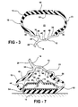
    Referring to FIGS. 1, 2 and 3, a tire 10 is mounted to a rim 12 of a wheel assembly, generally indicated at 14. The tire 10 includes a tread 16 and two sidewalls 18, 20. The interior of the tire 10 includes an interior carcass surface 22. The interior carcass surface 22 is the surface that is interior of the tire 10 and opposite the tread 16. More specifically, the tread 16 and the interior contour or surface 22 are opposite sides of the same wall or surface of the tire 10. Together, the interior carcass surface 22, the sidewalls 18, 20 and the rim 12 define an interior space 23 of the tire 10.
    Each of the sidewalls 18, 20 includes a tire bead 24, 26. The tire beads 24, 26 extend around the entire inner diameter of the tire 10. Although not shown, the tire beads 24, 26 include a coil of wires extending therethrough. The coils cannot be stretched and, therefore, inhibit the tire 10 from becoming wider, under pressure, than the flanges of the rim 12.
    The wheel assembly 14 includes a disk 28. The disk 28 defines a hub receiving center 30. The hub receiving center 30 is mounted to a hub of a motor vehicle (neither shown). The hub receiving center 30 typically includes a plurality of holes 32 that extend therethrough for receiving lug studs and/or lug nuts to secure the wheel assembly 14 to the hub of the motor vehicle.
    The disk 28 extends out to an outer peripheral edge 34. As may be appreciated by those skilled in the art, the outer peripheral edge 34 is circular in design.
    The rim 12 is fixedly secured to the outer peripheral edge 34. The rim 12 and the disk 28 may be manufactured as a unitary structure, as in the construction of an aluminum wheel (FIG. 3). The rim 12 and disk 28 may be disparate pieces joined together via a well known welding procedure and the like, according to the metal used for the manufacture of the wheel. This is the standard steel wheel construction, as is shown in FIG. 2.
    The rim 12 includes first 36 and second 38 tire seat surfaces. The tire seat surfaces 36, 38 extend generally perpendicular to the disk 28. The tire beads 24, 26 abut and engage the tire seat surfaces 36, 38 when the tire 10 is inflated on the wheel assembly 14. In the Figures 2 and 3 the tire seat surfaces 36, 38 extend through respective planes that are approximately five degrees off with respect to the surface upon which the tire 10 is being rotated.
    A wheel well, generally indicated at 40, separates the two tire seat surfaces 36, 38. The wheel well 40 is defined by a bottom surface 42 and two side surfaces 44, 46. The bottom surface 42 is the structure that is fixedly secured to the outer peripheral edge 34 of the disk 28. The wheel well 40 is designed to allow the tire beads 24, 26 to temporarily rest therein while the portion of the tire beads 24, 26 diametrically opposite may be slid over the rim 12 to be secured thereto. Therefore, the wheel well 40 is the structure in the wheel assembly 14 that allows the wheel assembly 14 to be a unitary structure having no removable parts. In other words, the wheel assembly 14 is a single structure because the wheel well 40 allows the tire 10 to be mounted thereto without having to change, alter or compromise the profile of the wheel assembly 14.
    The rim 12 of the wheel assembly 14 also includes first 48 and second 50 rim flanges. The first 48 and second 50 rim flanges are fixedly secured to the first 36 and second 38 tire seat surfaces, respectively. The rim flanges 48, 50 receive a portion of the sidewalls 18, 20 disposed adjacent the tire beads 24, 26. The rim flanges 48, 50 extend out from the tire seat surfaces 36, 38 at an angle less than or equal to thirty degrees. In the preferred embodiments shown in the Figures, the angle between the rim flanges 48, 50 and the tire seat surfaces 36, 38 is within the range of twenty and thirty degrees and preferably twenty-five degrees, with respect to a horizontal plane. The angle depends, however, on the carcass line (not shown in the Figures) of the tire 10. The shallowness of the rim flanges 48, 50 improves the vertical elasticity of the tires 10 featuring low aspect ratios while enhancing the overall performance of the tire 10, even those tires 10 with the low aspect ratios.
    As discussed above, the rim 12, including the tire seat surfaces 36, 38 and the rim flanges 48, 50 form a unitary structure, which creates strength in the wheel assembly 14.
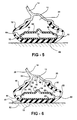
    Referring now to FIGS. 4 through 7, a run flat device is generally indicated at 62. In geometric terms, the run flat device 62 is designed to provide support to the tread 16 of the tire 10 should the tire 10 lose pressure to a non-operational level, i.e., flat. In mechanical terms, the run flat device 62 protects the sidewalls 18, 20 from collapsing. As should be appreciated by those skilled in the art, a tire 10 that is operated in a flat situation is eventually destroyed due to the stresses, strains and friction applied to the sidewalls 18, 20 that have collapsed onto each other and are pinched between the rim flanges 48, 50 and the road.
    The run flat device 62 includes an inner rim 64. The inner rim 64 extends between first 66 and second 68 ends. Each of the ends 66, 68 includes a flange 70, 72. The overall width of the inner rim 64 is determined by the geometry of the tire 10.
    The inner rim 64 also includes a channel 74. The channel 74 is designed to extend through a portion of the length of the inner rim 64 at a location in alignment with the wheel well 40 of the rim 12. The channel 74 performs two functions. First, the channel 74 strengthens the inner rim 64. Second, the channel 74 centers an inner tube 78, discussed subsequently, on the inner rim 64. In situations when the pressure inside the tire 10 has been reduced to a non-operational level, the channel 74 may engage the wheel well 40 and helps prevent the inner rim 64 from becoming misaligned with the wheel assembly 14. Alignment between the two rims 12, 64 helps maintain the tire 10 on the wheel assembly 14 in situations of flats and low pressure operation.
    A valve system 76 is mounted within the channel 74 through the inner tube 78. The valve system 76 may be a traditional valve stem. Or, in the alternative, the valve system 76 may be a cured self-sealing material that can re-seal itself after a needle has been removed therefrom.
    The run flat device 62 further includes an inner tube 78. The inner tube 78 is fabricated from the same type of material that is used to manufacture the carcass of the tire 10. The inner tube 78 is bonded to the inner rim 64 along the entire surface of the inner rim 64 extending therebetween.
    The inner tube 78 is also bonded to the interior contour or surface 22 of the tire 10. By bonding the inner tube 78 to both the interior contour or surface 22 and the inner rim 64, slippage between the inner tube 78 and the tire 10 is eliminated. When the tread 16 of a rolling tire 10 comes in contact with a driving surface, large deformations appear in the structure of the tire 10. As a consequence, relative speeds of the tire components are modified.
    As a consequence, slippages appear between components that are not firmly bonded. In fact, for a standard tire 10, the only actual slippage appears at the interface of the tread 16 and the driving surface. The resulting friction is directly responsible for the wear of the tread 16. Bonding the inner tube 78 to the tire 10 substantially reduces the wear of the inner tube 78, thus increasing the life thereof. In this situation, the integrity of the tire 10 is not compromised and the pressure within the tire 10 remains constant. If the nail 80 is long enough that it could potentially extend through the inner tube 78, especially after the inner tube 78 has lost pressure, the inner rim 64 prevents the nail 80 from penetrating further, thus protecting the integrity of the tire 10.
    Referring to FIG. 6, a channel 82 deflects a nail 83 from the tire 10. In addition, should a second nail 85 penetrate the inner tube 78, the inner rim 64 protects the interior of the tire 10from deflating by preventing the nail 85 from extending into the interior of the tire 10. In other words, the integrity of the tire 10 is maintained even though the tread 16 has taken in the nail 85.
    Should a nail 84, FIG. 7, penetrate the tire 10 and not the inner tube 78, the pressure in the inner tube 78 is maintained allowing the motor vehicle to continue operating until the tire 10 can be repaired.
    In FIG. 5, an alternative embodiment of the inner tube 78 is shown. In this embodiment, the inner tube 78 includes reinforced sidewall appliques 86. The reinforced sidewall appliques 86 provide increased resistance to puncture and avoids wobbling when the inner tube 78 is deflated.
    The invention has been described in an illustrative manner. It is to be understood that the terminology, which has been used, is intended to be in the nature of words of description rather than of limitation.
    Many modifications and variations of the invention are possible in light of the above teachings. Therefore, within the scope of the appended claims, the invention may be practiced other than as specifically described.

    Claims (7)

    1. A run flat assembly (62) for use with a wheel (30) and a pneumatic tire (10) having a tread (16), two sidewalls (18, 20) and an interior carcass surface (22), said run flat assembly (62) comprising:
      an inner tube (78) having an outer surface bonded to the interior contour (22) of the pneumatic tire (10);
      and an inner rim (64) bonded to said inner tube (78) opposite the interior contour (22), said inner rim (64) abutting a wheel rim when pressure in the pneumatic tire (10) is reduced to a non-operational level.
    2. A run flat assembly (62) as set forth in claim 1, wherein said inner rim (64) extends between first (66) and second ends (68).
    3. A run flat assembly (62) as set forth in claim 2, wherein said inner rim includes a peripheral flange (70, 72) fixedly secured to each of said first (66) and second (68) ends.
    4. A run flat assembly (62) as set forth in claim 3, wherein said inner rim (64) defines a predetermined length less than a length of the wheel.
    5. A run flat assembly (62) as set forth in claim 4 wherein said inner rim includes a channel (74) engagable with a well (40) of the wheel (30) when the pressure of the pneumatic tire is reduced to the non-operational level.
    6. A run flat assembly as set forth in claim 5 including a valve (76) disposed within said channel (74).
    7. A run flat assembly as set forth in claim 6, wherein said inner tube (78) includes secondary sidewall appliqués (86) to reinforce said inner tube (78).
    EP05103905A 2002-02-15 2003-02-14 Run flat assembly Withdrawn EP1591277A1 (en)

    Applications Claiming Priority (3)

    Application Number Priority Date Filing Date Title
    US10/077,335 US6568765B1 (en) 2002-02-15 2002-02-15 Composite wheel having a shallow rim
    US77335 2002-02-15
    EP03711076A EP1478524B1 (en) 2002-02-15 2003-02-14 Composite wheel having a shallow rim

    Related Parent Applications (2)

    Application Number Title Priority Date Filing Date
    EP03711076.4 Division 2003-02-14
    EP03711076A Division EP1478524B1 (en) 2002-02-15 2003-02-14 Composite wheel having a shallow rim

    Publications (1)

    Publication Number Publication Date
    EP1591277A1 true EP1591277A1 (en) 2005-11-02

    Family

    ID=22137457

    Family Applications (3)

    Application Number Title Priority Date Filing Date
    EP05103905A Withdrawn EP1591277A1 (en) 2002-02-15 2003-02-14 Run flat assembly
    EP07105206A Withdrawn EP1800910A2 (en) 2002-02-15 2003-02-14 Run flat assembly
    EP03711076A Expired - Lifetime EP1478524B1 (en) 2002-02-15 2003-02-14 Composite wheel having a shallow rim

    Family Applications After (2)

    Application Number Title Priority Date Filing Date
    EP07105206A Withdrawn EP1800910A2 (en) 2002-02-15 2003-02-14 Run flat assembly
    EP03711076A Expired - Lifetime EP1478524B1 (en) 2002-02-15 2003-02-14 Composite wheel having a shallow rim

    Country Status (11)

    Country Link
    US (1) US6568765B1 (en)
    EP (3) EP1591277A1 (en)
    JP (1) JP2005534548A (en)
    CN (1) CN1642760A (en)
    AT (1) ATE362849T1 (en)
    AU (1) AU2003215260A1 (en)
    BR (1) BR0307812A (en)
    CA (1) CA2476300A1 (en)
    DE (1) DE60313953D1 (en)
    MX (1) MXPA04007904A (en)
    WO (1) WO2003070494A1 (en)

    Families Citing this family (5)

    * Cited by examiner, † Cited by third party
    Publication number Priority date Publication date Assignee Title
    US7270382B2 (en) * 2003-10-21 2007-09-18 Hodges Frank J Wheel with increased interior lip depth
    KR20110102307A (en) * 2008-11-28 2011-09-16 스미토모 고무 고교 가부시키가이샤 Wheel rims for tires
    US20110018335A1 (en) * 2009-07-21 2011-01-27 Hodges Frank J Wheel component covering
    US8919890B2 (en) * 2009-11-02 2014-12-30 Segiu Anca Wheel with increased interior lip depth
    CN103231628B (en) * 2013-05-21 2015-10-28 张国法 Vacuum tyre tire-burst safety device

    Citations (5)

    * Cited by examiner, † Cited by third party
    Publication number Priority date Publication date Assignee Title
    US4143697A (en) * 1977-02-10 1979-03-13 Uniroyal Inner tube assembly for run-flat tires
    US5035273A (en) * 1987-09-21 1991-07-30 Francesco Ruvio Vehicle wheel rim device for mounting a first tire casing inwardly of a second tire casing, providing a safety emergency wheel device
    WO1992008621A1 (en) * 1990-11-08 1992-05-29 Lambe Donald M Dual chamber pneumatic tire
    DE4317268A1 (en) * 1993-05-24 1994-12-01 Josef Piller Dividable rim with a mount for tyres having a covering sheath
    FR2720980A1 (en) * 1994-06-13 1995-12-15 Pierre Cantuti Tyre drivable with puncture

    Family Cites Families (20)

    * Cited by examiner, † Cited by third party
    Publication number Priority date Publication date Assignee Title
    FR600200A (en) * 1925-06-27 1926-02-01 Michelin & Cie Method of fixing automobile pneumatic tires on their rims
    US2925845A (en) * 1954-09-15 1960-02-23 Curtiss Wright Corp Tire for vehicles, composed of two concentric annular chambers
    JPS5235161B2 (en) 1973-06-21 1977-09-07
    DE2352871A1 (en) * 1973-10-22 1975-04-30 Continental Gummi Werke Ag LOCKING DEVICE FOR TIRE DEADS ON AIR TIRED VEHICLE WHEELS
    US3993114A (en) 1974-03-13 1976-11-23 Hinderks M V Pneumatic tire
    US3938573A (en) 1974-04-11 1976-02-17 The B. F. Goodrich Company Run flat tire and wheel assembly
    US4015652A (en) 1975-11-12 1977-04-05 The Goodyear Tire & Rubber Company Tire and rim assembly
    US4077455A (en) * 1976-01-05 1978-03-07 The Goodyear Tire & Rubber Company Radial ply pneumatic tire and rim assembly
    US4293017A (en) 1977-12-01 1981-10-06 Lambe Donald M Dual-chamber pneumatic tire
    US4263953A (en) 1979-01-15 1981-04-28 Uniroyal, Inc. Self-lubricating pneumatic insert for a pneumatic tire
    IN155019B (en) * 1979-12-06 1984-12-22 Dunlop Ltd
    DE3016255A1 (en) * 1980-04-26 1981-10-29 Messerschmitt-Bölkow-Blohm GmbH, 8000 München GAS FILLED VEHICLE TIRE
    US4658876A (en) 1983-04-12 1987-04-21 The Uniroyal Goodrich Tire Company Automotive vehicle tire and mounting system therefor
    WO1987006889A1 (en) * 1986-05-15 1987-11-19 Sumitomo Rubber Industries, Ltd. Wheel rim and assembly of wheel rim and tire
    GB8702889D0 (en) 1987-02-10 1987-03-18 Sp Tyres Uk Ltd Wheel rim
    US5176764A (en) * 1991-05-08 1993-01-05 The Goodyear Tire & Rubber Company Tire assembly with inner and outer tires having cooperating vent components
    US5599409A (en) 1995-07-14 1997-02-04 Bridgestone/Firestone, Inc. Radial tire/wheel assembly for high brake heat generated service
    SE508526C2 (en) * 1997-02-12 1998-10-12 Saab Automobile Method and apparatus for sound attenuation in wheels
    FR2772666B1 (en) * 1997-12-19 2000-01-21 Michelin & Cie TREAD SUPPORT MEMBRANE
    DE60004312T2 (en) * 1999-12-09 2004-06-17 Société de Technologie Michelin Commercial vehicle wheel with a valve opening on the outside of the wheel disc

    Patent Citations (5)

    * Cited by examiner, † Cited by third party
    Publication number Priority date Publication date Assignee Title
    US4143697A (en) * 1977-02-10 1979-03-13 Uniroyal Inner tube assembly for run-flat tires
    US5035273A (en) * 1987-09-21 1991-07-30 Francesco Ruvio Vehicle wheel rim device for mounting a first tire casing inwardly of a second tire casing, providing a safety emergency wheel device
    WO1992008621A1 (en) * 1990-11-08 1992-05-29 Lambe Donald M Dual chamber pneumatic tire
    DE4317268A1 (en) * 1993-05-24 1994-12-01 Josef Piller Dividable rim with a mount for tyres having a covering sheath
    FR2720980A1 (en) * 1994-06-13 1995-12-15 Pierre Cantuti Tyre drivable with puncture

    Also Published As

    Publication number Publication date
    JP2005534548A (en) 2005-11-17
    MXPA04007904A (en) 2005-04-19
    ATE362849T1 (en) 2007-06-15
    WO2003070494A1 (en) 2003-08-28
    CA2476300A1 (en) 2003-08-28
    US6568765B1 (en) 2003-05-27
    AU2003215260A1 (en) 2003-09-09
    EP1478524B1 (en) 2007-05-23
    EP1800910A2 (en) 2007-06-27
    EP1478524A1 (en) 2004-11-24
    CN1642760A (en) 2005-07-20
    DE60313953D1 (en) 2007-07-05
    BR0307812A (en) 2005-08-16

    Similar Documents

    Publication Publication Date Title
    US5971047A (en) Tire having beads of specified structure and assembly of rim and bearing support with same
    KR100303666B1 (en) Vulcanized Radial Fly Air Tire
    EP4212355B1 (en) Pneumatic tire
    US20180319228A1 (en) Wheel for an air maintenance tire system
    US6609549B2 (en) Assembly consisting of a rim and a bearing support
    US10821784B2 (en) Vehicle tyre with enhanced bead contour
    EP1591277A1 (en) Run flat assembly
    KR20130133813A (en) Vehicle wheel for commercial vehicles
    JP3910679B2 (en) Low pressure all-terrain vehicle pneumatic tire and rim assembly
    US4732198A (en) Vehicle wheel
    EP1260388B1 (en) Pneumatic tire
    JP4430826B2 (en) Tire and rim assembly
    JPH06219111A (en) Radial tires for heavy loads
    US6457501B1 (en) Tire and rim assembly
    JP2007168544A (en) Pneumatic tire
    JPH1024713A5 (en)
    US20130033095A1 (en) Wheel and Multi Chamber Tire Assembly
    US20080210357A1 (en) Vehicle Wheel Rim Designed For Mounting A Tyre And A Support
    JP2007106259A (en) Rim
    CN108058550B (en) Air maintenance tire
    US4922983A (en) Vehicle wheel and tire assembly
    EP4711155A1 (en) Heavy duty tire
    US3674080A (en) Wheel for high-speed cornering
    EP1466760A1 (en) Tire support ring reinforcement
    WO2004022361A2 (en) Wheel with safety support for tubeless tyres

    Legal Events

    Date Code Title Description
    PUAI Public reference made under article 153(3) epc to a published international application that has entered the european phase

    Free format text: ORIGINAL CODE: 0009012

    AC Divisional application: reference to earlier application

    Ref document number: 1478524

    Country of ref document: EP

    Kind code of ref document: P

    AK Designated contracting states

    Kind code of ref document: A1

    Designated state(s): AT BE BG CH CY CZ DE DK EE ES FI FR GB GR HU IE IT LI LU MC NL PT SE SI SK TR

    AKX Designation fees paid
    STAA Information on the status of an ep patent application or granted ep patent

    Free format text: STATUS: THE APPLICATION IS DEEMED TO BE WITHDRAWN

    18D Application deemed to be withdrawn

    Effective date: 20060503

    REG Reference to a national code

    Ref country code: DE

    Ref legal event code: 8566