EP1589633A2 - Insulated motor core and method for producing same - Google Patents
Insulated motor core and method for producing same Download PDFInfo
- Publication number
- EP1589633A2 EP1589633A2 EP05447085A EP05447085A EP1589633A2 EP 1589633 A2 EP1589633 A2 EP 1589633A2 EP 05447085 A EP05447085 A EP 05447085A EP 05447085 A EP05447085 A EP 05447085A EP 1589633 A2 EP1589633 A2 EP 1589633A2
- Authority
- EP
- European Patent Office
- Prior art keywords
- spray
- coated
- insulating film
- core
- film
- Prior art date
- Legal status (The legal status is an assumption and is not a legal conclusion. Google has not performed a legal analysis and makes no representation as to the accuracy of the status listed.)
- Withdrawn
Links
- 238000004519 manufacturing process Methods 0.000 title description 7
- 239000007921 spray Substances 0.000 claims abstract description 200
- 238000000576 coating method Methods 0.000 claims abstract description 140
- 239000011248 coating agent Substances 0.000 claims abstract description 126
- 238000000034 method Methods 0.000 claims abstract description 77
- 239000003973 paint Substances 0.000 claims description 84
- 238000004070 electrodeposition Methods 0.000 claims description 65
- 238000005507 spraying Methods 0.000 claims description 56
- 229920005989 resin Polymers 0.000 claims description 33
- 239000011347 resin Substances 0.000 claims description 33
- 239000002184 metal Substances 0.000 claims description 28
- 229910052751 metal Inorganic materials 0.000 claims description 28
- BPQQTUXANYXVAA-UHFFFAOYSA-N Orthosilicate Chemical compound [O-][Si]([O-])([O-])[O-] BPQQTUXANYXVAA-UHFFFAOYSA-N 0.000 claims description 21
- 238000010438 heat treatment Methods 0.000 claims description 19
- 239000004593 Epoxy Substances 0.000 claims description 14
- 125000002091 cationic group Chemical group 0.000 claims description 14
- 125000000129 anionic group Chemical group 0.000 claims description 11
- ATJFFYVFTNAWJD-UHFFFAOYSA-N Tin Chemical compound [Sn] ATJFFYVFTNAWJD-UHFFFAOYSA-N 0.000 claims description 10
- RMAQACBXLXPBSY-UHFFFAOYSA-N silicic acid Chemical compound O[Si](O)(O)O RMAQACBXLXPBSY-UHFFFAOYSA-N 0.000 claims description 8
- 229910052710 silicon Inorganic materials 0.000 claims description 8
- 239000010703 silicon Substances 0.000 claims description 8
- 235000012239 silicon dioxide Nutrition 0.000 claims description 8
- 238000009413 insulation Methods 0.000 abstract description 69
- 239000010410 layer Substances 0.000 description 71
- LRHPLDYGYMQRHN-UHFFFAOYSA-N N-Butanol Chemical compound CCCCO LRHPLDYGYMQRHN-UHFFFAOYSA-N 0.000 description 45
- KFZMGEQAYNKOFK-UHFFFAOYSA-N Isopropanol Chemical compound CC(C)O KFZMGEQAYNKOFK-UHFFFAOYSA-N 0.000 description 36
- YXFVVABEGXRONW-UHFFFAOYSA-N Toluene Chemical compound CC1=CC=CC=C1 YXFVVABEGXRONW-UHFFFAOYSA-N 0.000 description 21
- JHIVVAPYMSGYDF-UHFFFAOYSA-N cyclohexanone Chemical compound O=C1CCCCC1 JHIVVAPYMSGYDF-UHFFFAOYSA-N 0.000 description 20
- 238000001035 drying Methods 0.000 description 16
- YNQLUTRBYVCPMQ-UHFFFAOYSA-N Ethylbenzene Chemical compound CCC1=CC=CC=C1 YNQLUTRBYVCPMQ-UHFFFAOYSA-N 0.000 description 14
- 239000003822 epoxy resin Substances 0.000 description 14
- 239000002075 main ingredient Substances 0.000 description 14
- 229920000647 polyepoxide Polymers 0.000 description 14
- 238000004804 winding Methods 0.000 description 13
- 239000002904 solvent Substances 0.000 description 11
- 239000000047 product Substances 0.000 description 10
- ZWEHNKRNPOVVGH-UHFFFAOYSA-N 2-Butanone Chemical compound CCC(C)=O ZWEHNKRNPOVVGH-UHFFFAOYSA-N 0.000 description 9
- WSFSSNUMVMOOMR-UHFFFAOYSA-N Formaldehyde Chemical compound O=C WSFSSNUMVMOOMR-UHFFFAOYSA-N 0.000 description 9
- 239000000463 material Substances 0.000 description 9
- 238000000691 measurement method Methods 0.000 description 9
- POAOYUHQDCAZBD-UHFFFAOYSA-N 2-butoxyethanol Chemical compound CCCCOCCO POAOYUHQDCAZBD-UHFFFAOYSA-N 0.000 description 8
- SWXVUIWOUIDPGS-UHFFFAOYSA-N diacetone alcohol Chemical compound CC(=O)CC(C)(C)O SWXVUIWOUIDPGS-UHFFFAOYSA-N 0.000 description 8
- 239000000203 mixture Substances 0.000 description 8
- CTQNGGLPUBDAKN-UHFFFAOYSA-N O-Xylene Chemical compound CC1=CC=CC=C1C CTQNGGLPUBDAKN-UHFFFAOYSA-N 0.000 description 7
- 239000008096 xylene Substances 0.000 description 7
- QTBSBXVTEAMEQO-UHFFFAOYSA-M Acetate Chemical compound CC([O-])=O QTBSBXVTEAMEQO-UHFFFAOYSA-M 0.000 description 6
- 239000002253 acid Substances 0.000 description 6
- 239000011247 coating layer Substances 0.000 description 5
- 238000002360 preparation method Methods 0.000 description 5
- 239000004925 Acrylic resin Substances 0.000 description 4
- 229920000178 Acrylic resin Polymers 0.000 description 4
- DKPFZGUDAPQIHT-UHFFFAOYSA-N Butyl acetate Natural products CCCCOC(C)=O DKPFZGUDAPQIHT-UHFFFAOYSA-N 0.000 description 4
- NTIZESTWPVYFNL-UHFFFAOYSA-N Methyl isobutyl ketone Chemical compound CC(C)CC(C)=O NTIZESTWPVYFNL-UHFFFAOYSA-N 0.000 description 4
- UIHCLUNTQKBZGK-UHFFFAOYSA-N Methyl isobutyl ketone Natural products CCC(C)C(C)=O UIHCLUNTQKBZGK-UHFFFAOYSA-N 0.000 description 4
- 230000015572 biosynthetic process Effects 0.000 description 4
- 230000007797 corrosion Effects 0.000 description 4
- 238000005260 corrosion Methods 0.000 description 4
- 125000004494 ethyl ester group Chemical group 0.000 description 4
- FUZZWVXGSFPDMH-UHFFFAOYSA-N hexanoic acid Chemical compound CCCCCC(O)=O FUZZWVXGSFPDMH-UHFFFAOYSA-N 0.000 description 4
- JEIPFZHSYJVQDO-UHFFFAOYSA-N iron(III) oxide Inorganic materials O=[Fe]O[Fe]=O JEIPFZHSYJVQDO-UHFFFAOYSA-N 0.000 description 4
- 229940043265 methyl isobutyl ketone Drugs 0.000 description 4
- 238000009877 rendering Methods 0.000 description 4
- 239000000454 talc Substances 0.000 description 4
- 229910052623 talc Inorganic materials 0.000 description 4
- XLYOFNOQVPJJNP-UHFFFAOYSA-N water Substances O XLYOFNOQVPJJNP-UHFFFAOYSA-N 0.000 description 4
- LRXTYHSAJDENHV-UHFFFAOYSA-H zinc phosphate Chemical compound [Zn+2].[Zn+2].[Zn+2].[O-]P([O-])([O-])=O.[O-]P([O-])([O-])=O LRXTYHSAJDENHV-UHFFFAOYSA-H 0.000 description 4
- 229910000165 zinc phosphate Inorganic materials 0.000 description 4
- 229910000976 Electrical steel Inorganic materials 0.000 description 3
- DNIAPMSPPWPWGF-UHFFFAOYSA-N Propylene glycol Chemical compound CC(O)CO DNIAPMSPPWPWGF-UHFFFAOYSA-N 0.000 description 3
- 239000003795 chemical substances by application Substances 0.000 description 3
- 230000007812 deficiency Effects 0.000 description 3
- 238000007654 immersion Methods 0.000 description 3
- 125000000959 isobutyl group Chemical group [H]C([H])([H])C([H])(C([H])([H])[H])C([H])([H])* 0.000 description 3
- 230000002265 prevention Effects 0.000 description 3
- 125000002924 primary amino group Chemical group [H]N([H])* 0.000 description 3
- LLHKCFNBLRBOGN-UHFFFAOYSA-N propylene glycol methyl ether acetate Chemical compound COCC(C)OC(C)=O LLHKCFNBLRBOGN-UHFFFAOYSA-N 0.000 description 3
- 229910001220 stainless steel Inorganic materials 0.000 description 3
- 239000010935 stainless steel Substances 0.000 description 3
- -1 acryl Chemical group 0.000 description 2
- 239000000654 additive Substances 0.000 description 2
- 230000000996 additive effect Effects 0.000 description 2
- 150000002148 esters Chemical class 0.000 description 2
- 238000001704 evaporation Methods 0.000 description 2
- 230000008020 evaporation Effects 0.000 description 2
- 125000000524 functional group Chemical group 0.000 description 2
- LNEPOXFFQSENCJ-UHFFFAOYSA-N haloperidol Chemical compound C1CC(O)(C=2C=CC(Cl)=CC=2)CCN1CCCC(=O)C1=CC=C(F)C=C1 LNEPOXFFQSENCJ-UHFFFAOYSA-N 0.000 description 2
- 238000010422 painting Methods 0.000 description 2
- 229920000768 polyamine Polymers 0.000 description 2
- 230000008569 process Effects 0.000 description 2
- 238000007592 spray painting technique Methods 0.000 description 2
- 229920002675 Polyoxyl Polymers 0.000 description 1
- XUIMIQQOPSSXEZ-UHFFFAOYSA-N Silicon Chemical compound [Si] XUIMIQQOPSSXEZ-UHFFFAOYSA-N 0.000 description 1
- 229910000831 Steel Inorganic materials 0.000 description 1
- TUVYSBJZBYRDHP-UHFFFAOYSA-N acetic acid;methoxymethane Chemical compound COC.CC(O)=O TUVYSBJZBYRDHP-UHFFFAOYSA-N 0.000 description 1
- 230000002411 adverse Effects 0.000 description 1
- 150000003973 alkyl amines Chemical class 0.000 description 1
- 229910052782 aluminium Inorganic materials 0.000 description 1
- XAGFODPZIPBFFR-UHFFFAOYSA-N aluminium Chemical compound [Al] XAGFODPZIPBFFR-UHFFFAOYSA-N 0.000 description 1
- 125000003277 amino group Chemical group 0.000 description 1
- 230000003466 anti-cipated effect Effects 0.000 description 1
- 239000006229 carbon black Substances 0.000 description 1
- 150000001768 cations Chemical class 0.000 description 1
- 239000007795 chemical reaction product Substances 0.000 description 1
- 238000010276 construction Methods 0.000 description 1
- 229920001577 copolymer Polymers 0.000 description 1
- 230000006378 damage Effects 0.000 description 1
- 230000007547 defect Effects 0.000 description 1
- 230000000694 effects Effects 0.000 description 1
- 239000007888 film coating Substances 0.000 description 1
- 238000009501 film coating Methods 0.000 description 1
- 125000002887 hydroxy group Chemical group [H]O* 0.000 description 1
- 239000004615 ingredient Substances 0.000 description 1
- GJRQTCIYDGXPES-UHFFFAOYSA-N isobutyl acetate Chemical compound CC(C)COC(C)=O GJRQTCIYDGXPES-UHFFFAOYSA-N 0.000 description 1
- 239000007788 liquid Substances 0.000 description 1
- 238000005259 measurement Methods 0.000 description 1
- WSFSSNUMVMOOMR-NJFSPNSNSA-N methanone Chemical compound O=[14CH2] WSFSSNUMVMOOMR-NJFSPNSNSA-N 0.000 description 1
- 238000001000 micrograph Methods 0.000 description 1
- 238000012986 modification Methods 0.000 description 1
- 230000004048 modification Effects 0.000 description 1
- 239000000178 monomer Substances 0.000 description 1
- 229910001172 neodymium magnet Inorganic materials 0.000 description 1
- 229920000620 organic polymer Polymers 0.000 description 1
- 230000002093 peripheral effect Effects 0.000 description 1
- 239000000049 pigment Substances 0.000 description 1
- 239000004033 plastic Substances 0.000 description 1
- 229920003023 plastic Polymers 0.000 description 1
- 229920006122 polyamide resin Polymers 0.000 description 1
- 229920001225 polyester resin Polymers 0.000 description 1
- 239000004645 polyester resin Substances 0.000 description 1
- 229920001228 polyisocyanate Polymers 0.000 description 1
- 239000005056 polyisocyanate Substances 0.000 description 1
- 229920000642 polymer Polymers 0.000 description 1
- 229920005862 polyol Polymers 0.000 description 1
- 150000003077 polyols Chemical class 0.000 description 1
- 239000000843 powder Substances 0.000 description 1
- 230000003449 preventive effect Effects 0.000 description 1
- 230000009467 reduction Effects 0.000 description 1
- 230000003014 reinforcing effect Effects 0.000 description 1
- 150000003376 silicon Chemical class 0.000 description 1
- 238000002791 soaking Methods 0.000 description 1
- 239000011877 solvent mixture Substances 0.000 description 1
- 239000010959 steel Substances 0.000 description 1
- 239000000126 substance Substances 0.000 description 1
- 239000000758 substrate Substances 0.000 description 1
- 229920002803 thermoplastic polyurethane Polymers 0.000 description 1
- 230000008719 thickening Effects 0.000 description 1
- 125000000391 vinyl group Chemical group [H]C([*])=C([H])[H] 0.000 description 1
- 229920002554 vinyl polymer Polymers 0.000 description 1
Images
Classifications
-
- H—ELECTRICITY
- H02—GENERATION; CONVERSION OR DISTRIBUTION OF ELECTRIC POWER
- H02K—DYNAMO-ELECTRIC MACHINES
- H02K1/00—Details of the magnetic circuit
- H02K1/04—Details of the magnetic circuit characterised by the material used for insulating the magnetic circuit or parts thereof
-
- Y—GENERAL TAGGING OF NEW TECHNOLOGICAL DEVELOPMENTS; GENERAL TAGGING OF CROSS-SECTIONAL TECHNOLOGIES SPANNING OVER SEVERAL SECTIONS OF THE IPC; TECHNICAL SUBJECTS COVERED BY FORMER USPC CROSS-REFERENCE ART COLLECTIONS [XRACs] AND DIGESTS
- Y10—TECHNICAL SUBJECTS COVERED BY FORMER USPC
- Y10T—TECHNICAL SUBJECTS COVERED BY FORMER US CLASSIFICATION
- Y10T29/00—Metal working
- Y10T29/49—Method of mechanical manufacture
- Y10T29/49002—Electrical device making
- Y10T29/49009—Dynamoelectric machine
Definitions
- the present invention relates to an insulated motor core. More specifically, it relates to a motor core coated with a multi-layer insulating film and to methods for producing the insulated core.
- the performance of small motor cores is significantly affected by the thickness of the insulation film. That is, as the thickness is increased, the film-coated area of the winding becomes smaller, thereby making it necessary to restrict the number of windings. Even if the same number of windings may be used, the total length of the windings becomes greater, thereby adversely affecting the efficiency of the motor and making it difficult to reduce the size of the motor as a whole.
- Toku Kai Hei 8-265994 discloses a core having an electrodeposited film, which does not provide satisfactory insulation, produced by electrodeposition upon a core for a motor that drives a magnetic memory medium such as a hard disk.
- the problems with the coating are attributable to thickening of the coating along the edge of the core.
- the tin (Sn) component of the aqueous coating solution used in the electrodeposition coating process is present in an amount of less than 12 ppm. As the amount is increased, the coating becomes thicker. The amount of carbon black is set at less than 0.5 weight per cent.
- An insulation film is electrodeposited to a prescribed thickness on the parts of the motor (i.e., the plastic magnet of the Nd-Fe-B system, the core made of silicon steel, and the motor base formed of die-cast aluminum) by means of cation electrodeposition coating employing an electrodeposition paint which was prepared by adding T i02 and/or Si02 to the paint.
- the painted parts are heated to between 40 and 120 degrees centigrade, following which a second-stage hardening treatment is carried out wherein the parts are heated to between 150 and 190 degrees centigrade.
- the reference discloses that in a hard-disk drive device prepared by assembling the coated parts, there is no scattering of the tin and no destruction of the memory. A disc drive device having satisfactory corrosion resistance and insulation properties is thus obtained.
- Insulating films formed via electrodeposition coating are characterized in that, as opposed to those formed by spray coating, an electrodeposited film can be formed everywhere upon the surface of a device, including the corners, no matter how complicated the shape involved may be. Electrodeposited coatings are further characterized in that the insulation film may have a minimal thickness, thereby rendering the technique advantageous from the standpoint of permitting a reduction in size of the coated part. Nevertheless, even with the use of electrodeposition coating techniques, it is difficult to ensure that the thickness of the coated film at an angular portion of the coated device is the same as the thickness of the film on the planar portions thereof, thus rendering it substantially inevitable that the film at the aforementioned angular portions will be thinner than that on the planar portions.
- the reduced thickness of the film at such angular portions results in incursion of the winding whereupon the winding comes into contact with an uninsulated portion of the part, thereby leading to an insulation failure. Furthermore, the reduced thickness of the electrodeposited film at such angular portions often permits rusting of the coated part.
- the Pressure-Resistance test is well-known among those of ordinary skill in this art as a means of measuring resistance to passage of a current, also referred to herein as "pressure resistance” or “electrical pressure resistance", through a coated object.
- the test is performed by connecting electrical leads to a coated and an uncoated surface, respectively, of an object, such as a motor core, and passing an alternating current (AC), e.g., measuring 100, 200 and/or 500 volts (V) between the leads.
- AC alternating current
- V 500 volts
- the present invention is directed to a motor core wherein the above-described problems have been solved. That is, in an example embodiment, the invention relates to a core with an insulating coating that is thin and has satisfactory rust-preventive and insulation properties, that does not lead to problems in connection with the winding of the slot of the motor core, and that is suitable for use in the preparation of a small-sized precision motor of high efficiency.
- the motor core of the invention in which, as described below, an electrodeposition coating is provided mainly for the purpose of rust prevention.
- the insulating film coating includes a multi-layer laminated structure having: an electrodeposited layer, a comparatively soft insulation layer whose purpose is to form a uniform film and to allow production of a desired film thickness on angular portions of the coated substrate, and a relatively harder insulation layer adapted to prevent incursion due to tension at the time of winding.
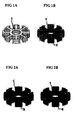
- Fig. 1a illustrates an uncoated motor core.
- Fig. 1b illustrates the motor core coated with an electrodeposited film according to the invention;
- Fig. 2a illustrates the electrodeposition-coated core of Fig. 1b further provided with a first spray coated film.
- Fig. 2b illustrates the first-spray coated core of Fig. 2a additionally coated with a second spray coated film;
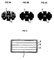
- Figure 3 illustrates the progression by which a core coated on a first surface with an electrodeposition coating, a first spray coated film and a second spray coated film is thereafter coated, on a second opposed surface with an electrodeposited film (3a), followed by a first spray coated film (3b) and then a second spray coated film (3c);
- Fig. 4 illustrates a laminated coated film structure formed according to the invention as deposited upon the surface of a motor core
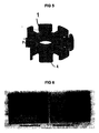
- Fig. 5 is provided for the purpose of illustrating the location of P1 (Position 1) where the photomicrographs of Figs. 6 and 7 were taken;
- Fig. 6 is a photograph presenting a cross-sectional view, at position1 of the film-coated core according to the invention.
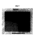
- Fig. 7 is a photograph presenting a cross sectional view along an edge portion at position 1.
- the present invention provides a motor core coated with a multi-layer insulating film, which preferably includes, in order: an electrodeposited coating film applied upon an outer surface of the motor core; a first spray-coated insulating film applied upon an outer surface of the electrodeposited coating film, the first spray-coated film having a pencil hardness of between about 2H and 4H; and a second spray-coated insulating film applied upon an outer surface of the first spray-coated insulating film, the second spray coated film having a pencil hardness of between about 3H and 6H.
- the invention further provides a motor core coated with a multi-layer insulating film wherein the insulating film preferably includes, in order: an electrodeposited coating film applied upon an outer surface of the motor core, the electrodeposited coating film having a mean thickness of between about 10 and 25 ⁇ m; a first spray-coated insulating film applied upon an outer surface of the electrodeposited coating film, the first spray-coated insulating film having a mean thickness of between about 20 and 35 ⁇ m and a pencil hardness of between about 2H and 4H; and a second spray-coated insulating film applied upon an outer surface of the first spray-coated insulating film, the second spray-coated insulating film having a mean thickness of between about 5 and 15 ⁇ m and a pencil hardness of between about 3H and 6H.
- the insulating film preferably includes, in order: an electrodeposited coating film applied upon an outer surface of the motor core, the electrodeposited coating film having a mean thickness of between about 10 and 25 ⁇ m; a first spray-coated
- the invention additionally provides a motor core coated with a multi-layer insulating film wherein the insulating film preferably includes, in order: an electrodeposited coating film applied upon an outer surface of the motor core, the electrodeposited coating film formed from an anionic or a cationic electrodeposition paint and having a mean thickness of between about 10 and 25 ⁇ m; a first spray-coated insulating film applied upon an outer surface of the electrodeposited coating film, the first spray-coated insulating film formed from an epoxy paint and having a mean thickness of between about 20 and 35 ⁇ m and a pencil hardness of between about 2H and 4H; and a second spray-coated insulating film applied upon an outer surface of the first spray-coated insulating film, the second spray-coated insulating film being formed from a paint having a denatured silicate resin obtained by reacting a silicate resin with silicic acid and having a mean thickness of between about 5 and 15 ⁇ m and a pencil hardness of between about 3H and 6H.
- the invention further provides a method for preparing a motor core coated with a multi-layer insulating film, wherein the method includes: coating a motor core having first and second opposed surfaces, with an electrodeposited coating film; applying, to an outer surface of the electrodeposited film, a first spray-coated insulating film having a pencil hardness of between about 2H and 4H; and applying, upon an outer surface of the first spray-coated insulating film, a second spray-coated insulating film having a pencil hardness of between about 3H and 6H.
- the invention also provides a method for preparing a motor core coated with a multi-layer insulating film, wherein the method includes: coating a motor core, having first and second opposed surfaces, with an electrodeposited coating film; placing the electrodeposition coated core upon a coating tool (e.g., a wire mesh); applying, to an outer portion of a first surface of the electrodeposited film, a first spray-coated insulating film having a pencil hardness of between about 2H and 4H; applying, upon an outer portion of the first spray-coated insulating film on the first core surface, a second spray-coating insulating film having a pencil hardness of between about 3H and 6H; turning the motor core over upon the coating tool so as to expose the second opposed surface thereof for further coating; applying, to an outer portion of a second surface of the electrodeposition film, a first spray-coated insulation film having a pencil hardness between about 2H and 4H; and applying, upon an outer portion of the first spray-coated insulating film on the second opposed
- the invention additionally provides a method for preparing a motor core coated with a multi-layer insulating film, wherein the method includes: coating a motor core having first and second opposed surfaces, with an electrodeposited coating film; placing the electrodeposition-coated core upon a coating tool; applying, to an outer portion of a first surface of the electrodeposited film, a first spray-coated insulating film having a pencil hardness of between about 2H and 4H; turning the core over upon the coating tool to expose the second opposed surface of the core; applying, to an outer portion of a second surface of the electrodeposited film, a first spray-coated insulating film having a pencil hardness of between about 2H and 4H; applying, upon an outer portion of the first spray-coated insulating film on the second opposed core surface, a second spray-coated insulating film having a pencil hardness of between about 3H and 6H; turning the core over on the coating tool to expose the coated first surface of the core; and applying, upon an outer portion of the first spray-coated
- the invention also provides a method for preparing a motor core coated with a multi-layer insulating film, wherein the method includes: coating a motor core having first and second opposed surfaces, with an electrodeposition coating film; placing the electrodeposition-coated core upon a coating tool; applying, to an outer portion of a first surface of the electrodeposited film, a first spray-coated insulating film having a pencil hardness of between about 2H and 4H; turning the core over on the coating tool to expose the second, opposed surface of the core; applying, to an outer portion of a second surface of the electrodeposited film, a first spray-coated insulating film having a pencil hardness of between about 2H and 4H; turning the core over upon the coating tool to expose the first surface of the core; applying, upon an outer portion of the first spray-coated insulating film on the first core surface, a second spray-coated insulating film having a pencil hardness of between about 3H and 6H; turning the core over upon the coating tool to expose the second surface of
- the invention relates to a structure including a motor core 1 having first and second opposed surfaces, coated on its entire outer surface with a multi-layer insulating film having three layers: (a) an electrodeposition coated film layer 2, (b) a first spray coated insulation film layer 3 having a pencil hardness in the range between 2H and 4H, and (c) a second spray coated insulation film layer 4 having a pencil hardness in the range between 3H and 6H, and to methods for producing such coated cores.
- the pencil hardness test is a standard Japanese test for evaluating coating hardness, wherein the hardness of a coating is determined by comparison with a standard set of grading pencils ranging from hard to soft. The test involves applying the pencils, beginning with a relatively hard pencil and working toward the softer pencils, to the coating. The first pencil which does not scratch the coating determines the pencil hardness of the coating.
- core 1 has a structure including a plurality of laminated metal plates, as shown in Figs. 1-3 and 5.
- the mean thickness of the electrodeposited film is in the range of between about 10 and 25 ⁇ m while that of the first spray coated insulation film is in the range of between about 20 and 35 ⁇ m and wherein the second spray coated insulation film has a thickness in the range of between about 5 and 15 ⁇ m.
- the second spray insulated film may be formed with a denatured silicate resin paint that is obtained by reacting the resin with silicic acid.
- the electrodeposited film may include either a cationic or an anionic electrodeposition paint.
- the first spray coated insulation film can be an epoxy paint.
- the electrodeposition coated film is substantially free of lead (Pb) and/or tin (Sn) and silicon.
- An example embodiment of the invention additionally provides a method for the preparation of a motor core coated with an insulation film having three film layers, wherein the layers each have different attributes.
- the core is first coated with an electrodeposited film layer 2.
- a first spray coating is applied to the surface of the electrodeposited film and dried to form a first spray coated insulation film 3 thereupon whose pencil hardness is in the range between 2H and 4H.
- a second spray coating insulation film 4 having a pencil hardness of between about3H and 6H is formed by applying, and then drying, a second spray coating upon the surface of the first spray coated film layer 3.
- the core is positioned on a coating tool, e.g., a metal mesh (not shown) during the coating operation.
- a first spray coating layer is applied to the first surface of the motor core with heating in the range between 180 and 200 degrees centigrade to form a first spray coated insulation film layer 3 thereupon.
- top refers to the surface of the motor core not in contact with the mesh, whereas “bottom” is used to describe the surface opposed to the top surface.
- a second spray coated insulation layer is also applied to the first surface of core 1, atop film layer 3, in the same manner as the first spray coating layer.
- the structure coated with the second spray coated insulation layer is again heated in the range between 180 and 200 degrees centigrade, thereby forming a second spray coated insulation film 4 on the first surface coated with the first spray coated insulation film 3.
- the core is preferably flipped over, i.e., placed upside down, upon the mesh such the top of the core is now on the bottom.
- the first spray coating material is then applied to the thus exposed second opposed surface of the motor core, following which the spray-coated core is heated in the range between 180 and 200 degrees centigrade, thereby producing upon the sprayed portion of the second opposed surface a coating of the first spray coated insulation film 3.
- the second spray coating is applied in the same manner atop the first film 3 and the core 1 is then heated to the range between 180 and 200 degrees centigrade, thereby forming the second spray coated insulation film 4 atop film 3 on the second opposed surface of the core 1.
- the first spray coating is applied atop the electrodeposited coating 2 from the top of the first surface of the motor core, with time left for thinner evaporation and coat leveling, thus forming the first spray coated insulation film layer 3 thereupon.
- the second spray coating is applied to the first surface in the same manner, with heating being carried out in the range between 180 and 200 degrees centigrade, thereby forming on top of first layer 3 the second spray coated insulation film layer 4.
- Core 1, now coated on its first surface is then turned upside down such that the top is now on the bottom.
- the first spray coating is then applied to the electrodeposited layer 2 on the second opposed surface of the motor core with a corresponding delay for thinner evaporation and coat leveling to form the first spray coated insulation film layer 3 thereupon.
- the second spray coating is applied to the layer 3 on the second opposed surface and then heated to the range between 180 and 200 degrees centigrade, thereby forming the second spray coated insulation film layer 4 thereupon.
- the film heating serves as a hardening treatment for converting the liquid spray composition into a film.
- the resin located at the bottom part of the coated core which touches the metal mesh is sometimes torn away. This phenomenon is referred to as "chipping" and such products are treated as having a defect.
- the methods of the present invention serve to reduce the amount of chipping which occurs during core coating.
- the reason why there is a decrease in the rate of chipping is believed to be due to the fact that the paint used to form the second spray coating has a denatured silicate resin.
- This material is different from the material used to produce the first spray coating, which previously sometimes adhered to the metal mesh.
- the coating steps used in the invention are preferably thus arranged in such a manner that the coating material which adheres to the metal mesh is covered over by a non-stick second spray coating. This has served as a means for improving the yield of acceptable product.
- Coated motor cores formed according to this invention are relatively thin and possess satisfactory insulation properties, even at angular portions of the core.
- the coating is adapted to permit even winding, with angular portions of the coil being given a satisfactory tension in the winding of the slot of the motor core, thereby offering a high rate of winding efficiency.
- the invention is suitable for use in the production of small precision motors.
- the methods described herein result in the formation of a uniform insulation coating on all areas of the motor core, including the angular-shaped portions. These methods additionally render it possible to control the amount of chipping which occurs during the baking stage, thereby increasing the productivity of the coating method.
- the material used in forming the electrodeposition coating 2 upon the surface of the core 1 may be either an anionic or a cationic electrodeposition paint.
- Any electrodeposition paint resins may be used. However, it is desirable to employ a resin selected from among epoxy resins, urethane resins, polyester resins, and polyamide resins. These resins are well known among those of ordinary skill in the chemical coating art.
- the preferred resins for use in the present invention are the epoxy resins.
- the film used for forming the electrodeposition coating should have a thickness ranging between about 10 and 25 ⁇ m on the average at the time of heating to induce film-formation.
- the mean film thickness is less than 10 ⁇ m, the pressure resistance is reduced, even though the coating is effective in forming a rust preventive film over the entire core, including the angular portions such as at the corners. Furthermore, difficulties additionally arise in connection with the insulation of the edge portions of the coated core 1.
- the mean film thickness exceeds 25 ⁇ m
- the length of time required for forming the electrodeposition coating increases.
- the coating is applied in the indicated thickness, it becomes difficult to secure a uniform film thickness throughout the coated core, including the angular portions of the core. That is, there will be an increase in the difference of the file thickness between the flat portion and the angular portions of the coated core
- the resin that is to be used to form the first spray coated insulation film layer 3, whose pencil hardness is in the range between 2H and 4H, is the same class or type of resin as that used to form the electrodeposition coating.
- the resin used in forming both the electrodeposition coating and the first spray coated insulation film layer is an epoxy resin.
- approximately 10 weight per cent of acrylic resin is added to the epoxy resin for the purpose of hardening the composition.
- the ratio between the epoxy resin and the solvent may preferably range between 15- 25: 85 - 75 by weight.
- Preferred solvents for dissolving the epoxy resin are those whose main ingredients are toluene and n-butyl alcohol.
- the epoxy paints used in the invention may additionally contain a small amount of a hardening agent, such as zinc phosphate, etc. or a constitutional pigment such as talc, etc. Additional examples of useful materials falling within the indicated classes are well known among those of ordinary skill in this art.
- the epoxy resin paint may be thinned by the addition of thinners commonly used for spray painting.
- thinners may contain, for example, xylene, ethyl benzene and cyclohexanone as the main ingredients, with the further addition of isopropyl alcohol, n-butyl alcohol, ethylene glycol, monobutyl ether, methyl isobutyl ketone and the like.
- the ratio between the paint and the thinner is that which is ordinarily used in the painting field.
- Preferred resins for use in forming the second spray coated insulation film layer 4 of this invention are those wherein the terminal functional group of the organic polymer and the terminal functional group of an inorganic bridging agent are reacted with each other, thereby producing a bridged polymer that has both flexibility and hardness.
- a paint that is capable of forming a hard film when reacted with silicic acid.
- paints which may be used in the invention for forming the second spray coated insulation film layer 4 include paints having denatured silicate resins.
- Suitable solvents for use with paints for forming the layer 4 may include isopropyl alcohol, diacetone alcohol, cyclohexanone and ethylene glycol monobutyl ether as the main ingredients. These solvent compositions may further include materials such as n-butyl alcohol, butyl acetate and formaldehyde. Paints for use in the coating process of the invention are prepared as described above, including the addition of a thinner so as to form a thinned spray paint.
- Useful thinners may include xylene and ethyl benzene as the main ingredients, with additive materials such as ethyl ester acetate, n-butyl alcohol, toluene and acetic acid isobutyl ester, etc. added thereto. The ratio between the paint and the thinner is in the range which is ordinarily used in the spray-painting field.
- This example describes the preparation of a motor core having a multi-layer insulating film structure thereupon by means of the painting method as described above.
- the core is turned upside down to expose the second opposed surface subsequent to the hardening of the first and second spray coated films applied upon the first surface of the core.
- a core 1 having a plurality of silicate steel plates was electrodeposition coated using a paint having a denatured amino epoxy resin as a vehicle. Since this paint has cationic properties, a 200 volt direct current voltage was passed between the core 1 as a cathode and the container as an anode. The temperature of the paint solution was in the range of 25-28 degrees centigrade, with the immersion time being two minutes. The coated core was placed in a drying furnace, supported by an electrode.
- hardening is the process by which the film is formed from the spray-painted coating.
- the core was found to be coated on its entire surface with a 20 ⁇ m electrodeposited film 2 having a mean film thickness of 20 ⁇ m, using measurements taken at three points on the core (i.e., referred to herein as the three-point [or triple point] measurement method)
- a plurality of cores coated with an electrodeposited film 2 whose mean film thickness was 20 ⁇ m were arranged on a metal mesh.
- the first spray coating was applied upon the entire upper surfaces of the cores.
- the first spray coating included paint prepared as follows: an epoxy paint including 19.6 weight percent of epoxy resin, 1.9 weight per cent of acrylic resin, 71.3 weight percent of a solvent whose ingredients were toluene, n-butyl alcohol, methyl ethyl ketone and cyclohexanone, with the addition of isopropyl alcohol, and propylene glycol monomethyl ether acetate, 4.1 weight per cent of talc and 3.1 weight per cent of zinc phosphate, was thinned with a thinner whose main components were diluted by a factor of 1.2 times its original volume with xylene, ethyl benzene and cyclohexanone, and which further included isopropyl alcohol, n-butyl alcohol, ethylene glycol monobutyl ether and methyl-isobutyl ketone.
- the coated core was placed in a drying furnace. After a preliminary heating step at a temperature in the range between 40 and 120 degrees centigrade, the first spray coating layer was hardened into a film at a temperature in the range between 180 and 200 degrees centigrade for a period of approximately 20 minutes. Thus, a first spray coated insulation film layer 3 was formed on the first surface of the electrodeposited layer 2. Film 3 had a mean film thickness of 30 ⁇ m as measured by the triple-point measurement method. The pencil hardness of the first spray coated film was in the range between 2H and 4H. (see Figure 1.)
- the core was turned upside down on the metal mesh and the second opposed surface of the core was given a spray coating with the first spray paint.
- the spray painted core was then placed in a drying furnace. After a preliminary heating treatment in the range between 40 and 120 degrees centigrade, it was heated for approximately 20 minutes in the range between 180 and 200 degrees centigrade to permit hardening of the first spray paint coating. As a result of this treatment, a first spray film 3 whose average film thickness was 30 ⁇ m as measured by the triple-point measurement method was formed upon the second opposed surface.
- the pencil hardness of the first spray coated film 3 was in the range between 2H and 4H.
- the core 1 on which the first spray coated film 3 having a mean film thickness of 30 ⁇ m was formed was then coated on its second surface with the second spray coating while the core 1 was supported on a metal mesh.
- the second spray paint was prepared as set forth below.
- the coated product was heated in a drying furnace at a temperature in the range between 180 and 200 degrees centigrade for a period of about 20 minutes to harden the coating into a film.
- the heating thus produced a second spray coated insulation film layer 4 on the second surface having a mean thickness in the range between 7 and 10 ⁇ m as measured by the three-point measurement method.
- the pencil hardness of the second spray coated film 4 was greater than 4H. (see Figure 2.)
- the coated 4 core was turned over on the metal mesh and the second spray coating was applied to the first film 3 on the first surface of the core.
- the spray coated core was thereafter placed in a drying furnace and heating was carried out in the range between 180 and 200 degrees centigrade for a period of about 20 minutes to form the second spray coated insulation film layer 4 on the first surface.
- the pencil hardness of the second spray coated film 4 was greater than 4H.
- the core produced as described above was thus coated on both its first and second opposed surfaces with, in order, an electrodeposited film 2; a first spray coated insulation film layer 3; and a second spray coated insulation film layer 4.
- Application of this multi-layer insulating coating provided a core having advantageous properties as described above.
- This example relates to the preparation of a motor core having a triple-layer insulation coated film structure by a coating method wherein the core is turned over to expose its opposite surface subsequent to the initial first spray coated film hardening, then again after the second first spray coated film hardening and once again after the first second spray coated film hardening.
- the electrodeposition was carried out on a core 1 formed of a plurality of silicon steel plates. It was performed using a paint (having a Pb content less than 25 ppm and a Sn content less than 10 ppm) having a denatured amino epoxy resin as a vehicle.
- the paint was cationic and thus a direct current of 200 volts was passed between the core serving as a cathode and the container which served as an anode.
- the temperature of the paint solution was in the range between 25 and 28 degrees centigrade and the immersion time was two minutes.
- the electrodeposited core was placed in a drying furnace, where it was supported by an electrode. After a preliminary heating step in the range between 40 and 120 degrees centigrade, the electrodeposited core was heated for a period of about 20 minutes in the range between 180 and 200 degrees centigrade to permit drying of the coating. Following this treatment, an electrodeposition coated film 2 having a mean thickness of 20 ⁇ m as measured by the triple-point measurement method was formed upon the entire outer surface of the core 1.
- the core having an electrodeposited film 2 whose mean thickness was 20 ⁇ m, was placed on a metal mesh made of stainless steel and the first spray coating was applied upon the first surface of the core.
- the first spray paint was prepared as follows: an epoxy paint was formed by combining 19.6 weight per cent epoxy resin, 1.9 weight per cent acrylic resin, 71.3 weight per cent of a solvent whose main ingredients were toluene, n-butyl alcohol, methyl ethyl ketone and cyclohexanone, with the addition of isopropyl alcohol, and propylene glycol monomethyl ether acetate, 4.1 weight percent of talc and 3.1 weight per cent of zinc phosphate.
- the composition was thinned with a thinner whose main ingredients were diluted by a factor of 1.2 with xylene, ethyl benzene, and cyclohexanone, with the addition of isopropyl alcohol, n-butyl alcohol, ethylene glycol monobutyl ether and methyl-isobutyl ketone.
- the above composition was used in forming the first spray coating.
- the first-spray coated core was placed in a drying furnace and heated in the range between 180 and 200 degrees centigrade for approximately 20 minutes to permit the spray coating to harden into a film.
- a first spray coated insulation film layer 3 having a mean film thickness as measured by the three-point measurement method of 30 ⁇ m, was formed on the first surface of the core.
- the pencil hardness of the first spray coated film 3 was in the range between 2H and 4H. (see Figure 1.)
- the core was turned over 180 degrees on the metal mesh and the first spray coating was applied to the second opposed core surface exposed thereby.
- the spray-coated core was then placed in a drying furnace. After a preliminary heat treatment in the range between 40 and 120 degrees centigrade, the coated core was heated in the range between 180 and 200 degrees centigrade for approximately 20 minutes to permit hardening of the spray coating into a film.
- the pencil hardness of the first spray coated insulation film layer 3 applied to the second opposed surface of the core was in the range between 2H and 4H.
- the core on which the first spray coated insulation film layer 3 had been formed was again turned over on the stainless steel mesh and the second spray coating was applied to the entire first surface of the coated core.
- the paint of the second spray was prepared as set forth below:
- a denatured silicate resin whose main ingredients were 12.0 weight per cent of denatured silicate resin and 88.0 mass per cent of a solvent whose main ingredients were isopropyl alcohol, diacetone alcohol, cyclohexanone and ethylene glycol monobutyl ether, with the addition of n-butyl alcohol, butyl acetate and formaldehyde, was thinned with a thinner whose main ingredients were diluted by a factor of 1.5 with xylene, ethyl benzene and toluene, and further including ethyl ester acetate, n-butyl alcohol and isobutyl ester acetate added thereto.
- the coated product was placed on a metal mesh and was heated in the range between about 180-200°C for a period of between about 20 minutes.
- a second spray coated insulation film layer 4 having a thickness of 10 ⁇ m was formed on the first surface of the core.
- the pencil hardness of the second spray coated insulation film layer 4 was 4H. (see Figure 4.)
- the core was once again turned over on the metal mesh.
- the second opposed surface of the core was then coated using the second spray paint.
- the spray-painted core was then placed in a drying furnace and heated in the range between 180 and 200 degrees centigrade for a period of about 20 minutes.
- the pencil hardness of the second spray coated insulation film layer 4 formed on the second opposed surface was greater than 4H.
- This example describes the preparation of a motor core that has a triple-layer insulation coated film structure based on the method wherein the core was turned over only after the initial second spray coating.
- the method used in this example is especially suited to mass production with a high degree of product quality.
- the electrodeposition coating was carried out in accordance with the invention using a paint whose Pb content was less than 10 ppm and whose Sb content was less than five ppm applied to core 1 formed of a plurality of laminated silicon steel plates.
- the paint included a denatured amino epoxy resin as a vehicle.
- the paint is cationic, a direct current voltage of 200 volts was passed between the core as the cathode and the container as the anode.
- the temperature of the paint solution was in the range between 25 and 28 degrees centigrade and the immersion time was two minutes.
- the coated core supported by an electrode, was placed in a drying furnace. After a preliminary heat treatment in the range between 40 and 120 degrees centigrade, it was heated in the range between 180 and 200 degrees centigrade for a period of about 20 minutes for permit hardening of the paint. Following this treatment, an electrodeposition coated film 2 having a mean film thickness of 20 ⁇ m, as measured by the three-point measurement method, was formed upon the entire outer surface of core 1.
- the core having electrodeposited film 2 whose mean film thickness was 20 ⁇ m formed thereupon, was arranged on a metal mesh.
- the first spray coating was applied upon the first surface of the core.
- the first spray paint was prepared as follows: an epoxy paint was prepared having, as its main ingredients, 19.6 weight per cent epoxy resin, 1.9 weight per cent acrylic resin, 71.3 weight per cent of a solvent comprised of isopropyl alcohol, propylene glycol, monomethyl ether acetate, 4.1 weight percent of talc, and 3.1 weight percent of zinc phosphate.
- the composition was thinned with a thinner whose main ingredients were isopropyl alcohol, n-butyl alcohol, ethylene glycol monobutyl ether and methyl-isobutyl ketone and was used to deposit the first spray coating upon the surface of the electrodeposition coated core 2.
- the spray painted core coated with a layer of the first spray paint on its first surface was placed in a drying furnace and heated in the range between 180 and 200 degrees centigrade for a period of about 20 minutes to cause the paint to harden to a film.
- a first spray coated insulation film layer 3 having a mean film thickness as measured by the triple-point measuring method of 300 ⁇ m was formed on the first surface of the core.
- the pencil hardness of the first spray coated film was in the range between 2H and 4H.
- the paint for the second spray coating was prepared as follows: a denatured silicate resin having 12.0 weight per cent of denatured silicate resin, isopropyl alcohol, diacetone alcohol, cyclohexanone, ethylene glycol monobutyl ether and 88.0 weight per cent of a solvent containing n-butyl alcohol, butyl acetate and formaldehyde was thinned with a thinner whose main ingredients were diluted by a factor of 1.5 with xylene, ethyl benzene and toluene, and which further included ethyl ester acetate, n-butyl alcohol and isobutyl ester acetate.
- the second-spray coated product upon a metal mesh, was placed in a drying furnace and heated in the range between 180 and 200 degrees centigrade for a period of about 20 minutes to harden the second spray coating.
- a second spray-coated insulation film layer 4 having a mean film thickness in the range between seven and 10 ⁇ m as measured by the three-point measuring method was formed on the first surface of the core.
- the pencil hardness of the second spray coated film 4 was greater than 4H. (See Figure 2.)
- first spray coated insulation film layer 3 having a mean film thickness as measured by the three-point measurement method of 30 ⁇ m, was formed on the second opposed core surface atop the electrodeposited layer 2.
- the second spray coating was applied to the first-spray coated film layer 3 on the second opposed surface of the core using the second spray paint described above.
- the thus-coated product, on a metal mesh, was placed in a drying furnace and heating was carried out at a temperature in the range between 180 and 190 degrees centigrade for a period of about 20 minutes to harden the spray.
- This treatment resulted in the formation of second spray-coated insulation film layer 4 on the second opposed surface of the core whose mean film thickness was 10 ⁇ m as measured by the triple-point measurement method.
- the pencil hardness of the second spray coated film 4 was greater than 4H.
- Coated cores were produced under the conditions shown in Table 1 below in the same manner as described in Example 1 (A type), Example 2 (B type) and Example 3 (C type).
- Double circle Passed hot-water test for 100 hours or more. The test consisted of soaking the coated part in hot water. Single circle: Passed a hot water test for 50 through 100 hours. Triangle: Passed a hot water test for 50 hours.
- Double circle Excellent. Single circle: Satisfactory. Triangle: Pass.
- FIG. 6 A photo-micrograph of the multi-layer core coating structure in accordance with the invention, taken in a cross-section at position P1 (see Figure 5), prepared by the method of Example 3, is shown in Figures 6 and 7.
- Figure 7 shows that the electrodeposition coated film upon the core is thin, with the first spray coating and the second spray coating reinforcing the edge portion of the core.
- the windings of the coil utilize the edge portion of the core as their fulcrum, both tenacity and flexibility of the edge are required.
- the motor core of the invention thus may be provided with a triple-layer insulation coated film structure having a total film thickness in a range between approximately 40 and 75 ⁇ m, wherein the coating layers are chemically linked, and wherein the film structure significantly improves rust prevention, core insulation effect and operability.
- the methods taught herein for preparing the insulated motor core are capable of reducing the rate of product failure and are suitable for use in mass production of insulated motor cores. Therefore, the methods are particularly useful in motor production and, particularly in the construction of small-sized motors.
Landscapes
- Engineering & Computer Science (AREA)
- Power Engineering (AREA)
- Iron Core Of Rotating Electric Machines (AREA)
- Manufacture Of Motors, Generators (AREA)
- Application Of Or Painting With Fluid Materials (AREA)
Abstract
A motor core coated with a multi-layer insulating film. The insulating film
preferably includes in order: an electrodeposited coating film applied upon an outer
surface of the motor core; a first spray coated insulating film applied upon an outer
surface of the electrodeposited coating film the first film having a pencil hardness of
between about 2H and 4H; and a second spray-coated insulating film applied upon an
outer surface of the first spray-coated insulating film, the second film having a pencil
hardness of between about 3H and 6H. The invention is additionally directed to a
variety of methods for forming such insulation-coated cores.
Description
The present invention relates to an insulated motor core. More
specifically, it relates to a motor core coated with a multi-layer insulating film and to
methods for producing the insulated core.
In the prior art, it was customary to insulate motor cores using resin-based
insulation coatings, powder-based coatings and electrostatically applied
coatings. However, in applying such coatings, those skilled in the art encountered
problems in forming films on angular areas of the core and in small crevices thereon.
In instances requiring relatively thick coatings of the insulation film, motor cores have
come to be insulated with the use of electrodeposition techniques. This technique is
advantageous from the standpoint of rust prevention as well as for making it possible
to form insulation films even on angular parts or in small crevices. (See, e.g., Toku
Kai Sho 58-83559, Toku Kai Sho 58-83561 and Kokai Jitsuyo 61-205111).
As shown by these references, the performance of small motor cores is
significantly affected by the thickness of the insulation film. That is, as the thickness
is increased, the film-coated area of the winding becomes smaller, thereby making it
necessary to restrict the number of windings. Even if the same number of windings
may be used, the total length of the windings becomes greater, thereby adversely
affecting the efficiency of the motor and making it difficult to reduce the size of the
motor as a whole.
The above deficiencies are incapable of being overcome with the use of
conventional coating techniques. Thus those who practice in the field of coating
motor cores have moved toward the use of electrodeposition coating, which technique
is capable of producing motors that have superior corrosion resistance. (Toku Kai Hei
01-278242)
However, even electrodeposited coatings on motor cores suffer from
certain deficiencies. For example, Toku Kai Hei 8-265994 discloses a core having an
electrodeposited film, which does not provide satisfactory insulation, produced by
electrodeposition upon a core for a motor that drives a magnetic memory medium
such as a hard disk. The problems with the coating are attributable to thickening of
the coating along the edge of the core.
As described in the above reference, the tin (Sn) component of the
aqueous coating solution used in the electrodeposition coating process is present in an
amount of less than 12 ppm. As the amount is increased, the coating becomes thicker.
The amount of carbon black is set at less than 0.5 weight per cent. An insulation film
is electrodeposited to a prescribed thickness on the parts of the motor (i.e., the plastic
magnet of the Nd-Fe-B system, the core made of silicon steel, and the motor base
formed of die-cast aluminum) by means of cation electrodeposition coating
employing an electrodeposition paint which was prepared by adding T i02 and/or Si02
to the paint. The painted parts are heated to between 40 and 120 degrees centigrade,
following which a second-stage hardening treatment is carried out wherein the parts
are heated to between 150 and 190 degrees centigrade.
The reference discloses that in a hard-disk drive device prepared by
assembling the coated parts, there is no scattering of the tin and no destruction of the
memory. A disc drive device having satisfactory corrosion resistance and insulation
properties is thus obtained.
Insulating films formed via electrodeposition coating are characterized
in that, as opposed to those formed by spray coating, an electrodeposited film can be
formed everywhere upon the surface of a device, including the corners, no matter how
complicated the shape involved may be. Electrodeposited coatings are further
characterized in that the insulation film may have a minimal thickness, thereby
rendering the technique advantageous from the standpoint of permitting a reduction in
size of the coated part. Nevertheless, even with the use of electrodeposition coating
techniques, it is difficult to ensure that the thickness of the coated film at an angular
portion of the coated device is the same as the thickness of the film on the planar
portions thereof, thus rendering it substantially inevitable that the film at the
aforementioned angular portions will be thinner than that on the planar portions. In
view of the fact that, moreover, the tension at the time of winding is concentrated at
the angular portions, the reduced thickness of the film at such angular portions, results
in incursion of the winding whereupon the winding comes into contact with an
uninsulated portion of the part, thereby leading to an insulation failure. Furthermore,
the reduced thickness of the electrodeposited film at such angular portions often
permits rusting of the coated part.
Accordingly, it is problematic in the case of an electrodeposited
coating, to form a film having a uniform thickness, including upon the angular
portions of the coated part, thereby rendering it difficult to reduce the size of the core,
as well as that of motors containing such cores.
Further to the above, where the core is insulated solely with the use of
an electrodeposition coating (which forms a coating film), if the thickness of the
electrodeposited film is increased in an effort to ensure an adequate thickness on the
angular portions of the core, the rate of occurrence of gas pin-holes rises, depending
upon the conditions governing the electrodeposition, thereby rendering it difficult to
obtain the anticipated degree of insulation. Thus, electrodeposition coatings alone do
not necessarily provide a stable and reliable insulated coating film. This deficiency is
demonstrated by the results of Pressure-Resistance tests on electrodeposition-coated
films, the results of which are indicated below. The Pressure-Resistance test is well-known
among those of ordinary skill in this art as a means of measuring resistance to
passage of a current, also referred to herein as "pressure resistance" or "electrical
pressure resistance", through a coated object. The test is performed by connecting
electrical leads to a coated and an uncoated surface, respectively, of an object, such as
a motor core, and passing an alternating current (AC), e.g., measuring 100, 200 and/or
500 volts (V) between the leads. Where the electrodeposited film thickness was 25
µm, the rate of failure under AC 100V pressure was 70 per cent. When the film
thickness was 30 µm, the rate of failure under AC 200V pressure was 85 per cent.
With a film thickness of 40 µm, the rate of failure under AC 200V pressure was 50
per cent. Finally, when the film thickness measured 50 µm, the rate of failure under
AC 500V pressure was 40 per cent. The above results indicate that it is difficult, with
the use of a electrodeposition coated film alone, to achieve 500V pressure resistance,
even when the thickness of the film is increased.
The present invention is directed to a motor core wherein the above-described
problems have been solved. That is, in an example embodiment, the
invention relates to a core with an insulating coating that is thin and has satisfactory
rust-preventive and insulation properties, that does not lead to problems in connection
with the winding of the slot of the motor core, and that is suitable for use in the
preparation of a small-sized precision motor of high efficiency.
These objectives are achieved by the motor core of the invention in
which, as described below, an electrodeposition coating is provided mainly for the
purpose of rust prevention. Preferably, the insulating film coating includes a multi-layer
laminated structure having: an electrodeposited layer, a comparatively soft
insulation layer whose purpose is to form a uniform film and to allow production of a
desired film thickness on angular portions of the coated substrate, and a relatively
harder insulation layer adapted to prevent incursion due to tension at the time of
winding.
Other features and advantages of the present invention will become
apparent from the following description of the invention which refers to the
accompanying drawings.
Fig. 1a illustrates an uncoated motor core. Fig. 1b illustrates the motor
core coated with an electrodeposited film according to the invention;
Fig. 2a illustrates the electrodeposition-coated core of Fig. 1b further
provided with a first spray coated film. Fig. 2b illustrates the first-spray coated core
of Fig. 2a additionally coated with a second spray coated film;
Figure 3 illustrates the progression by which a core coated on a first
surface with an electrodeposition coating, a first spray coated film and a second spray
coated film is thereafter coated, on a second opposed surface with an electrodeposited
film (3a), followed by a first spray coated film (3b) and then a second spray coated
film (3c);
Fig. 4 illustrates a laminated coated film structure formed according to
the invention as deposited upon the surface of a motor core;
Fig. 5 is provided for the purpose of illustrating the location of P1
(Position 1) where the photomicrographs of Figs. 6 and 7 were taken;
Fig. 6 is a photograph presenting a cross-sectional view, at position1 of
the film-coated core according to the invention; and
Fig. 7 is a photograph presenting a cross sectional view along an edge
portion at position 1.
In an example embodiment, the present invention provides a motor core
coated with a multi-layer insulating film, which preferably includes, in order: an
electrodeposited coating film applied upon an outer surface of the motor core; a first
spray-coated insulating film applied upon an outer surface of the electrodeposited
coating film, the first spray-coated film having a pencil hardness of between about 2H
and 4H; and a second spray-coated insulating film applied upon an outer surface of
the first spray-coated insulating film, the second spray coated film having a pencil
hardness of between about 3H and 6H.
Preferably, the invention further provides a motor core coated with a
multi-layer insulating film wherein the insulating film preferably includes, in order:
an electrodeposited coating film applied upon an outer surface of the motor core, the
electrodeposited coating film having a mean thickness of between about 10 and 25
µm; a first spray-coated insulating film applied upon an outer surface of the
electrodeposited coating film, the first spray-coated insulating film having a mean
thickness of between about 20 and 35 µm and a pencil hardness of between about 2H
and 4H; and a second spray-coated insulating film applied upon an outer surface of
the first spray-coated insulating film, the second spray-coated insulating film having a
mean thickness of between about 5 and 15 µm and a pencil hardness of between about
3H and 6H.
In an example embodiment, the invention additionally provides a motor
core coated with a multi-layer insulating film wherein the insulating film preferably
includes, in order: an electrodeposited coating film applied upon an outer surface of
the motor core, the electrodeposited coating film formed from an anionic or a cationic
electrodeposition paint and having a mean thickness of between about 10 and 25 µm;
a first spray-coated insulating film applied upon an outer surface of the
electrodeposited coating film, the first spray-coated insulating film formed from an
epoxy paint and having a mean thickness of between about 20 and 35 µm and a pencil
hardness of between about 2H and 4H; and a second spray-coated insulating film
applied upon an outer surface of the first spray-coated insulating film, the second
spray-coated insulating film being formed from a paint having a denatured silicate
resin obtained by reacting a silicate resin with silicic acid and having a mean
thickness of between about 5 and 15 µm and a pencil hardness of between about 3H
and 6H.
In an example embodiment, the invention further provides a method for
preparing a motor core coated with a multi-layer insulating film, wherein the method
includes: coating a motor core having first and second opposed surfaces, with an
electrodeposited coating film; applying, to an outer surface of the electrodeposited
film, a first spray-coated insulating film having a pencil hardness of between about
2H and 4H; and applying, upon an outer surface of the first spray-coated insulating
film, a second spray-coated insulating film having a pencil hardness of between about
3H and 6H.
In an example embodiment, the invention also provides a method for
preparing a motor core coated with a multi-layer insulating film, wherein the method
includes: coating a motor core, having first and second opposed surfaces, with an
electrodeposited coating film; placing the electrodeposition coated core upon a
coating tool (e.g., a wire mesh); applying, to an outer portion of a first surface of the
electrodeposited film, a first spray-coated insulating film having a pencil hardness of
between about 2H and 4H; applying, upon an outer portion of the first spray-coated
insulating film on the first core surface, a second spray-coating insulating film having
a pencil hardness of between about 3H and 6H; turning the motor core over upon the
coating tool so as to expose the second opposed surface thereof for further coating;
applying, to an outer portion of a second surface of the electrodeposition film, a first
spray-coated insulation film having a pencil hardness between about 2H and 4H; and
applying, upon an outer portion of the first spray-coated insulating film on the second
opposed core surface, a second spray-coated insulating film having a pencil hardness
of between about 3H and 6H.
In an example embodiment, the invention additionally provides a
method for preparing a motor core coated with a multi-layer insulating film, wherein
the method includes: coating a motor core having first and second opposed surfaces,
with an electrodeposited coating film; placing the electrodeposition-coated core upon
a coating tool; applying, to an outer portion of a first surface of the electrodeposited
film, a first spray-coated insulating film having a pencil hardness of between about
2H and 4H; turning the core over upon the coating tool to expose the second opposed
surface of the core; applying, to an outer portion of a second surface of the
electrodeposited film, a first spray-coated insulating film having a pencil hardness of
between about 2H and 4H; applying, upon an outer portion of the first spray-coated
insulating film on the second opposed core surface, a second spray-coated insulating
film having a pencil hardness of between about 3H and 6H; turning the core over on
the coating tool to expose the coated first surface of the core; and applying, upon an
outer portion of the first spray-coated insulating film on the coated first core surface a
second spray-coated insulating film having a pencil hardness between about 3H and
6H.
In an example embodiment, the invention also provides a method for
preparing a motor core coated with a multi-layer insulating film, wherein the method
includes: coating a motor core having first and second opposed surfaces, with an
electrodeposition coating film; placing the electrodeposition-coated core upon a
coating tool; applying, to an outer portion of a first surface of the electrodeposited
film, a first spray-coated insulating film having a pencil hardness of between about
2H and 4H; turning the core over on the coating tool to expose the second, opposed
surface of the core; applying, to an outer portion of a second surface of the
electrodeposited film, a first spray-coated insulating film having a pencil hardness of
between about 2H and 4H; turning the core over upon the coating tool to expose the
first surface of the core; applying, upon an outer portion of the first spray-coated
insulating film on the first core surface, a second spray-coated insulating film having
a pencil hardness of between about 3H and 6H; turning the core over upon the coating
tool to expose the second surface of the core; and applying, upon an outer portion of
the first spray-coated insulating film upon the second opposed core surface, a second
spray-coated insulating film having a pencil hardness of between about 3H and 6H.
In an example embodiment, the invention relates to a structure
including a motor core 1 having first and second opposed surfaces, coated on its entire
outer surface with a multi-layer insulating film having three layers: (a) an
electrodeposition coated film layer 2, (b) a first spray coated insulation film layer 3
having a pencil hardness in the range between 2H and 4H, and (c) a second spray
coated insulation film layer 4 having a pencil hardness in the range between 3H and
6H, and to methods for producing such coated cores. The pencil hardness test is a
standard Japanese test for evaluating coating hardness, wherein the hardness of a
coating is determined by comparison with a standard set of grading pencils ranging
from hard to soft. The test involves applying the pencils, beginning with a relatively
hard pencil and working toward the softer pencils, to the coating. The first pencil
which does not scratch the coating determines the pencil hardness of the coating.
In one example embodiment of the invention, core 1 has a structure
including a plurality of laminated metal plates, as shown in Figs. 1-3 and 5. In
another example embodiment, the mean thickness of the electrodeposited film is in
the range of between about 10 and 25 µm while that of the first spray coated
insulation film is in the range of between about 20 and 35 µm and wherein the second
spray coated insulation film has a thickness in the range of between about 5 and 15
µm.
According to a further example embodiment, the second spray insulated
film may be formed with a denatured silicate resin paint that is obtained by reacting
the resin with silicic acid.
Preferably according to the invention, the electrodeposited film may
include either a cationic or an anionic electrodeposition paint. The first spray coated
insulation film can be an epoxy paint.
In a further example embodiment, the electrodeposition coated film is
substantially free of lead (Pb) and/or tin (Sn) and silicon.
An example embodiment of the invention additionally provides a
method for the preparation of a motor core coated with an insulation film having three
film layers, wherein the layers each have different attributes. In one method
according to an example embodiment of the invention, the core is first coated with an
electrodeposited film layer 2. Thereafter, a first spray coating is applied to the surface
of the electrodeposited film and dried to form a first spray coated insulation film 3
thereupon whose pencil hardness is in the range between 2H and 4H. Subsequently, a
second spray coating insulation film 4, having a pencil hardness of between about3H
and 6H is formed by applying, and then drying, a second spray coating upon the
surface of the first spray coated film layer 3.
In a further example embodiment, the core is positioned on a coating
tool, e.g., a metal mesh (not shown) during the coating operation. Subsequent to the
application of the electrodeposition film 2 upon the entire core 1, a first spray coating
layer is applied to the first surface of the motor core with heating in the range between
180 and 200 degrees centigrade to form a first spray coated insulation film layer 3
thereupon. As used herein, the term "top" refers to the surface of the motor core not
in contact with the mesh, whereas "bottom" is used to describe the surface opposed to
the top surface. Following the application of the first spray coated insulation film 3 to
the first surface of the core, a second spray coated insulation layer is also applied to
the first surface of core 1, atop film layer 3, in the same manner as the first spray
coating layer. The structure coated with the second spray coated insulation layer is
again heated in the range between 180 and 200 degrees centigrade, thereby forming a
second spray coated insulation film 4 on the first surface coated with the first spray
coated insulation film 3.
Following the coating of the first surface of core 1, the core is
preferably flipped over, i.e., placed upside down, upon the mesh such the top of the
core is now on the bottom. The first spray coating material is then applied to the thus
exposed second opposed surface of the motor core, following which the spray-coated
core is heated in the range between 180 and 200 degrees centigrade, thereby
producing upon the sprayed portion of the second opposed surface a coating of the
first spray coated insulation film 3. Subsequently, the second spray coating is applied
in the same manner atop the first film 3 and the core 1 is then heated to the range
between 180 and 200 degrees centigrade, thereby forming the second spray coated
insulation film 4 atop film 3 on the second opposed surface of the core 1.
In an alternate example embodiment, the first spray coating is applied
atop the electrodeposited coating 2 from the top of the first surface of the motor core,
with time left for thinner evaporation and coat leveling, thus forming the first spray
coated insulation film layer 3 thereupon. Thereafter, the second spray coating is
applied to the first surface in the same manner, with heating being carried out in the
range between 180 and 200 degrees centigrade, thereby forming on top of first layer 3
the second spray coated insulation film layer 4. Core 1, now coated on its first
surface, is then turned upside down such that the top is now on the bottom. The first
spray coating is then applied to the electrodeposited layer 2 on the second opposed
surface of the motor core with a corresponding delay for thinner evaporation and coat
leveling to form the first spray coated insulation film layer 3 thereupon. Next, the
second spray coating is applied to the layer 3 on the second opposed surface and then
heated to the range between 180 and 200 degrees centigrade, thereby forming the
second spray coated insulation film layer 4 thereupon.
Through the use of the methods described herein, the above-described
problems occurring with electrodeposition coatings of conventional products have
been solved. Moreover, mass production has thus been made possible and the rate of
product failure due to, e.g., chipping as described below, has been reduced.
When the electrodeposition-coated motor core is placed on the metal
mesh, and the first spray coating step is carried out, the film heating serves as a
hardening treatment for converting the liquid spray composition into a film. When
the motor core is removed from the metal mesh, the resin located at the bottom part of
the coated core which touches the metal mesh is sometimes torn away. This
phenomenon is referred to as "chipping" and such products are treated as having a
defect.
The methods of the present invention serve to reduce the amount of
chipping which occurs during core coating. The reason why there is a decrease in the
rate of chipping is believed to be due to the fact that the paint used to form the second
spray coating has a denatured silicate resin. This material is different from the
material used to produce the first spray coating, which previously sometimes adhered
to the metal mesh. The coating steps used in the invention are preferably thus
arranged in such a manner that the coating material which adheres to the metal mesh
is covered over by a non-stick second spray coating. This has served as a means for
improving the yield of acceptable product.
Coated motor cores formed according to this invention are relatively
thin and possess satisfactory insulation properties, even at angular portions of the
core. The coating is adapted to permit even winding, with angular portions of the coil
being given a satisfactory tension in the winding of the slot of the motor core, thereby
offering a high rate of winding efficiency. Thus, the invention is suitable for use in
the production of small precision motors.
The methods described herein result in the formation of a uniform
insulation coating on all areas of the motor core, including the angular-shaped
portions. These methods additionally render it possible to control the amount of
chipping which occurs during the baking stage, thereby increasing the productivity of
the coating method.
In one example embodiment, the material used in forming the
electrodeposition coating 2 upon the surface of the core 1 may be either an anionic or
a cationic electrodeposition paint.
Any electrodeposition paint resins may be used. However, it is
desirable to employ a resin selected from among epoxy resins, urethane resins,
polyester resins, and polyamide resins. These resins are well known among those of
ordinary skill in the chemical coating art. The preferred resins for use in the present
invention are the epoxy resins.
The following materials are particularly preferably useful in the
formation of electrodeposited coatings in accordance with the invention: (See, e.g.,
Toku Kai Hei 6-41788)
Perferably, the film used for forming the electrodeposition coating
should have a thickness ranging between about 10 and 25 µm on the average at the
time of heating to induce film-formation. When the mean film thickness is less than
10 µm, the pressure resistance is reduced, even though the coating is effective in
forming a rust preventive film over the entire core, including the angular portions
such as at the corners. Furthermore, difficulties additionally arise in connection with
the insulation of the edge portions of the coated core 1.
Conversely, when the mean film thickness exceeds 25 µm, the length of
time required for forming the electrodeposition coating increases. At the same time, it
becomes more difficult for the gas that is trapped within the coated film to escape.
Thus, there is an increased chance that gas pin holes will develop in the coating and/or
that the coating will swell, both of which are undesirable. At the same time, when the
coating is applied in the indicated thickness, it becomes difficult to secure a uniform
film thickness throughout the coated core, including the angular portions of the core.
That is, there will be an increase in the difference of the file thickness between the flat
portion and the angular portions of the coated core
In one example embodiment, the resin that is to be used to form the first
spray coated insulation film layer 3, whose pencil hardness is in the range between 2H
and 4H, is the same class or type of resin as that used to form the electrodeposition
coating. For example, in an example embodiment, the resin used in forming both the
electrodeposition coating and the first spray coated insulation film layer is an epoxy
resin. In a further embodiment, approximately 10 weight per cent of acrylic resin is
added to the epoxy resin for the purpose of hardening the composition.
In instances where the epoxy paint includes an epoxy resin dissolved in
a solvent, the ratio between the epoxy resin and the solvent may preferably range
between 15- 25: 85 - 75 by weight.
Preferred solvents for dissolving the epoxy resin are those whose main
ingredients are toluene and n-butyl alcohol. One or more of methyl ethyl ketone,
cyclohexanone, isopropyl alcohol, propylene glycol mono-methyl ether acetate, etc.,
can also be added to form a solvent mixture.
The epoxy paints used in the invention may additionally contain a small
amount of a hardening agent, such as zinc phosphate, etc. or a constitutional pigment
such as talc, etc. Additional examples of useful materials falling within the indicated
classes are well known among those of ordinary skill in this art.
Furthermore, the epoxy resin paint, constituted as discussed above, may
be thinned by the addition of thinners commonly used for spray painting. Such
thinners may contain, for example, xylene, ethyl benzene and cyclohexanone as the
main ingredients, with the further addition of isopropyl alcohol, n-butyl alcohol,
ethylene glycol, monobutyl ether, methyl isobutyl ketone and the like. The ratio
between the paint and the thinner is that which is ordinarily used in the painting field.
Preferred resins for use in forming the second spray coated insulation
film layer 4 of this invention are those wherein the terminal functional group of the
organic polymer and the terminal functional group of an inorganic bridging agent are
reacted with each other, thereby producing a bridged polymer that has both flexibility
and hardness. For example, it is desirable to use a paint that is capable of forming a
hard film when reacted with silicic acid. Examples of paints which may be used in
the invention for forming the second spray coated insulation film layer 4 include
paints having denatured silicate resins.
Suitable solvents for use with paints for forming the layer 4 may
include isopropyl alcohol, diacetone alcohol, cyclohexanone and ethylene glycol
monobutyl ether as the main ingredients. These solvent compositions may further
include materials such as n-butyl alcohol, butyl acetate and formaldehyde. Paints for
use in the coating process of the invention are prepared as described above, including
the addition of a thinner so as to form a thinned spray paint. Useful thinners may
include xylene and ethyl benzene as the main ingredients, with additive materials such
as ethyl ester acetate, n-butyl alcohol, toluene and acetic acid isobutyl ester, etc. added
thereto. The ratio between the paint and the thinner is in the range which is ordinarily
used in the spray-painting field.
The following example embodiments are provided only for the purpose
of illustrating the invention and are not to be construed as limiting the invention in
any manner.
This example describes the preparation of a motor core having a multi-layer
insulating film structure thereupon by means of the painting method as
described above. The core is turned upside down to expose the second opposed
surface subsequent to the hardening of the first and second spray coated films applied
upon the first surface of the core.
A core 1 having a plurality of silicate steel plates was electrodeposition
coated using a paint having a denatured amino epoxy resin as a vehicle. Since this
paint has cationic properties, a 200 volt direct current voltage was passed between the
core 1 as a cathode and the container as an anode. The temperature of the paint
solution was in the range of 25-28 degrees centigrade, with the immersion time being
two minutes. The coated core was placed in a drying furnace, supported by an
electrode. It was subjected to a pre-heating step at a temperature in the range between
40 and 120 degrees centigrade, and then heated at a temperature in the range between
180 and 200 degrees centigrade for hardening (as used herein, "hardening" is the
process by which the film is formed from the spray-painted coating). Upon removal
from the furnace, the core was found to be coated on its entire surface with a 20 µm
electrodeposited film 2 having a mean film thickness of 20 µm, using measurements
taken at three points on the core (i.e., referred to herein as the three-point [or triple
point] measurement method)
A plurality of cores coated with an electrodeposited film 2 whose mean
film thickness was 20 µm were arranged on a metal mesh. The first spray coating was
applied upon the entire upper surfaces of the cores.
The first spray coating included paint prepared as follows: an epoxy
paint including 19.6 weight percent of epoxy resin, 1.9 weight per cent of acrylic
resin, 71.3 weight percent of a solvent whose ingredients were toluene, n-butyl
alcohol, methyl ethyl ketone and cyclohexanone, with the addition of isopropyl
alcohol, and propylene glycol monomethyl ether acetate, 4.1 weight per cent of talc
and 3.1 weight per cent of zinc phosphate, was thinned with a thinner whose main
components were diluted by a factor of 1.2 times its original volume with xylene,
ethyl benzene and cyclohexanone, and which further included isopropyl alcohol, n-butyl
alcohol, ethylene glycol monobutyl ether and methyl-isobutyl ketone.
Following application of the first spray coating layer to the first surface
of the core, the coated core was placed in a drying furnace. After a preliminary
heating step at a temperature in the range between 40 and 120 degrees centigrade, the
first spray coating layer was hardened into a film at a temperature in the range
between 180 and 200 degrees centigrade for a period of approximately 20 minutes.
Thus, a first spray coated insulation film layer 3 was formed on the first surface of the
electrodeposited layer 2. Film 3 had a mean film thickness of 30 µm as measured by
the triple-point measurement method. The pencil hardness of the first spray coated
film was in the range between 2H and 4H. (see Figure 1.)
Following the hardening of the first spray coated layer, the core was
turned upside down on the metal mesh and the second opposed surface of the core
was given a spray coating with the first spray paint. The spray painted core was then
placed in a drying furnace. After a preliminary heating treatment in the range
between 40 and 120 degrees centigrade, it was heated for approximately 20 minutes in
the range between 180 and 200 degrees centigrade to permit hardening of the first
spray paint coating. As a result of this treatment, a first spray film 3 whose average
film thickness was 30 µm as measured by the triple-point measurement method was
formed upon the second opposed surface. The pencil hardness of the first spray
coated film 3 was in the range between 2H and 4H.
The core 1 on which the first spray coated film 3 having a mean film
thickness of 30 µm was formed was then coated on its second surface with the second
spray coating while the core 1 was supported on a metal mesh. The second spray
paint was prepared as set forth below.
12.0 weight per cent of denatured silicate resin was added to 88.0
weight per cent of a solvent whose main ingredients were isopropyl alcohol, diacetone
alcohol, cyclohexanone and ethylene glycol monobutyl ether, to which was added n-butyl
alcohol, butyl acetate and formaldehyde. The composition was thinned with a
thinner whose main ingredients were diluted by a factor of 1.5 times with xylene,
ethyl benzene, and toluene, to which ethyl ester acetate, n-butyl alcohol and isobutyl
ester acetate were added.
The coated product was heated in a drying furnace at a temperature in
the range between 180 and 200 degrees centigrade for a period of about 20 minutes to
harden the coating into a film. The heating thus produced a second spray coated
insulation film layer 4 on the second surface having a mean thickness in the range
between 7 and 10 µm as measured by the three-point measurement method. The
pencil hardness of the second spray coated film 4 was greater than 4H. (see Figure 2.)
After the second spray coated film was hardened, the coated 4 core was
turned over on the metal mesh and the second spray coating was applied to the first
film 3 on the first surface of the core. The spray coated core was thereafter placed in
a drying furnace and heating was carried out in the range between 180 and 200
degrees centigrade for a period of about 20 minutes to form the second spray coated
insulation film layer 4 on the first surface. The pencil hardness of the second spray
coated film 4 was greater than 4H.
The core produced as described above was thus coated on both its first
and second opposed surfaces with, in order, an electrodeposited film 2; a first spray
coated insulation film layer 3; and a second spray coated insulation film layer 4.
Application of this multi-layer insulating coating provided a core having
advantageous properties as described above.
This example relates to the preparation of a motor core having a triple-layer
insulation coated film structure by a coating method wherein the core is turned
over to expose its opposite surface subsequent to the initial first spray coated film
hardening, then again after the second first spray coated film hardening and once
again after the first second spray coated film hardening.
The electrodeposition was carried out on a core 1 formed of a plurality
of silicon steel plates. It was performed using a paint (having a Pb content less than
25 ppm and a Sn content less than 10 ppm) having a denatured amino epoxy resin as a
vehicle.
The paint was cationic and thus a direct current of 200 volts was passed
between the core serving as a cathode and the container which served as an anode.
The temperature of the paint solution was in the range between 25 and 28 degrees
centigrade and the immersion time was two minutes. Next, the electrodeposited core
was placed in a drying furnace, where it was supported by an electrode. After a
preliminary heating step in the range between 40 and 120 degrees centigrade, the
electrodeposited core was heated for a period of about 20 minutes in the range
between 180 and 200 degrees centigrade to permit drying of the coating. Following
this treatment, an electrodeposition coated film 2 having a mean thickness of 20 µm
as measured by the triple-point measurement method was formed upon the entire
outer surface of the core 1.
The core, having an electrodeposited film 2 whose mean thickness was
20 µm, was placed on a metal mesh made of stainless steel and the first spray coating
was applied upon the first surface of the core.
The first spray paint was prepared as follows: an epoxy paint was
formed by combining 19.6 weight per cent epoxy resin, 1.9 weight per cent acrylic
resin, 71.3 weight per cent of a solvent whose main ingredients were toluene, n-butyl
alcohol, methyl ethyl ketone and cyclohexanone, with the addition of isopropyl
alcohol, and propylene glycol monomethyl ether acetate, 4.1 weight percent of talc
and 3.1 weight per cent of zinc phosphate. The composition was thinned with a
thinner whose main ingredients were diluted by a factor of 1.2 with xylene, ethyl
benzene, and cyclohexanone, with the addition of isopropyl alcohol, n-butyl alcohol,
ethylene glycol monobutyl ether and methyl-isobutyl ketone. The above composition
was used in forming the first spray coating.
The first-spray coated core was placed in a drying furnace and heated in
the range between 180 and 200 degrees centigrade for approximately 20 minutes to
permit the spray coating to harden into a film. As a consequence of this treatment, a
first spray coated insulation film layer 3, having a mean film thickness as measured by
the three-point measurement method of 30 µm, was formed on the first surface of the
core. The pencil hardness of the first spray coated film 3 was in the range between
2H and 4H. (see Figure 1.)
Subsequent to the hardening of the first spray coated insulation film
layer 3, the core was turned over 180 degrees on the metal mesh and the first spray
coating was applied to the second opposed core surface exposed thereby. The spray-coated
core was then placed in a drying furnace. After a preliminary heat treatment in
the range between 40 and 120 degrees centigrade, the coated core was heated in the
range between 180 and 200 degrees centigrade for approximately 20 minutes to
permit hardening of the spray coating into a film. The pencil hardness of the first
spray coated insulation film layer 3 applied to the second opposed surface of the core
was in the range between 2H and 4H.
The core on which the first spray coated insulation film layer 3 had
been formed was again turned over on the stainless steel mesh and the second spray
coating was applied to the entire first surface of the coated core.
The paint of the second spray was prepared as set forth below:
A denatured silicate resin whose main ingredients were 12.0 weight per
cent of denatured silicate resin and 88.0 mass per cent of a solvent whose main
ingredients were isopropyl alcohol, diacetone alcohol, cyclohexanone and ethylene
glycol monobutyl ether, with the addition of n-butyl alcohol, butyl acetate and
formaldehyde, was thinned with a thinner whose main ingredients were diluted by a
factor of 1.5 with xylene, ethyl benzene and toluene, and further including ethyl ester
acetate, n-butyl alcohol and isobutyl ester acetate added thereto.
The coated product was placed on a metal mesh and was heated in the
range between about 180-200°C for a period of between about 20 minutes. Following
this treatment, a second spray coated insulation film layer 4 having a thickness of 10
µm was formed on the first surface of the core. The pencil hardness of the second
spray coated insulation film layer 4 was 4H. (see Figure 4.) After the hardening of
the second spray coated film 4, the core was once again turned over on the metal
mesh. The second opposed surface of the core was then coated using the second
spray paint. The spray-painted core was then placed in a drying furnace and heated in
the range between 180 and 200 degrees centigrade for a period of about 20 minutes.
The pencil hardness of the second spray coated insulation film layer 4 formed on the
second opposed surface was greater than 4H.
The above process resulted in the formation of an insulated core having
a multi-layered insulation coating having a layer of an electrodeposition coating,
followed by a first and a second spray coated insulation film layer.
This example describes the preparation of a motor core that has a triple-layer
insulation coated film structure based on the method wherein the core was
turned over only after the initial second spray coating.
The method used in this example is especially suited to mass production
with a high degree of product quality.
The electrodeposition coating was carried out in accordance with the
invention using a paint whose Pb content was less than 10 ppm and whose Sb content
was less than five ppm applied to core 1 formed of a plurality of laminated silicon
steel plates. The paint included a denatured amino epoxy resin as a vehicle.
Since the paint is cationic, a direct current voltage of 200 volts was
passed between the core as the cathode and the container as the anode. The
temperature of the paint solution was in the range between 25 and 28 degrees
centigrade and the immersion time was two minutes.
The coated core, supported by an electrode, was placed in a drying
furnace. After a preliminary heat treatment in the range between 40 and 120 degrees
centigrade, it was heated in the range between 180 and 200 degrees centigrade for a
period of about 20 minutes for permit hardening of the paint. Following this
treatment, an electrodeposition coated film 2 having a mean film thickness of 20 µm,
as measured by the three-point measurement method, was formed upon the entire
outer surface of core 1.
The core, having electrodeposited film 2 whose mean film thickness
was 20 µm formed thereupon, was arranged on a metal mesh. The first spray coating
was applied upon the first surface of the core.
The first spray paint was prepared as follows: an epoxy paint was
prepared having, as its main ingredients, 19.6 weight per cent epoxy resin, 1.9 weight
per cent acrylic resin, 71.3 weight per cent of a solvent comprised of isopropyl
alcohol, propylene glycol, monomethyl ether acetate, 4.1 weight percent of talc, and
3.1 weight percent of zinc phosphate. The composition was thinned with a thinner
whose main ingredients were isopropyl alcohol, n-butyl alcohol, ethylene glycol
monobutyl ether and methyl-isobutyl ketone and was used to deposit the first spray
coating upon the surface of the electrodeposition coated core 2.
The spray painted core coated with a layer of the first spray paint on its
first surface was placed in a drying furnace and heated in the range between 180 and
200 degrees centigrade for a period of about 20 minutes to cause the paint to harden to
a film. Following this treatment, a first spray coated insulation film layer 3 having a
mean film thickness as measured by the triple-point measuring method of 300 µm was
formed on the first surface of the core. The pencil hardness of the first spray coated
film was in the range between 2H and 4H.
Thereafter, a second spray coating was also applied to the first surface
of the core upon which the first spray coated film 3 whose mean film thickness was
30 µm had been formed.
The paint for the second spray coating was prepared as follows: a
denatured silicate resin having 12.0 weight per cent of denatured silicate resin,
isopropyl alcohol, diacetone alcohol, cyclohexanone, ethylene glycol monobutyl ether
and 88.0 weight per cent of a solvent containing n-butyl alcohol, butyl acetate and
formaldehyde was thinned with a thinner whose main ingredients were diluted by a
factor of 1.5 with xylene, ethyl benzene and toluene, and which further included ethyl
ester acetate, n-butyl alcohol and isobutyl ester acetate.
The second-spray coated product, upon a metal mesh, was placed in a
drying furnace and heated in the range between 180 and 200 degrees centigrade for a
period of about 20 minutes to harden the second spray coating. As a result of this
treatment, a second spray-coated insulation film layer 4, having a mean film thickness
in the range between seven and 10 µm as measured by the three-point measuring
method was formed on the first surface of the core. The pencil hardness of the second
spray coated film 4 was greater than 4H. (See Figure 2.)
When the motor core on which the second spray coated film 4 had been
formed was turned over on a metal mesh made of stainless steel (see Figure 3), the
electrodeposited film 2 on the second opposed surface is therefore exposed for
coating. Thereupon, the first spray paint (prepared as described above) was spray-coated
upon the second opposed surface onto the electrodeposited layer 2 provided
thereon. The first-spray painted coated core was placed in a drying furnace and
heated in the range between 180 and 190 degrees centigrade for a period of about 20
minutes, so as to harden the first spray coating. As a result of this treatment, first
spray coated insulation film layer 3, having a mean film thickness as measured by the
three-point measurement method of 30 µm, was formed on the second opposed core
surface atop the electrodeposited layer 2.
Thereafter, the second spray coating was applied to the first-spray
coated film layer 3 on the second opposed surface of the core using the second spray
paint described above. The thus-coated product, on a metal mesh, was placed in a
drying furnace and heating was carried out at a temperature in the range between 180
and 190 degrees centigrade for a period of about 20 minutes to harden the spray.
This treatment resulted in the formation of second spray-coated
insulation film layer 4 on the second opposed surface of the core whose mean film
thickness was 10 µm as measured by the triple-point measurement method. The
pencil hardness of the second spray coated film 4 was greater than 4H.
By use of the above-described coating procedure, it was possible to
prepare a core 1 with a multi-layer insulation film having an electrodeposited film 2, a
first spray coated insulation film layer 3 and a second spray coated insulation film
layer 4 on its entire outer surface.
Coated cores were produced under the conditions shown in Table 1
below in the same manner as described in Example 1 (A type), Example 2 (B type)
and Example 3 (C type).
| Type | Electro-deposited film thickness | 1st spray coated film thickness | 2nd spray coated film thickness | Insulation property 500v | Corrosion Resistance | Net Lag | Overall Property | |
| Ex. 1 | A | 20 | 30 | 7-10 | O | OO | Δ | O |
| Ex. 2 | B | 20 | 30 | 7-10 | O | OO | Δ | O |
| Ex. 3 | C | 20 | 30 | 7 - 10 | O | OO | O | OO |
| Ex. 4 | B | 16 | 25 | 7 - 10 | Δ | Δ | Δ | O |
| Ex. 5 | A | 25 * | 25 | 5 | OO | O | Δ | O |
| Ex. 6 | B | 20 | 35 | 5 | O | OO | X | Δ |
| Ex. 7 | C | 15 | 20 | 7-10 | Δ | Δ | O | O |
| Ex. 8 | C | 20 | 20 | 7-10 | O | Δ | O | O |
| Ex. 9 | C | 25 | 35 | 5 | OO | OO | O | O |
| Ex. 10 | C | 20 | 25 | 7-10 | O | O | O | OO |
The entire peripheral surface of the coated cores was tested at 500 V.
Passing rates are shown as follows: Double circle: 100 per cent (excellent). Single
circle: Higher than 98 per cent (satisfactory). Triangle: 90 per cent (pass). Cross:
L\less than 90 per cent (unsatisfactory).
Double circle: Passed hot-water test for 100 hours or more. The test
consisted of soaking the coated part in hot water. Single circle: Passed a hot water
test for 50 through 100 hours. Triangle: Passed a hot water test for 50 hours.
This is used to determine whether and to what degree a coating is
damaged by laying a coated part upon a metal grid.
Single circle: 95 per cent non-existent. Triangle: 85 to 95 per cent non-existent.
Cross: Less than 85 per cent.
Double circle: Excellent. Single circle: Satisfactory. Triangle: Pass.
A photo-micrograph of the multi-layer core coating structure in
accordance with the invention, taken in a cross-section at position P1 (see Figure 5),
prepared by the method of Example 3, is shown in Figures 6 and 7.
Figure 7 shows that the electrodeposition coated film upon the core is
thin, with the first spray coating and the second spray coating reinforcing the edge
portion of the core. As the windings of the coil utilize the edge portion of the core as
their fulcrum, both tenacity and flexibility of the edge are required.
The motor core of the invention thus may be provided with a triple-layer
insulation coated film structure having a total film thickness in a range between
approximately 40 and 75 µm, wherein the coating layers are chemically linked, and
wherein the film structure significantly improves rust prevention, core insulation
effect and operability.
The methods taught herein for preparing the insulated motor core are
capable of reducing the rate of product failure and are suitable for use in mass
production of insulated motor cores. Therefore, the methods are particularly useful in
motor production and, particularly in the construction of small-sized motors.
Although the present invention has been described in relation to
particular embodiments thereof, many other variations and modifications and other
uses will become apparent to those skilled in the art. It is preferred, therefore, that the
present invention be limited not by the specific disclosure herein.
Claims (62)
- A motor core coated with a multi-layer insulating film, said insulating film comprising:(a) an electrodeposited coating film applied upon an outer surface of the motor core;(b) a first spray-coated insulating film applied upon an outer surface of the electrodeposited coating film, the first spray-coated film having a pencil hardness of between about 2H and 4H; and(c) a second spray-coated insulating film applied upon an outer surface of the first spray-coated insulating film, the second spray-coated film having a pencil hardness of between about 3H and 6H.
- The coated motor core of claim 1, wherein the core includes a plurality of laminated metal plates.
- The coated motor core of claim 1, wherein the electrodeposited coating film has a mean thickness of between about 10 and 25 µm.
- The coated motor core of claim 1, wherein the first spray-coated insulating film has a mean thickness of between about 20 and 35 µm.
- The coated motor core of claim 1, wherein the second spray-coated insulating film has a mean thickness of between about 5 and 15 µm.
- The coated motor core of claim 1, wherein the core includes a plurality of laminated metal plates, the electrodeposited coating film has a mean thickness of between about 10 and 25 µm, the first spray-coated insulating film has a mean thickness of between about 20 and 35 µm and the second spray-coated insulating film has a mean thickness of between 5 and 15 µm.
- The coated motor core of claim 1, wherein the second spray-coated insulating film is formed from a paint having a denatured silicate resin obtained by reacting a silicate resin with silicic acid.
- The coated motor core of claim 1, wherein the electrodeposited coating film is formed from a cationic electrodeposition paint.
- The coated motor core of claim 1, wherein the first spray-coated insulating film is formed from an epoxy paint.
- The coated motor core of claim 1, wherein the electrodeposited coating film is formed from a cationic electrodeposition paint and the first spray-coated insulating film is formed from an epoxy paint.
- The coated motor core of claim 1, wherein the electrodeposited coating film is formed from an anionic electrodeposition paint.
- The coated motor core of claim 1, wherein the electrodeposited coating film is formed from an anionic electrodeposition paint and the first spray-coated insulating film is formed from an epoxy paint.
- The coated motor core of claim 1, wherein the first and the second spray-coated insulating films are substantially free of at least one of lead, tin and silicon.
- A motor core coated with a multi-layer insulating film, the insulating film comprising:(a) an electrodeposited coating film applied upon an outer surface of the motor core, the electrodeposited coating film having a mean thickness of between about 10 and 25 µm;(b) a first spray-coated insulating film applied upon an outer surface of the electrodeposited coating film, the first spray-coated insulating film having a mean thickness of between about 20 and 35 µm and a pencil hardness of between about 2H and 4H; and(c) a second spray-coated insulating film applied upon an outer surface of the first spray-coated insulating film, the second spray-coated insulating film having a mean thickness of between about 5 and 15 µm and a pencil hardness of between about 3H and 6H.
- The coated motor core of claim 14, wherein the core includes a plurality of laminated metal plates.
- The coated motor core of claim 14, wherein the second spray-coated insulating film is formed from a paint having a denatured silicate resin obtained by reacting a silicate resin with silicic acid.
- The coated motor core of claim 14, wherein the first spray-coated insulating film is formed from an epoxy paint.
- The coated motor core of claim 14, wherein the electrodeposited coating film is formed from a cationic electrodeposition paint.
- The coated motor core of claim 14, wherein the electrodeposited coating film is formed from an anionic electrodeposition paint.
- The coated motor core of claim 14, wherein the first and the second spray-coated insulating films are substantially free of at least one of lead, tin and silicon.
- A motor core coated with a multi-layer insulating film, the insulating film comprising:(a) an electrodeposited coating film applied upon an outer surface of the motor core, the electrodeposited coating film formed from an anionic or a cationic electrodeposition paint and having a mean thickness of between about 10 and 25 µm;(b) a first spray-coated insulating film applied upon an outer surface of the electrodeposited coating film, the first spray-coated insulating film formed from an epoxy paint and having a mean thickness of between about 20 and 35 µm and a pencil hardness of between about 2H and 4H; and(c) a second spray-coated insulating film applied upon an outer surface of the first spray-coated insulating film, the second spray-coated insulating film formed from a paint having a denatured silicate resin obtained by reacting a silicate resin with silicic acid and having a mean thickness of between about 5 and 15 µm and a pencil hardness of between about 3H and 6H.
- The coated motor core of claim 21, wherein the core includes a plurality of laminated metal plates.
- The coated motor core of claim 21, wherein the first and the second spray-coated insulating films are substantially free of at least one of lead, tin and silicon.
- A method for preparing a motor core coated with a multi-layer insulating film, the method comprising:(a) coating a motor core, having first and second opposed surfaces, with an electrodeposited coating film;(b) applying, to an outer surface of the electrodeposited film, a first spray-coated insulating film having a pencil hardness of between about 2H and 4H; and(c) applying, upon an outer surface of the first spray-coated insulating film, a second spray-coated insulating film having a pencil hardness of between about 3H and 6H.
- The method of claim 24, wherein the core is formed of a plurality of laminated metal plates.
- The method of claim 24, wherein the electrodeposited coating film has a mean thickness of between about 10 and 25 µm.
- The method of claim 24, wherein the first spray-coated insulating film has a mean thickness of between abut 20 and 35 µm.
- The method of claim 24, wherein the second spray-coated insulating film has a mean thickness of between about 5 and 15 µm.
- The method of claim 24, wherein the second spray-coated insulating film is formed from a paint having a denatured silicate resin obtained by reacting a silicate resin with silicic acid.
- The method of claim 24, wherein the electrodeposited coating film is formed from a cationic electrodeposition paint.
- The method of claim 24, wherein the electrodeposited coating film is formed from an anionic electrodeposition paint.
- The method of claim 24, wherein the first spray-coated insulating film is formed from an epoxy paint.
- The method of claim 24, wherein the first and the second spray-coated insulating films are substantially free of at least one of lead, tin and silicon.
- A method for preparing a motor core coated with a multi-layer insulating film, the method comprising:(a) coating a motor core, having first and second opposed surfaces, with an electrodeposited coating film;(b) placing the electrodeposition-coated core upon a coating tool;(c) applying, to an outer portion of a first surface of the electrodeposited film, a first spray-coated insulating film having a pencil hardness of between about 2H and 4H;(d) applying, upon an outer portion of the first spray-coated insulating film on the first core surface, a second spray-coating insulating film having a pencil hardness of between about 3H and 6H;(e) turning the motor core over upon the coating tool so as to expose the second opposed surface thereof for further coating;(f) applying, to an outer portion of a second surface of the electrodeposition film, a first spray-coated insulating film having a pencil hardness between about 2H and 4H; and(g) applying, upon an outer portion of the first spray-coated insulating film on the second opposed core surface, a second spray-coated insulating film having a pencil hardness of between about 3H and 6H.
- The method of claim 34, wherein the first spray-coated insulating film is produced by heating a first spray-coating insulating paint applied upon the motor core at a temperature in the range between about 180 and 200 degrees centigrade.
- The method of claim 34, wherein the second spray-coated insulating film is produced by heating a second spray-coating insulating paint applied upon the motor core at a temperature in the range between about 180 and 200 degrees centigrade.
- The method of claim 34, wherein the electrodeposited coating film is formed from a cationic electrodeposition paint or an anionic electrodeposition paint.
- The method of claim 34, wherein the electrodeposited coating film has a mean thickness of between about 10 and 25 µm.
- The method of claim 34, wherein the first spray-coated insulating film has a mean thickness of between about 20 and 35 µm.
- The method of claim 34, wherein the second spray-coated insulating film has a mean thickness of between about 5 and 15 µm.
- The method of claim 34, wherein the core includes a plurality of laminated metal plates.
- The method of claim 36, wherein the second spray-coating insulating paint is a paint having a denatured silicate resin obtained by reacting a silicate resin with a silicic acid.
- The method of claim 35, wherein the first spray-coating insulating paint is an epoxy paint.
- The method of claim 24, wherein the first and second spray-coated insulating films are substantially free of at least one of lead, tin and silicon.
- A method for preparing a motor core coated with a multi-layer insulating film, the method comprising:(a) coating a motor core, having first and second opposed surfaces, with an electrodeposited coating film;(b) placing the electrodeposition-coated core upon a coating tool;(c) applying, to an outer portion of a first surface of the electrodeposited film, a first spray-coated insulating film having a pencil hardness of between about 2H and 4H;(d) turning the core over upon the coating tool to expose the second opposed surface of the core;(e) applying, to an outer portion of a second surface of the electrodeposited film, a first spray-coated insulating film having a pencil hardness of between about 2H and 4H;(f) applying, upon an outer portion of the first spray-coated insulating film on the second opposed core surface, a second spray-coated insulating film having a pencil hardness of between about 3H and 6H;(g) turning the core over on the coating tool to expose the coated first surface of the core; and(h) applying, upon an outer portion of the first spray-coated insulating film on the coated first core surface a second spray-coated insulating film having a pencil hardness of between about 3H and 6H.
- The method of claim 45, wherein the first spray-coated insulating film is produced by heating a first spray-coating insulating paint applied upon the motor core at a temperature in the range between about 180 and 200 degrees centigrade.
- The method of claim 45, wherein the second spray-coated insulating film is produced by heating a second spray-coating insulating paint applied upon the motor core at a temperature in the range between about 180 and 200 degrees centigrade.
- The method of claim 45, wherein the electrodeposited coating film is formed from a cationic electrodeposition paint or an anionic electrodeposition paint.
- The method of claim 45, wherein the electrodeposited coating film has a mean thickness of between about 10 and 25 µm.
- The method of claim 45, wherein the first spray-coated insulating film has a mean thickness of between about 20 and 35 µm.
- The method of claim 45, wherein the second spray-coated insulating film has a mean thickness of between about 5 and 15 µm.
- The method of claim 45, wherein the core includes a plurality of laminated metal plates.
- The method of claim 45, wherein the second spray-coated insulating films are substantially free of at least one of lead, tin and silicon.
- A method for preparing a motor core coated with a multi-layer insulating film, the method comprising:(a) coating a motor core, having first and second opposed surfaces, with an electrodeposited coating film;(b) placing the electrodeposition-coated core upon a coating tool;(c) applying, to an outer portion of a first surface of the electrodeposited film, a first spray-coated insulating film having a pencil hardness of between about 2H and 4H;(d) turning the core over upon the coating tool to expose the second, opposed surface of the core;(e) applying, to an outer portion of a second surface of the electrodeposited film, a first spray-coated insulating film having a pencil hardness of between about 2H and 4H;(f) turning the core over upon the coating tool to expose the first surface of the core;(g) applying, upon an outer portion of the first spray-coated insulating film on the first core surface, a second spray-coated insulating film having a pencil hardness of between about 3H and 6H;(h) turning the core over upon the coating tool to expose the second surface of the core; and(i) applying, upon an outer portion of the first spray-coated insulating film upon the second opposed core surface, a second spray coated insulating film having a pencil hardness of between about 3H and 6H.
- The method of claim 54, wherein the first spray-coated insulating film is produced by heating a first spray coating insulating paint applied upon the motor core at a temperature in the range between about 180 and 200 degrees centigrade.
- The method of claim 54, wherein the second spray-coated insulating film is produced by heating a second spray-coating insulating paint applied upon the motor core at a temperature in the range between about 180 and 200 degrees centigrade.
- The method of claim 54, wherein the electrodeposited coating film is formed from a cationic electrodeposition paint or an anionic electrodeposition paint.
- The method of claim 54, wherein the electrodeposition film has a mean thickness of between about 10 and 25 µm.
- The method of claim 54, wherein the first spray-coated insulating film has a mean thickness of between about 20 and 35 µm.
- The method of claim 54, wherein the second spray-coated insulating film has a mean thickness of between about 5 and 15 µm.
- The method of claim 54, wherein the core includes a plurality of laminated metal plates.
- The method of claim 54, wherein the second spray-coated insulating films are substantially free of at least one of lead, tin and silicon.
Applications Claiming Priority (2)
| Application Number | Priority Date | Filing Date | Title |
|---|---|---|---|
| JP2004127445 | 2004-04-22 | ||
| JP2004127445A JP2005312219A (en) | 2004-04-22 | 2004-04-22 | Motor core having three-layer insulation coating structure and method for manufacturing the same |
Publications (1)
| Publication Number | Publication Date |
|---|---|
| EP1589633A2 true EP1589633A2 (en) | 2005-10-26 |
Family
ID=34943279
Family Applications (1)
| Application Number | Title | Priority Date | Filing Date |
|---|---|---|---|
| EP05447085A Withdrawn EP1589633A2 (en) | 2004-04-22 | 2005-04-21 | Insulated motor core and method for producing same |
Country Status (4)
| Country | Link |
|---|---|
| US (2) | US7221068B2 (en) |
| EP (1) | EP1589633A2 (en) |
| JP (1) | JP2005312219A (en) |
| CN (1) | CN1852003A (en) |
Families Citing this family (17)
| Publication number | Priority date | Publication date | Assignee | Title |
|---|---|---|---|---|
| CN100527564C (en) * | 2007-06-22 | 2009-08-12 | 成都银河磁体股份有限公司 | Hard disk drive spindle motor component of composite coating and composite coating method thereof |
| DE102008057390A1 (en) * | 2008-11-14 | 2010-05-20 | Robert Bosch Gmbh | Segmented stator / rotor elements of electric motors |
| JP5589365B2 (en) * | 2009-11-25 | 2014-09-17 | 日本電産株式会社 | Spindle motor and disk drive |
| JP2012138991A (en) * | 2010-12-24 | 2012-07-19 | Toyota Industries Corp | Electric motor |
| EP2520623A1 (en) * | 2011-05-02 | 2012-11-07 | Abb Ag | Insulating varnish and insulating laminate |
| US10406791B2 (en) | 2011-05-12 | 2019-09-10 | Elantas Pdg, Inc. | Composite insulating film |
| US10253211B2 (en) | 2011-05-12 | 2019-04-09 | Elantas Pdg, Inc. | Composite insulating film |
| JP2013085441A (en) * | 2011-06-03 | 2013-05-09 | Panasonic Corp | Mold motor |
| US8560453B2 (en) | 2011-06-30 | 2013-10-15 | Intel Corporation | Method and apparatus for dynamic, real-time ad insertion based on meta-data within a hardware based root of trust |
| DE102012203898A1 (en) | 2012-03-13 | 2013-09-19 | Robert Bosch Gmbh | Permanent magnet, and electric machine including such, as well as method for producing the electrical machine |
| KR101461324B1 (en) * | 2013-06-24 | 2014-11-13 | 뉴모텍(주) | Stator for Motor |
| KR101539849B1 (en) | 2013-09-23 | 2015-07-28 | 뉴모텍(주) | A Laminated Core for Motor having Structure Compatible with Insulation Coating |
| JP2015029413A (en) * | 2014-07-29 | 2015-02-12 | 日本電産株式会社 | Spindle motor and disk driving device |
| CN108933494A (en) * | 2017-05-22 | 2018-12-04 | 日本电产株式会社 | Stator unit, motor and fan motor |
| JP7329918B2 (en) * | 2018-12-03 | 2023-08-21 | 日立Astemo株式会社 | Stator for rotating electrical machine and method for manufacturing stator for rotating electrical machine |
| JP7586631B2 (en) * | 2019-05-28 | 2024-11-19 | 山洋電気株式会社 | Rotating electric machine armature and insulation method thereof |
| US11749431B2 (en) | 2020-06-17 | 2023-09-05 | Nippon Steel Corporation | Electrical steel sheet, laminated core, and laminated core manufacturing method |
Family Cites Families (9)
| Publication number | Priority date | Publication date | Assignee | Title |
|---|---|---|---|---|
| JPS5618032B2 (en) * | 1973-07-05 | 1981-04-25 | ||
| JPS5883561A (en) | 1981-11-10 | 1983-05-19 | Seiko Epson Corp | Motor rotor insulation treatment method |
| JPS5883559A (en) | 1981-11-10 | 1983-05-19 | Seiko Epson Corp | Motor magnetic core insulation treatment method |
| JPS61205111A (en) | 1985-02-07 | 1986-09-11 | Meiki Co Ltd | Compression molding method based on injection |
| US4615106A (en) * | 1985-03-26 | 1986-10-07 | Westinghouse Electric Corp. | Methods of consolidating a magnetic core |
| JPH01278242A (en) | 1988-04-28 | 1989-11-08 | Mitsubishi Electric Corp | Stator core of ac generator for vehicle and manufacture thereof |
| JP2937621B2 (en) * | 1992-04-20 | 1999-08-23 | 株式会社三協精機製作所 | Motor core winding set |
| JPH0641788A (en) | 1992-07-23 | 1994-02-15 | Kansai Paint Co Ltd | Forming method of coating film |
| JP3644080B2 (en) | 1994-08-17 | 2005-04-27 | 大同特殊鋼株式会社 | Motor parts and coating method thereof |
-
2004
- 2004-04-22 JP JP2004127445A patent/JP2005312219A/en active Pending
-
2005
- 2005-04-21 EP EP05447085A patent/EP1589633A2/en not_active Withdrawn
- 2005-04-22 CN CN200510083726.7A patent/CN1852003A/en active Pending
- 2005-04-22 US US11/113,252 patent/US7221068B2/en not_active Expired - Fee Related
-
2007
- 2007-04-10 US US11/784,942 patent/US20070180683A1/en not_active Abandoned
Also Published As
| Publication number | Publication date |
|---|---|
| CN1852003A (en) | 2006-10-25 |
| US20070180683A1 (en) | 2007-08-09 |
| JP2005312219A (en) | 2005-11-04 |
| US7221068B2 (en) | 2007-05-22 |
| US20050236913A1 (en) | 2005-10-27 |
Similar Documents
| Publication | Publication Date | Title |
|---|---|---|
| US20070180683A1 (en) | Insulated motor core and method for producing same | |
| CA1303917C (en) | Highly corrosion resistant surface treated steel plate | |
| JPH05331412A (en) | Paint composition | |
| CN101720344B (en) | Resin composition for precoated steel sheet and steel sheet having excellent workability, heat resistance and corrosion resistance | |
| US4970126A (en) | Highly corrosion-resistant, multi-layer coated steel sheets | |
| EP0448341B1 (en) | Coating composition for precoated metal material | |
| KR100402014B1 (en) | A resin coating solution for coated steel sheets with exellent adhesion after forming and a method for manufacturing resin coating steel sheets by using it | |
| US5079325A (en) | Chipping-resistant coating resin composition, chipping-resistant coating compound composition and forming process of coating film of said coating compound | |
| KR100675049B1 (en) | How to form a multilayer paint film | |
| JP5933088B1 (en) | Method for applying a cationic electrodeposition coating composition to a substrate | |
| JP2010208154A (en) | Method of manufacturing metallic fuel vessel, and metallic fuel vessel | |
| US7364645B2 (en) | Process for forming cured gradient coating film and multi-layered coating film containing the same | |
| JPH07276561A (en) | Thin film organic composite steel sheet with excellent corrosion resistance | |
| JPS58174582A (en) | Weldable painted steel plate | |
| JPH03245877A (en) | Method for forming uneven pattern coating film | |
| US6436260B1 (en) | Process for electrocoating bulk articles | |
| JPS6123766A (en) | Plated steel sheet having composite coating | |
| JPH04143296A (en) | Electrodeposition coated steel sheet with excellent paint film clarity and method for manufacturing the same | |
| JP6718301B2 (en) | Method for applying a cationic electrodeposition coating composition to an article to be coated having a zirconium conversion coating treatment | |
| JPH0860380A (en) | Method for producing organic composite-coated steel sheet excellent in electrodeposition paintability and paint stability | |
| JPS6297675A (en) | Method for preparing radiation cured three-coat painted metal plate | |
| JPH05309326A (en) | Organic composite steel panel excellent in corrosion resistance | |
| JPS58189264A (en) | Composition for protecting vehicle | |
| JP2001252616A (en) | Rust prevention coating method | |
| JP2000271529A (en) | Method for forming laminated coating film having chipping resistance |
Legal Events
| Date | Code | Title | Description |
|---|---|---|---|
| PUAI | Public reference made under article 153(3) epc to a published international application that has entered the european phase |
Free format text: ORIGINAL CODE: 0009012 |
|
| AK | Designated contracting states |
Kind code of ref document: A2 Designated state(s): AT BE BG CH CY CZ DE DK EE ES FI FR GB GR HU IE IS IT LI LT LU MC NL PL PT RO SE SI SK TR |
|
| AX | Request for extension of the european patent |
Extension state: AL BA HR LV MK YU |
|
| STAA | Information on the status of an ep patent application or granted ep patent |
Free format text: STATUS: THE APPLICATION HAS BEEN WITHDRAWN |
|
| 18W | Application withdrawn |
Effective date: 20090626 |