EP1589383A1 - Apparatus for and method of forming image using oscillation mirror - Google Patents
Apparatus for and method of forming image using oscillation mirror Download PDFInfo
- Publication number
- EP1589383A1 EP1589383A1 EP05008395A EP05008395A EP1589383A1 EP 1589383 A1 EP1589383 A1 EP 1589383A1 EP 05008395 A EP05008395 A EP 05008395A EP 05008395 A EP05008395 A EP 05008395A EP 1589383 A1 EP1589383 A1 EP 1589383A1
- Authority
- EP
- European Patent Office
- Prior art keywords
- drive condition
- mirror
- light beam
- amplitude
- image forming
- Prior art date
- Legal status (The legal status is an assumption and is not a legal conclusion. Google has not performed a legal analysis and makes no representation as to the accuracy of the status listed.)
- Granted
Links
Images








Classifications
-
- G—PHYSICS
- G03—PHOTOGRAPHY; CINEMATOGRAPHY; ANALOGOUS TECHNIQUES USING WAVES OTHER THAN OPTICAL WAVES; ELECTROGRAPHY; HOLOGRAPHY
- G03G—ELECTROGRAPHY; ELECTROPHOTOGRAPHY; MAGNETOGRAPHY
- G03G15/00—Apparatus for electrographic processes using a charge pattern
- G03G15/04—Apparatus for electrographic processes using a charge pattern for exposing, i.e. imagewise exposure by optically projecting the original image on a photoconductive recording material
- G03G15/043—Apparatus for electrographic processes using a charge pattern for exposing, i.e. imagewise exposure by optically projecting the original image on a photoconductive recording material with means for controlling illumination or exposure
-
- H—ELECTRICITY
- H04—ELECTRIC COMMUNICATION TECHNIQUE
- H04N—PICTORIAL COMMUNICATION, e.g. TELEVISION
- H04N1/00—Scanning, transmission or reproduction of documents or the like, e.g. facsimile transmission; Details thereof
- H04N1/00912—Arrangements for controlling a still picture apparatus or components thereof not otherwise provided for
- H04N1/00928—Initialisation or control of normal start-up or shut-down, i.e. non failure or error related
-
- H—ELECTRICITY
- H04—ELECTRIC COMMUNICATION TECHNIQUE
- H04N—PICTORIAL COMMUNICATION, e.g. TELEVISION
- H04N2201/00—Indexing scheme relating to scanning, transmission or reproduction of documents or the like, and to details thereof
- H04N2201/0077—Types of the still picture apparatus
- H04N2201/0082—Image hardcopy reproducer
Definitions
- the present invention relates to an image forming apparatus and an image forming method with which it is possible to form an image as an oscillation mirror having a deflection mirror surface resonates and deflects a light beam from a light source and the light beam accordingly scans on a latent image carrier.
- the image forming apparatus which uses a resonant-type oscillation mirror as a deflector
- the image forming apparatus described in Japanese Patent Application Laid-Open Gazette No. H1-302317 for instance is known.
- An oscillation mirror is applied with a drive signal and made oscillate in this image forming apparatus, and the frequency of the drive signal is matched with the characteristic resonant frequency of the oscillation mirror. This is to obtain a relatively large amplitude by resonating the oscillation mirror.
- a startup process is executed for adjustment such that a deflector such as an oscillation mirror makes a light beam scan in a favorable manner.
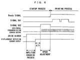
- the following startup process is executed. First, the deflector is driven after emission of the light beam from the light source. Scanning with the light beam is then confirmed based on an output from the optical detection sensor. In the event that the scanning speed of the light beam on the latent image carrier is off a predetermined value, the amplitude of the deflector is changed and the scanning speed is matched with the predetermined value. After the light beam has started scanning on the latent image carrier stably at the predetermined speed, Ready signal which permits the start of printing is output and the startup process ends. Following this, at proper timing, image forming processing is executed based on the image signal.
- the deflector since the deflector operates after emission of the light beam from the light source, the deflector remains in a halt from turning on of the light source until the start of oscillations of the deflector. This keeps exposing one point on the latent image carrier to irradiation with the light beam, causing a problem of deterioration of the latent image carrier. Further, there is another problem described below when a resonant-type oscillation mirror is used as the deflector, owing to the structure and operation of the deflector.
- the polygon mirror When a polygon mirror is used as the deflector, the polygon mirror rotates, as a motor which is a drive source to rotate the polygon mirror is provided with electric power, thereby scanning the light beam over a predetermined scanning width without fail. Hence, as long as the polygon mirror is operating, the light beam scans across the entire scanning width, and concentration of the light beam in a certain portion of the latent image carrier is prevented. Meanwhile, a resonant-type oscillation mirror, receiving the drive signal whose frequency is identical to the characteristic resonant frequency of the oscillation mirror, resonates and achieves a predetermined deflection angle.
- an image forming apparatus comprising: a light source which emits a light beam; an oscillation mirror which has a deflection mirror surface; a latent image carrier which is structured to rotate; a mirror driver which resonates said oscillation mirror so that the deflection mirror surface deflects the light beam from said light source to scan on said latent image carrier which is rotating to perform an image formation; and an optical detection sensor which is disposed on a scanning path of the light beam, detects the scanning light beam and outputs a signal, wherein turning on of said light source is permitted after an amplitude ensuring process is executed, the amplitude ensuring process in which said oscillation mirror is resonated in an amplitude equal to or larger than a minimum amplitude value which is necessary for the scanning light beam to move past said optical detection sensor.
- toner of the color corresponding to the selected developer is supplied onto the surface of the photosensitive member 2 by a developer roller which carries the toner of the selected color.
- the electrostatic latent image on the photosensitive member 2 is visualized in the selected toner color.
- a toner image developed by the developer unit 4 in the manner above is primarily transferred onto an intermediate transfer belt 71 of a transfer unit 7 in a primary transfer region TR1.
- the transfer unit 7 comprises the intermediate transfer belt 71 which runs across a plurality of rollers 72, 73, etc., and a driver (not shown) which drives the roller 73 into rotations to thereby revolve the intermediate transfer belt 71 in a predetermined revolving direction.
- the operation of the respective portions of the apparatus is controlled based on the vertical synchronizing signal Vsync and a horizontal synchronization sensor (Figs. 3 and 4) which will be described later.
- the toner images of the respective colors formed on the photosensitive member 2 are overlaid each other on the intermediate transfer belt 71, thereby forming a color image which will then be secondarily transferred onto a sheet taken out one by one from a cassette 8 and transported along a transportation path F to a secondary transfer region TR2.
- the sheet now bearing the color image is transported to a discharge tray part 51, which is disposed to a top surface portion of the apparatus main body 5, through a fixing unit 9 and a discharge roller 82.
- the discharge roller 82 moves the sheet seating an image on its one surface in the manner above in a switch back motion.
- the sheet is therefore transported along a reverse transportation path FR. While the sheet is returned back to the transportation path F again before arriving at the gate roller 81, the surface of the sheet which abuts on the intermediate transfer belt 71 in the secondary transfer region TR2 and is to receive a transferred image is, at this stage, the opposite surface to the surface which already bears the image. In this fashion, it is possible to form images on the both surfaces of the sheet.
- 113 is an image memory disposed in the main controller 11 for storage of image data fed from an external apparatus such as a host computer via an interface 112.
- Denoted at 106 is a ROM which stores a computation program executed by a CPU 101, control data for control of the engine part EG, etc.
- Denoted at 107 is a RAM which temporarily stores a computation result derived by the CPU 101, other data, etc.
- the deflector 65 is made using a micro machining technique which is an application of semiconductor manufacturing techniques and which aims at forming an integrated micro machine on a semiconductor substrate, and therefore, the deflector 65 is capable of deflecting a light beam reflected by the resonating deflection mirror surface 651 in the main scanning direction X.
- the deflection mirror surface 651 is axially supported so that the deflection mirror surface 651 can freely pivot about a pivot axis which is approximately orthogonal to the main scanning direction X, and the deflection mirror surface 651 pivots about the pivot axis in accordance with external force applied from an activator 652.
- the activator 652 Based on a mirror drive signal from a mirror driver 102c of the exposure controller 102, the activator 652 exerts electrostatic, electromagnetic or mechanical external force upon the deflection mirror surface 651 and makes the deflection mirror surface 651 pivot at the frequency of the mirror drive signal.
- the drive provided by the activator 652 may be one which utilizes electrostatic absorption, electromagnetic force or mechanical force, each driving method of which is already known and will not be described here.
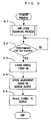
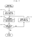
- the displacement detection sensor 653 detects the amount of displacement of the deflection mirror surface 651 and the amplitude value of the deflector 65 is calculated (Step S112), and whether or not this detected value is not less than a predetermined value, namely, a minimum amplitude value is determined (Step S113).
- the "minimum amplitude value” is the amplitude value of the deflection mirror surface 651 which is necessary for the light beam deflected by the deflection mirror surface 651 to move past the horizontal synchronization sensors 60A and 60B.
- this embodiment uses the light source driver 102b which is solely for the startup process, the control is simple. In other words, an image signal suitable to the startup process may be fed from the CPU 101 to the laser source 62, in which case the light source driver 102b is unnecessary.
- the image signal is fed directly from an external apparatus or created based on a print command which is fed from an external apparatus in this type of image forming apparatus, it is necessary to create an adjustment image signal while communicating with the external apparatus.
- the necessity of creating the special image signal (adjustment image signal) which is for adjustment of the drive condition complicates control of telecommunications between this image forming apparatus and the external apparatus which is connected with the image forming apparatus.
- this problem is solved by insertion of the light source driver 102b dedicated to control of the light source for adjustment of the drive condition for the deflector 65.
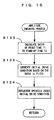
- the initial drive condition is read out from the storage unit 102e (Step S121), and the mirror driver 102c initially sets the drive condition such as the frequency, the voltage, and the like of the mirror drive signal based on the initial drive condition. Then, under this initial drive condition, the oscillation of the deflection mirror surface 651 is started (Step S122).
- the initial drive condition is set in advance corresponding to the deflector 65 as described above.
- the deflector 65 resonates without fail at or over the minimum amplitude value even when the light source is off.
- the laser source 62 thereafter turns on, and therefore, the light beam is already scanning at the time of turning on of the laser source 62, moving past at least the horizontal synchronization sensors 60A and 60B.
- the horizontal synchronization sensors 60A and 60B output the horizontal synchronizing signal Hsync without fail. It is thus possible to adjust the scanning speed of the light beam favorably and highly accurately based on the signal Hsync.
- this embodiment uses the light source driver 102b which is solely for the startup process, the control is simple. In other words, an image signal suitable to the startup process may be fed from the CPU 101 to the laser source 62, in which case the light source driver 102b is unnecessary.
- the image signal is fed directly from an external apparatus or created based on a print command which is fed from an external apparatus in this type of image forming apparatus, it is necessary to create an adjustment image signal while communicating with the external apparatus.
- the necessity of creating the special image signal (adjustment image signal) which is for adjustment of the drive condition complicates control of telecommunications between this image forming apparatus and the external apparatus which is connected with the image forming apparatus.
- this problem is solved by insertion of the light source driver 102b dedicated to control of the light source for adjustment of the drive condition for the deflector 65.
- the deflector 65 thus driven again resonates without fail at or over the minimum amplitude value, namely, the amplitude value of the deflection mirror surface 651 which is needed for the light beam deflected by the deflection mirror surface 651 to move past the horizontal synchronization sensors 60A and 60B.
- the deflector 65 is adjusted and the printing process is performed as in the embodiment above.
- the drive condition for the deflector 65 corresponding to the relationship between the previous print time T1 and the stand-by time T2 may be set as the initial drive condition.
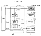
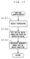
- an initial drive condition is set in accordance with a relationship related to the environment of use of the deflector 65, and the deflector 65 therefore resonates at or over the minimum amplitude value. It then follows that a temperature may be detected directly and the initial drive condition may be set in accordance with the result of the detection. This will now be described with reference to Figs. 16 and 17.
- the temperature sensor 654 detects a temperature inside the apparatus (Step S137).
- the mirror driver 102c initially sets the drive condition such as the frequency, the voltage, and the like of the mirror drive signal based on this initial drive condition, and then, the oscillation of the deflection mirror surface 651 is started under this initial drive condition (Step S134).
- the present invention is not limited to the embodiments above, but may be modified in various manners in addition to the preferred embodiments above, to the extent not deviating from the object of the invention.
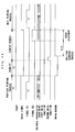
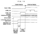
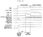
- the photosensitive member 2 may start rotating before the laser source 62 is turned on as shown in Figs. 18 through 21. Since these variations ensure that the photosensitive member 2 is already rotating when the laser source 62 turns on, concentration of the light beam upon the photosensitive member 2 is more effectively prevented and the effect of preventing deterioration of the photosensitive member 2 further improves.
- the amplitude ensuring process (Step S1 in Fig. 5) is executed prior to turning on of the laser source 62 to set the amplitude value of the deflector 65 to the minimum amplitude value or larger in the embodiments above, the upper limit value of the amplitude has not been described specifically. However, it is preferable from the following point of view that the amplitude value of the deflector 65 is set equal to or larger than the minimum amplitude value but equal to or smaller than a maximum amplitude value in the amplitude ensuring process (Step S1 in Fig. 5).
- the scanning light beam keeps irradiating the latent image carrier cartridge CT while the amplitude value is not more than the maximum amplitude value ⁇ max.
- the "maximum amplitude value ⁇ max" is indicative of the rotation angle of the deflection mirror surface 651 as it is when the scanning light beam irradiates an edge portion of the latent image carrier cartridge CT.
- the deflection mirror surface 651 deviates a part of the scanning light from the latent image carrier cartridge CT and the light intrudes into inside the apparatus.
- the light beam thus entering inside the apparatus serves as stray light which is one of major causes of deterioration of an image quality.
- the amplitude value ⁇ of the deflector 65 satisfies the following inequality: ⁇ min ⁇ ⁇ ⁇ ⁇ max in the amplitude ensuring process (Step S1 in Fig. 5) as described above.
- the deflector 65 which is made using a micro machining technique is adopted as an oscillation mirror
- the present invention is applicable to an image forming apparatus in general in which a light beam is deflected using a resonating oscillation mirror and the light beam scans on a latent image carrier.
Landscapes
- Physics & Mathematics (AREA)
- General Physics & Mathematics (AREA)
- Engineering & Computer Science (AREA)
- Multimedia (AREA)
- Signal Processing (AREA)
- Facsimile Scanning Arrangements (AREA)
- Laser Beam Printer (AREA)
- Exposure Or Original Feeding In Electrophotography (AREA)
- Mechanical Optical Scanning Systems (AREA)
- Measurement Of Mechanical Vibrations Or Ultrasonic Waves (AREA)
- Adjustment Of Camera Lenses (AREA)
Abstract
Description
Claims (16)
- An image forming apparatus, comprising:a light source which emits a light beam;an oscillation mirror which has a deflection mirror surface;a latent image carrier which is structured to rotate;a mirror driver which resonates said oscillation mirror so that the deflection mirror surface deflects the light beam from said light source to scan on said latent image carrier which is rotating to perform an image formation; andan optical detection sensor which is disposed on a scanning path of the light beam, detects the scanning light beam and outputs a signal, whereinturning on of said light source is permitted after an amplitude ensuring process is executed, the amplitude ensuring process in which said oscillation mirror is resonated in an amplitude equal to or larger than a minimum amplitude value which is necessary for the scanning light beam to move past said optical detection sensor.
- The image forming apparatus of claim 1, further comprising a displacement detection sensor which is disposed inside or near said oscillation mirror and detects an amount of displacement of the deflection mirror surface, wherein
the amplitude ensuring process is arranged to change and set a drive condition for said oscillation mirror by said mirror driver based on the amount of displacement of the deflection mirror surface detected by said displacement detection sensor, thereby ensuring an amplitude equal to or larger than the minimum amplitude value. - The image forming apparatus of claim 2, further comprising a storage unit which stores an initial drive condition corresponding to said oscillation mirror, wherein
the drive condition for said oscillation mirror in the amplitude ensuring process is set to the initial drive condition when said oscillation mirror starts oscillating but is changed based on the amount of displacement of said deflection mirror surface after said oscillation mirror has started oscillating. - The image forming apparatus of claim 1, further comprising a storage unit which stores an initial drive condition corresponding to said oscillation mirror, wherein
the amplitude ensuring process is arranged to operate said mirror driver based on the initial drive condition which is read out from said storage unit, thereby ensuring an amplitude equal to or larger than the minimum amplitude value. - The image forming apparatus of claim 1, wherein
the amplitude ensuring process is arranged to operate said mirror driver based on an initial drive condition which corresponds to an operating status of said apparatus, thereby ensuring an amplitude equal to or larger than the minimum amplitude value. - The image forming apparatus of claim 5, further comprising a storage unit which stores a first drive condition for said oscillation mirror which is suitable to power-on of said apparatus and a second drive condition for said oscillation mirror which is suitable when said apparatus is in operation, wherein
in executing the amplitude ensuring process, whether said apparatus is immediately after power-on or in operation is determined, and the initial drive condition is set to the first drive condition when said apparatus is immediately after power-on while the initial drive condition is set to the second drive condition when said apparatus is in operation. - The image forming apparatus of claim 5, wherein
said oscillation mirror stops oscillation after completion of previous image formation using said oscillation mirror and remains stand-by until next image formation,
a drive condition for said oscillation mirror which corresponds to a relationship between a time required for the previous image formation and a time of the stand-by is set as the initial drive condition, and
the amplitude ensuring process is executed prior to the next image formation. - The image forming apparatus of claim 5, further comprising a temperature detector which detects a temperature inside said apparatus, wherein
a drive condition for said oscillation mirror which corresponds to the temperature detected by said temperature detector is set as the initial drive condition, and
the amplitude ensuring process is then executed. - The image forming apparatus of any one of claims 2 through 8, wherein
said light source is turned on and the drive condition for said oscillation mirror is adjusted based on an output signal from said optical detection sensor after the amplitude ensuring process is executed but before the image formation is performed. - The image forming apparatus of claim 9, wherein
turning on and off of said light source is controlled based on an image signal and an image corresponding to the image signal is formed after the drive condition for said oscillation mirror is adjusted, and
said apparatus further comprises a light source driver which is dedicated to control of turning on and off of said light source for the purpose of adjusting the drive condition for said oscillation mirror. - The image forming apparatus of any one of claims 1 through 8, further comprising a carrier driver which drives said latent image carrier into rotation, wherein
said carrier driver makes said latent image carrier rotate prior to turning on of said light source. - The image forming apparatus of any one of claims 1 through 8, further comprising a latent image carrier holding member which supports said latent image carrier at both ends of said latent image carrier in the scanning direction of the light beam, wherein
an amplitude value of said oscillation mirror when the scanning light beam irradiates said latent image carrier holding member is defined as a maximum amplitude value, and
in the amplitude ensuring process, said mirror driver resonates said oscillation mirror in an amplitude not less than the minimum amplitude value and not more than the maximum amplitude value. - An image forming method of an apparatus which comprises an oscillation mirror which has a deflection mirror surface, a light source which emits a light beam, and a latent image carrier, said method in which the deflection mirror surface of the oscillation mirror which is resonated deflects the light beam from the light source, and the light beam scans on the latent image carrier to perform an image formation, said method comprising:said startup step comprises:an image forming step of performing the image formation based on a signal which an optical detection sensor which is disposed on a scanning path of the light beam outputs every time the optical detection sensor detects the light beam; anda startup step of stabilizing resonance of the oscillation mirror prior to said image forming step, whereinan amplitude ensuring step of, while maintaining the light source turned off, resonating the oscillation mirror in an amplitude equal to or larger than a minimum amplitude value which is necessary for the scanning light beam to move past the optical detection sensor; andan adjustment step of, after execution of said amplitude ensuring step, turning on the scanning light and adjusting a drive condition for the oscillation mirror based on the signal which the optical detection sensor outputs.
- The image forming method of claim 13, further comprising a setup step of, prior to execution of said startup step, setting an initial drive condition corresponding to the oscillation mirror, wherein
at said amplitude ensuring step, the mirror driver operates under the initial drive condition set at said setup step, thereby ensuring an amplitude equal to or larger than the minimum amplitude value. - The image forming method of claim 13, further comprising a setup step of, prior to execution of said startup step, setting an initial drive condition corresponding to an operating status of said apparatus, wherein
at said amplitude ensuring step, the mirror driver operates under the initial drive condition set at said setup step, thereby ensuring an amplitude equal to or larger than the minimum amplitude value. - The image forming method of claim 14 or 15, wherein the initial drive condition which is set at said setup step is stored in a storage unit in advance.
Priority Applications (1)
| Application Number | Priority Date | Filing Date | Title |
|---|---|---|---|
| EP08005506A EP1950622A3 (en) | 2004-04-20 | 2005-04-18 | Apparatus for and method of forming image using oscillation mirror |
Applications Claiming Priority (8)
| Application Number | Priority Date | Filing Date | Title |
|---|---|---|---|
| JP2004124578A JP2005305773A (en) | 2004-04-20 | 2004-04-20 | Image forming apparatus and image forming method |
| JP2004124577 | 2004-04-20 | ||
| JP2004124576 | 2004-04-20 | ||
| JP2004124577A JP2005305772A (en) | 2004-04-20 | 2004-04-20 | Image forming apparatus and image forming method |
| JP2004124576 | 2004-04-20 | ||
| JP2004124578 | 2004-04-20 | ||
| JP2005039306A JP2005329707A (en) | 2004-04-20 | 2005-02-16 | Image forming apparatus and image forming method |
| JP2005039306 | 2005-02-16 |
Related Child Applications (1)
| Application Number | Title | Priority Date | Filing Date |
|---|---|---|---|
| EP08005506A Division EP1950622A3 (en) | 2004-04-20 | 2005-04-18 | Apparatus for and method of forming image using oscillation mirror |
Publications (2)
| Publication Number | Publication Date |
|---|---|
| EP1589383A1 true EP1589383A1 (en) | 2005-10-26 |
| EP1589383B1 EP1589383B1 (en) | 2008-04-09 |
Family
ID=34935297
Family Applications (2)
| Application Number | Title | Priority Date | Filing Date |
|---|---|---|---|
| EP08005506A Withdrawn EP1950622A3 (en) | 2004-04-20 | 2005-04-18 | Apparatus for and method of forming image using oscillation mirror |
| EP05008395A Expired - Lifetime EP1589383B1 (en) | 2004-04-20 | 2005-04-18 | Apparatus for and method of forming image using oscillation mirror |
Family Applications Before (1)
| Application Number | Title | Priority Date | Filing Date |
|---|---|---|---|
| EP08005506A Withdrawn EP1950622A3 (en) | 2004-04-20 | 2005-04-18 | Apparatus for and method of forming image using oscillation mirror |
Country Status (4)
| Country | Link |
|---|---|
| US (1) | US20050231781A1 (en) |
| EP (2) | EP1950622A3 (en) |
| AT (1) | ATE391943T1 (en) |
| DE (1) | DE602005005891T2 (en) |
Cited By (2)
| Publication number | Priority date | Publication date | Assignee | Title |
|---|---|---|---|---|
| FR3002023A1 (en) * | 2013-02-14 | 2014-08-15 | Valeo Vision | SECURE ADAPTIVE LIGHTING SYSTEM |
| EP2781408A3 (en) * | 2013-03-18 | 2015-05-20 | Stanley Electric Co., Ltd. | Vehicle headlight |
Families Citing this family (6)
| Publication number | Priority date | Publication date | Assignee | Title |
|---|---|---|---|---|
| US8519324B2 (en) * | 2006-09-15 | 2013-08-27 | Nec Corporation | Laser projector for projecting and displaying an image based on the raster scanning of a laser beam |
| JP4965284B2 (en) * | 2007-03-07 | 2012-07-04 | 株式会社リコー | Optical scanning device and image forming device |
| KR101172397B1 (en) * | 2007-08-10 | 2012-08-08 | 삼성전자주식회사 | Light scanning unit, and control method and image forming apparatus having the same |
| JP2011197614A (en) * | 2010-03-24 | 2011-10-06 | Brother Industries Ltd | Optical scanner |
| JP7587994B2 (en) * | 2021-01-28 | 2024-11-21 | 浜松ホトニクス株式会社 | Method for manufacturing an actuator device |
| WO2022219354A1 (en) * | 2021-04-14 | 2022-10-20 | Cambridge Mechatronics Limited | Sma actuator assembly |
Citations (4)
| Publication number | Priority date | Publication date | Assignee | Title |
|---|---|---|---|---|
| JPS6095421A (en) * | 1983-10-29 | 1985-05-28 | Canon Inc | Optical scanning device |
| EP0326411A2 (en) * | 1988-01-29 | 1989-08-02 | Konica Corporation | Image recording apparatus |
| JPH01302316A (en) * | 1988-05-31 | 1989-12-06 | Konica Corp | Image forming device |
| US20030169055A1 (en) * | 2002-03-08 | 2003-09-11 | Klement Martin Christopher | Torsion oscillator stabilization |
Family Cites Families (14)
| Publication number | Priority date | Publication date | Assignee | Title |
|---|---|---|---|---|
| JPH01302317A (en) | 1988-05-31 | 1989-12-06 | Konica Corp | Image forming device |
| US5187364A (en) * | 1989-03-22 | 1993-02-16 | National Research Council Of Canada/Conseil National De Recherches Du Canada | Scanning device with waveform generator optimizer |
| JP2657769B2 (en) | 1994-01-31 | 1997-09-24 | 正喜 江刺 | Planar type galvanometer mirror having displacement detection function and method of manufacturing the same |
| KR100208000B1 (en) * | 1996-09-16 | 1999-07-15 | 윤종용 | Laser scanning unit |
| US5864355A (en) * | 1997-03-20 | 1999-01-26 | Lexmark International, Inc. | Image forming apparatus with laser calibration during ramp-up period of an optical device |
| JP3767163B2 (en) * | 1998-03-26 | 2006-04-19 | コニカミノルタビジネステクノロジーズ株式会社 | Image forming apparatus control method and image forming apparatus |
| JP4585062B2 (en) * | 1999-09-28 | 2010-11-24 | 東芝テック株式会社 | Multi-beam control method |
| JP2001281578A (en) * | 2000-03-30 | 2001-10-10 | Ricoh Co Ltd | Multi-beam scanning apparatus and image forming apparatus |
| US6937372B2 (en) * | 2001-07-11 | 2005-08-30 | Canon Kabushiki Kaisha | Light beam deflecting apparatus, image forming apparatus utilizing the same and drive method therefor |
| US6775039B2 (en) * | 2001-07-13 | 2004-08-10 | Olympus Corporation | Driving circuit for an optical scanner |
| US6538802B2 (en) * | 2001-07-31 | 2003-03-25 | Axsun Technologies, Inc | System and method for tilt mirror calibration due to capacitive sensor drift |
| US20040051033A1 (en) * | 2002-09-13 | 2004-03-18 | Hagen Mark D. | Method of controlling deflection amplitude and offset of a resonant scanning mirror using photo detector timing |
| US6870560B2 (en) * | 2002-12-23 | 2005-03-22 | Lexmark International, Inc. | Bi-directional galvonometric scanning and imaging |
| US7291368B2 (en) * | 2004-04-09 | 2007-11-06 | Chisso Corporation | Liquid crystal composition and liquid crystal display device |
-
2005
- 2005-04-14 US US11/107,383 patent/US20050231781A1/en not_active Abandoned
- 2005-04-18 DE DE602005005891T patent/DE602005005891T2/en not_active Expired - Lifetime
- 2005-04-18 EP EP08005506A patent/EP1950622A3/en not_active Withdrawn
- 2005-04-18 AT AT05008395T patent/ATE391943T1/en not_active IP Right Cessation
- 2005-04-18 EP EP05008395A patent/EP1589383B1/en not_active Expired - Lifetime
Patent Citations (4)
| Publication number | Priority date | Publication date | Assignee | Title |
|---|---|---|---|---|
| JPS6095421A (en) * | 1983-10-29 | 1985-05-28 | Canon Inc | Optical scanning device |
| EP0326411A2 (en) * | 1988-01-29 | 1989-08-02 | Konica Corporation | Image recording apparatus |
| JPH01302316A (en) * | 1988-05-31 | 1989-12-06 | Konica Corp | Image forming device |
| US20030169055A1 (en) * | 2002-03-08 | 2003-09-11 | Klement Martin Christopher | Torsion oscillator stabilization |
Non-Patent Citations (2)
| Title |
|---|
| PATENT ABSTRACTS OF JAPAN vol. 009, no. 243 (P - 392) 30 September 1985 (1985-09-30) * |
| PATENT ABSTRACTS OF JAPAN vol. 014, no. 094 (P - 1010) 21 February 1990 (1990-02-21) * |
Cited By (6)
| Publication number | Priority date | Publication date | Assignee | Title |
|---|---|---|---|---|
| FR3002023A1 (en) * | 2013-02-14 | 2014-08-15 | Valeo Vision | SECURE ADAPTIVE LIGHTING SYSTEM |
| EP2767751A1 (en) * | 2013-02-14 | 2014-08-20 | Valeo Vision | Secure adaptive lighting system |
| CN103994383A (en) * | 2013-02-14 | 2014-08-20 | 法雷奥照明公司 | Secure adaptive lighting system |
| CN103994383B (en) * | 2013-02-14 | 2018-05-11 | 法雷奥照明公司 | The adaptive lighting system of safety |
| EP2781408A3 (en) * | 2013-03-18 | 2015-05-20 | Stanley Electric Co., Ltd. | Vehicle headlight |
| US9335016B2 (en) | 2013-03-18 | 2016-05-10 | Stanley Electric Co., Ltd. | Vehicle headlight |
Also Published As
| Publication number | Publication date |
|---|---|
| EP1950622A2 (en) | 2008-07-30 |
| US20050231781A1 (en) | 2005-10-20 |
| ATE391943T1 (en) | 2008-04-15 |
| DE602005005891T2 (en) | 2009-05-28 |
| EP1589383B1 (en) | 2008-04-09 |
| DE602005005891D1 (en) | 2008-05-21 |
| EP1950622A3 (en) | 2008-08-13 |
Similar Documents
| Publication | Publication Date | Title |
|---|---|---|
| US7557976B2 (en) | Light scanning apparatus and method to prevent damage to an oscillation mirror, reducing its amplitude, in an abnormal control condition via a detection signal outputted to a controller even though the source still emits light | |
| US7602410B2 (en) | Apparatus for and method of forming image using oscillation mirror | |
| US9389533B2 (en) | Image forming apparatus capable of correcting position of image to be formed | |
| EP1589383B1 (en) | Apparatus for and method of forming image using oscillation mirror | |
| JP2007078723A (en) | Optical scanning apparatus, image forming apparatus, and control method | |
| US20090135312A1 (en) | Apparatus For And Method Of Forming Images With Oscillation Mirror | |
| JP2008046548A (en) | Scanning optical apparatus and image forming apparatus | |
| US7557822B2 (en) | Apparatus for and method of forming image using oscillation mirror | |
| US10732558B2 (en) | Image forming apparatus | |
| US7995260B2 (en) | Light scanning device and image forming apparatus | |
| JP4765537B2 (en) | Image forming apparatus | |
| JPH07294839A (en) | Image forming device | |
| JPH11188915A (en) | Method for image forming | |
| JP4935323B2 (en) | Image forming apparatus | |
| US10831123B2 (en) | Information processing apparatus and image forming apparatus | |
| JP2012121230A (en) | Image forming apparatus | |
| JP2007133385A (en) | Optical scanning device | |
| JP2005349621A (en) | Image forming apparatus and light amount adjusting method | |
| JP4501538B2 (en) | Image forming apparatus and image forming method | |
| JP2010000794A (en) | Image formation device and image formation method | |
| JP2003121775A (en) | Light beam scanning device | |
| JP2005305773A (en) | Image forming apparatus and image forming method | |
| JP2005329707A (en) | Image forming apparatus and image forming method | |
| JP2007187731A (en) | Control method of optical scanner | |
| JP2005349623A (en) | Image forming apparatus and image forming method |
Legal Events
| Date | Code | Title | Description |
|---|---|---|---|
| PUAI | Public reference made under article 153(3) epc to a published international application that has entered the european phase |
Free format text: ORIGINAL CODE: 0009012 |
|
| AK | Designated contracting states |
Kind code of ref document: A1 Designated state(s): AT BE BG CH CY CZ DE DK EE ES FI FR GB GR HU IE IS IT LI LT LU MC NL PL PT RO SE SI SK TR |
|
| AX | Request for extension of the european patent |
Extension state: AL BA HR LV MK YU |
|
| 17P | Request for examination filed |
Effective date: 20051017 |
|
| AKX | Designation fees paid |
Designated state(s): AT BE BG CH CY CZ DE DK EE ES FI FR GB GR HU IE IS IT LI LT LU MC NL PL PT RO SE SI SK TR |
|
| GRAC | Information related to communication of intention to grant a patent modified |
Free format text: ORIGINAL CODE: EPIDOSCIGR1 |
|
| GRAP | Despatch of communication of intention to grant a patent |
Free format text: ORIGINAL CODE: EPIDOSNIGR1 |
|
| GRAS | Grant fee paid |
Free format text: ORIGINAL CODE: EPIDOSNIGR3 |
|
| GRAA | (expected) grant |
Free format text: ORIGINAL CODE: 0009210 |
|
| AK | Designated contracting states |
Kind code of ref document: B1 Designated state(s): AT BE BG CH CY CZ DE DK EE ES FI FR GB GR HU IE IS IT LI LT LU MC NL PL PT RO SE SI SK TR |
|
| REG | Reference to a national code |
Ref country code: GB Ref legal event code: FG4D |
|
| REG | Reference to a national code |
Ref country code: CH Ref legal event code: EP |
|
| REG | Reference to a national code |
Ref country code: IE Ref legal event code: FG4D |
|
| REF | Corresponds to: |
Ref document number: 602005005891 Country of ref document: DE Date of ref document: 20080521 Kind code of ref document: P |
|
| PG25 | Lapsed in a contracting state [announced via postgrant information from national office to epo] |
Ref country code: SI Free format text: LAPSE BECAUSE OF FAILURE TO SUBMIT A TRANSLATION OF THE DESCRIPTION OR TO PAY THE FEE WITHIN THE PRESCRIBED TIME-LIMIT Effective date: 20080409 |
|
| NLV1 | Nl: lapsed or annulled due to failure to fulfill the requirements of art. 29p and 29m of the patents act | ||
| PG25 | Lapsed in a contracting state [announced via postgrant information from national office to epo] |
Ref country code: FI Free format text: LAPSE BECAUSE OF FAILURE TO SUBMIT A TRANSLATION OF THE DESCRIPTION OR TO PAY THE FEE WITHIN THE PRESCRIBED TIME-LIMIT Effective date: 20080409 Ref country code: NL Free format text: LAPSE BECAUSE OF FAILURE TO SUBMIT A TRANSLATION OF THE DESCRIPTION OR TO PAY THE FEE WITHIN THE PRESCRIBED TIME-LIMIT Effective date: 20080409 Ref country code: PT Free format text: LAPSE BECAUSE OF FAILURE TO SUBMIT A TRANSLATION OF THE DESCRIPTION OR TO PAY THE FEE WITHIN THE PRESCRIBED TIME-LIMIT Effective date: 20080910 Ref country code: BG Free format text: LAPSE BECAUSE OF FAILURE TO SUBMIT A TRANSLATION OF THE DESCRIPTION OR TO PAY THE FEE WITHIN THE PRESCRIBED TIME-LIMIT Effective date: 20080709 Ref country code: ES Free format text: LAPSE BECAUSE OF FAILURE TO SUBMIT A TRANSLATION OF THE DESCRIPTION OR TO PAY THE FEE WITHIN THE PRESCRIBED TIME-LIMIT Effective date: 20080720 |
|
| ET | Fr: translation filed | ||
| PG25 | Lapsed in a contracting state [announced via postgrant information from national office to epo] |
Ref country code: AT Free format text: LAPSE BECAUSE OF FAILURE TO SUBMIT A TRANSLATION OF THE DESCRIPTION OR TO PAY THE FEE WITHIN THE PRESCRIBED TIME-LIMIT Effective date: 20080409 Ref country code: MC Free format text: LAPSE BECAUSE OF NON-PAYMENT OF DUE FEES Effective date: 20080430 Ref country code: PL Free format text: LAPSE BECAUSE OF FAILURE TO SUBMIT A TRANSLATION OF THE DESCRIPTION OR TO PAY THE FEE WITHIN THE PRESCRIBED TIME-LIMIT Effective date: 20080409 |
|
| PG25 | Lapsed in a contracting state [announced via postgrant information from national office to epo] |
Ref country code: IS Free format text: LAPSE BECAUSE OF FAILURE TO SUBMIT A TRANSLATION OF THE DESCRIPTION OR TO PAY THE FEE WITHIN THE PRESCRIBED TIME-LIMIT Effective date: 20080809 |
|
| PG25 | Lapsed in a contracting state [announced via postgrant information from national office to epo] |
Ref country code: EE Free format text: LAPSE BECAUSE OF FAILURE TO SUBMIT A TRANSLATION OF THE DESCRIPTION OR TO PAY THE FEE WITHIN THE PRESCRIBED TIME-LIMIT Effective date: 20080409 Ref country code: LT Free format text: LAPSE BECAUSE OF FAILURE TO SUBMIT A TRANSLATION OF THE DESCRIPTION OR TO PAY THE FEE WITHIN THE PRESCRIBED TIME-LIMIT Effective date: 20080409 Ref country code: SE Free format text: LAPSE BECAUSE OF FAILURE TO SUBMIT A TRANSLATION OF THE DESCRIPTION OR TO PAY THE FEE WITHIN THE PRESCRIBED TIME-LIMIT Effective date: 20080709 Ref country code: DK Free format text: LAPSE BECAUSE OF FAILURE TO SUBMIT A TRANSLATION OF THE DESCRIPTION OR TO PAY THE FEE WITHIN THE PRESCRIBED TIME-LIMIT Effective date: 20080409 Ref country code: CZ Free format text: LAPSE BECAUSE OF FAILURE TO SUBMIT A TRANSLATION OF THE DESCRIPTION OR TO PAY THE FEE WITHIN THE PRESCRIBED TIME-LIMIT Effective date: 20080409 |
|
| PLBE | No opposition filed within time limit |
Free format text: ORIGINAL CODE: 0009261 |
|
| STAA | Information on the status of an ep patent application or granted ep patent |
Free format text: STATUS: NO OPPOSITION FILED WITHIN TIME LIMIT |
|
| PG25 | Lapsed in a contracting state [announced via postgrant information from national office to epo] |
Ref country code: RO Free format text: LAPSE BECAUSE OF FAILURE TO SUBMIT A TRANSLATION OF THE DESCRIPTION OR TO PAY THE FEE WITHIN THE PRESCRIBED TIME-LIMIT Effective date: 20080409 Ref country code: BE Free format text: LAPSE BECAUSE OF FAILURE TO SUBMIT A TRANSLATION OF THE DESCRIPTION OR TO PAY THE FEE WITHIN THE PRESCRIBED TIME-LIMIT Effective date: 20080409 Ref country code: SK Free format text: LAPSE BECAUSE OF FAILURE TO SUBMIT A TRANSLATION OF THE DESCRIPTION OR TO PAY THE FEE WITHIN THE PRESCRIBED TIME-LIMIT Effective date: 20080409 |
|
| 26N | No opposition filed |
Effective date: 20090112 |
|
| PG25 | Lapsed in a contracting state [announced via postgrant information from national office to epo] |
Ref country code: IE Free format text: LAPSE BECAUSE OF NON-PAYMENT OF DUE FEES Effective date: 20080418 |
|
| PG25 | Lapsed in a contracting state [announced via postgrant information from national office to epo] |
Ref country code: IT Free format text: LAPSE BECAUSE OF FAILURE TO SUBMIT A TRANSLATION OF THE DESCRIPTION OR TO PAY THE FEE WITHIN THE PRESCRIBED TIME-LIMIT Effective date: 20080409 |
|
| PG25 | Lapsed in a contracting state [announced via postgrant information from national office to epo] |
Ref country code: CY Free format text: LAPSE BECAUSE OF FAILURE TO SUBMIT A TRANSLATION OF THE DESCRIPTION OR TO PAY THE FEE WITHIN THE PRESCRIBED TIME-LIMIT Effective date: 20080409 |
|
| REG | Reference to a national code |
Ref country code: CH Ref legal event code: PL |
|
| PG25 | Lapsed in a contracting state [announced via postgrant information from national office to epo] |
Ref country code: LI Free format text: LAPSE BECAUSE OF NON-PAYMENT OF DUE FEES Effective date: 20090430 Ref country code: CH Free format text: LAPSE BECAUSE OF NON-PAYMENT OF DUE FEES Effective date: 20090430 |
|
| PG25 | Lapsed in a contracting state [announced via postgrant information from national office to epo] |
Ref country code: LU Free format text: LAPSE BECAUSE OF NON-PAYMENT OF DUE FEES Effective date: 20080418 Ref country code: HU Free format text: LAPSE BECAUSE OF FAILURE TO SUBMIT A TRANSLATION OF THE DESCRIPTION OR TO PAY THE FEE WITHIN THE PRESCRIBED TIME-LIMIT Effective date: 20081010 |
|
| PG25 | Lapsed in a contracting state [announced via postgrant information from national office to epo] |
Ref country code: TR Free format text: LAPSE BECAUSE OF FAILURE TO SUBMIT A TRANSLATION OF THE DESCRIPTION OR TO PAY THE FEE WITHIN THE PRESCRIBED TIME-LIMIT Effective date: 20080409 |
|
| PG25 | Lapsed in a contracting state [announced via postgrant information from national office to epo] |
Ref country code: GR Free format text: LAPSE BECAUSE OF FAILURE TO SUBMIT A TRANSLATION OF THE DESCRIPTION OR TO PAY THE FEE WITHIN THE PRESCRIBED TIME-LIMIT Effective date: 20080710 |
|
| REG | Reference to a national code |
Ref country code: FR Ref legal event code: PLFP Year of fee payment: 11 |
|
| PGFP | Annual fee paid to national office [announced via postgrant information from national office to epo] |
Ref country code: DE Payment date: 20150414 Year of fee payment: 11 Ref country code: GB Payment date: 20150415 Year of fee payment: 11 |
|
| PGFP | Annual fee paid to national office [announced via postgrant information from national office to epo] |
Ref country code: FR Payment date: 20150408 Year of fee payment: 11 |
|
| REG | Reference to a national code |
Ref country code: DE Ref legal event code: R119 Ref document number: 602005005891 Country of ref document: DE |
|
| GBPC | Gb: european patent ceased through non-payment of renewal fee |
Effective date: 20160418 |
|
| REG | Reference to a national code |
Ref country code: FR Ref legal event code: ST Effective date: 20161230 |
|
| PG25 | Lapsed in a contracting state [announced via postgrant information from national office to epo] |
Ref country code: FR Free format text: LAPSE BECAUSE OF NON-PAYMENT OF DUE FEES Effective date: 20160502 Ref country code: GB Free format text: LAPSE BECAUSE OF NON-PAYMENT OF DUE FEES Effective date: 20160418 Ref country code: DE Free format text: LAPSE BECAUSE OF NON-PAYMENT OF DUE FEES Effective date: 20161101 |