EP1589257A1 - Gearbox architectures for a family of single and double clutch transmissions for motor vehicle - Google Patents
Gearbox architectures for a family of single and double clutch transmissions for motor vehicle Download PDFInfo
- Publication number
- EP1589257A1 EP1589257A1 EP04425283A EP04425283A EP1589257A1 EP 1589257 A1 EP1589257 A1 EP 1589257A1 EP 04425283 A EP04425283 A EP 04425283A EP 04425283 A EP04425283 A EP 04425283A EP 1589257 A1 EP1589257 A1 EP 1589257A1
- Authority
- EP
- European Patent Office
- Prior art keywords
- gear
- gears
- wheels
- wheel
- transmission
- Prior art date
- Legal status (The legal status is an assumption and is not a legal conclusion. Google has not performed a legal analysis and makes no representation as to the accuracy of the status listed.)
- Granted
Links
Images

Classifications
-
- F—MECHANICAL ENGINEERING; LIGHTING; HEATING; WEAPONS; BLASTING
- F16—ENGINEERING ELEMENTS AND UNITS; GENERAL MEASURES FOR PRODUCING AND MAINTAINING EFFECTIVE FUNCTIONING OF MACHINES OR INSTALLATIONS; THERMAL INSULATION IN GENERAL
- F16H—GEARING
- F16H3/00—Toothed gearings for conveying rotary motion with variable gear ratio or for reversing rotary motion
- F16H3/006—Toothed gearings for conveying rotary motion with variable gear ratio or for reversing rotary motion power being selectively transmitted by parallel flow paths, e.g. dual clutch transmissions
-
- F—MECHANICAL ENGINEERING; LIGHTING; HEATING; WEAPONS; BLASTING
- F16—ENGINEERING ELEMENTS AND UNITS; GENERAL MEASURES FOR PRODUCING AND MAINTAINING EFFECTIVE FUNCTIONING OF MACHINES OR INSTALLATIONS; THERMAL INSULATION IN GENERAL
- F16H—GEARING
- F16H3/00—Toothed gearings for conveying rotary motion with variable gear ratio or for reversing rotary motion
- F16H3/02—Toothed gearings for conveying rotary motion with variable gear ratio or for reversing rotary motion without gears having orbital motion
- F16H3/08—Toothed gearings for conveying rotary motion with variable gear ratio or for reversing rotary motion without gears having orbital motion exclusively or essentially with continuously meshing gears, that can be disengaged from their shafts
- F16H3/087—Toothed gearings for conveying rotary motion with variable gear ratio or for reversing rotary motion without gears having orbital motion exclusively or essentially with continuously meshing gears, that can be disengaged from their shafts characterised by the disposition of the gears
- F16H3/093—Toothed gearings for conveying rotary motion with variable gear ratio or for reversing rotary motion without gears having orbital motion exclusively or essentially with continuously meshing gears, that can be disengaged from their shafts characterised by the disposition of the gears with two or more countershafts
-
- F—MECHANICAL ENGINEERING; LIGHTING; HEATING; WEAPONS; BLASTING
- F16—ENGINEERING ELEMENTS AND UNITS; GENERAL MEASURES FOR PRODUCING AND MAINTAINING EFFECTIVE FUNCTIONING OF MACHINES OR INSTALLATIONS; THERMAL INSULATION IN GENERAL
- F16H—GEARING
- F16H3/00—Toothed gearings for conveying rotary motion with variable gear ratio or for reversing rotary motion
- F16H3/02—Toothed gearings for conveying rotary motion with variable gear ratio or for reversing rotary motion without gears having orbital motion
- F16H3/08—Toothed gearings for conveying rotary motion with variable gear ratio or for reversing rotary motion without gears having orbital motion exclusively or essentially with continuously meshing gears, that can be disengaged from their shafts
- F16H3/087—Toothed gearings for conveying rotary motion with variable gear ratio or for reversing rotary motion without gears having orbital motion exclusively or essentially with continuously meshing gears, that can be disengaged from their shafts characterised by the disposition of the gears
- F16H3/093—Toothed gearings for conveying rotary motion with variable gear ratio or for reversing rotary motion without gears having orbital motion exclusively or essentially with continuously meshing gears, that can be disengaged from their shafts characterised by the disposition of the gears with two or more countershafts
- F16H2003/0931—Toothed gearings for conveying rotary motion with variable gear ratio or for reversing rotary motion without gears having orbital motion exclusively or essentially with continuously meshing gears, that can be disengaged from their shafts characterised by the disposition of the gears with two or more countershafts each countershaft having an output gear meshing with a single common gear on the output shaft
-
- F—MECHANICAL ENGINEERING; LIGHTING; HEATING; WEAPONS; BLASTING
- F16—ENGINEERING ELEMENTS AND UNITS; GENERAL MEASURES FOR PRODUCING AND MAINTAINING EFFECTIVE FUNCTIONING OF MACHINES OR INSTALLATIONS; THERMAL INSULATION IN GENERAL
- F16H—GEARING
- F16H2200/00—Transmissions for multiple ratios
- F16H2200/003—Transmissions for multiple ratios characterised by the number of forward speeds
- F16H2200/0052—Transmissions for multiple ratios characterised by the number of forward speeds the gear ratios comprising six forward speeds
-
- F—MECHANICAL ENGINEERING; LIGHTING; HEATING; WEAPONS; BLASTING
- F16—ENGINEERING ELEMENTS AND UNITS; GENERAL MEASURES FOR PRODUCING AND MAINTAINING EFFECTIVE FUNCTIONING OF MACHINES OR INSTALLATIONS; THERMAL INSULATION IN GENERAL
- F16H—GEARING
- F16H2200/00—Transmissions for multiple ratios
- F16H2200/003—Transmissions for multiple ratios characterised by the number of forward speeds
- F16H2200/0056—Transmissions for multiple ratios characterised by the number of forward speeds the gear ratios comprising seven forward speeds
-
- Y—GENERAL TAGGING OF NEW TECHNOLOGICAL DEVELOPMENTS; GENERAL TAGGING OF CROSS-SECTIONAL TECHNOLOGIES SPANNING OVER SEVERAL SECTIONS OF THE IPC; TECHNICAL SUBJECTS COVERED BY FORMER USPC CROSS-REFERENCE ART COLLECTIONS [XRACs] AND DIGESTS
- Y10—TECHNICAL SUBJECTS COVERED BY FORMER USPC
- Y10T—TECHNICAL SUBJECTS COVERED BY FORMER US CLASSIFICATION
- Y10T74/00—Machine element or mechanism
- Y10T74/19—Gearing
- Y10T74/19219—Interchangeably locked
- Y10T74/19233—Plurality of counter shafts
Definitions
- the present invention relates to gearbox architectures for a family of single and double clutch transmissions for motor vehicles, with six or more gears.
- a transmission of this type enables all the gear changes to be made in the so-called "power-shift” mode, in other words with controlled power and torque transfer between the two friction clutches.
- this second type of transmission does not permit changing between fifth and sixth gears in "power-shift" mode.
- the double clutch transmissions for motor vehicles proposed up to the present time have the disadvantage of having a different structure from that of ordinary single clutch transmissions, whether manual or robotized, and therefore they cannot be easily produced from the latter, but require dedicated production systems, with a consequent increase in manufacturing costs.
- the object of the invention is therefore to provide transmission architectures for motor vehicle, with six or more gears, which have a high level of synergy between the double clutch configuration and the corresponding single clutch configuration, whether manual or robotized, so that the manufacturing costs can be reduced with respect to the prior art discussed above.
- a further object of the present invention is to provide transmission architectures for motor vehicle, with six or more gears, which have a simpler structure and smaller overall dimensions, particularly in the axial direction, with respect to the prior art.
- a transmission according to the invention makes it possible to maximize the number of components in common with the single clutch configuration (manual or robotized) and the corresponding double clutch configuration, and to minimize the number of modifications required for changing from one version to the other.
- the two configurations (single and double clutch) of a single transmission can be manufactured on the same production line, and therefore at lower cost.
- a transmission according to the invention offers high flexibility of configuration, since it allows the production of either a very compact and inexpensive manual version or a more sophisticated double clutch version with six or seven gears.
- Another advantage is given by the reduction in the overall axial dimensions and volume of the transmission.
- a further advantage is the minimization of the number of driving wheels, owing to the sharing of the gears.
- the sharing of the reverse gear enables the reverse gear shaft to be dispensed with.
- the gear trains corresponding to the different forward gears of the transmission are indicated in the figures by Roman numerals I, II, III, IV, V, VI and VII, for the first, second, third, fourth, fifth, sixth and seventh gears respectively, while the reverse gear is indicated by the letter R.
- a six-gear double clutch transmission for a motor vehicle basically comprises:
- the first input shaft 110 carries a driving gear wheel 121 of first gear, formed as a ring gear integral with the shaft a driving gear wheel 123 of third gear and a driving gear wheel 125 of fifth gear which are fixed rotationally to the shaft and engage with corresponding driven gear wheels 131 of first gear, 133 of third gear and 135 of fifth gear, idly mounted on the first output shaft 117.
- a first engagement sleeve 141 movable selectively to the left and to the right to engage the first and third gear respectively, is fitted between the two idle driven wheels 131 and 133.
- the second input shaft 112 carries a driving gear wheel 122 of second gear, formed in this case as a ring gear integral with the shaft, and a driving gear wheel 124 of fourth and sixth gear, which are rotationally fixed to the shaft.
- the driving gear wheel or ring gear 122 engages with a driven gear wheel 132 of second gear idly mounted on the second output shaft 119.
- the driving wheel 124 engages both with a driven gear wheel 134 of fourth gear idly mounted on the second output shaft 119 and with a driven gear wheel 136 of sixth gear idly mounted on the first output shaft 117.
- a second engagement sleeve 142 movable selectively to the left and to the right to engage the fifth and sixth gear respectively, is fitted between the two idle driven wheels 135 and 136.
- a third engagement sleeve 143 movable selectively to the left and to the right to engage the second and fourth gear respectively, is fitted between the two idle driven wheels 132 and 134.
- the reverse gear train is obtained by using, as the driving and idle wheel respectively, the gear wheels 121 and 131 of first gear, and as the driven wheel a third wheel 138 idly mounted on the second output shaft 119 and connectable rotationally to this shaft by means of a fourth engagement sleeve 144.
- the gear trains fourth and sixth gears are positioned on the side of the transmission facing the friction clutches 114 and 116, in other words facing the engine, while the gear trains of first and reverse gears are positioned on the axially opposite side.
- this embodiment provides for the use of identical final reduction pinions 119 and 120, with different centre distances between the two output shafts 117 and 119 and the axis of the two input shafts 110 and 112.
- the transmission described above does not permit gear changing in "power-shift” mode between the fifth and sixth gears, since the driven gear wheels 135 and 136 of fifth and sixth, both idly mounted on the first output shaft 117, can be engaged by means of the same engagement sleeve 142.
- this limitation does not adversely affect driving comfort, since the "jerk" occurring in the vehicle on changing between the two highest gears is contained and therefore scarcely noticeable by the driver.
- the two friction clutches 114 and 116 are preferably of the dry type, in order to maximize the transmission efficiency. Additionally, due to the use of a normally engaged friction clutch for the input shaft carrying the driving wheels of first and reverse gears it is possible to dispense with the parking device, by contrast with a solution in which both of the friction clutches are normally disengaged. Since the other friction clutch is normally disengaged, problems (breakage of the gearbox and/or hazards to the user) are also avoided which might arise in case of a failure (electrical, electronic and/or hydraulic fault) in the course of a gear change which requires the simultaneous engagement of the two gears, without the need to adopt an appropriate safety system, which is rather necessary in transmissions in which both of the friction clutches are of the normally engaged type.
- the transmission architecture described above has the advantage that it can be produced easily from a six-gear single clutch transmission, whether manually operated or robotically operated.
- Such a single clutch transmission, in the manually operated version, is shown in Figure 2, in which parts and elements identical or corresponding to those of Figure 1 have been assigned the same reference numbers, increased by 100.
- the double clutch transmission of Figure 1 can be produced from the single clutch transmission of Figure 2 simply by replacing the single input shaft with the two input shafts and by inverting the order of the gear trains of second and third gears.
- the single clutch transmission of Figure 2 can be produced from the double clutch transmission of Figure 1 simply by combining the two input shafts and inverting the order of the gear trains of second and third gears.
- the gear trains of fourth and sixth gears share the driving wheel, indicated 224, and are positioned on the side of the transmission facing the engine. Additionally, as in the transmission of Figure 1, the gear trains of first and reverse gears share the driving wheel, indicated 221, and are positioned on the opposite side of the transmission.
- FIG. 3 A variant of construction of the six-gear single clutch transmission of Figure 2 is shown in Figure 3, in which parts and elements identical or corresponding to those of Figure 2 have been assigned the same reference numbers, increased by 100.
- This variant of construction differs from the embodiment of Figure 2 in that the gear trains of third and fifth gears are shared.
- the sharing of these two gears is made possible by the fact that the gear trains of third and fifth gears are positioned adjacently in the architecture of Figure 2. Therefore, a single driving gear wheel, indicated 323, is is provided, which is connected rotationally to the input shaft 310 and engages both with the driven gear wheel 333 of third gear, idly mounted on the second output shaft 319, and with driven gear wheel 335 of fifth gear, idly mounted on the first output shaft 317. Since these two further gears are shared, a further reduction in the overall axial dimensions of the transmission is achieved with respect to the solution of Figure 2.
- FIG 4 Another preferred embodiment of a double clutch transmission for a motor vehicle according to the invention is shown in Figure 4, in which parts and elements identical or corresponding to those of Figure 1 have been assigned the same reference numbers, increased by 300.
- the transmission has seven gears, with two output shafts 417 and 419 advantageously carrying final reduction pinions 418 and 420 with identical numbers of teeth.
- This constructional solution provides for sharing between the first and reverse gears, between the fourth and sixth gears, and between the fifth and seventh gears.
- a first input shaft 410 carries driving gear wheel 421 of first and reverse gears, formed as a ring gear integral with the shaft, a driving gear wheel 423 of third gear and a driving gear wheel 425 of fifth and seventh gears which are fixed rotationally to the shaft.
- the driving wheels 421 and 423 engage with corresponding driven gear wheels 431 and 433 of first and third gears idly mounted on the first output shaft 417.
- the driving wheel 425 engages with both a driven gear wheel 435 of fifth gear idly mounted on the second output shaft 419 and with a driven gear wheel 437 of seventh gear idly mounted on the first output shaft 417.
- the fifth gear can be engaged by moving to the right a second engagement sleeve 442, for rotationally connecting the idle wheel 435 to the second output shaft 419.
- the seventh gear can be engaged by moving to the left a third engagement sleeve 443 for rotationally connecting the idle wheel 437 to the first output shaft 417.
- a second input shaft 412 carries a driving gear wheel 422 of second gear, formed as a ring gear integral with the shaft, and a driving gear wheel 424 of fourth and sixth gears, which are fixed rotationally to the shaft.
- the driving gear wheel 422 engages with a driven gear wheel 432 of second gear idly mounted on the second output shaft 419.
- the driving wheel 424 engages both with a driven gear wheel 434 of fourth gear idly mounted on the second output shaft 419 and with a driven gear wheel 436 of sixth gear idly mounted on the first output shaft 417.
- a fourth engagement sleeve 444 movable selectively to the left and to the right to engage the second and fourth gear respectively, is fitted between the two idle driven wheels 432 and 434.
- the sixth gear can be engaged by moving the third engagement sleeve 443 to the right in such a way as to rotationally connect the idle wheel 436 to the first output shaft 417.
- the reverse gear train is obtained by using, as the driving and idle wheel respectively, the gear wheels 421 and 431, of first gear and as the driven wheel a third wheel 438 idly mounted on the second output shaft 419 and connectable rotationally to this shaft by means of the second engagement sleeve 442.
- the two gear trains of fourth and sixth gears are positioned on the side of the transmission facing the engine, while the gear trains of first and reverse gears are positioned on the axially opposite side.
- a seven-gear transmission is achieved which has overall axial dimensions substantially equal to those of the six-gear transmission of Figure 1.
- Another advantage of a seven-gear transmission of this type is that its total range is close to that of a continuously variable transmission (CVT), with an unchanged overall efficiency (typical of that of an ordinary discrete gearbox) and a considerable simplification as regards control system.
- the seventh gear is operated by an input shaft (in other words the first shaft 410) associated with a normally engaged friction clutch (in other words the first clutch 414), when driving on a motorway with the seventh gear engaged there is no need to keep the associated friction clutch energized, thereby improving energy efficiency.
- a further six-gear double clutch transmission architecture for a motor vehicle can be obtained in a very simple way and with the maximum amount of synergy from the seven-gear transmission of Figure 4.
- This further architecture is shown in Figure 5, in which parts and elements identical or corresponding to those of Figure 4 have been assigned the same reference numbers, increased by 100.
- the driven wheel 437 of seventh gear is absent and the sixth and seventh gear engagement sleeve (here indicated 543) is of the single engagement type, rather than the double engagement type, since it only has to be used to engage the driven wheel of sixth gear (here indicated 536).
- a transmission is thus achieved which retains the dimensions and almost all of the components of the transmission of Figure 4 and also has the advantage of enabling all the sequential gear changes to be made in power-shift mode.
Landscapes
- Engineering & Computer Science (AREA)
- General Engineering & Computer Science (AREA)
- Mechanical Engineering (AREA)
- Structure Of Transmissions (AREA)
- Arrangement Or Mounting Of Control Devices For Change-Speed Gearing (AREA)
Abstract
Description
- The present invention relates to gearbox architectures for a family of single and double clutch transmissions for motor vehicles, with six or more gears.
- Italian patent application No. TO2001A0002 in the name of the applicant discloses a six-gear double clutch transmission for motor vehicles, which comprises:
- a first and a second coaxial input shaft; a first and a second output shaft;
- a first and a second friction clutch for coupling, respectively, the first and second input shafts to an engine shaft;
- a first group of driving gear wheels associated with the odd gears (first, third and fifth) and with the reverse gear, carried by the first input shaft;
- a second group of driving gear wheels associated with the even gears (second, fourth and sixth), carried by the second input shaft;
- a plurality of driven gear wheels, each associated with a corresponding gear, carried by the output shafts; and
- engagement sleeves, operable selectively to connect rotationally one of the driving wheels to the corresponding input shaft and/or one of the driven wheels to the corresponding output shaft.
-
- A transmission of this type enables all the gear changes to be made in the so-called "power-shift" mode, in other words with controlled power and torque transfer between the two friction clutches.
- Additionally, the unpublished Italian patent application No. TO2003A001023 in the name of the applicant discloses a six-gear double clutch transmission, comprising:
- a first input shaft which carries driving gear wheels of first, third, fifth and sixth gear, as well as for reverse gear;
- a second input shaft, coaxial with the first, which carries driving gear wheels of second and fourth gears;
- a first and a second friction clutch for coupling the first and second input shafts, respectively, to a driving shaft of the motor vehicle;
- at least a first output shaft carrying a plurality of driven gear wheels, each engaging, directly or indirectly, with a corresponding driving gear wheel;
- a first engagement sleeve associated with the driving or driven gear wheels of first and third gears;
- a second engagement sleeve associated with the driving or driven gear wheels of second and fourth gears;
- a third engagement sleeve associated with the driving or driven gear wheels of fifth and sixth gears; and
- a fourth engagement sleeve associated with the driving or driven gear wheel of reverse gear.
-
- Unlike the transmission mentioned above, this second type of transmission does not permit changing between fifth and sixth gears in "power-shift" mode.
- However, the double clutch transmissions for motor vehicles proposed up to the present time have the disadvantage of having a different structure from that of ordinary single clutch transmissions, whether manual or robotized, and therefore they cannot be easily produced from the latter, but require dedicated production systems, with a consequent increase in manufacturing costs.
- The object of the invention is therefore to provide transmission architectures for motor vehicle, with six or more gears, which have a high level of synergy between the double clutch configuration and the corresponding single clutch configuration, whether manual or robotized, so that the manufacturing costs can be reduced with respect to the prior art discussed above. A further object of the present invention is to provide transmission architectures for motor vehicle, with six or more gears, which have a simpler structure and smaller overall dimensions, particularly in the axial direction, with respect to the prior art.
- These and other objects are achieved according to the invention by a transmission having the characteristics specified in the attached claims.
- As will be made clear by the following description, a transmission according to the invention makes it possible to maximize the number of components in common with the single clutch configuration (manual or robotized) and the corresponding double clutch configuration, and to minimize the number of modifications required for changing from one version to the other. Thus the two configurations (single and double clutch) of a single transmission can be manufactured on the same production line, and therefore at lower cost.
- As will be made clear by the following description, it is basically sufficient to invert the arrangement of the gear trains of second and third gears and to combine the two primary shafts in order to change from the double clutch configuration to the single clutch configuration. This is made possible by the special arrangement of the gear trains which provide the different gears, particularly by the fact that the gear trains of first and fifth gears are positioned on the one side of the transmission and the gear trains of fourth and sixth gears are positioned on the other side. This configuration is possible because the direction of engagement of the odd gears is opposite that of the even gears, as in the case of manual gearboxes.
- Additionally, a transmission according to the invention offers high flexibility of configuration, since it allows the production of either a very compact and inexpensive manual version or a more sophisticated double clutch version with six or seven gears.
- Another advantage is given by the reduction in the overall axial dimensions and volume of the transmission. A further advantage is the minimization of the number of driving wheels, owing to the sharing of the gears. In particular, the sharing of the reverse gear enables the reverse gear shaft to be dispensed with.
- Further characteristics and advantages of the invention will be made clear by the following detailed description, provided purely by way of non-limitative example, with reference to the attached drawings, in which:
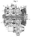
- Figure 1 is a view in axial section of a six-gear double clutch transmission for a motor vehicle according to a first embodiment of the present invention;
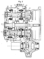
- Figure 2 is a view in axial section of a manually operated six-gear single clutch transmission, which can be produced from the transmission of Figure 1;
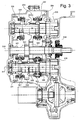
- Figure 3 is a view in axial section of a variant of construction of the six-gear single clutch transmission of Figure 2;
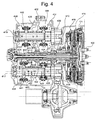
- Figure 4 is a view in axial section of a further preferred embodiment of a motor vehicle transmission of the type with seven gears and double clutch; and
- Figure 5 is a view in axial section of a six-gear double clutch transmission, which can be produced from the transmission of Figure 4.
-
- The gear trains corresponding to the different forward gears of the transmission are indicated in the figures by Roman numerals I, II, III, IV, V, VI and VII, for the first, second, third, fourth, fifth, sixth and seventh gears respectively, while the reverse gear is indicated by the letter R.
- With initial reference to Figure 1, a six-gear double clutch transmission for a motor vehicle according to a first preferred embodiment of the invention basically comprises:
- a
first input shaft 110; - a
second input shaft 112, coaxial with thefirst shaft 110 and made in the form of a hollow shaft in which is inserted the portion of thefirst shaft 110 close to the engine of the motor vehicle (not shown); - a first, normally engaged, friction clutch, generally
indicated 114, for coupling the
first input shaft 110 to a driving shaft 100 (of which only an end portion is shown); - a second, normally disengaged, friction clutch,
generally indicated 116, for coupling the
second input shaft 112 to thedriving shaft 100; - a
first output shaft 117 carrying afinal reduction pinion 118; and - a
second output shaft 119 carrying afinal reduction pinion 120. -
- The
first input shaft 110 carries adriving gear wheel 121 of first gear, formed as a ring gear integral with the shaft adriving gear wheel 123 of third gear and adriving gear wheel 125 of fifth gear which are fixed rotationally to the shaft and engage with corresponding drivengear wheels 131 of first gear, 133 of third gear and 135 of fifth gear, idly mounted on thefirst output shaft 117. Afirst engagement sleeve 141, movable selectively to the left and to the right to engage the first and third gear respectively, is fitted between the two idle drivenwheels - The
second input shaft 112 carries adriving gear wheel 122 of second gear, formed in this case as a ring gear integral with the shaft, and adriving gear wheel 124 of fourth and sixth gear, which are rotationally fixed to the shaft. The driving gear wheel orring gear 122 engages with a drivengear wheel 132 of second gear idly mounted on thesecond output shaft 119. Thedriving wheel 124 engages both with a drivengear wheel 134 of fourth gear idly mounted on thesecond output shaft 119 and with a drivengear wheel 136 of sixth gear idly mounted on thefirst output shaft 117. - A
second engagement sleeve 142, movable selectively to the left and to the right to engage the fifth and sixth gear respectively, is fitted between the two idle drivenwheels third engagement sleeve 143, movable selectively to the left and to the right to engage the second and fourth gear respectively, is fitted between the two idle drivenwheels - The reverse gear train is obtained by using, as the driving and idle wheel respectively, the
gear wheels third wheel 138 idly mounted on thesecond output shaft 119 and connectable rotationally to this shaft by means of afourth engagement sleeve 144. - As is clear from Figure 1, the gear trains fourth and sixth gears are positioned on the side of the transmission facing the
friction clutches - Since the gear trains of first and reverse gears are shared, this variant of construction enables reverse gear to be obtained without the need to provide for dedicated idle wheels or idle shafts. Furthermore, since the gear trains of fourth and sixth gears are also shared, the overall axial dimensions of the transmission are reduced.
- Preferably, this embodiment provides for the use of identical
final reduction pinions output shafts input shafts - The transmission described above does not permit gear changing in "power-shift" mode between the fifth and sixth gears, since the driven
gear wheels first output shaft 117, can be engaged by means of thesame engagement sleeve 142. However, this limitation does not adversely affect driving comfort, since the "jerk" occurring in the vehicle on changing between the two highest gears is contained and therefore scarcely noticeable by the driver. - The two
friction clutches - The transmission architecture described above has the advantage that it can be produced easily from a six-gear single clutch transmission, whether manually operated or robotically operated. Such a single clutch transmission, in the manually operated version, is shown in Figure 2, in which parts and elements identical or corresponding to those of Figure 1 have been assigned the same reference numbers, increased by 100.
- As shown clear by a comparison between Figures 1 and 2, the double clutch transmission of Figure 1 can be produced from the single clutch transmission of Figure 2 simply by replacing the single input shaft with the two input shafts and by inverting the order of the gear trains of second and third gears. Conversely, the single clutch transmission of Figure 2 can be produced from the double clutch transmission of Figure 1 simply by combining the two input shafts and inverting the order of the gear trains of second and third gears.
- In this embodiment also, the gear trains of fourth and sixth gears share the driving wheel, indicated 224, and are positioned on the side of the transmission facing the engine. Additionally, as in the transmission of Figure 1, the gear trains of first and reverse gears share the driving wheel, indicated 221, and are positioned on the opposite side of the transmission.
- A variant of construction of the six-gear single clutch transmission of Figure 2 is shown in Figure 3, in which parts and elements identical or corresponding to those of Figure 2 have been assigned the same reference numbers, increased by 100.
- This variant of construction differs from the embodiment of Figure 2 in that the gear trains of third and fifth gears are shared. The sharing of these two gears is made possible by the fact that the gear trains of third and fifth gears are positioned adjacently in the architecture of Figure 2. Therefore, a single driving gear wheel, indicated 323, is is provided, which is connected rotationally to the
input shaft 310 and engages both with the drivengear wheel 333 of third gear, idly mounted on thesecond output shaft 319, and with drivengear wheel 335 of fifth gear, idly mounted on thefirst output shaft 317. Since these two further gears are shared, a further reduction in the overall axial dimensions of the transmission is achieved with respect to the solution of Figure 2. - Another preferred embodiment of a double clutch transmission for a motor vehicle according to the invention is shown in Figure 4, in which parts and elements identical or corresponding to those of Figure 1 have been assigned the same reference numbers, increased by 300. In this case, the transmission has seven gears, with two
output shafts - A
first input shaft 410 carries drivinggear wheel 421 of first and reverse gears, formed as a ring gear integral with the shaft, adriving gear wheel 423 of third gear and adriving gear wheel 425 of fifth and seventh gears which are fixed rotationally to the shaft. The drivingwheels gear wheels first output shaft 417. Thedriving wheel 425 engages with both a drivengear wheel 435 of fifth gear idly mounted on thesecond output shaft 419 and with a drivengear wheel 437 of seventh gear idly mounted on thefirst output shaft 417. - A
first engagement sleeve 441, movable selectively to the left and to the right to engage the first and third gear respectively, is fitted between the two idle drivenwheels second engagement sleeve 442, for rotationally connecting theidle wheel 435 to thesecond output shaft 419. - The seventh gear can be engaged by moving to the left a
third engagement sleeve 443 for rotationally connecting theidle wheel 437 to thefirst output shaft 417. - A
second input shaft 412 carries adriving gear wheel 422 of second gear, formed as a ring gear integral with the shaft, and adriving gear wheel 424 of fourth and sixth gears, which are fixed rotationally to the shaft. Thedriving gear wheel 422 engages with a drivengear wheel 432 of second gear idly mounted on thesecond output shaft 419. Thedriving wheel 424 engages both with a drivengear wheel 434 of fourth gear idly mounted on thesecond output shaft 419 and with a drivengear wheel 436 of sixth gear idly mounted on thefirst output shaft 417. - A
fourth engagement sleeve 444, movable selectively to the left and to the right to engage the second and fourth gear respectively, is fitted between the two idle drivenwheels third engagement sleeve 443 to the right in such a way as to rotationally connect theidle wheel 436 to thefirst output shaft 417. - The reverse gear train is obtained by using, as the driving and idle wheel respectively, the
gear wheels third wheel 438 idly mounted on thesecond output shaft 419 and connectable rotationally to this shaft by means of thesecond engagement sleeve 442. - In this case also, the two gear trains of fourth and sixth gears are positioned on the side of the transmission facing the engine, while the gear trains of first and reverse gears are positioned on the axially opposite side.
- Since the gear trains of first and reverse gears, of fourth and sixth gears, and of fifth and seventh gears are shared, a seven-gear transmission is achieved which has overall axial dimensions substantially equal to those of the six-gear transmission of Figure 1. Another advantage of a seven-gear transmission of this type is that its total range is close to that of a continuously variable transmission (CVT), with an unchanged overall efficiency (typical of that of an ordinary discrete gearbox) and a considerable simplification as regards control system. Furthermore, since the seventh gear is operated by an input shaft (in other words the first shaft 410) associated with a normally engaged friction clutch (in other words the first clutch 414), when driving on a motorway with the seventh gear engaged there is no need to keep the associated friction clutch energized, thereby improving energy efficiency.
- A further six-gear double clutch transmission architecture for a motor vehicle can be obtained in a very simple way and with the maximum amount of synergy from the seven-gear transmission of Figure 4. This further architecture is shown in Figure 5, in which parts and elements identical or corresponding to those of Figure 4 have been assigned the same reference numbers, increased by 100.
- With respect to the embodiment of Figure 4, the driven
wheel 437 of seventh gear is absent and the sixth and seventh gear engagement sleeve (here indicated 543) is of the single engagement type, rather than the double engagement type, since it only has to be used to engage the driven wheel of sixth gear (here indicated 536). A transmission is thus achieved which retains the dimensions and almost all of the components of the transmission of Figure 4 and also has the advantage of enabling all the sequential gear changes to be made in power-shift mode.
Claims (14)
- Transmission for a motor vehicle with six or more gears, comprising:characterized in that the driven gear wheel (136; 236; 336; 436; 536) associated with the sixth gear (VI) and the driven gear wheel (134; 234; 334; 434; 534) associated with the fourth gear (IV) engage with the same driving gear wheel (124; 224; 324; 424; 524);at least one input shaft (110, 112; 210; 310; 410, 412; 510, 512);at least one friction clutch (114, 116; 414, 416; 514, 516) associated with the said at least one input shaft (110, 112; 210; 310; 410, 412; 510, 512);a first and a second output shaft (117, 119; 217, 219; 317, 319; 417, 419; 517, 519);a plurality of driving gear wheels (121-125; 221-225; 321-324; 421-425; 521-525) carried by the said at least one input shaft (110, 112; 210; 310; 410, 412; 510, 512);a plurality of driven gear wheels (131-136, 138; 231-236, 238; 331-336, 338; 431-438; 531-536, 538) carried by the output shafts (117, 119; 217, 219; 317, 319; 417, 419; 517, 519) and engaging directly or indirectly with the driving gear wheels (121-125; 221-225; 321-324; 421-425; 521-525) to provide the transmission ratios associated with the different gears (I, II, III, IV, V, VI, R; I, II, III, IV, V, VI, VII, R); anda plurality of engagement sleeves (141-144; 241-244; 341-344; 441-444; 541, 544), operable selectively to engage a given gear;
in that the driving gear wheel (124; 224; 324; 424; 524) of fourth and sixth gears (IV, VI), the driven gear wheel (134; 234; 334; 434; 534) of fourth gear (IV) and the driven gear wheel (136; 236; 336; 436; 536) of sixth gear (VI) are positioned on the side of the transmission facing the said at least one friction clutch (114, 116; 414, 416; 514, 516); and in that the driving gear wheels (121; 221; 321; 421; 521) and driven gear wheels (131; 231; 331; 431; 531) associated with the first gear (I) are positioned on the side of the transmission axially opposite that of the aforesaid wheels (IV, VI) of fourth and sixth gears. - Transmission according to Claim 1, in which the gear train of reverse gear (R) comprises the driving gear wheel (121; 221; 321; 421; 521) and the driven gear wheel (131; 231; 331; 431; 531) associated with the first gear (I), operating as a driving wheel and as an idle wheel respectively.
- Transmission according to Claim 1, of the seven-gear type, in which the driven gear wheel (435) associated with the fifth gear (V) and the driven gear wheel (437) associated with the seventh gear (VII) engage with the same driving gear wheel (425).
- Transmission according to Claim 1 or 2, in which the driven gear wheel (333) associated with third gear (III) and the driven gear wheel (335) associated with fifth gear (V) engage with the same driving gear wheel (323).
- Transmission according to any one of the preceding claims, in which the driven gear wheels (131-136, 138; 231-236, 238; 331-336, 338; 431-438; 531-536, 538) are idly mounted on the corresponding output shafts (117, 119; 217, 219; 317, 319; 417, 419; 517, 519).
- Transmission according to Claim 5, in which the driven gear wheels (135, 136; 235, 236; 335; 336; 436, 437) associated with gears N-1 and N (V, VI; VI, VII) are positioned adjacently on the same output shaft (117; 217; 317; 417) and a common engagement sleeve (142; 242; 342; 443) is interposed between these two gear wheels.
- Transmission according to any one of the preceding claims, comprising
a first input shaft (110; 410; 510) carrying the driving gear wheels (121, 123, 125; 421, 423, 425; 521, 523, 525) associated with the odd gears (I, III, V; I, III, V, VII) and with the reverse gear (R);
a second input shaft (112; 412; 512) carrying the driving gear wheels (122, 124; 422, 424; 522, 524) associated with the even gears (II, IV, VI); and
a first and a second friction clutch (114, 116; 414, 416; 514, 516) associated, respectively, with the first and the second input shaft (110, 112; 410, 412; 510, 512). - Transmission according to Claim 7, in which the driven gear wheels (132, 134; 432, 434; 532, 534) associated with the second and fourth gears (II, IV) are positioned adjacently on the second output shaft (119; 419; 519) and a common engagement sleeve (143; 444; 544) is interposed between these two gear wheels.
- Transmission according to Claim 7, in which the driven gear wheels (131, 133; 431, 433; 531, 533) associated with the first and third gears (I, III) are positioned adjacently on the first output shaft (117; 417; 517) and a common engagement sleeve (141; 441; 541) is interposed between these two gear wheels.
- Transmission according to Claim 7, in which the driven gear wheels (435, 438; 535, 538) associated with the fifth gear (V) and with the reverse gear (R) are positioned adjacently on the second output shaft (419; 519) and a common engagement sleeve (442; 542) is interposed between these two gear wheels.
- Transmission according to any one of Claims 7 to 9, in which all the gear changes, except that between the two highest gears (V, VI; VI, VII) can be made in "power-shift" mode.
- Transmission according to Claim 10, of the six gear type, in which all the sequential gear changes can be made in "power-shift" mode.
- Transmission according to Claim 7, in which the first friction clutch (114; 414; 514) is of the normally engaged type, while the second friction clutch (116; 416; 516) is of the normally disengaged type.
- Transmission according to any one of the preceding claims, in which both friction clutches (114, 116; 414, 416; 514, 516) are of the dry type.
Priority Applications (5)
| Application Number | Priority Date | Filing Date | Title |
|---|---|---|---|
| EP04425283A EP1589257B1 (en) | 2004-04-23 | 2004-04-23 | Double clutch transmission for motor vehicle |
| DE602004014248T DE602004014248D1 (en) | 2004-04-23 | 2004-04-23 | Vehicle transmission with double clutch |
| AT04425283T ATE397732T1 (en) | 2004-04-23 | 2004-04-23 | VEHICLE TRANSMISSION WITH DOUBLE CLUTCH |
| US11/111,947 US7258033B2 (en) | 2004-04-23 | 2005-04-22 | Double clutch transmission for motor vehicles |
| CNB2005100674556A CN100380020C (en) | 2004-04-23 | 2005-04-22 | Dual clutch transmission for motor vehicles |
Applications Claiming Priority (1)
| Application Number | Priority Date | Filing Date | Title |
|---|---|---|---|
| EP04425283A EP1589257B1 (en) | 2004-04-23 | 2004-04-23 | Double clutch transmission for motor vehicle |
Publications (2)
| Publication Number | Publication Date |
|---|---|
| EP1589257A1 true EP1589257A1 (en) | 2005-10-26 |
| EP1589257B1 EP1589257B1 (en) | 2008-06-04 |
Family
ID=34932452
Family Applications (1)
| Application Number | Title | Priority Date | Filing Date |
|---|---|---|---|
| EP04425283A Expired - Lifetime EP1589257B1 (en) | 2004-04-23 | 2004-04-23 | Double clutch transmission for motor vehicle |
Country Status (5)
| Country | Link |
|---|---|
| US (1) | US7258033B2 (en) |
| EP (1) | EP1589257B1 (en) |
| CN (1) | CN100380020C (en) |
| AT (1) | ATE397732T1 (en) |
| DE (1) | DE602004014248D1 (en) |
Cited By (4)
| Publication number | Priority date | Publication date | Assignee | Title |
|---|---|---|---|---|
| EP1930626A1 (en) * | 2006-12-04 | 2008-06-11 | C.R.F. Societa Consortile per Azioni | A gearbox with six or more forward gears for single-clutch or twin-clutch motor-vehicle transmission |
| WO2011036394A1 (en) | 2009-09-22 | 2011-03-31 | Peugeot Citroën Automobiles SA | Device for synchronising and rigidly connecting the input shafts of a dual-clutch gearbox |
| CN102927214A (en) * | 2012-10-31 | 2013-02-13 | 奇瑞汽车股份有限公司 | Double clutch speed reducer |
| CN103542044A (en) * | 2013-09-25 | 2014-01-29 | 浙江吉利控股集团有限公司 | Double-clutch automatic gearbox for vehicle |
Families Citing this family (24)
| Publication number | Priority date | Publication date | Assignee | Title |
|---|---|---|---|---|
| ITTO20031023A1 (en) * | 2003-12-18 | 2005-06-19 | Fiat Ricerche | TRANSMISSION ARCHITECTURE WITH DOUBLE CLUTCH FOR MOTOR VEHICLES. |
| KR100610107B1 (en) * | 2004-08-13 | 2006-08-09 | 현대자동차주식회사 | Double clutch transmission |
| WO2006106534A1 (en) * | 2005-04-04 | 2006-10-12 | Graziano Trasmissioni S.P.A. | Seven-gear gearbox for a motorcar double clutch transmission |
| DE602005003461T2 (en) * | 2005-06-09 | 2008-09-25 | C.R.F. Società Consortile per Azioni, Orbassano | Double clutch transmission for motor vehicle |
| US7272986B2 (en) * | 2005-07-15 | 2007-09-25 | Ford Global Technologies, Llc | Dual input automatic transaxle |
| GB0516726D0 (en) * | 2005-08-15 | 2005-09-21 | Ricardo Uk Ltd | Twin layshaft transmission |
| US7490526B2 (en) * | 2006-05-22 | 2009-02-17 | Magna Powertrain Usa, Inc. | Dual clutch powershift transmission with transfer shaft |
| JP5276272B2 (en) * | 2007-03-20 | 2013-08-28 | 株式会社小松製作所 | Industrial vehicle transmission |
| KR100897705B1 (en) | 2007-07-20 | 2009-05-15 | 지엠대우오토앤테크놀로지주식회사 | Front-wheel drive 7-speed manual transmission |
| KR100902719B1 (en) | 2007-07-20 | 2009-06-15 | 지엠대우오토앤테크놀로지주식회사 | Transmission swichable between forward 6 steps and 7 steps |
| DE102008000638B4 (en) * | 2008-03-13 | 2022-05-25 | Zf Friedrichshafen Ag | Actuating device for actuating at least one switching device and method for assembling and disassembling the same |
| DE102008048799A1 (en) * | 2008-04-28 | 2009-11-05 | GIF Gesellschaft für Industrieforschung mbH | Transmission, in particular dual-clutch transmission |
| EP2351949A4 (en) * | 2008-09-24 | 2012-05-16 | Saic Motor Corp Ltd | DOUBLE CLUTCH TRANSMISSION |
| US8511189B2 (en) * | 2008-12-17 | 2013-08-20 | GM Global Technology Operations LLC | Dual clutch multi-speed transmission |
| US8266977B2 (en) * | 2009-04-03 | 2012-09-18 | GM Global Technology Operations LLC | Seven speed dual clutch transmission |
| CN101893067A (en) * | 2009-05-20 | 2010-11-24 | 通用汽车环球科技运作公司 | Seven-gear double-clutch transmission |
| US8459135B2 (en) * | 2009-08-06 | 2013-06-11 | GM Global Technology Operations LLC | Seven speed dual clutch transmission having improved packaging |
| US8485056B2 (en) * | 2009-11-10 | 2013-07-16 | GM Global Technology Operations LLC | Dual clutch multi-speed transmission |
| EP2322371B1 (en) * | 2009-11-13 | 2011-09-28 | C.R.F. Società Consortile per Azioni | Motor-vehicle hybrid propulsion system including a double-clutch transmission with gear shift device comprising a rotary drum |
| DE102009054595A1 (en) * | 2009-12-14 | 2011-06-16 | Zf Friedrichshafen Ag | Double clutch transmission of a motor vehicle |
| US9625006B2 (en) | 2010-03-01 | 2017-04-18 | GM Global Technology Operations LLC | Seven speed dual clutch transmission |
| CN102278428A (en) * | 2010-06-13 | 2011-12-14 | 上海汽车集团股份有限公司 | Dual-clutch transmission gearbox |
| CN103758945A (en) * | 2013-12-25 | 2014-04-30 | 浙江吉利控股集团有限公司 | Dual-clutch automatic transmission |
| JP6111296B2 (en) * | 2015-08-06 | 2017-04-05 | 本田技研工業株式会社 | Transmission with dissimilar metal joint shaft |
Citations (6)
| Publication number | Priority date | Publication date | Assignee | Title |
|---|---|---|---|---|
| US4461188A (en) * | 1981-12-23 | 1984-07-24 | Ford Motor Company | Dual clutch multiple countershaft transmission |
| US5311789A (en) * | 1991-11-06 | 1994-05-17 | Getrag Getriebe-Und Zahnradfabrik H.H. Gmbh | Motor vehicle transmission having gearings for six forward speeds and one reverse speed |
| EP1067312A1 (en) * | 1999-07-05 | 2001-01-10 | Ford Global Technologies, Inc., A subsidiary of Ford Motor Company | Six speed transmission for motor vehicles |
| EP1077336A1 (en) * | 1999-07-05 | 2001-02-21 | Ford Global Technologies, Inc., A subsidiary of Ford Motor Company | Six-speed countershaft transmission system for motor vehicles |
| FR2802600A1 (en) * | 1999-12-16 | 2001-06-22 | Renault | Gearbox has two concentric primary shafts with pinions mounted on them, a drive pinion mounted on a secondary shaft cooperates with a primary shaft pinion and has less teeth then the other drive pinion mounted on another secondary shaft |
| EP1245863A2 (en) * | 2001-03-27 | 2002-10-02 | C.R.F. Società Consortile per Azioni | A motor-vehicle gearbox |
Family Cites Families (9)
| Publication number | Priority date | Publication date | Assignee | Title |
|---|---|---|---|---|
| JPH1151125A (en) * | 1997-08-04 | 1999-02-23 | Toyota Motor Corp | Twin clutch transmission |
| JP2003532040A (en) * | 2000-04-28 | 2003-10-28 | ルーク ラメレン ウント クツプルングスバウ ベタイリグングス コマンディートゲゼルシャフト | Operating device used for double clutch type transmission |
| DE10165097B3 (en) * | 2000-07-18 | 2015-07-23 | Schaeffler Technologies AG & Co. KG | Double clutch |
| GB2372080B (en) * | 2001-02-12 | 2004-09-29 | Luk Lamellen & Kupplungsbau | Hydraulic actuation systems |
| ITTO20010286A1 (en) | 2001-03-27 | 2002-09-27 | Fiat Ricerche | POWER-SHIFT TYPE TRANSMISSION AND MOTOR-DRIVE SYSTEM FOR VEHICLES. |
| JP3598998B2 (en) * | 2001-06-01 | 2004-12-08 | 日産自動車株式会社 | Gear hammering prevention device for twin clutch type gear transmission |
| ITTO20031023A1 (en) * | 2003-12-18 | 2005-06-19 | Fiat Ricerche | TRANSMISSION ARCHITECTURE WITH DOUBLE CLUTCH FOR MOTOR VEHICLES. |
| DE602004006407T2 (en) * | 2004-07-09 | 2008-01-10 | C.R.F. Società Consortile per Azioni, Orbassano | Power-assisted control of a dual-clutch transmission of a vehicle |
| DE602005003461T2 (en) * | 2005-06-09 | 2008-09-25 | C.R.F. Società Consortile per Azioni, Orbassano | Double clutch transmission for motor vehicle |
-
2004
- 2004-04-23 EP EP04425283A patent/EP1589257B1/en not_active Expired - Lifetime
- 2004-04-23 DE DE602004014248T patent/DE602004014248D1/en not_active Expired - Lifetime
- 2004-04-23 AT AT04425283T patent/ATE397732T1/en not_active IP Right Cessation
-
2005
- 2005-04-22 CN CNB2005100674556A patent/CN100380020C/en not_active Expired - Fee Related
- 2005-04-22 US US11/111,947 patent/US7258033B2/en not_active Expired - Lifetime
Patent Citations (6)
| Publication number | Priority date | Publication date | Assignee | Title |
|---|---|---|---|---|
| US4461188A (en) * | 1981-12-23 | 1984-07-24 | Ford Motor Company | Dual clutch multiple countershaft transmission |
| US5311789A (en) * | 1991-11-06 | 1994-05-17 | Getrag Getriebe-Und Zahnradfabrik H.H. Gmbh | Motor vehicle transmission having gearings for six forward speeds and one reverse speed |
| EP1067312A1 (en) * | 1999-07-05 | 2001-01-10 | Ford Global Technologies, Inc., A subsidiary of Ford Motor Company | Six speed transmission for motor vehicles |
| EP1077336A1 (en) * | 1999-07-05 | 2001-02-21 | Ford Global Technologies, Inc., A subsidiary of Ford Motor Company | Six-speed countershaft transmission system for motor vehicles |
| FR2802600A1 (en) * | 1999-12-16 | 2001-06-22 | Renault | Gearbox has two concentric primary shafts with pinions mounted on them, a drive pinion mounted on a secondary shaft cooperates with a primary shaft pinion and has less teeth then the other drive pinion mounted on another secondary shaft |
| EP1245863A2 (en) * | 2001-03-27 | 2002-10-02 | C.R.F. Società Consortile per Azioni | A motor-vehicle gearbox |
Cited By (6)
| Publication number | Priority date | Publication date | Assignee | Title |
|---|---|---|---|---|
| EP1930626A1 (en) * | 2006-12-04 | 2008-06-11 | C.R.F. Societa Consortile per Azioni | A gearbox with six or more forward gears for single-clutch or twin-clutch motor-vehicle transmission |
| US7895910B2 (en) | 2006-12-04 | 2011-03-01 | C.R.F. Societa Consortile Per Azioni | Gearbox with six or more forward gears for single-clutch or twin-clutch motor-vehicle transmissions |
| WO2011036394A1 (en) | 2009-09-22 | 2011-03-31 | Peugeot Citroën Automobiles SA | Device for synchronising and rigidly connecting the input shafts of a dual-clutch gearbox |
| CN102927214A (en) * | 2012-10-31 | 2013-02-13 | 奇瑞汽车股份有限公司 | Double clutch speed reducer |
| CN102927214B (en) * | 2012-10-31 | 2016-01-13 | 奇瑞汽车股份有限公司 | A kind of dual-clutch transmission |
| CN103542044A (en) * | 2013-09-25 | 2014-01-29 | 浙江吉利控股集团有限公司 | Double-clutch automatic gearbox for vehicle |
Also Published As
| Publication number | Publication date |
|---|---|
| CN100380020C (en) | 2008-04-09 |
| ATE397732T1 (en) | 2008-06-15 |
| CN1690471A (en) | 2005-11-02 |
| US20050241424A1 (en) | 2005-11-03 |
| US7258033B2 (en) | 2007-08-21 |
| DE602004014248D1 (en) | 2008-07-17 |
| EP1589257B1 (en) | 2008-06-04 |
Similar Documents
| Publication | Publication Date | Title |
|---|---|---|
| EP1589257B1 (en) | Double clutch transmission for motor vehicle | |
| US7377191B2 (en) | Double clutch transmission | |
| EP1637770B1 (en) | A double-clutch transmission for a motor vehicle | |
| CN101970901B (en) | Vehicle dual clutch transmission | |
| US7690278B2 (en) | Step variable transmission for a motor vehicle | |
| US7409886B2 (en) | Twin clutch transmission with coaxial drive and output | |
| US8789434B2 (en) | Seven speed dual clutch transmission | |
| US7044014B2 (en) | Dual clutch automatic transaxle | |
| EP2141385B1 (en) | Dual clutch multi-speed transaxle | |
| EP2126411B1 (en) | Multiple-ratio dual clutch vehicle transmission | |
| US20110167957A1 (en) | Automatic dual-clutch transmission | |
| EP2126412A1 (en) | Dual clutch transmission with multiple range gearing | |
| JP2004263864A (en) | Automobile transmission of six-gear or seven-gear stages | |
| US20100319473A1 (en) | Seven speed dual clutch transmission with four axes of rotation | |
| US20090266199A1 (en) | Powertrain for an Automotive Vehicle with Multiple-Ratio Gearing and a Dual Power Input Clutch | |
| CN109027144B (en) | Automatic 9-gear double-clutch gearbox | |
| GB2458899A (en) | Dual clutch transmission | |
| EP1531287A1 (en) | Parallel shaft transmission | |
| EP0159141A2 (en) | A change speed transmission | |
| US7114409B2 (en) | Short change gear | |
| US7121161B2 (en) | Parallel shaft transmission | |
| US20180238427A1 (en) | Double gearbox, and method for engaging an overall gear ratio therein | |
| US20140202272A1 (en) | Multi-clutch transmission for a motor vehicle | |
| JP2004176844A (en) | Gear transmission | |
| CN120418556A (en) | Powershift transmission for a motor vehicle transmission embodied in a group configuration, motor vehicle transmission and agricultural or municipal commercial vehicle |
Legal Events
| Date | Code | Title | Description |
|---|---|---|---|
| PUAI | Public reference made under article 153(3) epc to a published international application that has entered the european phase |
Free format text: ORIGINAL CODE: 0009012 |
|
| AK | Designated contracting states |
Kind code of ref document: A1 Designated state(s): AT BE BG CH CY CZ DE DK EE ES FI FR GB GR HU IE IT LI LU MC NL PL PT RO SE SI SK TR |
|
| AX | Request for extension of the european patent |
Extension state: AL HR LT LV MK |
|
| 17P | Request for examination filed |
Effective date: 20060421 |
|
| AKX | Designation fees paid |
Designated state(s): AT BE BG CH CY CZ DE DK EE ES FI FR GB GR HU IE IT LI LU MC NL PL PT RO SE SI SK TR |
|
| 17Q | First examination report despatched |
Effective date: 20061019 |
|
| RTI1 | Title (correction) |
Free format text: DOUBLE CLUTCH TRANSMISSION GEARBOX FOR MOTOR VEHICLE |
|
| GRAP | Despatch of communication of intention to grant a patent |
Free format text: ORIGINAL CODE: EPIDOSNIGR1 |
|
| RIC1 | Information provided on ipc code assigned before grant |
Ipc: F16H 3/093 20060101AFI20071026BHEP |
|
| RIN1 | Information on inventor provided before grant (corrected) |
Inventor name: CAENAZZO, DARIO Inventor name: PREGNOLATO, GIANLUIGI Inventor name: BALDASCINI, FILIPPO Inventor name: MESITI, DOMENICO |
|
| GRAS | Grant fee paid |
Free format text: ORIGINAL CODE: EPIDOSNIGR3 |
|
| GRAA | (expected) grant |
Free format text: ORIGINAL CODE: 0009210 |
|
| RTI1 | Title (correction) |
Free format text: DOUBLE CLUTCH TRANSMISSION FOR MOTOR VEHICLE |
|
| AK | Designated contracting states |
Kind code of ref document: B1 Designated state(s): AT BE BG CH CY CZ DE DK EE ES FI FR GB GR HU IE IT LI LU MC NL PL PT RO SE SI SK TR |
|
| REG | Reference to a national code |
Ref country code: GB Ref legal event code: FG4D |
|
| REG | Reference to a national code |
Ref country code: CH Ref legal event code: EP |
|
| REF | Corresponds to: |
Ref document number: 602004014248 Country of ref document: DE Date of ref document: 20080717 Kind code of ref document: P |
|
| REG | Reference to a national code |
Ref country code: IE Ref legal event code: FG4D |
|
| PG25 | Lapsed in a contracting state [announced via postgrant information from national office to epo] |
Ref country code: SI Free format text: LAPSE BECAUSE OF FAILURE TO SUBMIT A TRANSLATION OF THE DESCRIPTION OR TO PAY THE FEE WITHIN THE PRESCRIBED TIME-LIMIT Effective date: 20080604 Ref country code: ES Free format text: LAPSE BECAUSE OF FAILURE TO SUBMIT A TRANSLATION OF THE DESCRIPTION OR TO PAY THE FEE WITHIN THE PRESCRIBED TIME-LIMIT Effective date: 20080915 Ref country code: FI Free format text: LAPSE BECAUSE OF FAILURE TO SUBMIT A TRANSLATION OF THE DESCRIPTION OR TO PAY THE FEE WITHIN THE PRESCRIBED TIME-LIMIT Effective date: 20080604 |
|
| PG25 | Lapsed in a contracting state [announced via postgrant information from national office to epo] |
Ref country code: NL Free format text: LAPSE BECAUSE OF FAILURE TO SUBMIT A TRANSLATION OF THE DESCRIPTION OR TO PAY THE FEE WITHIN THE PRESCRIBED TIME-LIMIT Effective date: 20080604 Ref country code: PL Free format text: LAPSE BECAUSE OF FAILURE TO SUBMIT A TRANSLATION OF THE DESCRIPTION OR TO PAY THE FEE WITHIN THE PRESCRIBED TIME-LIMIT Effective date: 20080604 Ref country code: AT Free format text: LAPSE BECAUSE OF FAILURE TO SUBMIT A TRANSLATION OF THE DESCRIPTION OR TO PAY THE FEE WITHIN THE PRESCRIBED TIME-LIMIT Effective date: 20080604 |
|
| NLV1 | Nl: lapsed or annulled due to failure to fulfill the requirements of art. 29p and 29m of the patents act | ||
| PG25 | Lapsed in a contracting state [announced via postgrant information from national office to epo] |
Ref country code: PT Free format text: LAPSE BECAUSE OF FAILURE TO SUBMIT A TRANSLATION OF THE DESCRIPTION OR TO PAY THE FEE WITHIN THE PRESCRIBED TIME-LIMIT Effective date: 20081104 Ref country code: SE Free format text: LAPSE BECAUSE OF FAILURE TO SUBMIT A TRANSLATION OF THE DESCRIPTION OR TO PAY THE FEE WITHIN THE PRESCRIBED TIME-LIMIT Effective date: 20080904 Ref country code: CZ Free format text: LAPSE BECAUSE OF FAILURE TO SUBMIT A TRANSLATION OF THE DESCRIPTION OR TO PAY THE FEE WITHIN THE PRESCRIBED TIME-LIMIT Effective date: 20080604 |
|
| PG25 | Lapsed in a contracting state [announced via postgrant information from national office to epo] |
Ref country code: BE Free format text: LAPSE BECAUSE OF FAILURE TO SUBMIT A TRANSLATION OF THE DESCRIPTION OR TO PAY THE FEE WITHIN THE PRESCRIBED TIME-LIMIT Effective date: 20080604 Ref country code: SK Free format text: LAPSE BECAUSE OF FAILURE TO SUBMIT A TRANSLATION OF THE DESCRIPTION OR TO PAY THE FEE WITHIN THE PRESCRIBED TIME-LIMIT Effective date: 20080604 Ref country code: RO Free format text: LAPSE BECAUSE OF FAILURE TO SUBMIT A TRANSLATION OF THE DESCRIPTION OR TO PAY THE FEE WITHIN THE PRESCRIBED TIME-LIMIT Effective date: 20080604 |
|
| PLBE | No opposition filed within time limit |
Free format text: ORIGINAL CODE: 0009261 |
|
| STAA | Information on the status of an ep patent application or granted ep patent |
Free format text: STATUS: NO OPPOSITION FILED WITHIN TIME LIMIT |
|
| PG25 | Lapsed in a contracting state [announced via postgrant information from national office to epo] |
Ref country code: EE Free format text: LAPSE BECAUSE OF FAILURE TO SUBMIT A TRANSLATION OF THE DESCRIPTION OR TO PAY THE FEE WITHIN THE PRESCRIBED TIME-LIMIT Effective date: 20080604 Ref country code: BG Free format text: LAPSE BECAUSE OF FAILURE TO SUBMIT A TRANSLATION OF THE DESCRIPTION OR TO PAY THE FEE WITHIN THE PRESCRIBED TIME-LIMIT Effective date: 20080904 Ref country code: DK Free format text: LAPSE BECAUSE OF FAILURE TO SUBMIT A TRANSLATION OF THE DESCRIPTION OR TO PAY THE FEE WITHIN THE PRESCRIBED TIME-LIMIT Effective date: 20080604 |
|
| 26N | No opposition filed |
Effective date: 20090305 |
|
| REG | Reference to a national code |
Ref country code: CH Ref legal event code: PL |
|
| GBPC | Gb: european patent ceased through non-payment of renewal fee |
Effective date: 20090423 |
|
| PG25 | Lapsed in a contracting state [announced via postgrant information from national office to epo] |
Ref country code: CH Free format text: LAPSE BECAUSE OF NON-PAYMENT OF DUE FEES Effective date: 20090430 Ref country code: LI Free format text: LAPSE BECAUSE OF NON-PAYMENT OF DUE FEES Effective date: 20090430 |
|
| REG | Reference to a national code |
Ref country code: IE Ref legal event code: MM4A |
|
| PG25 | Lapsed in a contracting state [announced via postgrant information from national office to epo] |
Ref country code: GB Free format text: LAPSE BECAUSE OF NON-PAYMENT OF DUE FEES Effective date: 20090423 Ref country code: MC Free format text: LAPSE BECAUSE OF NON-PAYMENT OF DUE FEES Effective date: 20090430 Ref country code: IE Free format text: LAPSE BECAUSE OF NON-PAYMENT OF DUE FEES Effective date: 20090423 |
|
| PG25 | Lapsed in a contracting state [announced via postgrant information from national office to epo] |
Ref country code: GR Free format text: LAPSE BECAUSE OF FAILURE TO SUBMIT A TRANSLATION OF THE DESCRIPTION OR TO PAY THE FEE WITHIN THE PRESCRIBED TIME-LIMIT Effective date: 20080905 |
|
| PG25 | Lapsed in a contracting state [announced via postgrant information from national office to epo] |
Ref country code: LU Free format text: LAPSE BECAUSE OF NON-PAYMENT OF DUE FEES Effective date: 20090423 |
|
| PG25 | Lapsed in a contracting state [announced via postgrant information from national office to epo] |
Ref country code: HU Free format text: LAPSE BECAUSE OF FAILURE TO SUBMIT A TRANSLATION OF THE DESCRIPTION OR TO PAY THE FEE WITHIN THE PRESCRIBED TIME-LIMIT Effective date: 20081205 |
|
| PG25 | Lapsed in a contracting state [announced via postgrant information from national office to epo] |
Ref country code: TR Free format text: LAPSE BECAUSE OF FAILURE TO SUBMIT A TRANSLATION OF THE DESCRIPTION OR TO PAY THE FEE WITHIN THE PRESCRIBED TIME-LIMIT Effective date: 20080604 |
|
| PG25 | Lapsed in a contracting state [announced via postgrant information from national office to epo] |
Ref country code: CY Free format text: LAPSE BECAUSE OF FAILURE TO SUBMIT A TRANSLATION OF THE DESCRIPTION OR TO PAY THE FEE WITHIN THE PRESCRIBED TIME-LIMIT Effective date: 20080604 |
|
| REG | Reference to a national code |
Ref country code: FR Ref legal event code: PLFP Year of fee payment: 13 |
|
| REG | Reference to a national code |
Ref country code: FR Ref legal event code: PLFP Year of fee payment: 14 |
|
| REG | Reference to a national code |
Ref country code: FR Ref legal event code: PLFP Year of fee payment: 15 |
|
| PGFP | Annual fee paid to national office [announced via postgrant information from national office to epo] |
Ref country code: DE Payment date: 20200430 Year of fee payment: 17 Ref country code: FR Payment date: 20200430 Year of fee payment: 17 |
|
| REG | Reference to a national code |
Ref country code: DE Ref legal event code: R119 Ref document number: 602004014248 Country of ref document: DE |
|
| PG25 | Lapsed in a contracting state [announced via postgrant information from national office to epo] |
Ref country code: FR Free format text: LAPSE BECAUSE OF NON-PAYMENT OF DUE FEES Effective date: 20210430 Ref country code: DE Free format text: LAPSE BECAUSE OF NON-PAYMENT OF DUE FEES Effective date: 20211103 |
|
| PGFP | Annual fee paid to national office [announced via postgrant information from national office to epo] |
Ref country code: IT Payment date: 20230322 Year of fee payment: 20 |