EP1589216B1 - Air cleaner for engines - Google Patents
Air cleaner for engines Download PDFInfo
- Publication number
- EP1589216B1 EP1589216B1 EP04009460A EP04009460A EP1589216B1 EP 1589216 B1 EP1589216 B1 EP 1589216B1 EP 04009460 A EP04009460 A EP 04009460A EP 04009460 A EP04009460 A EP 04009460A EP 1589216 B1 EP1589216 B1 EP 1589216B1
- Authority
- EP
- European Patent Office
- Prior art keywords
- air
- case
- air cleaner
- locking
- air inlet
- Prior art date
- Legal status (The legal status is an assumption and is not a legal conclusion. Google has not performed a legal analysis and makes no representation as to the accuracy of the status listed.)
- Expired - Lifetime
Links
- 241000196324 Embryophyta Species 0.000 abstract description 11
- 239000000428 dust Substances 0.000 abstract description 11
- 239000003570 air Substances 0.000 description 93
- 239000000446 fuel Substances 0.000 description 5
- 230000002093 peripheral effect Effects 0.000 description 4
- 238000003780 insertion Methods 0.000 description 3
- 230000037431 insertion Effects 0.000 description 3
- 229920000742 Cotton Polymers 0.000 description 2
- 239000012080 ambient air Substances 0.000 description 2
- 238000002485 combustion reaction Methods 0.000 description 2
- 238000004880 explosion Methods 0.000 description 2
- 238000001914 filtration Methods 0.000 description 2
- 239000002828 fuel tank Substances 0.000 description 2
- 239000000203 mixture Substances 0.000 description 2
- 238000004140 cleaning Methods 0.000 description 1
- 239000004020 conductor Substances 0.000 description 1
- 238000012423 maintenance Methods 0.000 description 1
Images




Classifications
-
- B—PERFORMING OPERATIONS; TRANSPORTING
- B01—PHYSICAL OR CHEMICAL PROCESSES OR APPARATUS IN GENERAL
- B01D—SEPARATION
- B01D46/00—Filters or filtering processes specially modified for separating dispersed particles from gases or vapours
- B01D46/0002—Casings; Housings; Frame constructions
- B01D46/0005—Mounting of filtering elements within casings, housings or frames
-
- B—PERFORMING OPERATIONS; TRANSPORTING
- B01—PHYSICAL OR CHEMICAL PROCESSES OR APPARATUS IN GENERAL
- B01D—SEPARATION
- B01D46/00—Filters or filtering processes specially modified for separating dispersed particles from gases or vapours
- B01D46/24—Particle separators, e.g. dust precipitators, using rigid hollow filter bodies
- B01D46/2403—Particle separators, e.g. dust precipitators, using rigid hollow filter bodies characterised by the physical shape or structure of the filtering element
- B01D46/2411—Filter cartridges
-
- F—MECHANICAL ENGINEERING; LIGHTING; HEATING; WEAPONS; BLASTING
- F02—COMBUSTION ENGINES; HOT-GAS OR COMBUSTION-PRODUCT ENGINE PLANTS
- F02M—SUPPLYING COMBUSTION ENGINES IN GENERAL WITH COMBUSTIBLE MIXTURES OR CONSTITUENTS THEREOF
- F02M35/00—Combustion-air cleaners, air intakes, intake silencers, or induction systems specially adapted for, or arranged on, internal-combustion engines
- F02M35/02—Air cleaners
- F02M35/0201—Housings; Casings; Frame constructions; Lids; Manufacturing or assembling thereof
- F02M35/0202—Manufacturing or assembling; Materials for air cleaner housings
- F02M35/0203—Manufacturing or assembling; Materials for air cleaner housings by using clamps, catches, locks or the like, e.g. for disposable plug-in filter cartridges
-
- F—MECHANICAL ENGINEERING; LIGHTING; HEATING; WEAPONS; BLASTING
- F02—COMBUSTION ENGINES; HOT-GAS OR COMBUSTION-PRODUCT ENGINE PLANTS
- F02M—SUPPLYING COMBUSTION ENGINES IN GENERAL WITH COMBUSTIBLE MIXTURES OR CONSTITUENTS THEREOF
- F02M35/00—Combustion-air cleaners, air intakes, intake silencers, or induction systems specially adapted for, or arranged on, internal-combustion engines
- F02M35/02—Air cleaners
- F02M35/024—Air cleaners using filters, e.g. moistened
- F02M35/02416—Fixing, mounting, supporting or arranging filter elements; Filter element cartridges
- F02M35/02425—Support structures increasing the stability or stiffness of the filter element
-
- F—MECHANICAL ENGINEERING; LIGHTING; HEATING; WEAPONS; BLASTING
- F02—COMBUSTION ENGINES; HOT-GAS OR COMBUSTION-PRODUCT ENGINE PLANTS
- F02M—SUPPLYING COMBUSTION ENGINES IN GENERAL WITH COMBUSTIBLE MIXTURES OR CONSTITUENTS THEREOF
- F02M35/00—Combustion-air cleaners, air intakes, intake silencers, or induction systems specially adapted for, or arranged on, internal-combustion engines
- F02M35/02—Air cleaners
- F02M35/08—Air cleaners with means for removing dust, particles or liquids from cleaners; with means for indicating clogging; with by-pass means; Regeneration of cleaners
-
- B—PERFORMING OPERATIONS; TRANSPORTING
- B01—PHYSICAL OR CHEMICAL PROCESSES OR APPARATUS IN GENERAL
- B01D—SEPARATION
- B01D2279/00—Filters adapted for separating dispersed particles from gases or vapours specially modified for specific uses
- B01D2279/60—Filters adapted for separating dispersed particles from gases or vapours specially modified for specific uses for the intake of internal combustion engines or turbines
-
- F—MECHANICAL ENGINEERING; LIGHTING; HEATING; WEAPONS; BLASTING
- F02—COMBUSTION ENGINES; HOT-GAS OR COMBUSTION-PRODUCT ENGINE PLANTS
- F02B—INTERNAL-COMBUSTION PISTON ENGINES; COMBUSTION ENGINES IN GENERAL
- F02B63/00—Adaptations of engines for driving pumps, hand-held tools or electric generators; Portable combinations of engines with engine-driven devices
- F02B63/02—Adaptations of engines for driving pumps, hand-held tools or electric generators; Portable combinations of engines with engine-driven devices for hand-held tools
Definitions
- the present invention is related to an air cleaner for an engine adapted to a power mower, and more particularly, to one that prevents foreign matter such as weeds, dust, and pebbles from being sucked into the air cleaner to enable clean air to be fed to the engine continuously and prevent the foreign matter from contaminating the carburetor of the engine. (Compare with EP-A-602 591 ).
- the power mower 1 is essentially comprised of a body 11, two front wheels 12, two rear wheels 13, an engine 14, a fuel tank 15 and a handle 16.
- a cutting cylinder (not illustrated) is provided at the bottom of the body 11; both pairs of front wheels 12 and rear wheels 13 are respectively provided in the front and the rear of the body 11; the engine 14 and the fuel tank 15 are mounted on the top of the body 11; the handle 16 extends upwards from the rear of the body 11; a speed controller 151 is provided to the handle 16; and a conductor 152 is used to connect the speed controller 16 to the engine 14.
- the air cleaner 2 includes a case 21, an air cleaner element 22 and a cover 23.
- a case 21 which is closer to the carburetor 3 is provided with an air inlet 211, and a supplementary air inlet 212.
- the supplementary air inlet 212 also functions as a drain.
- a locking member 213 in a long oval shape extends upwards from the center of the case 21.
- An air outlet 214 is provided on the bottom of the locking member 213 and two locking posts 215 are each provided on both sides inside the locking member 213.
- the locking post 215 relates to a hollow pillar and is internally threaded.
- an air passage 216 connecting through the carburetor 3 is disposed below the case 21.
- the air cleaner element 22 has a hollow center at its bottom for the insertions of the locking member 213 and both locking pillars 215 from the case 21.
- a trap 221 in the form of a piece of filtration cotton or paper is provided to the peripheral of the air cleaner element 22.
- a resilient washer 222 is provided on the lower circumference of the air cleaner element 22, and a locking hole 223 is disposed above the air cleaner element 22 at where in relation to the location of the locking pillar 215.
- the cover 23 is a rectangular shape to cover up the case 21 and a through hole 231 is provided on top of the cover 23 in relation to the location of the locking pillar 215 to permit insertion of a fastener 24 for locking purposes.
- the air cleaner element 22 is placed on the locking member 213 inside the case 21 with the locking holes 223 on the air cleaner element 22 located in relation to the locking post 215 and the resilient washer 222 below the air cleaner element 22 flushed to the case to prevent overflow of clean air.
- the cover 23 is then placed upon the case with the through hole 231 on top of the cover 23 located in relation to the locking hole 223 of the air cleaner element 22.
- the fastener 24 is inserted through the locking hole 223 of the air cleaner element 22 via the through hole 231 and locked to the locking post 215.
- the ambient air enters into the case 21 through the air inlet 211 and the supplementary air inlet 212. Vapor and foreign matter carried by the air are filtered with the trap 221 for the vapors to condensate into drops to be drained out of the case 21 through the supplementary air inlet 212. As illustrated in Figs. 1 and 2 , the clean air passing through the trap 221 enters into the air passage 216 through the air outlet 214 to mix with the fuel by the carburetor 3 for keeping the engine 14 running.
- the air inlet 211 is vulnerable to being blocked by weeds and dust resulting in an insufficient supply of fresh air to the carburetor 3 to discharge higher volume of exhaust. Frequent maintenance of the air filter also presents an inconvenience for the user.
- the primary purpose of the present invention is to provide an engine air cleaner for a power mower to supply clean air continuously to the carburetor and prevent weeds, dust, and pebbles from being sucked into the air cleaner and thereby contaminating the carburetor.
- an air cleaner according to claim 1 is provided.
- a fender is provided on the side of the air inlet and air passage of the air cleaner to prevent weeds, dust, and chisels from being sucked into the air filter.
- an air cleaner 4 adapted to an engine 61 is essentially comprised of a case 41, an air cleaner element 42 and a cover 43.
- the case 41 and the cover 43 define a space to accommodate the air cleaner element 42.
- An air inlet 411 is provided on the side at where close to a carburetor 5.
- a hollow tube 412 extends externally from the peripheral of the case 41.
- a supplementary air inlet 413 is provided at the bottom of the case 41 to admit air and to function as a drain.
- a long oval locking member 414 extending upward from the center of the case 41 has at its bottom disposed with an air outlet 415 and two hollow locking posts 416 each internally threaded respectively provided on both sides of the locking member 414.
- An air passage 417 is connecting through a carburetor 5 is provided below the case 41.
- the air passage relates to a hollow tube 419 integrated with the case 41 at its below, and a fender to screen the case 41 is provided by the air passage 417 below the case 41.
- the air cleaner element 42 has a hollow center bottom to merely receive the placement of the locking member 414 and the locking pillars 416 of the case 41.
- a trap 421 usually in the form of a piece of filtration cotton or paper is provided to the peripheral of the air cleaner element 42.
- a resilient washer is mounted to the lower circumference of the air cleaner element 42 and a locking hole 423 is provided on top of the air cleaner element 42 at where in relation to the locking pillar 416.
- the rectangular cover 43 properly covers up the case 41 and a through hole 431 is provided on top of the cover 43 at where in relation to the locking pillar 416 to permit the insertion of a fastener 44 for locking purpose.
- the air cleaner is mounted to the locking member 414 inside the case 41; the locking hole 423 on top of the air cleaner element 42 is disposed at where in relation to the locking pillar 46 while the resilient washer 422 below the air cleaner element 42 is flushed on the case 41 to avoid overflow of the clean air; the cover 43 is placed on the case 41 with the through hole 431 on top of the cover 43 located at where in relation to the locking hole 423 of the air cleaner element 42; and the case 41 is secured to the locking post 416 with the fastener 44 inserted through the locking hole 423 of the air cleaner element 42 via the through hole 431.
- the ambient air enters into the case 41 through the air inlet 411 and the supplementary air inlet 413 from the hollow tube 412 extending externally from the peripheral of the air inlet 411 of the case 41.
- Vapors and foreign matters carried by the air are filtered through the trap 421 of the air cleaner element 42 for the vapors to condensate into drops to be drained out of the case 41 through the supplementary air inlet 413 that functions also as drainage.
- the clean air passing through the trap 421 enters into the air passage 417 through the air outlet 415 of the case 41 to be mixed with the fuel at the carburetor 5, thus to keep the engine 61 running.
- weeds, dust, and chisels ejected during the mowing are stopped from entering into the air cleaner 4 by the fender 418 provided on the side of the air passage 417 below the case 41.
- weeds, dust, and chisels are prevented from an easy ingression into the air inlet 411, and in turn, the air inlet 411 is protected from being blocked.
- the fender 418 shields the carburetor 5 to prevent from being contaminated by weeds, dust, and chisels.
- those weeds, dust, and chisels attempt to enter together with the air into the air cleaner 4, they are stopped by the hollow tube 412 of the case 41, thus to maintain normal operation of the engine.
Landscapes
- Engineering & Computer Science (AREA)
- Chemical & Material Sciences (AREA)
- Mechanical Engineering (AREA)
- General Engineering & Computer Science (AREA)
- Combustion & Propulsion (AREA)
- Chemical Kinetics & Catalysis (AREA)
- Manufacturing & Machinery (AREA)
- Geometry (AREA)
- Physics & Mathematics (AREA)
- Harvester Elements (AREA)
- Filtering Materials (AREA)
- Filtering Of Dispersed Particles In Gases (AREA)
- Cooling, Air Intake And Gas Exhaust, And Fuel Tank Arrangements In Propulsion Units (AREA)
Abstract
Description
- The present invention is related to an air cleaner for an engine adapted to a power mower, and more particularly, to one that prevents foreign matter such as weeds, dust, and pebbles from being sucked into the air cleaner to enable clean air to be fed to the engine continuously and prevent the foreign matter from contaminating the carburetor of the engine. (Compare with
EP-A-602 591 - The air cleaner for engines adapted to power mowers generally available in the market functions to introduce fresh air to be mixed with fuel for combustion and explosion in the engine to generate power. As illustrated in
Figs. 1 and2 of the accompanying drawings, the power mower 1 is essentially comprised of abody 11, twofront wheels 12, tworear wheels 13, anengine 14, afuel tank 15 and ahandle 16. Wherein, a cutting cylinder (not illustrated) is provided at the bottom of thebody 11; both pairs offront wheels 12 andrear wheels 13 are respectively provided in the front and the rear of thebody 11; theengine 14 and thefuel tank 15 are mounted on the top of thebody 11; thehandle 16 extends upwards from the rear of thebody 11; aspeed controller 151 is provided to thehandle 16; and aconductor 152 is used to connect thespeed controller 16 to theengine 14. Once the power mower operates, the fresh air is introduced through anair cleaner 2 into acarburetor 3 to mix with the fuel. The mixture is then imported into theengine 14 for combustion and explosion to create power to drive the cutting cylinder to revolve with the speed to be controlled by thespeed controller 151, thus for the user to steer thehandle 16 for mowing. - Referring to
Figs. 2 and3 , theair cleaner 2 includes acase 21, anair cleaner element 22 and acover 23. Wherein, on one side of thecase 21 which is closer to thecarburetor 3 is provided with anair inlet 211, and asupplementary air inlet 212. In addition to admitting the air, thesupplementary air inlet 212 also functions as a drain. Alocking member 213 in a long oval shape extends upwards from the center of thecase 21. Anair outlet 214 is provided on the bottom of thelocking member 213 and twolocking posts 215 are each provided on both sides inside thelocking member 213. Thelocking post 215 relates to a hollow pillar and is internally threaded. Furthermore, anair passage 216 connecting through thecarburetor 3 is disposed below thecase 21. - The
air cleaner element 22 has a hollow center at its bottom for the insertions of thelocking member 213 and bothlocking pillars 215 from thecase 21. Atrap 221 in the form of a piece of filtration cotton or paper is provided to the peripheral of theair cleaner element 22. Aresilient washer 222 is provided on the lower circumference of theair cleaner element 22, and alocking hole 223 is disposed above theair cleaner element 22 at where in relation to the location of thelocking pillar 215. - The
cover 23 is a rectangular shape to cover up thecase 21 and a throughhole 231 is provided on top of thecover 23 in relation to the location of thelocking pillar 215 to permit insertion of afastener 24 for locking purposes. - As illustrated in
Fig. 3 for the assembly of theair cleaner 2 of the prior art, theair cleaner element 22 is placed on thelocking member 213 inside thecase 21 with thelocking holes 223 on theair cleaner element 22 located in relation to thelocking post 215 and theresilient washer 222 below theair cleaner element 22 flushed to the case to prevent overflow of clean air. Thecover 23 is then placed upon the case with the throughhole 231 on top of thecover 23 located in relation to thelocking hole 223 of theair cleaner element 22. Thefastener 24 is inserted through thelocking hole 223 of theair cleaner element 22 via the throughhole 231 and locked to thelocking post 215. - When the
engine 14 is operating as illustrated inFigs. 1 and3 , the ambient air enters into thecase 21 through theair inlet 211 and thesupplementary air inlet 212. Vapor and foreign matter carried by the air are filtered with thetrap 221 for the vapors to condensate into drops to be drained out of thecase 21 through thesupplementary air inlet 212. As illustrated inFigs. 1 and2 , the clean air passing through thetrap 221 enters into theair passage 216 through theair outlet 214 to mix with the fuel by thecarburetor 3 for keeping theengine 14 running. - However, foreign matter including weeds, dust and pebbles are usually present in the air fed to the power mower in operation. When the air around the
air cleaner 2 enters into thecase 21 through theair inlet 211 and thesupplementary air inlet 212, the foreign matter will be usually sucked into thecase 21 at the same time, and weeds and dust of a smaller size may pass through theair inlet 211 and thesupplementary air inlet 212 may be intercepted by thetrap 221; but larger sized matter may block theair inlet 211 resulting in a higher concentration of air-fuel mixture to discharge the higher volume of exhaust. Furthermore, it requires the user to remove theair cleaner 2 for cleaning. In serious cases, the engine will fail and the foreign matter will contaminate thecarburetor 3. - As described above, the
air inlet 211 is vulnerable to being blocked by weeds and dust resulting in an insufficient supply of fresh air to thecarburetor 3 to discharge higher volume of exhaust. Frequent maintenance of the air filter also presents an inconvenience for the user. - The primary purpose of the present invention is to provide an engine air cleaner for a power mower to supply clean air continuously to the carburetor and prevent weeds, dust, and pebbles from being sucked into the air cleaner and thereby contaminating the carburetor. To achieve this purpose, an air cleaner according to claim 1 is provided. A fender is provided on the side of the air inlet and air passage of the air cleaner to prevent weeds, dust, and chisels from being sucked into the air filter.
- The foregoing object and summary provide only a brief introduction to the present invention. To fully appreciate these and other objects of the present invention as well as the invention itself, all of which will become apparent to those skilled in the art, the following detailed description of the invention and the claims should be read in conjunction with the accompanying drawings. Throughout the specification and drawings identical reference numerals refer to identical or similar parts.
- Many other advantages and features of the present invention will become manifest to those versed in the art upon making reference to the detailed description and the accompanying sheets of drawings in which a preferred structural embodiment incorporating the present invention is shown by way of illustrative example.
-
-
Fig. 1 is a perspective view of a power mower of the prior art. -
Fig. 2 is an exploded view of an air cleaner used in an engine of the power mower of the prior art. -
Fig. 3 is a sectional view showing a local part of the air cleaner of the prior art. -
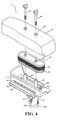
Fig. 4 is an exploded view of an air cleaner of the present invention. -
Fig. 5 is a sectional view showing a local part of the air cleaner of the present invention. -
Fig. 6 is a perspective view showing the present invention adapted to a power mower. - The following descriptions are of exemplary embodiments only, and are not intended to limit the scope, applicability or configuration of the invention in any way. Rather, the following description provides a convenient illustration for implementing exemplary embodiments of the invention. Various changes to the described embodiments may be made in the function and arrangement of the elements described without departing from the scope of the invention as set forth in the appended claims.
- Referring to
Figs. 4 and6 , an air cleaner 4 adapted to anengine 61 is essentially comprised of acase 41, anair cleaner element 42 and acover 43. Thecase 41 and thecover 43 define a space to accommodate theair cleaner element 42. Anair inlet 411 is provided on the side at where close to acarburetor 5. Ahollow tube 412 extends externally from the peripheral of thecase 41. Asupplementary air inlet 413 is provided at the bottom of thecase 41 to admit air and to function as a drain. A longoval locking member 414 extending upward from the center of thecase 41 has at its bottom disposed with anair outlet 415 and twohollow locking posts 416 each internally threaded respectively provided on both sides of thelocking member 414. Anair passage 417 is connecting through acarburetor 5 is provided below thecase 41. The air passage relates to ahollow tube 419 integrated with thecase 41 at its below, and a fender to screen thecase 41 is provided by theair passage 417 below thecase 41. - The
air cleaner element 42 has a hollow center bottom to merely receive the placement of thelocking member 414 and thelocking pillars 416 of thecase 41. Atrap 421 usually in the form ofa piece of filtration cotton or paper is provided to the peripheral of theair cleaner element 42. A resilient washer is mounted to the lower circumference of theair cleaner element 42 and alocking hole 423 is provided on top of theair cleaner element 42 at where in relation to thelocking pillar 416. - The
rectangular cover 43 properly covers up thecase 41 and athrough hole 431 is provided on top of thecover 43 at where in relation to thelocking pillar 416 to permit the insertion of afastener 44 for locking purpose. - As illustrated in
Fig. 5 , upon assembling the air cleaner 4 of the present invention, the air cleaner is mounted to thelocking member 414 inside thecase 41; thelocking hole 423 on top of theair cleaner element 42 is disposed at where in relation to the locking pillar 46 while theresilient washer 422 below theair cleaner element 42 is flushed on thecase 41 to avoid overflow of the clean air; thecover 43 is placed on thecase 41 with thethrough hole 431 on top of thecover 43 located at where in relation to thelocking hole 423 of theair cleaner element 42; and thecase 41 is secured to thelocking post 416 with thefastener 44 inserted through thelocking hole 423 of theair cleaner element 42 via the throughhole 431. - When the
engine 61 is operating as illustrated inFigs. 5 and6 , the ambient air enters into thecase 41 through theair inlet 411 and thesupplementary air inlet 413 from thehollow tube 412 extending externally from the peripheral of theair inlet 411 of thecase 41. Vapors and foreign matters carried by the air are filtered through thetrap 421 of theair cleaner element 42 for the vapors to condensate into drops to be drained out of thecase 41 through thesupplementary air inlet 413 that functions also as drainage. As illustrated inFigs. 4 and6 , the clean air passing through thetrap 421 enters into theair passage 417 through theair outlet 415 of thecase 41 to be mixed with the fuel at thecarburetor 5, thus to keep theengine 61 running. - Now referring to
Figs. 4 and6 , when the present invention is used in a power mower, weeds, dust, and chisels ejected during the mowing are stopped from entering into the air cleaner 4 by thefender 418 provided on the side of theair passage 417 below thecase 41. As stopped by thefender 418, weeds, dust, and chisels are prevented from an easy ingression into theair inlet 411, and in turn, theair inlet 411 is protected from being blocked. Thefender 418 shields thecarburetor 5 to prevent from being contaminated by weeds, dust, and chisels. Furthermore, when those weeds, dust, and chisels attempt to enter together with the air into the air cleaner 4, they are stopped by thehollow tube 412 of thecase 41, thus to maintain normal operation of the engine.
Claims (2)
- An air cleaner (4) for an engine of a mower comprising a case, a cover (43) mounted on said case, and an air cleaner element accommodated in a space defined by said case and said cover; wherein at least an air inlet is provided on one side of said case, a hollow tube extending from said side of said case and communicating with said air inlet, a supplementary air inlet (413) provided at a bottom of said case (41) to admit air and to function as a drain, a locking member provided on said case (41) and having a bottom provided with an air outlet, said air cleaner element being mounted on said locking member, an air passage provided below said case, a hollow tube integrally formed with said bottom of said case and communicating with said air passage, a fender (418) provided by said air passage below said case, said locking member being provided with two locking posts (46) going upwardly through said air cleaner element to engage with two fasteners thereby keeping said air cleaner element and said cover in place.
- The air cleaner for an engine of a mower as claimed in claim 1, wherein said locking member extends upwardly from a center of said case.
Priority Applications (3)
| Application Number | Priority Date | Filing Date | Title |
|---|---|---|---|
| AT04009460T ATE414221T1 (en) | 2004-04-15 | 2004-04-15 | AIR FILTER FOR COMBUSTION ENGINES |
| EP04009460A EP1589216B1 (en) | 2004-04-15 | 2004-04-15 | Air cleaner for engines |
| DE602004017698T DE602004017698D1 (en) | 2004-04-15 | 2004-04-15 | Air filter for internal combustion engines |
Applications Claiming Priority (1)
| Application Number | Priority Date | Filing Date | Title |
|---|---|---|---|
| EP04009460A EP1589216B1 (en) | 2004-04-15 | 2004-04-15 | Air cleaner for engines |
Publications (2)
| Publication Number | Publication Date |
|---|---|
| EP1589216A1 EP1589216A1 (en) | 2005-10-26 |
| EP1589216B1 true EP1589216B1 (en) | 2008-11-12 |
Family
ID=34924678
Family Applications (1)
| Application Number | Title | Priority Date | Filing Date |
|---|---|---|---|
| EP04009460A Expired - Lifetime EP1589216B1 (en) | 2004-04-15 | 2004-04-15 | Air cleaner for engines |
Country Status (3)
| Country | Link |
|---|---|
| EP (1) | EP1589216B1 (en) |
| AT (1) | ATE414221T1 (en) |
| DE (1) | DE602004017698D1 (en) |
Families Citing this family (3)
| Publication number | Priority date | Publication date | Assignee | Title |
|---|---|---|---|---|
| JP5238372B2 (en) * | 2008-06-24 | 2013-07-17 | 本田技研工業株式会社 | Air cleaner for internal combustion engine of walking lawn mower |
| DE202008014211U1 (en) * | 2008-10-24 | 2010-03-11 | Mann+Hummel Gmbh | Air filter for the air supplied to an internal combustion engine in a motor vehicle |
| US10703422B2 (en) | 2018-10-16 | 2020-07-07 | Honda Motor Co., Ltd. | Utility vehicle having a cargo bed with a removable front wall |
Family Cites Families (4)
| Publication number | Priority date | Publication date | Assignee | Title |
|---|---|---|---|---|
| IT214604Z2 (en) * | 1988-06-28 | 1990-05-09 | Iveco Fiat | AIR FILTERING GROUP FOR AN INDUSTRIAL VEHICLE |
| JP3068136B2 (en) * | 1988-11-09 | 2000-07-24 | ヤマハ発動機株式会社 | Air cleaner device for vehicles on uneven terrain |
| JP3569809B2 (en) * | 1992-12-17 | 2004-09-29 | 本田技研工業株式会社 | Motorcycle air cleaner |
| JP3391379B2 (en) * | 2000-02-07 | 2003-03-31 | 川崎重工業株式会社 | Air cleaner and its air intake structure |
-
2004
- 2004-04-15 EP EP04009460A patent/EP1589216B1/en not_active Expired - Lifetime
- 2004-04-15 AT AT04009460T patent/ATE414221T1/en not_active IP Right Cessation
- 2004-04-15 DE DE602004017698T patent/DE602004017698D1/en not_active Expired - Lifetime
Also Published As
| Publication number | Publication date |
|---|---|
| ATE414221T1 (en) | 2008-11-15 |
| EP1589216A1 (en) | 2005-10-26 |
| DE602004017698D1 (en) | 2008-12-24 |
Similar Documents
| Publication | Publication Date | Title |
|---|---|---|
| US6955697B1 (en) | Air cleaner for engines | |
| US4813385A (en) | General-purpose internal combustion engine | |
| US6959934B2 (en) | Air intake system for straddle-type all terrain vehicle | |
| US11712649B2 (en) | Cyclonic air filter assembly for an engine | |
| US7572307B2 (en) | Filter assembly for vacuum cleaner and vacuum cleaner incorporating such assembly | |
| WO2009102988A1 (en) | Raincap precleaner, motor vechile having a raincap precleaner, and method for precleaning air | |
| JPH09100753A (en) | Engine air cleaner | |
| US8105407B2 (en) | Air cleaner for internal combustion engine | |
| DE8221022U1 (en) | HOUSING FOR INTERNAL COMBUSTION ENGINE TO DRIVE A LAWN MOWER | |
| EP1589216A1 (en) | Air cleaner for engines | |
| US20030010706A1 (en) | Diesel fuel with interchangeable cartridge | |
| US20110203864A1 (en) | Hood assembly for a lawn tractor with removable cowl | |
| WO1999025963A1 (en) | Apparatus for cleansing vehicle exhaust gases | |
| JP6688201B2 (en) | General-purpose engine | |
| US20050268582A1 (en) | Motor-vehicle air cleaner | |
| US7621019B2 (en) | Blower apparatus | |
| CN100432412C (en) | Air filter device of engine | |
| US4626266A (en) | Carburetor chamber cover device | |
| US20050103805A1 (en) | Reservoir of fuel delivery module having valve protection structure | |
| DE10354686A1 (en) | Intake system for an internal combustion engine | |
| KR0129307Y1 (en) | Vehicle air suction pipe with filtration device to prevent foreign substances from entering | |
| JP4280150B2 (en) | Engine air cleaner | |
| US20050060973A1 (en) | Air cleaner for portable engine | |
| CN100449138C (en) | air filter of engine | |
| WO2005026522A1 (en) | Air box lid having an integrated filter |
Legal Events
| Date | Code | Title | Description |
|---|---|---|---|
| PUAI | Public reference made under article 153(3) epc to a published international application that has entered the european phase |
Free format text: ORIGINAL CODE: 0009012 |
|
| AK | Designated contracting states |
Kind code of ref document: A1 Designated state(s): AT BE BG CH CY CZ DE DK EE ES FI FR GB GR HU IE IT LI LU MC NL PL PT RO SE SI SK TR |
|
| AX | Request for extension of the european patent |
Extension state: AL HR LT LV MK |
|
| AKX | Designation fees paid |
Designated state(s): AT BE BG CH CY CZ LI |
|
| 17P | Request for examination filed |
Effective date: 20060412 |
|
| RBV | Designated contracting states (corrected) |
Designated state(s): AT BE BG CH CY CZ DE DK EE ES FI FR GB GR HU IE IT LI LU MC NL PL PT RO SE SI SK TR |
|
| REG | Reference to a national code |
Ref country code: DE Ref legal event code: 8566 |
|
| GRAP | Despatch of communication of intention to grant a patent |
Free format text: ORIGINAL CODE: EPIDOSNIGR1 |
|
| GRAS | Grant fee paid |
Free format text: ORIGINAL CODE: EPIDOSNIGR3 |
|
| GRAA | (expected) grant |
Free format text: ORIGINAL CODE: 0009210 |
|
| AK | Designated contracting states |
Kind code of ref document: B1 Designated state(s): AT BE BG CH CY CZ DE DK EE ES FI FR GB GR HU IE IT LI LU MC NL PL PT RO SE SI SK TR |
|
| REG | Reference to a national code |
Ref country code: GB Ref legal event code: FG4D |
|
| REG | Reference to a national code |
Ref country code: CH Ref legal event code: EP |
|
| REG | Reference to a national code |
Ref country code: IE Ref legal event code: FG4D |
|
| REF | Corresponds to: |
Ref document number: 602004017698 Country of ref document: DE Date of ref document: 20081224 Kind code of ref document: P |
|
| REG | Reference to a national code |
Ref country code: GR Ref legal event code: EP Ref document number: 20080403562 Country of ref document: GR |
|
| REG | Reference to a national code |
Ref country code: SE Ref legal event code: TRGR |
|
| PG25 | Lapsed in a contracting state [announced via postgrant information from national office to epo] |
Ref country code: ES Free format text: LAPSE BECAUSE OF FAILURE TO SUBMIT A TRANSLATION OF THE DESCRIPTION OR TO PAY THE FEE WITHIN THE PRESCRIBED TIME-LIMIT Effective date: 20090223 Ref country code: AT Free format text: LAPSE BECAUSE OF FAILURE TO SUBMIT A TRANSLATION OF THE DESCRIPTION OR TO PAY THE FEE WITHIN THE PRESCRIBED TIME-LIMIT Effective date: 20081112 |
|
| NLV1 | Nl: lapsed or annulled due to failure to fulfill the requirements of art. 29p and 29m of the patents act | ||
| PG25 | Lapsed in a contracting state [announced via postgrant information from national office to epo] |
Ref country code: SI Free format text: LAPSE BECAUSE OF FAILURE TO SUBMIT A TRANSLATION OF THE DESCRIPTION OR TO PAY THE FEE WITHIN THE PRESCRIBED TIME-LIMIT Effective date: 20081112 Ref country code: NL Free format text: LAPSE BECAUSE OF FAILURE TO SUBMIT A TRANSLATION OF THE DESCRIPTION OR TO PAY THE FEE WITHIN THE PRESCRIBED TIME-LIMIT Effective date: 20081112 Ref country code: PL Free format text: LAPSE BECAUSE OF FAILURE TO SUBMIT A TRANSLATION OF THE DESCRIPTION OR TO PAY THE FEE WITHIN THE PRESCRIBED TIME-LIMIT Effective date: 20081112 |
|
| PG25 | Lapsed in a contracting state [announced via postgrant information from national office to epo] |
Ref country code: BE Free format text: LAPSE BECAUSE OF FAILURE TO SUBMIT A TRANSLATION OF THE DESCRIPTION OR TO PAY THE FEE WITHIN THE PRESCRIBED TIME-LIMIT Effective date: 20081112 Ref country code: RO Free format text: LAPSE BECAUSE OF FAILURE TO SUBMIT A TRANSLATION OF THE DESCRIPTION OR TO PAY THE FEE WITHIN THE PRESCRIBED TIME-LIMIT Effective date: 20081112 Ref country code: EE Free format text: LAPSE BECAUSE OF FAILURE TO SUBMIT A TRANSLATION OF THE DESCRIPTION OR TO PAY THE FEE WITHIN THE PRESCRIBED TIME-LIMIT Effective date: 20081112 Ref country code: BG Free format text: LAPSE BECAUSE OF FAILURE TO SUBMIT A TRANSLATION OF THE DESCRIPTION OR TO PAY THE FEE WITHIN THE PRESCRIBED TIME-LIMIT Effective date: 20090212 Ref country code: DK Free format text: LAPSE BECAUSE OF FAILURE TO SUBMIT A TRANSLATION OF THE DESCRIPTION OR TO PAY THE FEE WITHIN THE PRESCRIBED TIME-LIMIT Effective date: 20081112 |
|
| PG25 | Lapsed in a contracting state [announced via postgrant information from national office to epo] |
Ref country code: PT Free format text: LAPSE BECAUSE OF FAILURE TO SUBMIT A TRANSLATION OF THE DESCRIPTION OR TO PAY THE FEE WITHIN THE PRESCRIBED TIME-LIMIT Effective date: 20090413 Ref country code: CZ Free format text: LAPSE BECAUSE OF FAILURE TO SUBMIT A TRANSLATION OF THE DESCRIPTION OR TO PAY THE FEE WITHIN THE PRESCRIBED TIME-LIMIT Effective date: 20081112 |
|
| PLBE | No opposition filed within time limit |
Free format text: ORIGINAL CODE: 0009261 |
|
| STAA | Information on the status of an ep patent application or granted ep patent |
Free format text: STATUS: NO OPPOSITION FILED WITHIN TIME LIMIT |
|
| PG25 | Lapsed in a contracting state [announced via postgrant information from national office to epo] |
Ref country code: SK Free format text: LAPSE BECAUSE OF FAILURE TO SUBMIT A TRANSLATION OF THE DESCRIPTION OR TO PAY THE FEE WITHIN THE PRESCRIBED TIME-LIMIT Effective date: 20081112 |
|
| 26N | No opposition filed |
Effective date: 20090813 |
|
| REG | Reference to a national code |
Ref country code: CH Ref legal event code: PL |
|
| GBPC | Gb: european patent ceased through non-payment of renewal fee |
Effective date: 20090415 |
|
| REG | Reference to a national code |
Ref country code: FR Ref legal event code: ST Effective date: 20091231 |
|
| PG25 | Lapsed in a contracting state [announced via postgrant information from national office to epo] |
Ref country code: LI Free format text: LAPSE BECAUSE OF NON-PAYMENT OF DUE FEES Effective date: 20090430 Ref country code: CH Free format text: LAPSE BECAUSE OF NON-PAYMENT OF DUE FEES Effective date: 20090430 |
|
| REG | Reference to a national code |
Ref country code: IE Ref legal event code: MM4A |
|
| PG25 | Lapsed in a contracting state [announced via postgrant information from national office to epo] |
Ref country code: MC Free format text: LAPSE BECAUSE OF NON-PAYMENT OF DUE FEES Effective date: 20090430 Ref country code: FR Free format text: LAPSE BECAUSE OF NON-PAYMENT OF DUE FEES Effective date: 20091222 Ref country code: IE Free format text: LAPSE BECAUSE OF NON-PAYMENT OF DUE FEES Effective date: 20090415 Ref country code: GB Free format text: LAPSE BECAUSE OF NON-PAYMENT OF DUE FEES Effective date: 20090415 |
|
| PG25 | Lapsed in a contracting state [announced via postgrant information from national office to epo] |
Ref country code: IT Free format text: LAPSE BECAUSE OF FAILURE TO SUBMIT A TRANSLATION OF THE DESCRIPTION OR TO PAY THE FEE WITHIN THE PRESCRIBED TIME-LIMIT Effective date: 20081112 |
|
| PG25 | Lapsed in a contracting state [announced via postgrant information from national office to epo] |
Ref country code: LU Free format text: LAPSE BECAUSE OF NON-PAYMENT OF DUE FEES Effective date: 20090415 |
|
| PG25 | Lapsed in a contracting state [announced via postgrant information from national office to epo] |
Ref country code: HU Free format text: LAPSE BECAUSE OF FAILURE TO SUBMIT A TRANSLATION OF THE DESCRIPTION OR TO PAY THE FEE WITHIN THE PRESCRIBED TIME-LIMIT Effective date: 20090513 |
|
| PG25 | Lapsed in a contracting state [announced via postgrant information from national office to epo] |
Ref country code: TR Free format text: LAPSE BECAUSE OF FAILURE TO SUBMIT A TRANSLATION OF THE DESCRIPTION OR TO PAY THE FEE WITHIN THE PRESCRIBED TIME-LIMIT Effective date: 20081112 |
|
| PG25 | Lapsed in a contracting state [announced via postgrant information from national office to epo] |
Ref country code: CY Free format text: LAPSE BECAUSE OF FAILURE TO SUBMIT A TRANSLATION OF THE DESCRIPTION OR TO PAY THE FEE WITHIN THE PRESCRIBED TIME-LIMIT Effective date: 20081112 |
|
| PGFP | Annual fee paid to national office [announced via postgrant information from national office to epo] |
Ref country code: FI Payment date: 20150413 Year of fee payment: 12 Ref country code: SE Payment date: 20150420 Year of fee payment: 12 Ref country code: DE Payment date: 20150327 Year of fee payment: 12 |
|
| PGFP | Annual fee paid to national office [announced via postgrant information from national office to epo] |
Ref country code: GR Payment date: 20150416 Year of fee payment: 12 |
|
| REG | Reference to a national code |
Ref country code: DE Ref legal event code: R119 Ref document number: 602004017698 Country of ref document: DE |
|
| REG | Reference to a national code |
Ref country code: SE Ref legal event code: EUG |
|
| PG25 | Lapsed in a contracting state [announced via postgrant information from national office to epo] |
Ref country code: DE Free format text: LAPSE BECAUSE OF NON-PAYMENT OF DUE FEES Effective date: 20161101 Ref country code: FI Free format text: LAPSE BECAUSE OF NON-PAYMENT OF DUE FEES Effective date: 20160415 |
|
| REG | Reference to a national code |
Ref country code: GR Ref legal event code: ML Ref document number: 20080403562 Country of ref document: GR Effective date: 20161104 |
|
| PG25 | Lapsed in a contracting state [announced via postgrant information from national office to epo] |
Ref country code: GR Free format text: LAPSE BECAUSE OF NON-PAYMENT OF DUE FEES Effective date: 20161104 Ref country code: SE Free format text: LAPSE BECAUSE OF NON-PAYMENT OF DUE FEES Effective date: 20160416 |