EP1589167A2 - Vehicle door handle apparatus - Google Patents
Vehicle door handle apparatus Download PDFInfo
- Publication number
- EP1589167A2 EP1589167A2 EP20050008373 EP05008373A EP1589167A2 EP 1589167 A2 EP1589167 A2 EP 1589167A2 EP 20050008373 EP20050008373 EP 20050008373 EP 05008373 A EP05008373 A EP 05008373A EP 1589167 A2 EP1589167 A2 EP 1589167A2
- Authority
- EP
- European Patent Office
- Prior art keywords
- door handle
- sensor electrode
- vehicle door
- wall portion
- inner space
- Prior art date
- Legal status (The legal status is an assumption and is not a legal conclusion. Google has not performed a legal analysis and makes no representation as to the accuracy of the status listed.)
- Granted
Links
- 229910000859 α-Fe Inorganic materials 0.000 description 3
- 229920003002 synthetic resin Polymers 0.000 description 2
- 239000000057 synthetic resin Substances 0.000 description 2
- 230000002542 deteriorative effect Effects 0.000 description 1
- 239000002184 metal Substances 0.000 description 1
- 229920005989 resin Polymers 0.000 description 1
- 239000011347 resin Substances 0.000 description 1
- 230000008054 signal transmission Effects 0.000 description 1
Images


Classifications
-
- E—FIXED CONSTRUCTIONS
- E05—LOCKS; KEYS; WINDOW OR DOOR FITTINGS; SAFES
- E05B—LOCKS; ACCESSORIES THEREFOR; HANDCUFFS
- E05B81/00—Power-actuated vehicle locks
- E05B81/54—Electrical circuits
- E05B81/64—Monitoring or sensing, e.g. by using switches or sensors
- E05B81/76—Detection of handle operation; Detection of a user approaching a handle; Electrical switching actions performed by door handles
- E05B81/78—Detection of handle operation; Detection of a user approaching a handle; Electrical switching actions performed by door handles as part of a hands-free locking or unlocking operation
-
- E—FIXED CONSTRUCTIONS
- E05—LOCKS; KEYS; WINDOW OR DOOR FITTINGS; SAFES
- E05B—LOCKS; ACCESSORIES THEREFOR; HANDCUFFS
- E05B81/00—Power-actuated vehicle locks
- E05B81/54—Electrical circuits
- E05B81/64—Monitoring or sensing, e.g. by using switches or sensors
- E05B81/76—Detection of handle operation; Detection of a user approaching a handle; Electrical switching actions performed by door handles
- E05B81/77—Detection of handle operation; Detection of a user approaching a handle; Electrical switching actions performed by door handles comprising sensors detecting the presence of the hand of a user
-
- Y—GENERAL TAGGING OF NEW TECHNOLOGICAL DEVELOPMENTS; GENERAL TAGGING OF CROSS-SECTIONAL TECHNOLOGIES SPANNING OVER SEVERAL SECTIONS OF THE IPC; TECHNICAL SUBJECTS COVERED BY FORMER USPC CROSS-REFERENCE ART COLLECTIONS [XRACs] AND DIGESTS
- Y10—TECHNICAL SUBJECTS COVERED BY FORMER USPC
- Y10T—TECHNICAL SUBJECTS COVERED BY FORMER US CLASSIFICATION
- Y10T292/00—Closure fasteners
- Y10T292/82—Knobs
Definitions
- This invention generally relates to a vehicle door handle apparatus. More specifically, this invention pertains to a vehicle door handle apparatus provided with a human approach-detecting sensor for detecting the fact that a hand (a dielectric) of a user of a vehicle is approaching a door handle of a vehicle.
- JP2003-221946A discloses a door handle apparatus.
- This type of door handle apparatus is provided with a door handle and a sensor electrode.
- the door handle includes both an inner space defined therein and a first wall portion having both an operation surface at an outer side thereof and a first inner surface at an inner side thereof, a first inner surface which serves as a part of a surface defining the inner space in the door handle.
- the sensor electrode is allocated within the interior space in such a manner so as to face the first inner surface of the first wall portion, and generates electrostatic capacitance between the sensor electrode and a dielectric approaching the operation surface of the door handle.
- a circuit portion is electrically connected to the sensor electrode.
- a human approach-detecting sensor is thus configured as described above. This circuit portion can detect variations in electrostatic capacitance generated at a time that a hand of a user is approaching the operation surface of the door handle and at a time that the hand is going way therefrom, thereby recognizing the fact that the hand is approaching the door handle.
- a distance of the sensor electrode relative to the operation surface of the first wall portion fluctuates, a distance, which is defined between the sensor electrode and a hand of a user already approaching the operation surface may alter. Therefore, notwithstanding a user's hand has already approached the door handle, there is a danger of the human approach-detecting sensor of failing to detect a user's hand that has approached the door handle, thereby deteriorating a detecting performance of the human approach-detecting sensor.
- the present invention has been made in view of the above circumstances, and provides a vehicle door handle apparatus, which is simply structured and can stabilize a performance of a human approach-detecting sensor in detecting a dielectric.
- a vehicle door handle apparatus includes: a door handle having an inner space therein, a first wall portion having an operation surface at an outer side thereof, and a first inner surface at an inner side thereof, the first inner surface being a part of a surface defining the inner space of the door handle; a sensor electrode positioned inside the inner space so as to face the first inner surface of the first wall portion and capable of generating electrostatic capacitance between the sensor electrode and a dielectric approaching the operation surface; and a controlling member housed within the inner space and capable of adjusting the sensor electrode to come in contact with the inner surface of the first wall portion.
- the door handle includes a second wall portion facing the first wall portion, the second wall portion having a second inner surface at an inner side thereof, the second inner surface being a part of a surface defining the inner space of the door handle, wherein the controlling member projects towards the inner space from the second wall portion.
- the door handle includes both a handle main body, which has the second wall portion and a recessed portion housing the sensor electrode therein, and a cover, which has the first wall portion and fixed to the handle main body so as to close the recessed portion and to define the inner space together with the handle main body.
- controlling member is an elastic member, which is in contact with the second inner surface and biases the sensor electrode towards the first inner space.
- the door handle includes an antenna assembly that is allocated within the inner space and supports the sensor electrode.
- One end of the elastic member is in contact with the second inner surface, and the other end thereof is fixed to the antenna assembly, wherein the elastic member is a spring for biasing the sensor electrode together with the antenna assembly towards the first inner surface.
- Fig. 1 is a perspective view illustrating a vehicle door on which a vehicle door handle apparatus according to an embodiment of the present invention is mounted;
- Fig. 2 is a front view illustrating the vehicle door handle apparatus according to the embodiment of the present invention.
- Fig. 3 is a cross sectional view taken along line I - I in Fig. 2;
- Fig. 4 is a cross sectional view taken along line II - II in Fig. 3;
- Fig. 5 is a side view illustrating an antenna assembly of the vehicle door handle apparatus according to the embodiment of the present invention.
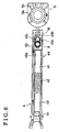
- Fig. 6 is a front view illustrating the antenna assembly of the vehicle door handle apparatus according to the embodiment of the present invention.
- a door outside handle apparatus 2 operated for opening a door 1 of a vehicle is fixed to a door outer panel 11 of the vehicle door 1, and is provided with a door handle 3 gripped by a hand of a user at a time of opening the vehicle door 1.
- This door handle 3 is a bar-shaped handle oriented in a door longitudinal direction (i.e., left and right directions in Figs. 1 and 3) so as to cross a recessed portion 11a of the door outer panel 11.
- the door handle 3 produces, thereon, both a decorative surface 31 openly facing an outside of a vehicle chamber and an operation surface 32 opposite to the decorative surface 31, an operation surface 32 which comes in contact with a hand of a user.
- the door handle 3 is pivotably supported by the door outer panel 11 on a rotational axis of a front end of the door handle 3 (left ends in Figs. 1 and 3) in a manner such that a rear end of the door handle 3 (right ends in Figs. 1 and 3) outstands towards an outside of the vehicle chamber.
- the door handle 3 is further linked to a door lock mechanism (not shown) at the rear end of the door handle 3, a door lock mechanism which is accommodated within the vehicle door 1 and is operated so as to maintain the vehicle door 1 closed.
- the door lock mechanism is operated in response to pivotal movement of the door handle 3 that is gripped by a hand of a user, whereby the vehicle door 1 can be shifted to an open state.
- An open state herein indicates two states; where the vehicle door 1 can be opened, and the vehicle door 1 has been open.
- the door outside handle apparatus 2 is further provided with an antenna 4, which transmits a signal to a portable terminal (not shown) that is carried with a user who intends to open the vehicle door 1, a door switch 5, which activates operation of the door lock mechanism so as to control the vehicle door 1 to a locked state where the vehicle door 1 can not be altered between open and closed states, and a sensor electrode 6 which is one of components that configure a human approach-detecting sensor.
- the sensor electrode 6 activates operation of the door lock mechanism so as to control the vehicle door 1 to an unlocked state where the vehicle door 1 can be altered between the open and closed states.
- the signal is transmitted from the antenna 4 to the portable terminal so as to certify whether a hand of a user is approaching the vehicle door 3.
- the antenna 4 transmits to a portable terminal a signal which requires a certification of a vehicle user approaching the door handle 3.
- the antenna 4 can receive a signal transmitted from a portable terminal, a signal which contains coded information.
- the human approach-detecting sensor is employed so as to start-up operation of the door lock mechanism, operation which is implemented for the purpose of controlling the vehicle door 1 to the unlocked state.
- the human approach-detecting sensor can be employed so as to start-up transmission of a signal from the antenna 4, a signal which requires a certification of a vehicle user approaching the door handle 3.
- the door switch 5 is employed so as to start-up operation of the door lock mechanism, operation which is implemented for the purpose of controlling the vehicle door 1 to the locked state.
- the door switch 5 can be employed, for example, so as to start-up operation of the door lock mechanism for the purpose of controlling the vehicle door 1 to the unlocked state, and to start-up electrically opening and closing the vehicle door 1.
- the door handle 3 is mainly built with a synthetic-resin made handle main body 7 and a synthetic resin made cover 8 attached to the handle main body 7.
- the handle main body 7 and the cover 8 are fixedly coupled to each other in a direction from a vehicle inside towards a vehicle outside (i.e., in up-and-down directions in Figs. 3 and 4) in such a manner that the handle main body 7 possesses the decorative surface 31 and the cover 8 possesses the operation surface 32. Accordingly, it is possible to define an inner space 33 within the door handle 3.
- the handle main body 7 is a bar-shaped member extending in a door longitudinal direction (i.e., the left and right directions in Figs. 1 and 3), and is provided with a supporting leg portion 71 at a front end thereof (left sides in Figs. 1 and 2) and an operating leg portion 72 at a rear end thereof (right sides in Figs. 1 and 2).
- the supporting leg portion 71 acts as a part of a rotational axis of pivotal movement of the door handle 3
- the operating leg portion 72 acts as a connecting portion for connecting the handle main body 7 to the door lock mechanism.
- At an area between the supporting leg portion 71 and the operating leg portion 72 there is a recessed portion 73 defined along a door handle longitudinal direction.
- a bottom wall 73a of the bottom wall 73a is intended to produce, by use of an inner surface 73b of the bottom wall 73a, the inner space 33 within the door handle 3.
- An outer surface 73c of the bottom wall 73a produces thereon the decorative surface 31 of the door handle 3.
- the cover 8 is flat plate-shaped and possesses a plate portion 81 (i.e. a first wall portion) of which lateral thickness is predetermined. At the front end, the cover 8 is fastened to the handle main body 7 in such a manner of closing the recessed portion 73 of the handle main body 7. At the rear end, the cover 8 is screwed to the handle main body 7.
- the plate portion 81 of the cover 8 is intended to define, by use of an inner surface 81a (i.e. a first inner surface) of the plate portion 81, the inner space 33 within the door handle 3.
- An outer surface 81b of the plate portion 81 produces thereon the operation surface 32 of the door handle 3.
- the antenna 4 incorporates, therein, a ferrite core 41, a coil 42 wound on the ferrite core 41, and a harness 44 electrically connected to the coil 42.
- the ferrite core 41 furnished with the coil 42 is housed within an antenna case 43, and is fastened at the antenna case 43 by pawls 43a integrally formed at the antenna case 43.
- An antenna assembly 4A is thus built as described above.
- This antenna assembly 4A is accommodated within the recessed portion 73 of the handle main body 7, and is allocated within the inner space 33 of the door handle 3 in such a manner that the antenna assembly 4A faces the inner surface 73b of the handle main body 7 and the inner surface 81a of the cover 8.
- the antenna assembly 4A can be tightly seated on the cover 8 by fitting a pin 83 protruding from the inner surface 81a of the cover 8 into an engagement bore 43d of the antenna case 43.
- the harness 44 of the antenna 4 extends from the front-end side (the left side in Fig. 3) of the antenna assembly 4A, and then is guided into the vehicle door 1 from a vicinity of the supporting leg portion 71.
- the door switch 5 is made up with a push-type switch 51, a harness 52 electrically connected to the switch 51, and a push button 53 operating the switch 51.
- the switch 51 is housed within the switch case 54.
- a switch assembly 5A is thus built as described above.
- This switch assembly 5A is accommodated within the recessed portion 73 of the handle main body 7, and is allocated within the inner space 33 at the rear-end side of the antenna assembly 4A (the right side in Fig. 3).
- the switch assembly 5A can be tightly seated on the cover 8 by fitting a protrusion 52a protruding from the switch case 54 into a fitting bore 82 of the cover 8.
- the harness 52 of the door switch 5 is fixed to the antenna case 43, extends from the front-end side (the left side in Fig. 3) of the antenna assembly 4A, and then is guided into the vehicle door 1 from a vicinity of the supporting leg portion 71.
- the push button 53 is supported by the bottom wall 73a of the handle main body 7 so as to be exposed outwards from the decorative surface 31 of the door handle 3. In response to manual operation of the push button 53 by a hand of a vehicle user, the push-type switch 51 is operated.
- the sensor electrode 6 is allocated within the inner space 33 of the door handle 3.
- This sensor electrode 6 is formed with a conductive plate or a metal-coated plate, and is positioned between the cover 8 and the antenna assembly 5A in such a manner of facing the inner surface 81a of the cover 8.
- this sensor electrode 6 is supportably fastened to the antenna case 43 by means of plural flange portions 61 integrally formed at a longitudinally side edge of the sensor electrode 6.
- the sensor electrode 6 is connected to a detecting circuit (not shown) via a harness. The sensor electrode 6, the harness and the detecting circuit thus makes up a human approach-detecting sensor.
- a flange portion 43b is integrally formed at the rear end (the right end in Fig. 3) of the antenna case 43, and protrudes in a rearward direction.
- a coil spring 9 i.e., a controlling member, an elastic member
- the coil spring 9 is in contact, at one end thereof, with the inner surface 73b of the bottom wall 73a, and is fixed, by means of pawls 43c, to the flange portion 43b at a bent portion 91 defined at the other end thereof.
- This coil spring 9 protrudes towards the inner space 33 of the door handle 3, and generates force for biasing the antenna assembly 4A and the sensor electrode 6 towards the inner surface 81a of the plate portion 81 of the cover 8. Therefore, the sensor electrode 6 can be maintained in contact with the inner surface 81a with substantially no gap therebetween, and supported by the cover 8, thereby maintaining a distance between the sensor electrode 6 and the operation surface 32 of the door handle 3 by a thickness of the plate portion 81 of the cover 8. Further, the coil spring 9 can also bias the antenna assembly 4A towards the cover 8. Still further, the coil spring 9 can bias the cover 8 towards the handle main body 7.
- the coil spring 9 can absorb a mounting error of the antenna assembly 4A relative to the cover 8 and a mounting error of the cover 8 relative to the handle main body 7, wherein it is possible to position and support, with high assembling precision, the sensor electrode 6 relative to the operation surface 32.
- the coil spring 9 is fastened to the antenna case 43 via the other end of the coil spring 9.
- the cover 8 is screwed to the handle main body 7 while the one end of the coil spring 9 is being in contact with the inner surface 73b of the handle main body 7, the coil spring 9 can spontaneously generate force for biasing the sensor electrode 6 and the antenna assembly 4 to the inner surface 81a of the cover 8.
- the sensor electrode 6 in general generates electrostatic capacitance relative to the door outer panel 1 of the vehicle door 1.
- a user of a vehicle grips the door handle 3 for purposes of opening the vehicle door 1
- the sensor electrode 6 generates electrostatic capacitance between the sensor electrode 6 and a hand of the user
- the detecting circuit detects variations in the electrostatic capacitance that was generated by the sensor electrode 6.
- the human approach-detecting sensor detects, on the basis of these variations of electrostatic capatitance, the fact that the hand of the user has approached the door handle 3.
- the cover 8 is made of resin, when a user of a vehicle grips the door handle 3, the cover 8 on occasions is bent, and as a result, a volume of the inner space 33 is reduced.
- a biasing force of the coil spring 9 has maintained a distance between the sensor electrode 6 and the operation surface 32 at a constant amount, even when the cover 8 is bent, there is no danger of a distance between the sensor electrode 6 and a hand of a user touching the operation surface 32 of fluctuating. Namely, the distance between the operation surface 32 and the sensor electrode 6 can be maintained fixed with improved reliability. Therefore, it is possible to stabilize a detecting performance of the human approach-detecting sensor.
- the sensor electrode 6 is supported by the antenna assembly 4A.
- the sensor electrode 6 can be supported directly by the cover 8.
- the coil spring 9 is fixed to the sensor electrode 6.
- the decorative surface 31 is formed at an outer surface 73c of the bottom wall 73a of the handle main body 7, and the operation surface 32 is formed at the outer surface 81b of the plate portion 81 of the cover 8.
- the operation surface 32 is formed on the outer surface 73c, and the decorative surface 32 is formed on the outer surface 81b.
- the coil spring 9 can be substituted by a leaf spring, or by an elastic protrusion integrally formed at the inner surface 73b of the handle main body 7 and protruding towards the inner space 33. Further, as far as the sensor electrode 6 can be biased on or towards the inner surface 81a of the cover 8, such a protrusion is not necessarily required to possess an elastic attribute, and can simply protrude from the inner surface 73b towards the inner space 33.
- a vehicle door handle apparatus includes a door handle (3) having an inner space (33) therein, a first wall portion (81) having an operation surface (32) at an outer side thereof, and a first inner surface (81a) at an inner side thereof, the first inner surface (81a) being a part of a surface defining the inner space (33) of the door handle (3), a sensor electrode (6) positioned inside the inner space (33) so as to face the first inner surface (81a) of the first wall portion (81) and capable of generating electrostatic capacitance between the sensor electrode (6) and a dielectric approaching the operation surface (32), and a controlling member (9) housed within the inner space (33) and capable of adjusting the sensor electrode (6) to come in contact with the inner surface (81a) of the first wall portion (81).
Landscapes
- Lock And Its Accessories (AREA)
Abstract
Description
- This invention generally relates to a vehicle door handle apparatus. More specifically, this invention pertains to a vehicle door handle apparatus provided with a human approach-detecting sensor for detecting the fact that a hand (a dielectric) of a user of a vehicle is approaching a door handle of a vehicle.
- Conventionally, JP2003-221946A discloses a door handle apparatus. This type of door handle apparatus is provided with a door handle and a sensor electrode. The door handle includes both an inner space defined therein and a first wall portion having both an operation surface at an outer side thereof and a first inner surface at an inner side thereof, a first inner surface which serves as a part of a surface defining the inner space in the door handle. The sensor electrode is allocated within the interior space in such a manner so as to face the first inner surface of the first wall portion, and generates electrostatic capacitance between the sensor electrode and a dielectric approaching the operation surface of the door handle. A circuit portion is electrically connected to the sensor electrode. A human approach-detecting sensor is thus configured as described above. This circuit portion can detect variations in electrostatic capacitance generated at a time that a hand of a user is approaching the operation surface of the door handle and at a time that the hand is going way therefrom, thereby recognizing the fact that the hand is approaching the door handle.
- As described in JP2003-221946A, when the human approach-detecting sensor having the sensor electrode and the circuit portion detects the fact that a human hand is approaching a door handle, in order to detect the approach of a human hand to the door handle, consideration should be most highly given to variations in electrostatic capacitance detected by the circuit portion. However, variations in electrostatic capacitance heavily depend on a distance between a sensor electrode incorporated in such a sensor and a hand of a user. In the event that, due to flexure of the first wall portion of the door handle, or due to a degree of precision of attaching the sensor electrode to the first wall portion, a distance of the sensor electrode relative to the operation surface of the first wall portion fluctuates, a distance, which is defined between the sensor electrode and a hand of a user already approaching the operation surface may alter. Therefore, notwithstanding a user's hand has already approached the door handle, there is a danger of the human approach-detecting sensor of failing to detect a user's hand that has approached the door handle, thereby deteriorating a detecting performance of the human approach-detecting sensor.
- The present invention has been made in view of the above circumstances, and provides a vehicle door handle apparatus, which is simply structured and can stabilize a performance of a human approach-detecting sensor in detecting a dielectric.
- According to an aspect of the present invention, a vehicle door handle apparatus includes: a door handle having an inner space therein, a first wall portion having an operation surface at an outer side thereof, and a first inner surface at an inner side thereof, the first inner surface being a part of a surface defining the inner space of the door handle; a sensor electrode positioned inside the inner space so as to face the first inner surface of the first wall portion and capable of generating electrostatic capacitance between the sensor electrode and a dielectric approaching the operation surface; and a controlling member housed within the inner space and capable of adjusting the sensor electrode to come in contact with the inner surface of the first wall portion.
- It is preferable that the door handle includes a second wall portion facing the first wall portion, the second wall portion having a second inner surface at an inner side thereof, the second inner surface being a part of a surface defining the inner space of the door handle, wherein the controlling member projects towards the inner space from the second wall portion.
- It is further preferable that the door handle includes both a handle main body, which has the second wall portion and a recessed portion housing the sensor electrode therein, and a cover, which has the first wall portion and fixed to the handle main body so as to close the recessed portion and to define the inner space together with the handle main body.
- It is still further preferable that the controlling member is an elastic member, which is in contact with the second inner surface and biases the sensor electrode towards the first inner space.
- It is still further preferable that the door handle includes an antenna assembly that is allocated within the inner space and supports the sensor electrode. One end of the elastic member is in contact with the second inner surface, and the other end thereof is fixed to the antenna assembly, wherein the elastic member is a spring for biasing the sensor electrode together with the antenna assembly towards the first inner surface.
- The foregoing and additional features and characteristics of the present invention will become more apparent from the following detailed description considered with reference to the accompanying drawings, wherein:
- Fig. 1 is a perspective view illustrating a vehicle door on which a vehicle door handle apparatus according to an embodiment of the present invention is mounted;
- Fig. 2 is a front view illustrating the vehicle door handle apparatus according to the embodiment of the present invention;
- Fig. 3 is a cross sectional view taken along line I - I in Fig. 2;
- Fig. 4 is a cross sectional view taken along line II - II in Fig. 3;
- Fig. 5 is a side view illustrating an antenna assembly of the vehicle door handle apparatus according to the embodiment of the present invention; and
- Fig. 6 is a front view illustrating the antenna assembly of the vehicle door handle apparatus according to the embodiment of the present invention.
- An embodiment of the present invention will be described hereinbelow in detail with reference to the accompanying drawings.
- As is illustrated in Figs. 1 and 3, a door
outside handle apparatus 2 operated for opening adoor 1 of a vehicle is fixed to a doorouter panel 11 of thevehicle door 1, and is provided with adoor handle 3 gripped by a hand of a user at a time of opening thevehicle door 1. Thisdoor handle 3 is a bar-shaped handle oriented in a door longitudinal direction (i.e., left and right directions in Figs. 1 and 3) so as to cross arecessed portion 11a of the doorouter panel 11. Thedoor handle 3 produces, thereon, both adecorative surface 31 openly facing an outside of a vehicle chamber and an operation surface 32 opposite to thedecorative surface 31, an operation surface 32 which comes in contact with a hand of a user. - The
door handle 3 is pivotably supported by the doorouter panel 11 on a rotational axis of a front end of the door handle 3 (left ends in Figs. 1 and 3) in a manner such that a rear end of the door handle 3 (right ends in Figs. 1 and 3) outstands towards an outside of the vehicle chamber. Thedoor handle 3 is further linked to a door lock mechanism (not shown) at the rear end of thedoor handle 3, a door lock mechanism which is accommodated within thevehicle door 1 and is operated so as to maintain thevehicle door 1 closed. The door lock mechanism is operated in response to pivotal movement of thedoor handle 3 that is gripped by a hand of a user, whereby thevehicle door 1 can be shifted to an open state. An open state herein indicates two states; where thevehicle door 1 can be opened, and thevehicle door 1 has been open. - The door
outside handle apparatus 2 is further provided with anantenna 4, which transmits a signal to a portable terminal (not shown) that is carried with a user who intends to open thevehicle door 1, adoor switch 5, which activates operation of the door lock mechanism so as to control thevehicle door 1 to a locked state where thevehicle door 1 can not be altered between open and closed states, and asensor electrode 6 which is one of components that configure a human approach-detecting sensor. Thesensor electrode 6 activates operation of the door lock mechanism so as to control thevehicle door 1 to an unlocked state where thevehicle door 1 can be altered between the open and closed states. The signal is transmitted from theantenna 4 to the portable terminal so as to certify whether a hand of a user is approaching thevehicle door 3. According to the embodiment of the present invention, theantenna 4 transmits to a portable terminal a signal which requires a certification of a vehicle user approaching thedoor handle 3. As one of alternatives, theantenna 4 can receive a signal transmitted from a portable terminal, a signal which contains coded information. Further, according to the embodiment of the present invention, the human approach-detecting sensor is employed so as to start-up operation of the door lock mechanism, operation which is implemented for the purpose of controlling thevehicle door 1 to the unlocked state. As one of alternatives, the human approach-detecting sensor can be employed so as to start-up transmission of a signal from theantenna 4, a signal which requires a certification of a vehicle user approaching thedoor handle 3. Still further, according to the embodiment of the present invention, thedoor switch 5 is employed so as to start-up operation of the door lock mechanism, operation which is implemented for the purpose of controlling thevehicle door 1 to the locked state. As one of alternatives, thedoor switch 5 can be employed, for example, so as to start-up operation of the door lock mechanism for the purpose of controlling thevehicle door 1 to the unlocked state, and to start-up electrically opening and closing thevehicle door 1. - As is illustrated in Figs. 3 and 4, the
door handle 3 is mainly built with a synthetic-resin made handlemain body 7 and a synthetic resin madecover 8 attached to the handlemain body 7. These two components, the handlemain body 7 and thecover 8, are fixedly coupled to each other in a direction from a vehicle inside towards a vehicle outside (i.e., in up-and-down directions in Figs. 3 and 4) in such a manner that the handlemain body 7 possesses thedecorative surface 31 and thecover 8 possesses the operation surface 32. Accordingly, it is possible to define aninner space 33 within thedoor handle 3. - The handle
main body 7 is a bar-shaped member extending in a door longitudinal direction (i.e., the left and right directions in Figs. 1 and 3), and is provided with a supportingleg portion 71 at a front end thereof (left sides in Figs. 1 and 2) and anoperating leg portion 72 at a rear end thereof (right sides in Figs. 1 and 2). The supportingleg portion 71 acts as a part of a rotational axis of pivotal movement of thedoor handle 3, and theoperating leg portion 72 acts as a connecting portion for connecting the handlemain body 7 to the door lock mechanism. At an area between the supportingleg portion 71 and theoperating leg portion 72, there is arecessed portion 73 defined along a door handle longitudinal direction. Abottom wall 73a of thebottom wall 73a is intended to produce, by use of aninner surface 73b of thebottom wall 73a, theinner space 33 within thedoor handle 3. Anouter surface 73c of thebottom wall 73a produces thereon thedecorative surface 31 of thedoor handle 3. Thecover 8 is flat plate-shaped and possesses a plate portion 81 (i.e. a first wall portion) of which lateral thickness is predetermined. At the front end, thecover 8 is fastened to the handlemain body 7 in such a manner of closing therecessed portion 73 of the handlemain body 7. At the rear end, thecover 8 is screwed to the handlemain body 7. Theplate portion 81 of thecover 8 is intended to define, by use of aninner surface 81a (i.e. a first inner surface) of theplate portion 81, theinner space 33 within thedoor handle 3. Anouter surface 81b of theplate portion 81 produces thereon the operation surface 32 of thedoor handle 3. - As is illustrated in Figs. 3 and 6, the
antenna 4 incorporates, therein, aferrite core 41, acoil 42 wound on theferrite core 41, and a harness 44 electrically connected to thecoil 42. Theferrite core 41 furnished with thecoil 42 is housed within anantenna case 43, and is fastened at theantenna case 43 by pawls 43a integrally formed at theantenna case 43. Anantenna assembly 4A is thus built as described above. Thisantenna assembly 4A is accommodated within the recessedportion 73 of the handlemain body 7, and is allocated within theinner space 33 of thedoor handle 3 in such a manner that theantenna assembly 4A faces theinner surface 73b of the handlemain body 7 and theinner surface 81a of thecover 8. Theantenna assembly 4A can be tightly seated on thecover 8 by fitting apin 83 protruding from theinner surface 81a of thecover 8 into an engagement bore 43d of theantenna case 43. The harness 44 of theantenna 4 extends from the front-end side (the left side in Fig. 3) of theantenna assembly 4A, and then is guided into thevehicle door 1 from a vicinity of the supportingleg portion 71. - As is illustrated in Fig. 3, the
door switch 5 is made up with a push-type switch 51, aharness 52 electrically connected to theswitch 51, and apush button 53 operating theswitch 51. Theswitch 51 is housed within theswitch case 54. Aswitch assembly 5A is thus built as described above. Thisswitch assembly 5A is accommodated within the recessedportion 73 of the handlemain body 7, and is allocated within theinner space 33 at the rear-end side of theantenna assembly 4A (the right side in Fig. 3). Theswitch assembly 5A can be tightly seated on thecover 8 by fitting aprotrusion 52a protruding from theswitch case 54 into afitting bore 82 of thecover 8. Theharness 52 of thedoor switch 5 is fixed to theantenna case 43, extends from the front-end side (the left side in Fig. 3) of theantenna assembly 4A, and then is guided into thevehicle door 1 from a vicinity of the supportingleg portion 71. Thepush button 53 is supported by thebottom wall 73a of the handlemain body 7 so as to be exposed outwards from thedecorative surface 31 of thedoor handle 3. In response to manual operation of thepush button 53 by a hand of a vehicle user, the push-type switch 51 is operated. - As is illustrated in Figs. 3 and 5, the
sensor electrode 6 is allocated within theinner space 33 of thedoor handle 3. Thissensor electrode 6 is formed with a conductive plate or a metal-coated plate, and is positioned between thecover 8 and theantenna assembly 5A in such a manner of facing theinner surface 81a of thecover 8. Moreover, thissensor electrode 6 is supportably fastened to theantenna case 43 by means ofplural flange portions 61 integrally formed at a longitudinally side edge of thesensor electrode 6. Still moreover, thesensor electrode 6 is connected to a detecting circuit (not shown) via a harness. Thesensor electrode 6, the harness and the detecting circuit thus makes up a human approach-detecting sensor. - As is illustrated in Figs. 3, 5 and 6, a
flange portion 43b is integrally formed at the rear end (the right end in Fig. 3) of theantenna case 43, and protrudes in a rearward direction. A coil spring 9 (i.e., a controlling member, an elastic member) is mounted on theflange portion 43b, and extends in a vehicle lateral direction, (i.e., up-and-down directions in Figs. 3 and 5). Thecoil spring 9 is in contact, at one end thereof, with theinner surface 73b of thebottom wall 73a, and is fixed, by means ofpawls 43c, to theflange portion 43b at abent portion 91 defined at the other end thereof. Thiscoil spring 9 protrudes towards theinner space 33 of thedoor handle 3, and generates force for biasing theantenna assembly 4A and thesensor electrode 6 towards theinner surface 81a of theplate portion 81 of thecover 8. Therefore, thesensor electrode 6 can be maintained in contact with theinner surface 81a with substantially no gap therebetween, and supported by thecover 8, thereby maintaining a distance between thesensor electrode 6 and the operation surface 32 of thedoor handle 3 by a thickness of theplate portion 81 of thecover 8. Further, thecoil spring 9 can also bias theantenna assembly 4A towards thecover 8. Still further, thecoil spring 9 can bias thecover 8 towards the handlemain body 7. Therefore, according to the embodiment of the present invention, even if thehandle door 3 is divided into thecover 8 having the operation surface 32 and the handlemain body 7 having the recessed portion, thecoil spring 9 can absorb a mounting error of theantenna assembly 4A relative to thecover 8 and a mounting error of thecover 8 relative to the handlemain body 7, wherein it is possible to position and support, with high assembling precision, thesensor electrode 6 relative to the operation surface 32. As described above, thecoil spring 9 is fastened to theantenna case 43 via the other end of thecoil spring 9. Therefore, when thedoor handle 3 is assembled, as far as, after theantenna assembly 4A attached with thecoil spring 9 is supported by thecover 8, thecover 8 is screwed to the handlemain body 7 while the one end of thecoil spring 9 is being in contact with theinner surface 73b of the handlemain body 7, thecoil spring 9 can spontaneously generate force for biasing thesensor electrode 6 and theantenna assembly 4 to theinner surface 81a of thecover 8. As described above, it is possible to facilitate mounting thecoil spring 9 at theinner space 33 of thedoor handle 3, thereby enabling to avoid dropping and losing of thecoil spring 9 and to facilitate an assembling work of thedoor handle 3. As a result, it is possible it is possible, only with a protrusion that brings thesensor electrode 6 to come in contact with theinner surface 81a, to reliably stabilize a performance of the human approach-detecting sensor in detecting a dielectric. - Next, described below is operation of the human approach-detecting sensor in combination with the
sensor electrode 6. - The
sensor electrode 6 in general generates electrostatic capacitance relative to the doorouter panel 1 of thevehicle door 1. When a user of a vehicle grips thedoor handle 3 for purposes of opening thevehicle door 1, it is assumed that a user of a vehicle has approached thedoor handle 3 and has located relative thereto at a distance at which the user is in contact with the operational surface 32 of thedoor handle 3, or can touch the operation surface 32 thereof. In such circumstances, thesensor electrode 6 generates electrostatic capacitance between thesensor electrode 6 and a hand of the user, and the detecting circuit detects variations in the electrostatic capacitance that was generated by thesensor electrode 6. As described above, the human approach-detecting sensor detects, on the basis of these variations of electrostatic capatitance, the fact that the hand of the user has approached thedoor handle 3. Especially because thecover 8 is made of resin, when a user of a vehicle grips thedoor handle 3, thecover 8 on occasions is bent, and as a result, a volume of theinner space 33 is reduced. In this case, because a biasing force of thecoil spring 9 has maintained a distance between thesensor electrode 6 and the operation surface 32 at a constant amount, even when thecover 8 is bent, there is no danger of a distance between thesensor electrode 6 and a hand of a user touching the operation surface 32 of fluctuating. Namely, the distance between the operation surface 32 and thesensor electrode 6 can be maintained fixed with improved reliability. Therefore, it is possible to stabilize a detecting performance of the human approach-detecting sensor. - According to the embodiment of the present invention, the
sensor electrode 6 is supported by theantenna assembly 4A. However, in an event that theantenna assembly 4A has not been assembled, thesensor electrode 6 can be supported directly by thecover 8. In this case, thecoil spring 9 is fixed to thesensor electrode 6. - According to the embodiment of the present invention, the
decorative surface 31 is formed at anouter surface 73c of thebottom wall 73a of the handlemain body 7, and the operation surface 32 is formed at theouter surface 81b of theplate portion 81 of thecover 8. However, it is still applicable that the operation surface 32 is formed on theouter surface 73c, and the decorative surface 32 is formed on theouter surface 81b. - According to the embodiment of the present invention, the
coil spring 9 can be substituted by a leaf spring, or by an elastic protrusion integrally formed at theinner surface 73b of the handlemain body 7 and protruding towards theinner space 33. Further, as far as thesensor electrode 6 can be biased on or towards theinner surface 81a of thecover 8, such a protrusion is not necessarily required to possess an elastic attribute, and can simply protrude from theinner surface 73b towards theinner space 33. - The principles, the preferred embodiment and mode of operation of the present invention have been described in the foregoing specification. However, the invention, which is intended to be protected, is not to be construed as limited to the particular embodiment disclosed. Further, the embodiments described herein are to be regarded as illustrative rather than restrictive. Variations and changes may be made by others, and equivalents employed, without departing from the spirit of the present invention. Accordingly, it is expressly intended that all such variations, changes and equivalents that fall within the spirit and scope of the present invention as defined in the claims, be embraced thereby.
A vehicle door handle apparatus includes a door handle (3) having an inner space (33) therein, a first wall portion (81) having an operation surface (32) at an outer side thereof, and a first inner surface (81a) at an inner side thereof, the first inner surface (81a) being a part of a surface defining the inner space (33) of the door handle (3), a sensor electrode (6) positioned inside the inner space (33) so as to face the first inner surface (81a) of the first wall portion (81) and capable of generating electrostatic capacitance between the sensor electrode (6) and a dielectric approaching the operation surface (32), and a controlling member (9) housed within the inner space (33) and capable of adjusting the sensor electrode (6) to come in contact with the inner surface (81a) of the first wall portion (81).
Claims (10)
- A vehicle door handle apparatus including a door handle (3) having an inner space (33) therein, a first wall portion (81) having an operation surface (32) at an outer side thereof, and a first inner surface (81a) at an inner side thereof, the first inner surface (81a) being a part of a surface defining the inner space (33) of the door handle (3), and a sensor electrode (6) positioned inside the inner space (33) so as to face the first inner surface (81a) of the first wall portion (81) and capable of generating electrostatic capacitance between the sensor electrode (6) and a dielectric approaching the operation surface (32), the apparatus characterized in further comprising:a controlling member (9) housed within the inner space (33) and capable of adjusting the sensor electrode (6) to come in contact with the inner surface (81a) of the first wall portion (81).
- A vehicle door handle apparatus according to claim 1, further comprising;
the door handle (3) having a second wall portion (73a) facing the first wall portion (81), the second wall portion (73a) having a second inner surface (73b) at an inner side thereof, the second inner surface (73b) being a part of a surface defining the inner space (33) of the door handle (3),
wherein the controlling member (9) projects towards the inner space (33) from the second wall portion (73a). - A vehicle door handle apparatus according to claim 2, further comprising;
the door handle (3) having both a handle main body (7), which has the second wall portion (73a) and a recessed portion (73) housing the sensor electrode (6) therein, and a cover (8), which has the first wall portion (81a) and fixed to the handle main body (7) so as to close the recessed portion (73) and to define the inner space (33) together with the handle main body (7). - A vehicle door handle apparatus according to claim 3, wherein the controlling member (9) is an elastic member which is in contact with the second inner surface and biases the sensor electrode (6) towards the first inner space.
- A vehicle door handle apparatus according to claim 4, further comprising:wherein one end of the elastic member is in contact with the second inner surface, and an other end thereof is fixed to the antenna assembly (4A), wherein the elastic member is a spring for biasing the sensor electrode together with the antenna assembly towards the first inner surface.the door handle (3) having an antenna assembly (4A) which is allocated within the inner space (33) and supports the sensor electrode (6),
- A vehicle door handle apparatus according to claim 5, wherein the spring is a coil spring.
- A vehicle door handle apparatus according to claim 6, wherein the antenna assembly (4A) includes an antenna case (43) having at least one flange portion (43b), the at least one flange portion (43b) includes at least one pawl (43c) by which the coil spring is engaged.
- A vehicle door handle apparatus according to claim 7, wherein the coil spring biases the antenna assembly (4A) to the cover (8).
- A vehicle door handle apparatus according to claim 8, wherein the coil spring absorbs a mounting error of the antenna assembly relative to the cover.
- A vehicle door handle apparatus according to claim 3, wherein the coil spring absorbs a mounting error of the cover relative to the handle main body.
Applications Claiming Priority (2)
| Application Number | Priority Date | Filing Date | Title |
|---|---|---|---|
| JP2004122476A JP4052277B2 (en) | 2004-04-19 | 2004-04-19 | Vehicle door handle device |
| JP2004122476 | 2004-04-19 |
Publications (3)
| Publication Number | Publication Date |
|---|---|
| EP1589167A2 true EP1589167A2 (en) | 2005-10-26 |
| EP1589167A3 EP1589167A3 (en) | 2008-10-15 |
| EP1589167B1 EP1589167B1 (en) | 2017-05-17 |
Family
ID=34935282
Family Applications (1)
| Application Number | Title | Priority Date | Filing Date |
|---|---|---|---|
| EP05008373.2A Ceased EP1589167B1 (en) | 2004-04-19 | 2005-04-18 | Vehicle door handle apparatus |
Country Status (3)
| Country | Link |
|---|---|
| US (1) | US7199317B2 (en) |
| EP (1) | EP1589167B1 (en) |
| JP (1) | JP4052277B2 (en) |
Cited By (5)
| Publication number | Priority date | Publication date | Assignee | Title |
|---|---|---|---|---|
| EP2088267A2 (en) | 2008-02-11 | 2009-08-12 | Huf Hülsbeck & Fürst GmbH & Co. KG | Manually actuated sensor assembly in a wall of a motor vehicle door handle |
| WO2010066524A1 (en) | 2008-12-11 | 2010-06-17 | Huf Hülsbeck & Fürst Gmbh & Co. Kg | Door handle assembly for a motor vehicle |
| US20100187838A1 (en) * | 2007-07-27 | 2010-07-29 | Aisin Seiki Kabushiki Kaisha | Door handle device |
| WO2018041448A1 (en) * | 2016-08-31 | 2018-03-08 | Huf Hülsbeck & Fürst Gmbh & Co. Kg | Motor vehcile door handle assembly having an antenna |
| DE102005057556B4 (en) * | 2005-11-30 | 2018-12-27 | Huf Hülsbeck & Fürst GmbH & Co KG | Ferrite core antenna arrangement for a motor vehicle outside door handle |
Families Citing this family (40)
| Publication number | Priority date | Publication date | Assignee | Title |
|---|---|---|---|---|
| DE10232244B4 (en) * | 2002-07-17 | 2005-03-10 | Huf Huelsbeck & Fuerst Gmbh | Locking system for a door, flap o. The like., Especially for vehicles |
| JP4342207B2 (en) * | 2003-04-22 | 2009-10-14 | アイシン精機株式会社 | Vehicle door handle device |
| GB2421799B (en) * | 2003-06-20 | 2006-11-15 | Honda Lock Kk | Vehicle door outer handle system |
| FR2857742B1 (en) * | 2003-07-15 | 2005-10-28 | Arvinmeritor Light Vehicle Sys | SENSOR MODULE FOR AUTOMOTIVE OPENING UNLOCK CONTROL |
| JP4098215B2 (en) * | 2003-10-29 | 2008-06-11 | アイシン精機株式会社 | Human body detection device for vehicle |
| US7679571B2 (en) * | 2004-09-28 | 2010-03-16 | Aisin Seiki Kabushiki Kaisha | Antenna device and door handle device |
| CN1924261B (en) * | 2005-08-31 | 2011-07-06 | 株式会社有信 | Vehicle door handle device |
| JP4947348B2 (en) * | 2006-09-13 | 2012-06-06 | アイシン精機株式会社 | Vehicle door handle device |
| DE102007011080A1 (en) * | 2007-03-07 | 2008-09-11 | Huf Hülsbeck & Fürst Gmbh & Co. Kg | External handle on doors or flaps of vehicles |
| JP4934074B2 (en) * | 2007-03-07 | 2012-05-16 | 株式会社アルファ | Switch fixing structure |
| WO2008137634A1 (en) | 2007-05-03 | 2008-11-13 | Donnelly Corporation | Illumination module for a vehicle |
| JP5152554B2 (en) * | 2007-06-08 | 2013-02-27 | マツダ株式会社 | Smart entry system for vehicles |
| US7375299B1 (en) * | 2007-07-23 | 2008-05-20 | Key Plastics, Llc | Door handle |
| ITMI20071622A1 (en) * | 2007-08-03 | 2009-02-04 | Valeo Sicurezza Abitacolo Spa | LEVER FOR VEHICLE HANDLES |
| US20090256677A1 (en) * | 2008-04-10 | 2009-10-15 | Lear Corporation | Passive entry system and method |
| US20100007463A1 (en) * | 2008-07-09 | 2010-01-14 | Magna Mirrors Of America, Inc. | Vehicle handle with control circuitry |
| US20100088855A1 (en) * | 2008-10-14 | 2010-04-15 | Magna Mirrors Of America, Inc. | Vehicle door handle assembly |
| DE102009002448A1 (en) * | 2009-04-16 | 2010-10-21 | Huf Hülsbeck & Fürst Gmbh & Co. Kg | Method for securing keyless entry communication for motor vehicles |
| IT1396184B1 (en) * | 2009-09-18 | 2012-11-16 | Valeo Spa | CAR HARNESS OF MOTOR VEHICLE |
| US8786401B2 (en) | 2009-12-23 | 2014-07-22 | Magna Mirrors Of America, Inc. | Extendable flush door handle for vehicle |
| US10576896B2 (en) | 2010-10-01 | 2020-03-03 | Magna Mirrors Of America, Inc. | Vehicle exterior mirror system with light module |
| US8764256B2 (en) | 2010-10-01 | 2014-07-01 | Magna Mirrors Of America, Inc. | Vehicle exterior mirror system with light module |
| JP5480112B2 (en) * | 2010-11-29 | 2014-04-23 | 株式会社ユーシン | ANTENNA UNIT AND DOOR HANDLE DEVICE HAVING THE SAME |
| JP5382374B2 (en) * | 2011-06-22 | 2014-01-08 | アイシン精機株式会社 | Vehicle door handle |
| JP5311083B2 (en) * | 2012-03-09 | 2013-10-09 | マツダ株式会社 | Smart entry system for vehicles |
| US8701353B2 (en) | 2012-06-29 | 2014-04-22 | Ford Global Technologies, Llc | Deployable door handle for vehicles |
| US9957737B2 (en) | 2012-06-29 | 2018-05-01 | Ford Global Technologies, Llc | Flush-mounted door handle for vehicles |
| GB2517348B (en) * | 2012-09-25 | 2015-09-23 | Jaguar Land Rover Ltd | Retractable handle arrangement |
| CN104995838B (en) * | 2013-02-12 | 2019-07-19 | 霍弗·霍斯贝克及弗斯特两合公司 | Simplified capacitance sensor unit |
| US20140292004A1 (en) * | 2013-04-01 | 2014-10-02 | Magna Mirrors Of America, Inc. | Vehicle door handle system |
| US9353557B2 (en) * | 2013-06-12 | 2016-05-31 | Huf North America Automotive Parts Manufacturing Corp. | Door handle arrangement for vehicles |
| EP3020895B1 (en) | 2014-11-13 | 2017-11-15 | Huf Hülsbeck & Fürst GmbH & Co. KG | Handle for a vehicle with a pulling device |
| US11286694B2 (en) * | 2015-07-13 | 2022-03-29 | Huf Hülsbeck & Fürst Gmbh & Co. Kg | Exterior door handle for a vehicle |
| JP6700585B2 (en) * | 2016-02-29 | 2020-05-27 | アイシン精機株式会社 | Antenna module |
| JP6662186B2 (en) * | 2016-05-09 | 2020-03-11 | スミダコーポレーション株式会社 | Antenna unit and door handle |
| DE102017110144A1 (en) * | 2017-04-28 | 2018-10-31 | Huf Hülsbeck & Fürst Gmbh & Co. Kg | Authentication system of a vehicle |
| CN111335757B (en) | 2018-12-19 | 2021-10-15 | 麦格纳覆盖件有限公司 | door actuation system |
| US10589672B1 (en) | 2019-02-08 | 2020-03-17 | GM Global Technology Operations LLC | Door handle assembly incorporating a vehicle occupant alert system |
| US12546150B2 (en) * | 2021-01-07 | 2026-02-10 | Ford Global Technologies, Llc | Door assembly for motor vehicle |
| DE102023201129A1 (en) * | 2023-02-10 | 2024-08-14 | Witte Automotive Gmbh | Electronic sensor module and handle module |
Citations (2)
| Publication number | Priority date | Publication date | Assignee | Title |
|---|---|---|---|---|
| EP1284334A1 (en) | 2001-08-16 | 2003-02-19 | Valeo Sicurezza Abitacolo S.p.A. | Vehicle door handle |
| JP2003221946A (en) | 2002-01-30 | 2003-08-08 | Alpha Corp | Door outside handle device for vehicles |
Family Cites Families (11)
| Publication number | Priority date | Publication date | Assignee | Title |
|---|---|---|---|---|
| JPS5854754Y2 (en) * | 1978-06-23 | 1983-12-14 | トヨスタ−株式会社 | tatsuchi switch |
| IT247924Y1 (en) * | 1999-03-12 | 2002-09-16 | Valeo Sicurezza Abitacolo Spa | HANDLE FOR A VEHICLE DOOR. |
| DE19961246A1 (en) * | 1999-05-18 | 2001-06-21 | Huf Huelsbeck & Fuerst Gmbh | Device for setting an opening and / or closing aid for lockable parts on vehicles, such as flaps, doors or the like. |
| US8601903B1 (en) * | 1999-09-14 | 2013-12-10 | Huf Hülsbeck & Fürst Gmbh & Co. Kg | Closing system, especially for motor vehicles |
| DE10131436B4 (en) * | 2001-06-29 | 2006-07-27 | Daimlerchrysler Ag | Exterior door handle, especially for motor vehicles |
| FR2828225B1 (en) * | 2001-08-01 | 2003-10-31 | Valeo Electronique | OPENING HANDLE FOR MOTOR VEHICLE |
| JP3619505B2 (en) * | 2001-11-20 | 2005-02-09 | 株式会社ホンダロック | Vehicle door handle device |
| DE10202371B4 (en) * | 2002-01-23 | 2004-11-18 | Huf Hülsbeck & Fürst Gmbh & Co. Kg | Closure for doors, hoods, flaps or the like, in particular of vehicles, such as motor vehicles |
| JP2003239599A (en) * | 2002-02-19 | 2003-08-27 | Aisin Seiki Co Ltd | Vehicle door handle device and vehicle door opening / closing system |
| US7057124B2 (en) * | 2003-04-22 | 2006-06-06 | Aisin Seiki Kabushiki Kaisha | Push switch apparatus |
| GB2421799B (en) * | 2003-06-20 | 2006-11-15 | Honda Lock Kk | Vehicle door outer handle system |
-
2004
- 2004-04-19 JP JP2004122476A patent/JP4052277B2/en not_active Expired - Fee Related
-
2005
- 2005-04-18 EP EP05008373.2A patent/EP1589167B1/en not_active Ceased
- 2005-04-19 US US11/108,811 patent/US7199317B2/en not_active Expired - Lifetime
Patent Citations (2)
| Publication number | Priority date | Publication date | Assignee | Title |
|---|---|---|---|---|
| EP1284334A1 (en) | 2001-08-16 | 2003-02-19 | Valeo Sicurezza Abitacolo S.p.A. | Vehicle door handle |
| JP2003221946A (en) | 2002-01-30 | 2003-08-08 | Alpha Corp | Door outside handle device for vehicles |
Cited By (8)
| Publication number | Priority date | Publication date | Assignee | Title |
|---|---|---|---|---|
| DE102005057556B4 (en) * | 2005-11-30 | 2018-12-27 | Huf Hülsbeck & Fürst GmbH & Co KG | Ferrite core antenna arrangement for a motor vehicle outside door handle |
| US20100187838A1 (en) * | 2007-07-27 | 2010-07-29 | Aisin Seiki Kabushiki Kaisha | Door handle device |
| EP2088267A2 (en) | 2008-02-11 | 2009-08-12 | Huf Hülsbeck & Fürst GmbH & Co. KG | Manually actuated sensor assembly in a wall of a motor vehicle door handle |
| DE102008000273A1 (en) | 2008-02-11 | 2009-08-13 | Huf Hülsbeck & Fürst Gmbh & Co. Kg | Sensor arrangement with a mechano-electrical transducer and a deformable mechanical element acting thereon with a matastable state |
| WO2010066524A1 (en) | 2008-12-11 | 2010-06-17 | Huf Hülsbeck & Fürst Gmbh & Co. Kg | Door handle assembly for a motor vehicle |
| CN102245846A (en) * | 2008-12-11 | 2011-11-16 | 胡夫·许尔斯贝克和福斯特有限及两合公司 | Door handle assembly for a motor vehicle |
| CN102245846B (en) * | 2008-12-11 | 2013-11-20 | 胡夫·许尔斯贝克和福斯特有限及两合公司 | Door handle assembly for a motor vehicle |
| WO2018041448A1 (en) * | 2016-08-31 | 2018-03-08 | Huf Hülsbeck & Fürst Gmbh & Co. Kg | Motor vehcile door handle assembly having an antenna |
Also Published As
| Publication number | Publication date |
|---|---|
| US20050230237A1 (en) | 2005-10-20 |
| JP2005307463A (en) | 2005-11-04 |
| JP4052277B2 (en) | 2008-02-27 |
| EP1589167A3 (en) | 2008-10-15 |
| US7199317B2 (en) | 2007-04-03 |
| EP1589167B1 (en) | 2017-05-17 |
Similar Documents
| Publication | Publication Date | Title |
|---|---|---|
| EP1589167B1 (en) | Vehicle door handle apparatus | |
| CN112204217B (en) | Door handle assemblies, especially for motor vehicles | |
| US20030122556A1 (en) | Vehicle door handle system | |
| US7931314B2 (en) | Vehicle door outer handle system | |
| JP4600323B2 (en) | Vehicle door handle | |
| JP5480112B2 (en) | ANTENNA UNIT AND DOOR HANDLE DEVICE HAVING THE SAME | |
| US7598915B2 (en) | Bobbin for bar antenna, antenna and door handle for a vehicle | |
| JP4446769B2 (en) | Outdoor handle device for vehicle door | |
| US20120133159A1 (en) | Door handle apparatus | |
| US11536060B2 (en) | Vehicular door structure | |
| US6971816B2 (en) | Mounting device for control cable | |
| WO2020031564A1 (en) | External handle device for vehicle doors | |
| JP4084640B2 (en) | Outdoor handle device for vehicle door | |
| US7597364B2 (en) | Door handle device for vehicle | |
| JP4084641B2 (en) | Vehicle door handle device | |
| CN120537479A (en) | Door handle device for vehicle | |
| JP4535762B2 (en) | Vehicle door handle device | |
| JP4595547B2 (en) | Vehicle door handle device | |
| JP6099426B2 (en) | Door handle device | |
| JP4092168B2 (en) | Portable machine | |
| JP5204636B2 (en) | Door handle structure for vehicle | |
| JP4119337B2 (en) | Outdoor handle device for vehicle door | |
| JP2001059367A (en) | Key for electronic code lock | |
| JP2025129721A (en) | Door handle device for vehicle | |
| JP2008240492A (en) | Vehicular out handle device |
Legal Events
| Date | Code | Title | Description |
|---|---|---|---|
| PUAI | Public reference made under article 153(3) epc to a published international application that has entered the european phase |
Free format text: ORIGINAL CODE: 0009012 |
|
| AK | Designated contracting states |
Kind code of ref document: A2 Designated state(s): AT BE BG CH CY CZ DE DK EE ES FI FR GB GR HU IE IS IT LI LT LU MC NL PL PT RO SE SI SK TR |
|
| AX | Request for extension of the european patent |
Extension state: AL BA HR LV MK YU |
|
| PUAL | Search report despatched |
Free format text: ORIGINAL CODE: 0009013 |
|
| AK | Designated contracting states |
Kind code of ref document: A3 Designated state(s): AT BE BG CH CY CZ DE DK EE ES FI FR GB GR HU IE IS IT LI LT LU MC NL PL PT RO SE SI SK TR |
|
| AX | Request for extension of the european patent |
Extension state: AL BA HR LV MK YU |
|
| 17P | Request for examination filed |
Effective date: 20090409 |
|
| AKX | Designation fees paid |
Designated state(s): DE FR GB |
|
| 17Q | First examination report despatched |
Effective date: 20101109 |
|
| REG | Reference to a national code |
Ref country code: DE Ref legal event code: R079 Ref document number: 602005051952 Country of ref document: DE Free format text: PREVIOUS MAIN CLASS: E05B0007000000 Ipc: E05B0083360000 |
|
| GRAP | Despatch of communication of intention to grant a patent |
Free format text: ORIGINAL CODE: EPIDOSNIGR1 |
|
| RIC1 | Information provided on ipc code assigned before grant |
Ipc: E05B 83/36 20140101AFI20170116BHEP Ipc: E05B 81/78 20140101ALI20170116BHEP |
|
| INTG | Intention to grant announced |
Effective date: 20170207 |
|
| GRAS | Grant fee paid |
Free format text: ORIGINAL CODE: EPIDOSNIGR3 |
|
| GRAA | (expected) grant |
Free format text: ORIGINAL CODE: 0009210 |
|
| AK | Designated contracting states |
Kind code of ref document: B1 Designated state(s): DE FR GB |
|
| REG | Reference to a national code |
Ref country code: GB Ref legal event code: FG4D |
|
| REG | Reference to a national code |
Ref country code: DE Ref legal event code: R096 Ref document number: 602005051952 Country of ref document: DE |
|
| REG | Reference to a national code |
Ref country code: DE Ref legal event code: R082 Ref document number: 602005051952 Country of ref document: DE Representative=s name: TBK, DE |
|
| REG | Reference to a national code |
Ref country code: DE Ref legal event code: R097 Ref document number: 602005051952 Country of ref document: DE |
|
| REG | Reference to a national code |
Ref country code: FR Ref legal event code: PLFP Year of fee payment: 14 |
|
| PLBE | No opposition filed within time limit |
Free format text: ORIGINAL CODE: 0009261 |
|
| STAA | Information on the status of an ep patent application or granted ep patent |
Free format text: STATUS: NO OPPOSITION FILED WITHIN TIME LIMIT |
|
| 26N | No opposition filed |
Effective date: 20180220 |
|
| PGFP | Annual fee paid to national office [announced via postgrant information from national office to epo] |
Ref country code: FR Payment date: 20180315 Year of fee payment: 14 |
|
| PGFP | Annual fee paid to national office [announced via postgrant information from national office to epo] |
Ref country code: DE Payment date: 20180404 Year of fee payment: 14 |
|
| GBPC | Gb: european patent ceased through non-payment of renewal fee |
Effective date: 20180418 |
|
| PG25 | Lapsed in a contracting state [announced via postgrant information from national office to epo] |
Ref country code: GB Free format text: LAPSE BECAUSE OF NON-PAYMENT OF DUE FEES Effective date: 20180418 |
|
| REG | Reference to a national code |
Ref country code: DE Ref legal event code: R119 Ref document number: 602005051952 Country of ref document: DE |
|
| PG25 | Lapsed in a contracting state [announced via postgrant information from national office to epo] |
Ref country code: DE Free format text: LAPSE BECAUSE OF NON-PAYMENT OF DUE FEES Effective date: 20191101 |
|
| PG25 | Lapsed in a contracting state [announced via postgrant information from national office to epo] |
Ref country code: FR Free format text: LAPSE BECAUSE OF NON-PAYMENT OF DUE FEES Effective date: 20190430 |