EP1588838A1 - Composite product and forming system - Google Patents
Composite product and forming system Download PDFInfo
- Publication number
- EP1588838A1 EP1588838A1 EP05290892A EP05290892A EP1588838A1 EP 1588838 A1 EP1588838 A1 EP 1588838A1 EP 05290892 A EP05290892 A EP 05290892A EP 05290892 A EP05290892 A EP 05290892A EP 1588838 A1 EP1588838 A1 EP 1588838A1
- Authority
- EP
- European Patent Office
- Prior art keywords
- sheet
- sheets
- panel
- prepreg
- composite
- Prior art date
- Legal status (The legal status is an assumption and is not a legal conclusion. Google has not performed a legal analysis and makes no representation as to the accuracy of the status listed.)
- Withdrawn
Links
Images



Classifications
-
- B—PERFORMING OPERATIONS; TRANSPORTING
- B29—WORKING OF PLASTICS; WORKING OF SUBSTANCES IN A PLASTIC STATE IN GENERAL
- B29C—SHAPING OR JOINING OF PLASTICS; SHAPING OF MATERIAL IN A PLASTIC STATE, NOT OTHERWISE PROVIDED FOR; AFTER-TREATMENT OF THE SHAPED PRODUCTS, e.g. REPAIRING
- B29C70/00—Shaping composites, i.e. plastics material comprising reinforcements, fillers or preformed parts, e.g. inserts
- B29C70/04—Shaping composites, i.e. plastics material comprising reinforcements, fillers or preformed parts, e.g. inserts comprising reinforcements only, e.g. self-reinforcing plastics
- B29C70/28—Shaping operations therefor
- B29C70/40—Shaping or impregnating by compression not applied
- B29C70/42—Shaping or impregnating by compression not applied for producing articles of definite length, i.e. discrete articles
- B29C70/46—Shaping or impregnating by compression not applied for producing articles of definite length, i.e. discrete articles using matched moulds, e.g. for deforming sheet moulding compounds [SMC] or prepregs
-
- B—PERFORMING OPERATIONS; TRANSPORTING
- B32—LAYERED PRODUCTS
- B32B—LAYERED PRODUCTS, i.e. PRODUCTS BUILT-UP OF STRATA OF FLAT OR NON-FLAT, e.g. CELLULAR OR HONEYCOMB, FORM
- B32B1/00—Layered products having a non-planar shape
-
- B—PERFORMING OPERATIONS; TRANSPORTING
- B32—LAYERED PRODUCTS
- B32B—LAYERED PRODUCTS, i.e. PRODUCTS BUILT-UP OF STRATA OF FLAT OR NON-FLAT, e.g. CELLULAR OR HONEYCOMB, FORM
- B32B38/00—Ancillary operations in connection with laminating processes
- B32B38/08—Impregnating
-
- B—PERFORMING OPERATIONS; TRANSPORTING
- B32—LAYERED PRODUCTS
- B32B—LAYERED PRODUCTS, i.e. PRODUCTS BUILT-UP OF STRATA OF FLAT OR NON-FLAT, e.g. CELLULAR OR HONEYCOMB, FORM
- B32B5/00—Layered products characterised by the non- homogeneity or physical structure, i.e. comprising a fibrous, filamentary, particulate or foam layer; Layered products characterised by having a layer differing constitutionally or physically in different parts
- B32B5/02—Layered products characterised by the non- homogeneity or physical structure, i.e. comprising a fibrous, filamentary, particulate or foam layer; Layered products characterised by having a layer differing constitutionally or physically in different parts characterised by structural features of a fibrous or filamentary layer
- B32B5/024—Woven fabric
-
- B—PERFORMING OPERATIONS; TRANSPORTING
- B32—LAYERED PRODUCTS
- B32B—LAYERED PRODUCTS, i.e. PRODUCTS BUILT-UP OF STRATA OF FLAT OR NON-FLAT, e.g. CELLULAR OR HONEYCOMB, FORM
- B32B5/00—Layered products characterised by the non- homogeneity or physical structure, i.e. comprising a fibrous, filamentary, particulate or foam layer; Layered products characterised by having a layer differing constitutionally or physically in different parts
- B32B5/22—Layered products characterised by the non- homogeneity or physical structure, i.e. comprising a fibrous, filamentary, particulate or foam layer; Layered products characterised by having a layer differing constitutionally or physically in different parts characterised by the presence of two or more layers which are next to each other and are fibrous, filamentary, formed of particles or foamed
- B32B5/24—Layered products characterised by the non- homogeneity or physical structure, i.e. comprising a fibrous, filamentary, particulate or foam layer; Layered products characterised by having a layer differing constitutionally or physically in different parts characterised by the presence of two or more layers which are next to each other and are fibrous, filamentary, formed of particles or foamed one layer being a fibrous or filamentary layer
- B32B5/26—Layered products characterised by the non- homogeneity or physical structure, i.e. comprising a fibrous, filamentary, particulate or foam layer; Layered products characterised by having a layer differing constitutionally or physically in different parts characterised by the presence of two or more layers which are next to each other and are fibrous, filamentary, formed of particles or foamed one layer being a fibrous or filamentary layer another layer next to it also being fibrous or filamentary
-
- B—PERFORMING OPERATIONS; TRANSPORTING
- B32—LAYERED PRODUCTS
- B32B—LAYERED PRODUCTS, i.e. PRODUCTS BUILT-UP OF STRATA OF FLAT OR NON-FLAT, e.g. CELLULAR OR HONEYCOMB, FORM
- B32B5/00—Layered products characterised by the non- homogeneity or physical structure, i.e. comprising a fibrous, filamentary, particulate or foam layer; Layered products characterised by having a layer differing constitutionally or physically in different parts
- B32B5/22—Layered products characterised by the non- homogeneity or physical structure, i.e. comprising a fibrous, filamentary, particulate or foam layer; Layered products characterised by having a layer differing constitutionally or physically in different parts characterised by the presence of two or more layers which are next to each other and are fibrous, filamentary, formed of particles or foamed
- B32B5/24—Layered products characterised by the non- homogeneity or physical structure, i.e. comprising a fibrous, filamentary, particulate or foam layer; Layered products characterised by having a layer differing constitutionally or physically in different parts characterised by the presence of two or more layers which are next to each other and are fibrous, filamentary, formed of particles or foamed one layer being a fibrous or filamentary layer
- B32B5/28—Layered products characterised by the non- homogeneity or physical structure, i.e. comprising a fibrous, filamentary, particulate or foam layer; Layered products characterised by having a layer differing constitutionally or physically in different parts characterised by the presence of two or more layers which are next to each other and are fibrous, filamentary, formed of particles or foamed one layer being a fibrous or filamentary layer impregnated with or embedded in a plastic substance
-
- B—PERFORMING OPERATIONS; TRANSPORTING
- B29—WORKING OF PLASTICS; WORKING OF SUBSTANCES IN A PLASTIC STATE IN GENERAL
- B29K—INDEXING SCHEME ASSOCIATED WITH SUBCLASSES B29B, B29C OR B29D, RELATING TO MOULDING MATERIALS OR TO MATERIALS FOR MOULDS, REINFORCEMENTS, FILLERS OR PREFORMED PARTS, e.g. INSERTS
- B29K2995/00—Properties of moulding materials, reinforcements, fillers, preformed parts or moulds
- B29K2995/0018—Properties of moulding materials, reinforcements, fillers, preformed parts or moulds having particular optical properties, e.g. fluorescent or phosphorescent
- B29K2995/002—Coloured
-
- B—PERFORMING OPERATIONS; TRANSPORTING
- B29—WORKING OF PLASTICS; WORKING OF SUBSTANCES IN A PLASTIC STATE IN GENERAL
- B29L—INDEXING SCHEME ASSOCIATED WITH SUBCLASS B29C, RELATING TO PARTICULAR ARTICLES
- B29L2031/00—Other particular articles
- B29L2031/30—Vehicles, e.g. ships or aircraft, or body parts thereof
- B29L2031/3005—Body finishings
-
- B—PERFORMING OPERATIONS; TRANSPORTING
- B32—LAYERED PRODUCTS
- B32B—LAYERED PRODUCTS, i.e. PRODUCTS BUILT-UP OF STRATA OF FLAT OR NON-FLAT, e.g. CELLULAR OR HONEYCOMB, FORM
- B32B38/00—Ancillary operations in connection with laminating processes
- B32B2038/0052—Other operations not otherwise provided for
- B32B2038/0076—Curing, vulcanising, cross-linking
-
- B—PERFORMING OPERATIONS; TRANSPORTING
- B32—LAYERED PRODUCTS
- B32B—LAYERED PRODUCTS, i.e. PRODUCTS BUILT-UP OF STRATA OF FLAT OR NON-FLAT, e.g. CELLULAR OR HONEYCOMB, FORM
- B32B2260/00—Layered product comprising an impregnated, embedded, or bonded layer wherein the layer comprises an impregnation, embedding, or binder material
- B32B2260/02—Composition of the impregnated, bonded or embedded layer
- B32B2260/021—Fibrous or filamentary layer
-
- B—PERFORMING OPERATIONS; TRANSPORTING
- B32—LAYERED PRODUCTS
- B32B—LAYERED PRODUCTS, i.e. PRODUCTS BUILT-UP OF STRATA OF FLAT OR NON-FLAT, e.g. CELLULAR OR HONEYCOMB, FORM
- B32B2260/00—Layered product comprising an impregnated, embedded, or bonded layer wherein the layer comprises an impregnation, embedding, or binder material
- B32B2260/04—Impregnation, embedding, or binder material
- B32B2260/046—Synthetic resin
-
- B—PERFORMING OPERATIONS; TRANSPORTING
- B32—LAYERED PRODUCTS
- B32B—LAYERED PRODUCTS, i.e. PRODUCTS BUILT-UP OF STRATA OF FLAT OR NON-FLAT, e.g. CELLULAR OR HONEYCOMB, FORM
- B32B2262/00—Composition or structural features of fibres which form a fibrous or filamentary layer or are present as additives
- B32B2262/10—Inorganic fibres
- B32B2262/106—Carbon fibres, e.g. graphite fibres
-
- B—PERFORMING OPERATIONS; TRANSPORTING
- B32—LAYERED PRODUCTS
- B32B—LAYERED PRODUCTS, i.e. PRODUCTS BUILT-UP OF STRATA OF FLAT OR NON-FLAT, e.g. CELLULAR OR HONEYCOMB, FORM
- B32B2305/00—Condition, form or state of the layers or laminate
- B32B2305/07—Parts immersed or impregnated in a matrix
- B32B2305/076—Prepregs
-
- B—PERFORMING OPERATIONS; TRANSPORTING
- B32—LAYERED PRODUCTS
- B32B—LAYERED PRODUCTS, i.e. PRODUCTS BUILT-UP OF STRATA OF FLAT OR NON-FLAT, e.g. CELLULAR OR HONEYCOMB, FORM
- B32B2605/00—Vehicles
- B32B2605/08—Cars
Definitions
- the present invention relates generally to composite products and forming systems for making such products and more particularly to create a composite from fiber, prepreg layers.
- Composite materials have been commonly employed in the aerospace industry given the desirability for low weight, high strength and low thermal expansion structures. Most such composites are made by hand laying up multiple resin-impregnated fibrous layers, known as fiber prepregs, upon a mandrel or form at room-temperature. A vacuum bag and autoclave are then used to cure the composite in an oven.
- the typical autoclave and oven cycle time is generally in the range of two-to-two and one half hours, not including the time-consuming and expensive hand lay up process. Accordingly, such processes are usually limited to very low volume part production. Examples of traditional hand lay up, and autoclave and oven production methods are disclosed in the following U.S.
- a composite product and forming system are provided.
- multiple layers of fiber, prepreg sheets are employed with an internal air channeling sheet to create a composite or laminate product.
- a further aspect of the present invention uses compression molding to form composite parts made from prepreg sheets.
- carbon fiber panels are produced without use of an autoclave, which are essentially free of outside surface distortion caused by trapped air, which are used on automotive vehicles requiring a high quality surface finish.
- the invention provides a method of manufacturing a laminate, the method comprising:
- Preferred embodiments thereof comprises one or more of the following features:
- the invention provides a method of making a composite, the method comprising:
- Preferred embodiments thereof comprises one or more of the following features:
- the invention provides a layered composite part obtainable by or made in accorance with the method comprising:
- Preferred embodiments thereof comprises one or more of the following features:
- the invention provides a panel comprising:
- Preferred embodiments thereof comprises one or more of the following features:
- the invention provides a method of manufacturing an automotive vehicle panel from a layered composite, the method comprising:
- Preferred embodiments thereof comprises one or more of the following features:
- the invention provides a method of manufacturing a layered composite part, the method comprising:
- Preferred embodiments thereof comprises one or more of the following features:
- the invention provides a method of making an automotive vehicle panel from a layered composite, the method comprising:
- Preferred embodiments thereof comprises one or more of the following features:
- an automotive vehicle body panel comprising:
- Preferred embodiments thereof comprises one or more of the following features:
- the composite product and forming system of the present invention are advantageous over traditional products and methods of creating same since the present invention parts can be produced in high volume, at relatively low cost, and exhibit superior surface finish characteristics.
- the present invention advantageously causes movement of undesirably trapped air or other gases away from one or more exterior surfaces of the composite part and toward the peripheral edges of the part.
- the cycle time of the present invention is significantly faster than that achieved with conventional processes since a vacuum bag and autoclave are not required.
- Structural integrity of the present invention is also improved due to reduction of trapped air and voids in the composite part. Additional advantages and features of the present invention will become apparent from the following description and appended claims, taken in conjunction with the accompanying drawings.
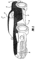
- exemplary body panels include a three-dimensionally contoured hood outer panel 23, a hood inner panel, front fenders 25, door outer panels 27, door inner panels, rear fenders 29, deck lid inner and outer panels, spoilers 31, a roof 33, and alternately, interior trim panels, smaller fuel filler doors, and exterior and interior garnish moldings.
- Hood 23 has outer surfaces 41 and 43 defined by multiple internal sheet layers 45 which are permanently affixed to each other during processing, and terminate at their peripheral edges 47. Peripheral edges 47 may be downwardly turned as shown, cut along generally vertical planes or provided with a partial radius by pinching then trimming.
- Outside surface 41 of composite hood product or part 23 is a class A exterior surface which must exhibit extremely high finish quality characteristics free of aesthetic blemishes and defects.
- a class A automotive vehicle surface is a smooth panel surface finish generally free of visible defects, blemishes, voids and tool marks, ideally suited for aesthetic viewing when installed on the vehicle.
- a first preferred embodiment of composite product 51 is shown in Figures 4-6.
- This embodiment employs a woven, carbon fiber, prepreg sheet 53 which, when coated, serves as the class A outside surface 41.
- the coating is optimally painted on using a clear coat for improving ultraviolet stability and gloss on the external face of first sheet 53.
- Woven sheet 53 has a visible, checkerboard-like pattern and is preferably obtained from Toray Composites (America), Inc., having a fiber format of T300S 3K, 2X2 twill fabric, with a G83C quick cure resin system, a fiber areal weight of about 380 g/m 2 , and a resin content of about 45%; it should be appreciated that alternate materials may be used.
- a veil or scrim sheet 55 is located immediately adjacent to exterior first sheet 53.
- Veil sheet 55 is a non-woven, short or medium strand, continuous fiberglass material, that has a multi-directional and random, overlapping fibrous orientation which allows for significant air permeability and flow in all of its directions; veil sheet 55 is preferably obtained from Hollinee Co. as the Surmat SF100 176A-5, A-1100 product, with a 5% 176A binder resin, 18 micron filament thickness, 20 mil thickness and 28 g/m 2 arial weight. Alternately, a veil from Regina Glass Fibre Pty. Ltd. of Australia or other materials employing similar processing characteristics, may be used.
- a third sheet 57 which is a prepreg material having generally unidirectional, carbon fibers therein is located immediately adjacent veil sheet 55.
- a fourth sheet 59 being of a generally unidirectional, carbon fiber, prepreg material, is disposed adjacent third unidirectional sheet 57.
- Fifth, sixth and seventh sheets of generally unidirectional, carbon fiber, prepreg material, 61, 63 and 65, respectively (and only partially shown in Figure 6) are respectively located adjacent fourth sheet 59 and each other in a stacked fashion.
- the fiber orientations are angularly offset between adjacent layers to improve uniform structural rigidity throughout the entire composite product. For example, if third sheet 57 has a 0° directional orientation of fibers then fourth sheet 59 preferably has a 90° orientation, fifth sheet 61 has a 0° orientation, sixth sheet 63 has a 90° orientation and seventh sheet 65 has a 0° orientation.
- the unidirectional, carbon fiber, prepreg material is preferably obtained from Toray Composites (America), Inc. as Part No. P3831C-190-1000, having a fiber format designation of T600S 24K, unidirectional, with a G83C quick cure resin system, a fiber areal weight of about 190 g/m 2 and a resin content of about 38%.
- a second preferred embodiment composite product 81 is essentially the same as the first preferred embodiment composite 51 except that a generally unidirectional, carbon fiber, prepreg material is used for first sheet 83 in this second embodiment.
- a veil sheet 85 and additional unidirectional, prepreg sheets 87, 89, 91, and possibly others, are stacked adjacent the external first sheet 83, but accounting for a fiber orientation offset between first and third sheets 83 and 87, respectively.
- the outside surface of first sheet 83 is preferably coated with an opaque and pigmented paint, such as to match the body color of the vehicle.
- a compression molding system 101 includes a vertically movable cavity tool 103 and a vertically stationary core tool 105 which are mounted to an automated press 107.
- a pair of cores 105 may be optionally mounted to a shuttle which will horizontally move one of the cores into the press for forming and curing while the other core is open for insertion loading of the pre-formed composite.
- the lay-up and molding locations preferably have a 30-40% relative humidity at 65-70 degrees Fahrenheit.
- an automated press having horizontally moving platens or tools can be used.
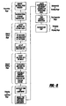
- the processing steps for the forming system are as follows:
- the core and cavity tools are preferably machined from aluminum but may alternately be steel, carbon fiber composite, ceramic or other materials sufficient for compression molding. It is also envisioned that a programmable Gerber cutting head or, alternately a steel rule die, can be used with the optional step 5 to cut multiple blanks for placement into the tool. Moreover, it is envisioned that one or more air vents are located at the periphery of the cavity tool. Approximately 200-300 psi of force are applied by the compression molding press, although lesser or greater forces can be applied.
- the veil sheet serves to outwardly move and channel air from the center of the part toward its peripheral edges during heating and compression in the mold.
- the resin from the adjacent prepreg sheets appears to flow through the thickness of the veil sheet in order to create a satisfactorily fully bonded composite structure.
- the compression molding and forming process of the present invention advantageously allows for overlapping edges of side-by-side (in the roll width direction) sheets, used when the standard roll width is too narrow than the desired final product, but without creating a thicker final composite part; this is unlike a traditional autoclave, vacuum bag and oven process which creates an undesirably thicker and potentially wrinkled part at the overlap in this situation.
- the number of unidirectional prepreg sheets can be varied in the laminate composite product depending upon the desired thickness and strength of the final composite product. For example, two, three, five or nine layers of unidirectional prepreg sheets may be used.
- the veil sheet is provided and located between every adjacent pair of prepreg sheets to further reduce and move trapped air from within the composite part. Additionally, it is alternately envisioned that the veil layer is employed with a vacuum bag and autoclave to reduce air and other gas voids within a composite part, although the majority of benefits achieved through the compression molding process of the present invention will not be realized.
- the composite product and forming system of the present invention is usable to create panels for airplanes, spacecraft, boats, motorcycle helmets, all terrain vehicles, and the like, although various advantages of the present invention's use with large, automotive vehicle panels may not be fully achieved.
- the prepreg layers may contain glass fiber, Kevlar fiber or a mixture of unidirectional, random or interwoven carbon, metallic, Kevlar and glass fibers.
- automated pressures also include a hydraulically driven and electromechanically driven press even if initially started with a manually moved lever or electronic controls. While various materials, temperatures and processing parameters have been disclosed, it should be appreciated that alternate materials, temperatures and processing parameters may be employed as long as the desired function and advantages are achieved. It is intended by the following claims to cover these and any other departures from the disclosed embodiments which fall within the true spirit of this invention.
Landscapes
- Engineering & Computer Science (AREA)
- Mechanical Engineering (AREA)
- Chemical & Material Sciences (AREA)
- Composite Materials (AREA)
- Textile Engineering (AREA)
- Casting Or Compression Moulding Of Plastics Or The Like (AREA)
- Moulding By Coating Moulds (AREA)
Abstract
A composite product (51) and forming method are provided. Multiple layers of fiber, prepreg sheets (53, 57, 59, 61, 63, 65) are employed with an internal air channeling sheet (55) to create a composite or laminate product. A further aspect of the present invention uses compression molding (103, 105) to form composite parts made from prepreg sheets. <IMAGE>
Description
The present invention relates generally to composite products and
forming systems for making such products and more particularly to create a
composite from fiber, prepreg layers.
Composite materials have been commonly employed in the aerospace
industry given the desirability for low weight, high strength and low thermal
expansion structures. Most such composites are made by hand laying up
multiple resin-impregnated fibrous layers, known as fiber prepregs, upon a
mandrel or form at room-temperature. A vacuum bag and autoclave are then
used to cure the composite in an oven. The typical autoclave and oven cycle
time is generally in the range of two-to-two and one half hours, not including the
time-consuming and expensive hand lay up process. Accordingly, such
processes are usually limited to very low volume part production. Examples of
traditional hand lay up, and autoclave and oven production methods are
disclosed in the following U.S. Patent Application Publication Nos.:
2004/0053027 entitled "Method for the Production of a Laminate and Bent
Product Consisting of Laminate" which was published to Labordus et al. on
March 18, 2004; 2004/0051214 entitled "Co-Cured Vacuum-Assisted Resin
Transfer Molding Manufacturing Method" which was published to Sheu et al. on
March 18, 2004; and 2002/0022422 entitled "Double Bag Vacuum and Fusion
Process and System for Low Cost, Advanced Composite Fabrication" which was
published to Waldrop, III, et al. on February 21, 2002.
Various unsuccessful experiments have been made to use pre-heated,
compression molds to form and cure large and contoured panels made from
multiple layers of unidirectional fiber and/or woven fiber prepreg materials.
Most, if not all, of these experimental panels exhibited unacceptable outside
surface distortion and imperfections due to trapped air remaining within the part
during molding. Such disadvantages are recognized for other attempts at
compression molding and autoclave processing of prepreg parts, for example in
the background section of U.S. Patent Application Publication No.
2003/0232176 entitled "Thermal Plastic Molding Process and Apparatus" which
was published to Polk, Jr., et al. on December 18, 2003,.
In accordance with the present invention, a composite product and
forming system are provided. In another aspect of the present invention,
multiple layers of fiber, prepreg sheets are employed with an internal air
channeling sheet to create a composite or laminate product. A further aspect of
the present invention uses compression molding to form composite parts made
from prepreg sheets. In yet another aspect of the present invention, carbon fiber
panels are produced without use of an autoclave, which are essentially free of
outside surface distortion caused by trapped air, which are used on automotive
vehicles requiring a high quality surface finish.
In particular, the invention provides a method of manufacturing a
laminate, the method comprising:
Preferred embodiments thereof comprises one or more of the following
features:
- at least one of the sheets is made of a woven carbon fiber, prepreg material;
- at least two of the sheets include carbon fiber and resin;
- at least an outer one of the sheets includes substantially unidirectional carbon fibers, the method further comprising applying a pigmented paint coating to the outer one sheet;
- creating a class A, automotive vehicle surface at an exposed surface of the sheets;
- compression molding the sheets together in a cycle time less than one hour and without requiring intermediate mold opening between a beginning and end of the compression molding cycle.
According to another aspect, the invention provides a method of making a
composite, the method comprising:
Preferred embodiments thereof comprises one or more of the following
features:
- the first sheet is made of a woven carbon fiber, prepreg material;
- applying a clear coating to at least one outside surface of the composite after molding;
- the first sheet is compressed directly by one of the tools, the tools being metallic;
- at least one of the first and third sheets include carbon fiber and resin;
- the first sheet includes substantially unidirectional carbon fibers, the method further comprising applying a pigmented paint coating to the first sheet after molding;
- creating a class A, automotive vehicle surface at the exposed surface of the first sheet;
- compression molding the sheets together in a cycle time less than one hour and without requiring intermediate tool opening between a beginning and end of the compression molding cycle, the tools comprising a pair of match metal dies of three-dimensional shape;
According to still another aspect, the invention provides a layered
composite part obtainable by or made in accorance with the method comprising:
Preferred embodiments thereof comprises one or more of the following
features:
- the molded sheets define an automotive vehicle, exterior body panel;
- the panel has a class A automotive vehicle surface;
- the first sheet is a woven carbon fiber, prepreg material;
- the composite part further comprises a clear coating located on an outside surface of the first sheet after molding such that a checkerboard-like pattern of the woven material is visible from outside the vehicle;
- at least one of the first and third sheets is a unidirectional carbon fiber prepreg material;
- both the first and third sheets are unidirectional fiber prepreg materials.
- the sheets are molded together without an auto clave and without a vacuum;
- the compression molding cycle time is less than one hour, the tools are closed during the entire molding cycle, and the tools include a metal cavity and a metal core.
According to still another aspect, the invention provides a panel
comprising:
- a first sheet including fiber and resin;
- a second sheet of fibrous veil material being air permeable and non-metallic; and
- a third sheet including fiber and resin, the first and third sheets sandwiching the second sheet in a stacked manner;
Preferred embodiments thereof comprises one or more of the following
features:
- the joined sheets define an automotive vehicle, exterior body panel;
- the first sheet has a class A automotive vehicle surface after joining;
- the first sheet is a woven carbon fiber, prepreg material;
- the panel further comprises a clear coating located on an outside surface of the first sheet such that a checkerboard-like pattern of a woven material is visible from outside the vehicle;
- at least one of the first and third sheets is a unidirectional carbon fiber prepreg material;
- both the first and third sheets are unidirectional fiber prepreg materials.
- the panel is formed by joining the sheets with the sheets being compression molded together without an auto clave and without a vacuum;
- the panel is formed by joining the sheets by compression molding in an automated press, a compression molding cycle time being less than one hour and a metal cavity and a metal core are closed during the entire molding cycle.
According to still another aspect, the invention provides a method of
manufacturing an automotive vehicle panel from a layered composite, the
method comprising:
the second sheet having different characteristics than the first, third and fourth sheets;
Preferred embodiments thereof comprises one or more of the following
features:
- the first sheet is made of a woven carbon fiber, prepreg material;
- applying a clear coating to at least one outside surface of the composite after molding;
- the first sheet is compressed directly by a cavity tool;
- the fourth sheet is compressed directly by a cavity tool;
- the veil material includes non-metallic fibers of random orientation which allow for significant air permeability and flow in all directions prior to molding;
- at least one of the first, third and fourth sheets include carbon fiber and resin;
- the first sheet includes substantially unidirectional carbon fibers, further comprising applying a paint coating to the first sheet after molding;
- creating a class A, automotive vehicle surface at an exposed surface of the first sheet;
- compression molding the sheets together in a cycle time less than one hour and without requiring intermediate mold opening between a beginning and end of the compression molding cycle, the tools comprising a pair of match metal dies of three-dimensional shape.
According to still another aspect, the invention provides a method of
manufacturing a layered composite part, the method comprising:
Preferred embodiments thereof comprises one or more of the following
features:
- directly compressing one of the sheets by the cavity;
- directly compressing another of the sheets by the core;
- place a veil material between at least one pair of the prepreg sheets prior to molding;
- at least one of the sheets is made of a woven carbon fiber, prepreg material;
- applying a clear coating to at least one outside surface of the composite part after molding;
- placing a veil material in the sandwich, wherein the veil material includes non-metallic fibers of varied orientation which allow for significant air permeability and flow in all directions prior to molding;
- at least two of the sheets include carbon fiber and resin;
- at least an outer one of the sheets includes substantially unidirectional carbon fibers, the method further comprising applying a pigmented paint coating to the outer one sheet;
- creating a class A, automotive vehicle surface at an exposed surface of the sheets;
- compression molding the sheets together in a cycle time less than one hour and without requiring intermediate mold opening between a beginning and end of the compression molding cycle.
According to still another aspect, the invention provides a method of
making an automotive vehicle panel from a layered composite, the method
comprising:
Preferred embodiments thereof comprises one or more of the following
features:
- the air permeable material is a sheet having randomly oriented glass fibers;
- at least one of the sheets is made of a woven carbon fiber, prepreg material;
- at least two of the sheets include carbon fiber and resin;
- at least an outer one of the sheets includes substantially unidirectional carbon fibers, the method further comprising applying a pigmented paint coating to the outer one sheet;
- creating a class A, automotive vehicle surface at an exposed surface of the sheets;
- compression molding the sheets together in a cycle time less than one hour and without requiring intermediate mold opening between a beginning and end of the compression molding cycle;
- the panel is a hood substantially free of trapped air voids adjacent an outer surface.
According to still another aspect, the invention provides an automotive
vehicle body panel comprising:
- a first sheet of fiber prepreg;
- a second sheet of material including randomly oriented fibers;
- a third sheet of fiber prepreg, the first and third sheets sandwiching the second sheet in stacked manner; and
- a fourth carbon fiber prepreg sheet stacked upon the third sheet, the third and fourth sheets including unidirectional carbon fibers oriented in offset directions from each other;
the first sheet defining a class A automotive vehicle surface substantially free of visible air voids.
Preferred embodiments thereof comprises one or more of the following
features:
- the first sheet is a woven carbon fiber, prepreg material;
- the panel further comprises a clear coating located on an outside surface of the first sheet such that a checkerboard-like pattern of a woven material is visible from outside the vehicle;
- both the first and third sheets are unidirectional carbon fiber prepreg materials;
- the sheets are compression molded together without an auto clave and without a vacuum;
- the sheets are joined by compression molding in an automated press, the compression molding cycle time is less than one, hour and a metal cavity and a metal core are closed during the entire molding cycle.
The composite product and forming system of the present invention are
advantageous over traditional products and methods of creating same since the
present invention parts can be produced in high volume, at relatively low cost,
and exhibit superior surface finish characteristics. The present invention
advantageously causes movement of undesirably trapped air or other gases
away from one or more exterior surfaces of the composite part and toward the
peripheral edges of the part. The cycle time of the present invention is
significantly faster than that achieved with conventional processes since a
vacuum bag and autoclave are not required. Structural integrity of the present
invention is also improved due to reduction of trapped air and voids in the
composite part. Additional advantages and features of the present invention
will become apparent from the following description and appended claims, taken
in conjunction with the accompanying drawings.
The composite product and forming system of the present invention is
preferably used to create large body panels in an automotive vehicle 21.
Referring to Figures 1-4, exemplary body panels include a three-dimensionally
contoured hood outer panel 23, a hood inner panel, front fenders 25, door outer
panels 27, door inner panels, rear fenders 29, deck lid inner and outer panels,
spoilers 31, a roof 33, and alternately, interior trim panels, smaller fuel filler
doors, and exterior and interior garnish moldings. Hood 23 has outer surfaces
41 and 43 defined by multiple internal sheet layers 45 which are permanently
affixed to each other during processing, and terminate at their peripheral edges
47. Peripheral edges 47 may be downwardly turned as shown, cut along
generally vertical planes or provided with a partial radius by pinching then
trimming. Outside surface 41 of composite hood product or part 23 is a class A
exterior surface which must exhibit extremely high finish quality characteristics
free of aesthetic blemishes and defects. Indeed, as is well known in the art, a
class A automotive vehicle surface is a smooth panel surface finish generally
free of visible defects, blemishes, voids and tool marks, ideally suited for
aesthetic viewing when installed on the vehicle.
A first preferred embodiment of composite product 51 is shown in Figures
4-6. This embodiment employs a woven, carbon fiber, prepreg sheet 53 which,
when coated, serves as the class A outside surface 41. The coating is optimally
painted on using a clear coat for improving ultraviolet stability and gloss on the
external face of first sheet 53. Woven sheet 53 has a visible, checkerboard-like
pattern and is preferably obtained from Toray Composites (America), Inc.,
having a fiber format of T300S 3K, 2X2 twill fabric, with a G83C quick cure resin
system, a fiber areal weight of about 380 g/m2, and a resin content of about
45%; it should be appreciated that alternate materials may be used. A veil or
scrim sheet 55 is located immediately adjacent to exterior first sheet 53. Veil
sheet 55 is a non-woven, short or medium strand, continuous fiberglass
material, that has a multi-directional and random, overlapping fibrous orientation
which allows for significant air permeability and flow in all of its directions; veil
sheet 55 is preferably obtained from Hollinee Co. as the Surmat SF100 176A-5,
A-1100 product, with a 5% 176A binder resin, 18 micron filament thickness, 20
mil thickness and 28 g/m2 arial weight. Alternately, a veil from Regina Glass
Fibre Pty. Ltd. of Australia or other materials employing similar processing
characteristics, may be used. A third sheet 57, which is a prepreg material
having generally unidirectional, carbon fibers therein is located immediately
adjacent veil sheet 55. A fourth sheet 59, being of a generally unidirectional,
carbon fiber, prepreg material, is disposed adjacent third unidirectional sheet 57.
Fifth, sixth and seventh sheets of generally unidirectional, carbon fiber, prepreg
material, 61, 63 and 65, respectively (and only partially shown in Figure 6) are
respectively located adjacent fourth sheet 59 and each other in a stacked
fashion. The fiber orientations are angularly offset between adjacent layers to
improve uniform structural rigidity throughout the entire composite product. For
example, if third sheet 57 has a 0° directional orientation of fibers then fourth
sheet 59 preferably has a 90° orientation, fifth sheet 61 has a 0° orientation,
sixth sheet 63 has a 90° orientation and seventh sheet 65 has a 0° orientation.
It is alternately envisioned that the angular orientations may vary depending
upon the specific part requirements; for example, alternating +/-45° layering may
be used for long and narrow parts, or alternating +60° and -30° layering may be
provided for hood inner panels and the like. The unidirectional, carbon fiber,
prepreg material is preferably obtained from Toray Composites (America), Inc.
as Part No. P3831C-190-1000, having a fiber format designation of T600S 24K,
unidirectional, with a G83C quick cure resin system, a fiber areal weight of about
190 g/m2 and a resin content of about 38%.
Referring to Figure 7, a second preferred embodiment composite product
81 is essentially the same as the first preferred embodiment composite 51
except that a generally unidirectional, carbon fiber, prepreg material is used for
first sheet 83 in this second embodiment. A veil sheet 85 and additional
unidirectional, prepreg sheets 87, 89, 91, and possibly others, are stacked
adjacent the external first sheet 83, but accounting for a fiber orientation offset
between first and third sheets 83 and 87, respectively. The outside surface of
first sheet 83 is preferably coated with an opaque and pigmented paint, such as
to match the body color of the vehicle.
The preferred processing and forming system of the present invention will
now be discussed with regard to both composite product embodiments, while
referring to Figures 5, 8 and 9. A compression molding system 101 includes a
vertically movable cavity tool 103 and a vertically stationary core tool 105 which
are mounted to an automated press 107. A pair of cores 105 may be optionally
mounted to a shuttle which will horizontally move one of the cores into the press
for forming and curing while the other core is open for insertion loading of the
pre-formed composite. The lay-up and molding locations preferably have a 30-40%
relative humidity at 65-70 degrees Fahrenheit. Alternately, an automated
press having horizontally moving platens or tools can be used. The processing
steps for the forming system are as follows:
The core and cavity tools are preferably machined from aluminum but
may alternately be steel, carbon fiber composite, ceramic or other materials
sufficient for compression molding. It is also envisioned that a programmable
Gerber cutting head or, alternately a steel rule die, can be used with the optional
step 5 to cut multiple blanks for placement into the tool. Moreover, it is
envisioned that one or more air vents are located at the periphery of the cavity
tool. Approximately 200-300 psi of force are applied by the compression
molding press, although lesser or greater forces can be applied.
It is believed that the veil sheet serves to outwardly move and channel air
from the center of the part toward its peripheral edges during heating and
compression in the mold. The resin from the adjacent prepreg sheets appears
to flow through the thickness of the veil sheet in order to create a satisfactorily
fully bonded composite structure. The compression molding and forming
process of the present invention advantageously allows for overlapping edges of
side-by-side (in the roll width direction) sheets, used when the standard roll
width is too narrow than the desired final product, but without creating a thicker
final composite part; this is unlike a traditional autoclave, vacuum bag and oven
process which creates an undesirably thicker and potentially wrinkled part at the
overlap in this situation.
It is alternately envisioned that the number of unidirectional prepreg
sheets can be varied in the laminate composite product depending upon the
desired thickness and strength of the final composite product. For example,
two, three, five or nine layers of unidirectional prepreg sheets may be used. In
another alternate embodiment, the veil sheet is provided and located between
every adjacent pair of prepreg sheets to further reduce and move trapped air
from within the composite part. Additionally, it is alternately envisioned that the
veil layer is employed with a vacuum bag and autoclave to reduce air and other
gas voids within a composite part, although the majority of benefits achieved
through the compression molding process of the present invention will not be
realized. In another alternate variation, the composite product and forming
system of the present invention is usable to create panels for airplanes,
spacecraft, boats, motorcycle helmets, all terrain vehicles, and the like, although
various advantages of the present invention's use with large, automotive vehicle
panels may not be fully achieved.
While various embodiments of the composite product and forming system
have been disclosed, it should be appreciated that variations may be made
without departing from the present invention. For example, the prepreg layers
may contain glass fiber, Kevlar fiber or a mixture of unidirectional, random or
interwoven carbon, metallic, Kevlar and glass fibers. As used herein, automated
pressures also include a hydraulically driven and electromechanically driven
press even if initially started with a manually moved lever or electronic controls.
While various materials, temperatures and processing parameters have been
disclosed, it should be appreciated that alternate materials, temperatures and
processing parameters may be employed as long as the desired function and
advantages are achieved. It is intended by the following claims to cover these
and any other departures from the disclosed embodiments which fall within the
true spirit of this invention.
Claims (32)
- A method of manufacturing a laminate, the method comprising:(a) placing an air permeable veil material (55; 85) between adjacent fibrous prepreg sheets (53, 57 ; 83, 87), the veil material including non-metallic fibers of varied orientation;(b) compressing the sheets and material together;(c) curing the sheets without an autoclave;(d) creating a rigid and three-dimensional part; and(e) moving trapped air toward peripheral edges of the laminate with the assistance of the veil material during compression and curing.
- The method of Claim 1 wherein at least one of the sheets (53) is made of a woven carbon fiber, prepreg material.
- The method of Claim 1 or 2 wherein at least two of the sheets include carbon fiber and resin.
- The method of any one of Claims 1 to 3 wherein at least an outer one of the sheets includes substantially unidirectional carbon fibers, the method further comprising applying a pigmented paint coating to the outer one sheet.
- The method of any one of Claims 1 to 4 further comprising creating a class A, automotive vehicle surface (41) at an exposed surface of the sheets.
- The method of any one of Claims 1 to 5 further comprising compression molding the sheets together in a cycle time less than one hour and without requiring intermediate mold opening between a beginning and end of the compression molding cycle.
- A method of making a composite (51; 81), the method comprising:(a) locating a first sheet (53; 83) of fiber prepreg at a position;(b) locating a second sheet (55; 85) of a randomly oriented and air permeable material at the position in a stacked relationship to the first sheet;(c) locating a third sheet (57; 87) of fiber prepreg at the position in a stacked relationship to the second sheet;(d) compression molding the sheets together between preheated tools (103, 105) in an automated press; and(e) moving trapped air toward peripheral edges of the composite, with the assistance of the second sheet, during molding.
- The method of Claim 1 wherein the first sheet (53) is made of a woven carbon fiber, prepreg material.
- The method of Claim 7 or 8 further comprising applying a clear coating to at least one outside surface of the composite after molding.
- The method of any one of Claims 7 to 9 wherein the first sheet is compressed directly by one of the tools, the tools being metallic.
- The method of any one of Claims 7 to 10 wherein at least one of the first and third sheets include carbon fiber and resin.
- The method of any one of Claims 7 to 11 wherein the first sheet includes substantially unidirectional carbon fibers (83), the method further comprising applying a pigmented paint coating to the first sheet after molding.
- The method of any one of Claims 7 to 12 further comprising creating a class A, automotive vehicle surface (41) at the exposed surface of the first sheet.
- The method of any one of Claims 7 to 13 further comprising compression molding the sheets together in a cycle time less than one hour and without requiring intermediate tool opening between a beginning and end of the compression molding cycle, the tools (103, 105) comprising a pair of match metal dies of three-dimensional shape.
- A layered composite part obtainable by the method comprising:(a) locating a first sheet (53; 83) of fiber prepreg at a position;(b) locating a second sheet (55) of a randomly oriented and air permeable material at the position in a stacked relationship to the first sheet;(c) locating a third sheet (57) of fiber prepreg at the position in a stacked relationship to the second sheet;(d) compression molding the sheets together between preheated tools (103, 105); and(e) moving trapped air toward peripheral edges of the composite, with the assistance of the second sheet, during molding.
- The composite part of Claim 15 wherein the molded sheets define an automotive vehicle, exterior body panel.
- The composite part of Claim 15 or 16 wherein the panel has a class A automotive vehicle surface (41).
- The composite part of any one of Claims 15 to 17 wherein the first sheet (53) is a woven carbon fiber, prepreg material.
- The composite part of any one of Claims 16 to 18 further comprising a clear coating located on an outside surface of the first sheet after molding such that a checkerboard-like pattern of the woven material is visible from outside the vehicle.
- The composite part of any one of Claims 15 to 19 wherein at least one of the first and third sheets (57; 83, 87) is a unidirectional carbon fiber prepreg material.
- The composite part of Claim 20 wherein both the first and third sheets (83, 87) are unidirectional fiber prepreg materials.
- The composite part of any one of Claims 15 to 21 wherein the sheets are molded together without an auto clave and without a vacuum.
- The composite part of any one of Claims 15 to 22 wherein the compression molding cycle time is less than one hour, the tools are closed during the entire molding cycle, and the tools include a metal cavity and a metal core.
- A panel comprising:wherein the panel is formed by joining the sheets with the second sheet allowing trapped air to move toward peripheral edges of the panel during joining of the sheets.a first sheet (53; 83) including fiber and resin;a second sheet (55; 85) of fibrous veil material being air permeable and non-metallic; anda third sheet (57; 87) including fiber and resin, the first and third sheets sandwiching the second sheet in a stacked manner;
- The panel of Claim 24 wherein the joined sheets define an automotive vehicle, exterior body panel.
- The panel of Claim 24 or 25 wherein the first sheet has a class A automotive vehicle surface (41) after joining.
- The panel of any one of Claim 24 to 26 wherein the first sheet (53) is a woven carbon fiber, prepreg material.
- The panel of any one of Claims 25 to 27 further comprising a clear coating located on an outside surface of the first sheet such that a checkerboard-like pattern of a woven material is visible from outside the vehicle.
- The panel of any one of Claims 24 to 28 wherein at least one of the first and third sheets (57; 83, 87) is a unidirectional carbon fiber prepreg material.
- The panel of Claim 29 wherein both the first and third sheets (83, 87) are unidirectional fiber prepreg materials.
- The panel of any one of Claims 24 to 30 wherein the panel is formed by joining the sheets with the sheets being compression molded together without an auto clave and without a vacuum.
- The panel of any one of Claims 24 to 31 wherein the panel is formed by joining the sheets by compression molding in an automated press, a compression molding cycle time being less than one hour and a metal cavity and a metal core are closed during the entire molding cycle.
Applications Claiming Priority (4)
| Application Number | Priority Date | Filing Date | Title |
|---|---|---|---|
| US565255 | 1990-08-09 | ||
| US56525504P | 2004-04-23 | 2004-04-23 | |
| US11/017,242 US20050236736A1 (en) | 2004-04-23 | 2004-12-20 | Composite product and forming system |
| US17242 | 2004-12-20 |
Publications (1)
| Publication Number | Publication Date |
|---|---|
| EP1588838A1 true EP1588838A1 (en) | 2005-10-26 |
Family
ID=34942188
Family Applications (1)
| Application Number | Title | Priority Date | Filing Date |
|---|---|---|---|
| EP05290892A Withdrawn EP1588838A1 (en) | 2004-04-23 | 2005-04-22 | Composite product and forming system |
Country Status (4)
| Country | Link |
|---|---|
| US (1) | US20050236736A1 (en) |
| EP (1) | EP1588838A1 (en) |
| JP (1) | JP2005306039A (en) |
| CA (1) | CA2504072A1 (en) |
Cited By (14)
| Publication number | Priority date | Publication date | Assignee | Title |
|---|---|---|---|---|
| EP1920913A1 (en) * | 2006-11-06 | 2008-05-14 | Per Aarsleff A/S | A lining assembly, a lining tube, a composite lining assembly and a solidified lining tube |
| EP1920912A1 (en) * | 2006-11-06 | 2008-05-14 | Per Aarsleff A/S | A lining assembly for a tube |
| DE102008007879A1 (en) * | 2008-02-06 | 2009-08-13 | Edag Gmbh & Co. Kgaa | Carbon fiber composite part for the automotive industry, comprises synthetic resin-laminated carbon fiber fabric, and laminated semi-finished material, which has carbon fiber compound, forms visible surface and comprises polyurethane-layer |
| DE102008014657A1 (en) * | 2008-03-17 | 2009-09-24 | Eads Deutschland Gmbh | Process for the production of fiber composite components |
| WO2010083980A1 (en) * | 2009-01-26 | 2010-07-29 | Daimler Ag | Composite component having cover layer |
| EP2535170A1 (en) | 2011-06-16 | 2012-12-19 | Deutsches Zentrum für Luft- und Raumfahrt e.V. | Method for producing coloured fibre compound components and commercial vehicle comprising these components |
| DE102012003001A1 (en) * | 2012-02-15 | 2013-08-22 | Bayerische Motoren Werke Aktiengesellschaft | Method for manufacturing fiber composite, particularly carbon fiber composite component for use in automotive industry, involves cutting fiber semi-finished part to form fiber layers with predetermined dimensions |
| DE102013002364A1 (en) * | 2013-02-09 | 2014-08-14 | Daimler Ag | Fiber-reinforced vision component of motor vehicle, has outer layer arranged in visible, and load bearing layer having predetermined fiber orientation with strength parameters resilient than damping layer |
| CN104520173A (en) * | 2013-06-26 | 2015-04-15 | 康廷南拓结构塑料有限公司 | Two-Piece Bonded Vehicle Components |
| WO2016102415A1 (en) * | 2014-12-23 | 2016-06-30 | Hexcel Composites Limited | Moulding materials with improved surface finish |
| CN108367509A (en) * | 2015-12-14 | 2018-08-03 | 麦格纳外饰公司 | Impregnate veil |
| US10065393B2 (en) | 2006-03-25 | 2018-09-04 | Hexcel Composites Limited | Structured thermoplastic in composite interleaves |
| US10618227B2 (en) | 2006-03-25 | 2020-04-14 | Hexcel Composites, Ltd. | Structured thermoplastic in composite interleaves |
| EP4223489A1 (en) * | 2017-02-06 | 2023-08-09 | Short Brothers Plc | Aircraft electrical isolation component and method of manufacturing electrical isolation component |
Families Citing this family (14)
| Publication number | Priority date | Publication date | Assignee | Title |
|---|---|---|---|---|
| WO2008013233A1 (en) | 2006-07-27 | 2008-01-31 | The University Of Tokyo | Multilayer steel and method for producing multilayer steel |
| US7807258B2 (en) * | 2006-09-22 | 2010-10-05 | Board Of Trustees Of Michigan State University | Topologically controlled composite structure |
| DE102007003275B4 (en) * | 2007-01-23 | 2013-11-28 | Airbus Operations Gmbh | Shell element as part of an aircraft fuselage |
| US9802369B2 (en) * | 2008-03-14 | 2017-10-31 | Bauer Hockey, Llc | Epoxy core with expandable microspheres |
| US7824591B2 (en) | 2008-03-14 | 2010-11-02 | Bauer Hockey, Inc. | Method of forming hockey blade with wrapped, stitched core |
| KR101139361B1 (en) * | 2009-11-27 | 2012-04-26 | 한국신발피혁연구소 | Vacuum bagging molding method for removing porosity on surface and delamination between layers of fiber in composite material |
| US8677599B2 (en) | 2010-09-20 | 2014-03-25 | Bauer Hockey, Inc. | Blade constructs and methods of forming blade constructs |
| BR112015014928B1 (en) * | 2012-12-21 | 2021-03-30 | Cytec Industries Inc. | CURABLE COMPOSITE MATERIAL AND METHODS FOR MANUFACTURING A CURABLE COMPOSITE MATERIAL AND FOR MANUFACTURING A CURABLE COMPOSITE PIECE |
| CN107471681A (en) | 2017-08-25 | 2017-12-15 | 中信戴卡股份有限公司 | A kind of part for the method for composite material component surface treatment and through processing |
| CN107474290A (en) * | 2017-08-25 | 2017-12-15 | 中信戴卡股份有限公司 | A kind of method for Treatment of Carbon composite material surface |
| CA3163830A1 (en) * | 2019-01-11 | 2020-07-16 | Carlos Jose AVALOS SARTORIO | Carbon fiber shell having elastomer inner overmold, and method to fabricate a carbon fiber shell having elastomer inner overmold |
| DE102020119196A1 (en) * | 2020-07-21 | 2022-01-27 | Bayerische Motoren Werke Aktiengesellschaft | Outer skin component for a motor vehicle and method for producing an outer skin component |
| CN114932693B (en) * | 2022-06-14 | 2023-07-28 | 中复神鹰(上海)科技有限公司 | Preparation method of carbon fiber composite laminated board with high open-pore tensile strength |
| US20250083403A1 (en) * | 2023-09-07 | 2025-03-13 | Teijin Automotive Technologies, Inc. | In mold painting of lightweight core structure assembly with vehicle exterior surface finish |
Citations (9)
| Publication number | Priority date | Publication date | Assignee | Title |
|---|---|---|---|---|
| US5104718A (en) * | 1989-02-28 | 1992-04-14 | Mitsubishi Rayon Co., Ltd. | Prepreg and process for producing the same |
| WO2000027632A1 (en) * | 1998-11-06 | 2000-05-18 | Structural Polymer Systems Limited | Moulding materials |
| WO2002028624A1 (en) * | 2000-10-03 | 2002-04-11 | Structural Polymer Systems Limited | Sheet moulding compound (smc) with ventilating structure for entrapped gases |
| WO2002090089A1 (en) * | 2001-05-09 | 2002-11-14 | Structural Polymer Systems Limited | Moulding material with ventilating structure for entrapped gases |
| WO2002094564A1 (en) * | 2001-05-23 | 2002-11-28 | Structural Polymer Systems Limited | Surface material comprising a surface resin material and a resin conducting layer |
| US20030000081A1 (en) * | 1997-06-13 | 2003-01-02 | International Business Machines Corporation | Method for reducing coefficient of thermal expansion in chip attach packages |
| EP1321282A1 (en) * | 2001-12-20 | 2003-06-25 | epo GmbH | Prepreg |
| WO2004009314A1 (en) * | 2002-07-18 | 2004-01-29 | Mitsubishi Rayon Co., Ltd. | Prepreg, intermediate material for forming frp, and method for production thereof and method for production of fiber-reinforced composite material |
| EP1524106A1 (en) * | 2003-10-14 | 2005-04-20 | Saab Ab | Method of forming a composite structure |
Family Cites Families (47)
| Publication number | Priority date | Publication date | Assignee | Title |
|---|---|---|---|---|
| US3035310A (en) * | 1956-01-23 | 1962-05-22 | Republic Aviat Corp | Method of making reinforced synthetic resin forming tool |
| US3907960A (en) * | 1972-11-01 | 1975-09-23 | United Technologies Corp | Method for producing a substantially voidless filament reinforced resin matrix composite |
| US3889035A (en) * | 1972-11-27 | 1975-06-10 | Marling Ind Limited | Fiber-reinforced plastic articles |
| SE7602629L (en) * | 1975-03-03 | 1976-09-06 | Monsanto Co | LAYERED FABRICS AND PROCEDURES FOR THEIR MANUFACTURE |
| US4081582A (en) * | 1976-10-20 | 1978-03-28 | Johnson & Johnson | Fibrous material and method of making the same |
| US4201247A (en) * | 1977-06-29 | 1980-05-06 | Owens-Corning Fiberglas Corporation | Fibrous product and method and apparatus for producing same |
| DE3109424A1 (en) * | 1981-03-12 | 1982-10-28 | Herbert 7140 Ludwigsburg Schreiber | METHOD FOR THE PRODUCTION OF FIBER REINFORCED PLASTIC OBJECTS AND PREPREG FOR ITS IMPLEMENTATION AND ITEMS OBTAINED THEREOF |
| GB2173144B (en) * | 1985-04-02 | 1989-08-09 | Rolls Royce Plc | Moulding of composite materials |
| US4810444A (en) * | 1987-06-08 | 1989-03-07 | The Dow Chemical Company | Method for making mat-molded rim parts |
| US4950439A (en) * | 1987-07-10 | 1990-08-21 | C. H. Masland & Sons | Glossy finish fiber reinforced molded product |
| US5023041A (en) * | 1987-12-10 | 1991-06-11 | General Electric Company | Method for making a fiber reinforced composite article |
| US5641366A (en) * | 1988-01-20 | 1997-06-24 | Loral Vought Systems Corporation | Method for forming fiber-reinforced composite |
| US5004765A (en) * | 1988-03-31 | 1991-04-02 | Union Carbide Chemicals & Plastics Technology Corporation | Low profile molding system |
| JP2732131B2 (en) * | 1988-10-27 | 1998-03-25 | 横浜ゴム株式会社 | Golf club head and method of manufacturing the same |
| US5286553A (en) * | 1988-12-15 | 1994-02-15 | Asahi Kasei Kogyo Kabushiki Kaisha | Composite sheet for fibrous reinforcing material |
| US5171630A (en) * | 1989-04-17 | 1992-12-15 | Georgia Tech Research Corporation | Flexible multiply towpreg |
| US4983442A (en) * | 1990-07-13 | 1991-01-08 | United Technologies Automotive Inc. | Composite article and method of making same |
| US6585839B2 (en) * | 1991-03-01 | 2003-07-01 | Foster-Miller, Inc. | Method of fabricating a polymer-matrix fiber-reinforced composite and the product thereof |
| JP2593772B2 (en) * | 1992-09-01 | 1997-03-26 | 川崎重工業株式会社 | Manufacturing method for composite products |
| US6027794A (en) * | 1993-01-14 | 2000-02-22 | Toray Industries, Inc. | Prepregs, processes for their production, and composite laminates |
| US5401564A (en) * | 1993-03-23 | 1995-03-28 | Hexcel Corporation | Materials and processes for fabricating formed composite articles and use in shoe arch |
| JP3505754B2 (en) * | 1993-12-02 | 2004-03-15 | 東レ株式会社 | Prepreg and manufacturing method thereof |
| US5857215A (en) * | 1994-07-01 | 1999-01-12 | Ilixco, Inc. | Helmet with high performance head and face protection utilizing molded composite materials and method |
| US5565162A (en) * | 1994-09-30 | 1996-10-15 | Composite Manufacturing & Research Inc. | Method for manufacturing a fiber reinforced composite article |
| US6238506B1 (en) * | 1996-01-26 | 2001-05-29 | Toho Rayon Co., Ltd. | Method of manufacturing steering wheel |
| JP3529009B2 (en) * | 1996-10-14 | 2004-05-24 | 新日本石油株式会社 | Carbon fiber reinforced composite |
| US5827608A (en) * | 1996-10-28 | 1998-10-27 | Minnesota Mining And Manufacturing Company | Method of forming a thermoplastic layer on a flexible two-dimensional substrate and powder for preparing same |
| JP3774959B2 (en) * | 1996-11-06 | 2006-05-17 | 東レ株式会社 | Molding material and manufacturing method thereof |
| KR100189169B1 (en) * | 1996-11-27 | 1999-06-01 | 윤덕용 | Carbon Fiber Reinforced Composites with Morphology Gradient |
| US6048488A (en) * | 1997-04-04 | 2000-04-11 | The United States Of America As Represented By The Secretary Of The Army | One-step resin transfer molding of multifunctional composites consisting of multiple resins |
| US5911932A (en) * | 1997-07-09 | 1999-06-15 | R. Charles Balmer | Method of prepregging with resin |
| US6869558B2 (en) * | 1997-12-18 | 2005-03-22 | Thermoplastic Composite Designs, Inc. | Thermoplastic molding process and apparatus |
| US5968445A (en) * | 1998-01-05 | 1999-10-19 | The Boeing Company | Method and apparatus for curing large composite panels |
| DE69913737T3 (en) * | 1998-05-20 | 2009-05-14 | Cytec Technology Corp., Wilmington | Preparation of bubble-free laminates and use of same |
| WO1999064216A1 (en) * | 1998-06-08 | 1999-12-16 | Complastik Corporation | Composite articles including prepregs, preforms, laminates and sandwich moldings, and methods of making the same |
| US6241506B1 (en) * | 1998-09-29 | 2001-06-05 | Alliant Techsystems Inc. | Compression mold |
| US6670028B2 (en) * | 1999-05-26 | 2003-12-30 | University Of Massachusetts | Molded article and process for preparing same |
| DE19932274A1 (en) * | 1999-07-05 | 2001-01-18 | Inst Polymerforschung Dresden | Fiber composite material and process for its manufacture |
| FR2798356B1 (en) * | 1999-09-09 | 2001-10-26 | Lorraine Laminage | REINFORCED AND LIGHTWEIGHT AUTOMOBILE HOOD |
| WO2001041993A2 (en) * | 1999-12-07 | 2001-06-14 | The Boeing Company | Double bag vacuum infusion process and system for low cost, advanced composite fabrication |
| US6568495B1 (en) * | 2000-08-02 | 2003-05-27 | Asc Incorporated | Automotive vehicle hood system |
| WO2002018127A1 (en) * | 2000-08-28 | 2002-03-07 | Sakase Adtech Co., Ltd. | Composite material, formed product, and prepreg |
| AU2002241584A1 (en) * | 2000-12-06 | 2002-06-18 | Complastik Corporation | Hybrid composite articles and methods for their production |
| US20030082385A1 (en) * | 2001-07-13 | 2003-05-01 | Toray Composites (America), Inc. | Quick cure carbon fiber reinforced epoxy resin |
| US7087296B2 (en) * | 2001-11-29 | 2006-08-08 | Saint-Gobain Technical Fabrics Canada, Ltd. | Energy absorbent laminate |
| NL1019601C2 (en) * | 2001-12-18 | 2003-06-30 | Fokker Aerostructures Bv | Method for manufacturing a laminate as well as curved product consisting of laminate. |
| US7419627B2 (en) * | 2002-09-13 | 2008-09-02 | Northrop Grumman Corporation | Co-cured vacuum-assisted resin transfer molding manufacturing method |
-
2004
- 2004-12-20 US US11/017,242 patent/US20050236736A1/en not_active Abandoned
-
2005
- 2005-04-13 CA CA002504072A patent/CA2504072A1/en not_active Abandoned
- 2005-04-22 EP EP05290892A patent/EP1588838A1/en not_active Withdrawn
- 2005-04-25 JP JP2005126765A patent/JP2005306039A/en active Pending
Patent Citations (10)
| Publication number | Priority date | Publication date | Assignee | Title |
|---|---|---|---|---|
| US5104718A (en) * | 1989-02-28 | 1992-04-14 | Mitsubishi Rayon Co., Ltd. | Prepreg and process for producing the same |
| US20030000081A1 (en) * | 1997-06-13 | 2003-01-02 | International Business Machines Corporation | Method for reducing coefficient of thermal expansion in chip attach packages |
| WO2000027632A1 (en) * | 1998-11-06 | 2000-05-18 | Structural Polymer Systems Limited | Moulding materials |
| WO2002028624A1 (en) * | 2000-10-03 | 2002-04-11 | Structural Polymer Systems Limited | Sheet moulding compound (smc) with ventilating structure for entrapped gases |
| WO2002090089A1 (en) * | 2001-05-09 | 2002-11-14 | Structural Polymer Systems Limited | Moulding material with ventilating structure for entrapped gases |
| WO2002094564A1 (en) * | 2001-05-23 | 2002-11-28 | Structural Polymer Systems Limited | Surface material comprising a surface resin material and a resin conducting layer |
| EP1321282A1 (en) * | 2001-12-20 | 2003-06-25 | epo GmbH | Prepreg |
| WO2004009314A1 (en) * | 2002-07-18 | 2004-01-29 | Mitsubishi Rayon Co., Ltd. | Prepreg, intermediate material for forming frp, and method for production thereof and method for production of fiber-reinforced composite material |
| EP1541312A1 (en) * | 2002-07-18 | 2005-06-15 | Mitsubishi Rayon Co., Ltd. | Prepreg, intermediate material for forming frp, and method for production thereof and method for production of fiber-reinforced composite material |
| EP1524106A1 (en) * | 2003-10-14 | 2005-04-20 | Saab Ab | Method of forming a composite structure |
Cited By (22)
| Publication number | Priority date | Publication date | Assignee | Title |
|---|---|---|---|---|
| US10065393B2 (en) | 2006-03-25 | 2018-09-04 | Hexcel Composites Limited | Structured thermoplastic in composite interleaves |
| US10618227B2 (en) | 2006-03-25 | 2020-04-14 | Hexcel Composites, Ltd. | Structured thermoplastic in composite interleaves |
| EP1920913A1 (en) * | 2006-11-06 | 2008-05-14 | Per Aarsleff A/S | A lining assembly, a lining tube, a composite lining assembly and a solidified lining tube |
| EP1920912A1 (en) * | 2006-11-06 | 2008-05-14 | Per Aarsleff A/S | A lining assembly for a tube |
| DE102008007879A1 (en) * | 2008-02-06 | 2009-08-13 | Edag Gmbh & Co. Kgaa | Carbon fiber composite part for the automotive industry, comprises synthetic resin-laminated carbon fiber fabric, and laminated semi-finished material, which has carbon fiber compound, forms visible surface and comprises polyurethane-layer |
| DE102008007879B4 (en) * | 2008-02-06 | 2009-11-26 | Edag Gmbh & Co. Kgaa | Carbon fiber composite component |
| US8398795B2 (en) | 2008-03-17 | 2013-03-19 | Eads Deutschland Gmbh | Method for producing a fiber connection component |
| DE102008014657B4 (en) * | 2008-03-17 | 2015-08-20 | Airbus Defence and Space GmbH | Process for the production of fiber composite components |
| DE102008014657A1 (en) * | 2008-03-17 | 2009-09-24 | Eads Deutschland Gmbh | Process for the production of fiber composite components |
| EP2382086A1 (en) * | 2009-01-26 | 2011-11-02 | Daimler AG | Composite component having cover layer |
| WO2010083980A1 (en) * | 2009-01-26 | 2010-07-29 | Daimler Ag | Composite component having cover layer |
| EP2535170A1 (en) | 2011-06-16 | 2012-12-19 | Deutsches Zentrum für Luft- und Raumfahrt e.V. | Method for producing coloured fibre compound components and commercial vehicle comprising these components |
| DE102011051099A1 (en) * | 2011-06-16 | 2012-12-20 | Deutsches Zentrum für Luft- und Raumfahrt e.V. | Airliner with and method of making dyed fiber composite components |
| DE102012003001A1 (en) * | 2012-02-15 | 2013-08-22 | Bayerische Motoren Werke Aktiengesellschaft | Method for manufacturing fiber composite, particularly carbon fiber composite component for use in automotive industry, involves cutting fiber semi-finished part to form fiber layers with predetermined dimensions |
| DE102013002364A1 (en) * | 2013-02-09 | 2014-08-14 | Daimler Ag | Fiber-reinforced vision component of motor vehicle, has outer layer arranged in visible, and load bearing layer having predetermined fiber orientation with strength parameters resilient than damping layer |
| CN104520173A (en) * | 2013-06-26 | 2015-04-15 | 康廷南拓结构塑料有限公司 | Two-Piece Bonded Vehicle Components |
| CN110843928A (en) * | 2013-06-26 | 2020-02-28 | 康廷南拓结构塑料有限公司 | Two-piece cementitious vehicle component |
| WO2016102415A1 (en) * | 2014-12-23 | 2016-06-30 | Hexcel Composites Limited | Moulding materials with improved surface finish |
| GB2566000A (en) * | 2014-12-23 | 2019-03-06 | Hexcel Composites Ltd | Moulding materials with improved surface finish |
| CN108367509A (en) * | 2015-12-14 | 2018-08-03 | 麦格纳外饰公司 | Impregnate veil |
| US11440272B2 (en) | 2015-12-14 | 2022-09-13 | Magna Exteriors Inc. | Impregnated veils |
| EP4223489A1 (en) * | 2017-02-06 | 2023-08-09 | Short Brothers Plc | Aircraft electrical isolation component and method of manufacturing electrical isolation component |
Also Published As
| Publication number | Publication date |
|---|---|
| CA2504072A1 (en) | 2005-10-23 |
| JP2005306039A (en) | 2005-11-04 |
| US20050236736A1 (en) | 2005-10-27 |
Similar Documents
| Publication | Publication Date | Title |
|---|---|---|
| US20050236736A1 (en) | Composite product and forming system | |
| US20050255311A1 (en) | Hybrid composite product and system | |
| EP3711933B1 (en) | Method and system for co-consolidation of thermoplastic composite material parts | |
| Karlsson et al. | Manufacturing and applications of structural sandwich components | |
| EP1755854B1 (en) | Method and mold for manufacturing decorative components for motor vehicle interiors | |
| EP1773587B1 (en) | Recyclable composite plastic and related manufacturing methods | |
| US5252160A (en) | Method of manufacturing a metal/composite spinner cone | |
| JP7434432B2 (en) | Composite material inlays in additively manufactured structures | |
| US20120021196A1 (en) | Smooth composite structure | |
| US20050242626A1 (en) | Reinforced composite inner roof panel of the cellular core sandwich-type and method of making same | |
| EP1972426B1 (en) | Method and tools for producing ring frames from a composite material | |
| WO2005105413A2 (en) | Automated forming of pre-impregnated composite structural elements | |
| DE102008009438A1 (en) | Formed part producing method, involves forming cut surface foil according to topography of formed part, applying woven fabric and resin in cutting tool on inside of foil, and taking out finished part after precipitation hardening to tool | |
| US6702964B2 (en) | Method of making a flat composite body with an asymmetric laminar structure | |
| US20200148278A1 (en) | Vehicle External Surface Component and Method for Producing a Vehicle External Surface Component | |
| EP1649999A2 (en) | Process for producing a form stable object with a flat textile surface, particularly with a fiber reinforced composite coating | |
| US20120231244A1 (en) | Flat Composite Component, in Particular a Vehicle Body Part | |
| US20190389107A1 (en) | Vehicle outer surface component and method for producing a vehicle outer surface component | |
| US20190143611A1 (en) | Laminated Moulded Parts and Manufacture Thereof | |
| US20170334154A1 (en) | Laminated Moulded Parts and Manufacture Thereof | |
| CN208630040U (en) | A kind of lightweight multilayer materials heavy truck door trim panel | |
| US20030001318A1 (en) | Method of making sandwich construction thermoplastic panels for automotive interior trim using sheet extrusion | |
| CA2775672C (en) | Metal-skinned composite vehicle body panel | |
| JP2003053865A (en) | Manufacturing method of honeycomb sandwich panel | |
| EP1944156A1 (en) | A thermoformable layered material and the production process thereof |
Legal Events
| Date | Code | Title | Description |
|---|---|---|---|
| PUAI | Public reference made under article 153(3) epc to a published international application that has entered the european phase |
Free format text: ORIGINAL CODE: 0009012 |
|
| AK | Designated contracting states |
Kind code of ref document: A1 Designated state(s): AT BE BG CH CY CZ DE DK EE ES FI FR GB GR HU IE IS IT LI LT LU MC NL PL PT RO SE SI SK TR |
|
| AX | Request for extension of the european patent |
Extension state: AL BA HR LV MK YU |
|
| 17P | Request for examination filed |
Effective date: 20060426 |
|
| AKX | Designation fees paid |
Designated state(s): DE FR GB IT SE |
|
| STAA | Information on the status of an ep patent application or granted ep patent |
Free format text: STATUS: THE APPLICATION IS DEEMED TO BE WITHDRAWN |
|
| 18D | Application deemed to be withdrawn |
Effective date: 20071031 |