EP1588832A1 - Device of forming tire reinforcing layer - Google Patents
Device of forming tire reinforcing layer Download PDFInfo
- Publication number
- EP1588832A1 EP1588832A1 EP04704338A EP04704338A EP1588832A1 EP 1588832 A1 EP1588832 A1 EP 1588832A1 EP 04704338 A EP04704338 A EP 04704338A EP 04704338 A EP04704338 A EP 04704338A EP 1588832 A1 EP1588832 A1 EP 1588832A1
- Authority
- EP
- European Patent Office
- Prior art keywords
- drum
- conveying path
- reinforcing material
- moving
- reinforcing layer
- Prior art date
- Legal status (The legal status is an assumption and is not a legal conclusion. Google has not performed a legal analysis and makes no representation as to the accuracy of the status listed.)
- Granted
Links
Images


Classifications
-
- B—PERFORMING OPERATIONS; TRANSPORTING
- B29—WORKING OF PLASTICS; WORKING OF SUBSTANCES IN A PLASTIC STATE IN GENERAL
- B29D—PRODUCING PARTICULAR ARTICLES FROM PLASTICS OR FROM SUBSTANCES IN A PLASTIC STATE
- B29D30/00—Producing pneumatic or solid tyres or parts thereof
- B29D30/06—Pneumatic tyres or parts thereof (e.g. produced by casting, moulding, compression moulding, injection moulding, centrifugal casting)
- B29D30/08—Building tyres
- B29D30/20—Building tyres by the flat-tyre method, i.e. building on cylindrical drums
- B29D30/30—Applying the layers; Guiding or stretching the layers during application
- B29D30/3057—Applying the layers; Guiding or stretching the layers during application by feeding cut-to-length pieces in a direction inclined with respect to the drum axis and placing the pieces side-by-side to form an annular element
-
- B—PERFORMING OPERATIONS; TRANSPORTING
- B29—WORKING OF PLASTICS; WORKING OF SUBSTANCES IN A PLASTIC STATE IN GENERAL
- B29D—PRODUCING PARTICULAR ARTICLES FROM PLASTICS OR FROM SUBSTANCES IN A PLASTIC STATE
- B29D30/00—Producing pneumatic or solid tyres or parts thereof
- B29D30/06—Pneumatic tyres or parts thereof (e.g. produced by casting, moulding, compression moulding, injection moulding, centrifugal casting)
- B29D30/08—Building tyres
- B29D30/10—Building tyres on round cores, i.e. the shape of the core is approximately identical with the shape of the completed tyre
- B29D30/16—Applying the layers; Guiding or stretching the layers during application
- B29D30/1657—Applying the layers; Guiding or stretching the layers during application by feeding cut-to-length pieces in a direction inclined with respect to the core axis and placing the pieces side-by-side to form an annular element
-
- B—PERFORMING OPERATIONS; TRANSPORTING
- B29—WORKING OF PLASTICS; WORKING OF SUBSTANCES IN A PLASTIC STATE IN GENERAL
- B29D—PRODUCING PARTICULAR ARTICLES FROM PLASTICS OR FROM SUBSTANCES IN A PLASTIC STATE
- B29D30/00—Producing pneumatic or solid tyres or parts thereof
- B29D30/06—Pneumatic tyres or parts thereof (e.g. produced by casting, moulding, compression moulding, injection moulding, centrifugal casting)
- B29D30/70—Annular breakers
-
- B—PERFORMING OPERATIONS; TRANSPORTING
- B29—WORKING OF PLASTICS; WORKING OF SUBSTANCES IN A PLASTIC STATE IN GENERAL
- B29D—PRODUCING PARTICULAR ARTICLES FROM PLASTICS OR FROM SUBSTANCES IN A PLASTIC STATE
- B29D30/00—Producing pneumatic or solid tyres or parts thereof
- B29D30/06—Pneumatic tyres or parts thereof (e.g. produced by casting, moulding, compression moulding, injection moulding, centrifugal casting)
- B29D30/08—Building tyres
- B29D30/20—Building tyres by the flat-tyre method, i.e. building on cylindrical drums
- B29D30/30—Applying the layers; Guiding or stretching the layers during application
- B29D2030/3064—Details, accessories and auxiliary operations not otherwise provided for
- B29D2030/3085—Details, accessories and auxiliary operations not otherwise provided for the layers being applied being already cut to the appropriate length, before the application step
-
- B—PERFORMING OPERATIONS; TRANSPORTING
- B29—WORKING OF PLASTICS; WORKING OF SUBSTANCES IN A PLASTIC STATE IN GENERAL
- B29D—PRODUCING PARTICULAR ARTICLES FROM PLASTICS OR FROM SUBSTANCES IN A PLASTIC STATE
- B29D30/00—Producing pneumatic or solid tyres or parts thereof
- B29D30/06—Pneumatic tyres or parts thereof (e.g. produced by casting, moulding, compression moulding, injection moulding, centrifugal casting)
- B29D30/08—Building tyres
- B29D30/20—Building tyres by the flat-tyre method, i.e. building on cylindrical drums
- B29D30/30—Applying the layers; Guiding or stretching the layers during application
- B29D2030/3064—Details, accessories and auxiliary operations not otherwise provided for
- B29D2030/3092—Changing the orientation of the layers, e.g. plies, to be applied
Definitions
- the present invention relates to a tire reinforcing layer forming device which is for forming tire reinforcing layers on an outer peripheral surface of a drum.
- a tire reinforcing layer forming device which forms reinforcing layers of a pneumatic tire
- a cut reinforcing material (belt) is fed from one end side onto the peripheral surface of the core, and the reinforcing material is gradually pressed onto the core peripheral surface along the entire length, so as to be press-joined thereto.
- the present invention has been developed in order to overcome the above-described problems, and an object thereof is to provide a tire reinforcing layer forming device which can form, by a single device, plural reinforcing layers whose cord directions intersect one another.
- the invention recited in claim 1 is a tire reinforcing layer forming device forming a tire reinforcing layer on an outer peripheral surface of a drum, the tire reinforcing layer forming device including: a drum able to rotate in both forward and reverse directions; conveying means for conveying, toward the drum, a strip-shaped reinforcing material in which a plurality of cords, which are aligned parallel to one another, are rubber coated; cutting means for cutting the reinforcing material obliquely with respect to a transverse direction; a first conveying path provided at a reinforcing material conveying direction downstream side of the cutting means, and guiding the reinforcing material toward one side in a peripheral direction of the drum; a second conveying path provided at the reinforcing material conveying direction downstream side of the cutting means, and guiding the reinforcing material toward another side in the peripheral direction of the drum; distributing means for distributing the reinforcing material, which has been cut, to one of the first conveying path and the second
- the cutting means cuts, obliquely with respect to the transverse direction, the reinforcing material which is conveyed by the conveying means. In this way, reinforcing material pieces of a given length can be obtained successively.
- the tire reinforcing piece is first distributed to the first conveying path by the distributing means.
- the reinforcing material piece which is distributed to the first conveying path is discharged from the first conveying path exit toward the drum.
- the first conveying path exit is made to correspond to an axial direction one end side of the drum, and the leading end of the reinforcing material piece is affixed to the axial direction one end side of the drum, and thereafter, the reinforcing material piece is successively fed out, the drum is rotated in the forward direction, and the first conveying path moves toward the axial direction other side of the drum.
- the reinforcing material piece is affixed to the drum outer peripheral surface with, for example, the cord direction rising to the right.
- the reinforcing material pieces are affixed successively and without gaps in the peripheral direction of the drum outer peripheral surface, and a first reinforcing layer can be formed on the drum outer peripheral surface.
- the tire reinforcing piece is distributed to the second conveying path by the distributing means.
- the reinforcing material piece distributed to the second conveying path is discharged from the second conveying path exit toward the drum.
- the second conveying path exit is made to correspond to the axial direction one end side of the drum, and the leading end of the reinforcing material piece is affixed to the axial direction one end side of the drum, and thereafter, the reinforcing material piece is successively fed out, the drum is rotated in the opposite direction this time, and the second conveying path moves toward the axial direction other side of the drum.
- the reinforcing material piece is affixed to the drum outer peripheral surface with, for example, the cord direction rising to the left.
- the reinforcing material pieces are affixed successively and without gaps in the peripheral direction of the drum outer peripheral surface, and a second reinforcing layer can be formed on the first reinforcing layer.
- intersecting belt layers can be formed on the outer peripheral surface of the drum.
- the tire reinforcing layer forming device of the present invention has the effect that it can form, by a single device, plural reinforcing layers whose cord directions intersect one another.
- the invention recited in claim 2 has the feature that, in the tire reinforcing layer forming device recited in claim 1, a reinforcing material exit of the first conveying path is inclined with respect to the axial direction of the drum, and a reinforcing material exit of the second conveying path is inclined in a direction opposite the reinforcing material exit of the first conveying path.
- the cut reinforcing material pieces are affixed at an incline with respect to the axial direction of the drum, by inclining the reinforcing material exit of the first conveying path and the reinforcing material exit of the second conveying path with respect to the drum axial direction, the inclinations of the reinforcing material pieces can be set accurately, and further, it suffices to not twist the reinforcing material pieces at the time of affixing them to the drum, and therefore, the resistance at the time of affixing is decreased.
- the invention recited in claim 3 has the feature that the tire reinforcing layer forming device recited in claim 1 or claim 2 includes: first moving means for moving at least the first conveying path and the second conveying path in a radial direction orthogonal to the axial direction of the drum, and in directions of approaching and moving away from the drum; first moving means for moving at least the first conveying path and the second conveying path in directions of approaching and moving away from the drum which are orthogonal to the axial direction of the drum; and second moving means for moving at least the first conveying path and the second conveying path in a direction orthogonal to both a moving direction by the first moving means and the axial direction of the drum.
- At least the first conveying path and the second conveying path can be moved by the first moving means in the radial direction orthogonal to the axial direction of the drum, and in directions of approaching and moving away from the drum.
- At least the first conveying path and the second conveying path can be moved by the second moving means in a direction orthogonal to both the moving direction by the first moving means and the axial direction of the drum.
- the first conveying path and the second conveying path can be moved in a direction orthogonal to both the moving direction by the first moving means and the axial direction of the drum, and the positions thereof can be adjusted.
- the tire reinforcing layer forming device 10 of the present embodiment has a reinforcing material supplying device 14 which removably supports a shaft 13 around which is wound a strip-shaped reinforcing material 12, a drum 16 to which the reinforcing material 12 is affixed, and an affixing device 18 which affixes the reinforcing material 12 to the drum 16.
- the affixing device 18 has a base 18A which is set on a floor surface.
- An up/down sliding member 20 is disposed between the pair of supporting columns 18B.
- Slide rails 22A are mounted to the side surfaces of the supporting columns 18B.
- Slide units (e.g., linear motion bearings or the like) 22B which are mounted to the side surfaces of the up/down sliding member 20, are held so as to be freely slidable at the slide rails 22A.
- a ball screw 26 which rotates by a servo motor 24, is provided parallel to the slide rails 22A at the base 18A.
- a nut 30, which screws-together with the ball screw 26, is mounted to the up/down sliding member 20.
- the up/down sliding member 20 can move up and down.
- a pair of slide rails 32A which extend along the depthwise direction of the surface of Fig. 1 (the axial direction of the drum 16), are provided horizontally at the top surface of the up/down sliding member 20.
- a left/right sliding member 34 is provided above the up/down sliding member 20.
- the left/right sliding member 34 is mounted to slide units 32B which are held so as to be freely slidable at the slide rails 32A of the up/down sliding member 20.
- a ball screw 36 is supported so as to be freely rotatable via a bearing 38, at the top surface of the up/down sliding member 20 between the pair of slide rails 32A.
- the ball screw 36 rotates by a servo motor 40 which is mounted to the up/down sliding member 20.
- a nut 41 which screws-together with the ball screw 36, is mounted to the bottom surface of the left/right sliding member 34.
- the left/right sliding member 34 can move along the axial direction of the drum 16.
- a pair of slide rails 42A (in Fig. 1, only one side is shown), which extend along the left/right direction in Fig. 1 (the direction of arrow F, and the direction opposite to the direction of arrow F), are provided horizontally on the top surface of the left/right sliding member 34.
- a front/back sliding member 44 is provided above the left/right sliding member 34.
- the front/back sliding member 44 is mounted to slide units 42B which are held so as to be freely slidable at the slide rails 42A of the left/right sliding member 34.
- a ball screw 46 is supported via a bearing 48 so as to be freely rotatable at the top surface of the left/right sliding member 34 between the pair of slide rails 42A.
- the ball screw 46 is rotated by a servo motor 50 which is mounted to the left/right sliding member 34.
- a nut 51 which screws-together with the ball screw 46, is mounted to the bottom surface of the front/back sliding member 44.
- the front/back sliding member 44 can move in a direction of approaching the drum 16 (the direction of arrow F in Fig. 1, and the direction opposite to the direction of arrow F).
- a conveying device 52 which conveys the reinforcing material 12 is provided on the top surface of the front/back sliding member 44.
- the conveying device 52 has nipping rollers 54, 56, 58 which convey the reinforcing material 12 toward the drum 16. These nipping rollers 54, 56, 58 rotate by an unillustrated servo servo motor.
- a cutting device 60 for cutting the reinforcing material 12 is provided between the nipping rollers 54 and the nipping rollers 56.
- the cutting device 60 has a cutter 62 having an angle ( ⁇ ) with respect to the transverse direction of the reinforcing material 12, and a cylinder 64 for moving the cutter 62 and cutting the reinforcing material 12.
- the cutter 62 of the present embodiment cuts the reinforcing material 12 such that the cut surface rises to the right, as seen from above and from the conveying direction upstream side toward the downstream side.
- a distributing device 65 is provided at the drum 16 side of the nipping rollers 58.
- the distributing device 65 has a pair of upper and lower rollers 66 which are disposed in the horizontal direction.
- a supporting member 68 which supports the pair of rollers 66 such that they are freely rotatable, can be moved up and down by a cylinder 70.
- a conveying guide 72 is provided at the drum 16 side of the distributing device 65.
- the conveying guide 72 has an upper conveying path 72U, which guides, at an upward incline, the reinforcing material 12 which is fed out from between the pair of rollers 66 of the distributing device 65, and a lower conveying path 72D which guides, at a downward incline, the reinforcing material 12 which is fed out from between the pair of rollers 66 of the distributing device 65.
- Plural bearing rollers 74 are disposed densely along the conveying direction at the upper conveying path 72U and the lower conveying path 72D, respectively.
- the upper conveying path 72U and the lower conveying path 72D are gradually twisted as they approach the drum 16.
- the bearing rollers 74 of the exit of the upper conveying path 72U rise to the left
- the bearing rollers 74 of the exit of the lower conveying path 72D rise to the right.
- drum 16 can rotate both forwardly and reversely by an unillustrated servo servo motor.
- the reinforcing material 12 is pulled-out by a predetermined amount by the conveying device 52, and cutting is carried out by the cutting device 60, and reinforcing material pieces 12A of uniform lengths are successively obtained. Note that the reinforcing material piece 12A is a parallelogram.
- the cut reinforcing material piece 12A is conveyed by the conveying device 52 toward the distributing device 65.
- the reinforcing material piece 12A is first, via between the rollers of the distributing device 65, distributed to the upper conveying path 72U.
- the reinforcing material piece 12A which is distributed to the upper conveying path 72U, is discharged from the upper conveying path exit toward the drum.
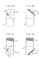
- the upper conveying path exit is made to correspond to the left end side of the drum 16, and the leading end of the reinforcing material piece 12A is affixed to the left end side of the drum 16 (see Fig. 4(A)).
- the reinforcing material piece 12A is successively fed-out, the drum 16 is rotated in the direction of arrow CW (in Fig. 1, the clockwise direction), and the left/right sliding member 34 moves toward the right end side of the drum 16 (see Fig. 4(B)).
- the cut reinforcing material piece 12A is distributed to the lower conveying path 72D by the distributing device 65.
- the position of the pair of rollers 66 of the distributing device 65 is moved by the cylinder 70 further downward than at the time of distributing the reinforcing material piece 12A to the upper conveying path 72U.
- the reinforcing material piece 12A which is distributed to the lower conveying path 72D is discharged from the lower conveying path exit toward the drum.
- the second conveying path exit is made to correspond to the left end side of the drum 16, and the leading end of the reinforcing material piece 12A is affixed to the left end side of the drum 16 (see Fig. 4(C)).
- the reinforcing material piece 12A is successively fed-out, the drum 16 is rotated in the direction of arrow CCW (in Fig. 1, the direction opposite to the clockwise direction), and the left/right sliding member 34 moves toward the right end side of the drum 16 (see Fig. 4(D)).
- a second reinforcing layer in which the cords rise to the right, is formed on the outer peripheral surface of the first reinforcing layer (reference numeral 76 of Fig. 5).
- the front/back sliding member 44 moves front and back (in the directions of approaching and moving away from the drum 16), and the upper conveying path exit and the lower conveying path exit can be disposed near to the drum 16.
- a case of forming two layers of belts is described, but thereafter, a third layer and layers thereafter can similarly be formed so as to form three or more intersecting belt layers.
- the reinforcing material 12 is nipped and conveyed by the nipping rollers 54, 56, 58, but the reinforcing material 12 may be conveyed by a roller conveyor or may be sucked and conveyed.
- the tire reinforcing layer forming device relating to the present invention is suited for use in tire manufacturing factories, and is suited to, for example, cases of forming reinforcing layers of a pneumatic tire.
Landscapes
- Engineering & Computer Science (AREA)
- Mechanical Engineering (AREA)
- Tyre Moulding (AREA)
Abstract
Description
Claims (3)
- A tire reinforcing layer forming device forming a tire reinforcing layer on an outer peripheral surface of a drum, the tire reinforcing layer forming device comprising:a drum able to rotate in both forward and reverse directions;conveying means for conveying, toward the drum, a strip-shaped reinforcing material in which a plurality of cords, which are aligned parallel to one another, are rubber coated;cutting means for cutting the reinforcing material obliquely with respect to a transverse direction;a first conveying path provided at a reinforcing material conveying direction downstream side of the cutting means, and guiding the reinforcing material toward one side in a peripheral direction of the drum;a second conveying path provided at the reinforcing material conveying direction downstream side of the cutting means, and guiding the reinforcing material toward another side in the peripheral direction of the drum;distributing means for distributing the reinforcing material, which has been cut, to one of the first conveying path and the second conveying path; andaxial direction moving means moving at least the first conveying path and the second conveying path along an axial direction of the drum.
- The tire reinforcing layer forming device of claim 1, wherein a reinforcing material exit of the first conveying path is inclined with respect to the axial direction of the drum, and
a reinforcing material exit of the second conveying path is inclined in a direction opposite the reinforcing material exit of the first conveying path. - The tire reinforcing layer forming device of claim 1 or claim 2, comprising:first moving means for moving at least the first conveying path and the second conveying path in a radial direction orthogonal to the axial direction of the drum, and in directions of approaching and moving away from the drum;first moving means for moving at least the first conveying path and the second conveying path in directions of approaching and moving away from the drum which are orthogonal to the axial direction of the drum; andsecond moving means for moving at least the first conveying path and the second conveying path in a direction orthogonal to both a moving direction by the first moving means and the axial direction of the drum.
Applications Claiming Priority (3)
| Application Number | Priority Date | Filing Date | Title |
|---|---|---|---|
| JP2003013282A JP4238040B2 (en) | 2003-01-22 | 2003-01-22 | Tire reinforcement layer forming device |
| JP2003013282 | 2003-01-22 | ||
| PCT/JP2004/000550 WO2004065110A1 (en) | 2003-01-22 | 2004-01-22 | Device of forming tire reinforcing layer |
Publications (3)
| Publication Number | Publication Date |
|---|---|
| EP1588832A1 true EP1588832A1 (en) | 2005-10-26 |
| EP1588832A4 EP1588832A4 (en) | 2006-05-24 |
| EP1588832B1 EP1588832B1 (en) | 2008-07-16 |
Family
ID=32767354
Family Applications (1)
| Application Number | Title | Priority Date | Filing Date |
|---|---|---|---|
| EP04704338A Expired - Lifetime EP1588832B1 (en) | 2003-01-22 | 2004-01-22 | Device of forming tire reinforcing layer |
Country Status (5)
| Country | Link |
|---|---|
| US (1) | US7487814B2 (en) |
| EP (1) | EP1588832B1 (en) |
| JP (1) | JP4238040B2 (en) |
| DE (1) | DE602004015070D1 (en) |
| WO (1) | WO2004065110A1 (en) |
Cited By (5)
| Publication number | Priority date | Publication date | Assignee | Title |
|---|---|---|---|---|
| WO2009004396A1 (en) * | 2007-06-29 | 2009-01-08 | Pirelli Tyre S.P.A. | Process and apparaptus for manufacturing tyres for vehicle wheels |
| WO2009033493A1 (en) | 2007-09-10 | 2009-03-19 | Pirelli Tyre S.P.A. | Process and apparatus for manufacturing a reinforcing structure for tyres of vehicles |
| EP2607064A1 (en) * | 2011-12-22 | 2013-06-26 | The Goodyear Tire & Rubber Company | Method and apparatus for applying a sheet of flexible material to a cylindrical body or for applying a ply onto a conveyor belt |
| US8800629B2 (en) | 2011-12-22 | 2014-08-12 | The Goodyear Tire & Rubber Company | Tire ply applier |
| US9114581B2 (en) | 2011-12-22 | 2015-08-25 | The Goodyear Tire & Rubber Company | Method of applying ply to a tire building drum |
Families Citing this family (12)
| Publication number | Priority date | Publication date | Assignee | Title |
|---|---|---|---|---|
| JP4346436B2 (en) * | 2003-12-25 | 2009-10-21 | 横浜ゴム株式会社 | Pneumatic tire and manufacturing method thereof |
| US7344614B2 (en) | 2004-11-01 | 2008-03-18 | The Goodyear Tire & Rubber Company | Tire breaker strip application method and tire fabricated therefrom |
| JP5134733B2 (en) * | 2008-12-11 | 2013-01-30 | ピレリ・タイヤ・ソチエタ・ペル・アツィオーニ | Manufacturing method and apparatus for vehicle wheel tire |
| US11691818B2 (en) | 2013-01-11 | 2023-07-04 | Multilift, Inc. | Method and system for conveying articles and an apparatus for doing the same |
| US9260247B2 (en) | 2013-01-11 | 2016-02-16 | Multilift, Inc. | Method and system for conveying articles and an apparatus for doing the same |
| US9061830B2 (en) | 2013-01-11 | 2015-06-23 | Multilift, Inc. | Method and system for conveying tires and an apparatus for doing the same |
| US11066243B2 (en) | 2013-01-11 | 2021-07-20 | Multilift, Inc. | Method and system for conveying articles and an apparatus for doing the same |
| MX379010B (en) | 2013-03-28 | 2025-03-10 | Pirelli | PROCESS AND APPARATUS FOR THE MANUFACTURE OF RIMS FOR VEHICLE WHEELS. |
| US9992917B2 (en) | 2014-03-10 | 2018-06-05 | Vulcan GMS | 3-D printing method for producing tungsten-based shielding parts |
| US10766710B2 (en) | 2018-02-16 | 2020-09-08 | Multilift, Inc. | Vehicle-mounted conveyor system |
| US11332321B2 (en) | 2018-06-04 | 2022-05-17 | Multilift, Inc. | Vehicle-mounted conveyor system |
| US10913381B2 (en) | 2018-06-04 | 2021-02-09 | Multilift, Inc. | Vehicle-mounted conveyor system |
Family Cites Families (13)
| Publication number | Priority date | Publication date | Assignee | Title |
|---|---|---|---|---|
| IT1189672B (en) * | 1986-05-20 | 1988-02-04 | Firestone Int Dev Spa | METHOD FOR THE HOT PRODUCTION OF TIRES |
| JP3494269B2 (en) * | 1996-10-29 | 2004-02-09 | 横浜ゴム株式会社 | Method and apparatus for attaching band-shaped material |
| JPH1199564A (en) | 1997-09-26 | 1999-04-13 | Yokohama Rubber Co Ltd:The | Pneumatic radial tire and method of manufacturing the same |
| JP3853067B2 (en) * | 1998-04-14 | 2006-12-06 | 横浜ゴム株式会社 | Band material pasting device |
| JP4358350B2 (en) | 1999-04-19 | 2009-11-04 | 株式会社ブリヂストン | Method and apparatus for forming tire reinforcing layer |
| JP4259698B2 (en) * | 1999-10-12 | 2009-04-30 | 横浜ゴム株式会社 | Method and apparatus for manufacturing belt member |
| JP2001232695A (en) * | 2000-02-22 | 2001-08-28 | Toyo Tire & Rubber Co Ltd | Method of molding unvulcanized tire belt |
| JP4697824B2 (en) * | 2000-11-14 | 2011-06-08 | 東洋ゴム工業株式会社 | Carcass ply manufacturing apparatus and manufacturing method |
| US6849146B2 (en) * | 2000-10-25 | 2005-02-01 | Toyo Tire & Rubber Co., Ltd. | Carcass ply producing apparatus, carcass ply producing method and pneumatic tire |
| US6797095B2 (en) | 2000-11-29 | 2004-09-28 | Pirelli Pneumatici S.P.A. | Method and plant for manufacturing a belt structure, a belt package and a crown structure of a green tire |
| US20030051794A1 (en) * | 2001-01-12 | 2003-03-20 | Nobuyuki Suda | Tire construction member producing method and device therefor |
| JP2003062916A (en) * | 2001-08-29 | 2003-03-05 | Sumitomo Rubber Ind Ltd | Method and apparatus for feeding belt-shaped rubber member |
| JP2003251711A (en) * | 2002-03-01 | 2003-09-09 | Toyo Tire & Rubber Co Ltd | Tire belt forming apparatus and belt forming method |
-
2003
- 2003-01-22 JP JP2003013282A patent/JP4238040B2/en not_active Expired - Fee Related
-
2004
- 2004-01-22 DE DE602004015070T patent/DE602004015070D1/en not_active Expired - Fee Related
- 2004-01-22 WO PCT/JP2004/000550 patent/WO2004065110A1/en not_active Ceased
- 2004-01-22 US US10/543,192 patent/US7487814B2/en not_active Expired - Fee Related
- 2004-01-22 EP EP04704338A patent/EP1588832B1/en not_active Expired - Lifetime
Cited By (6)
| Publication number | Priority date | Publication date | Assignee | Title |
|---|---|---|---|---|
| WO2009004396A1 (en) * | 2007-06-29 | 2009-01-08 | Pirelli Tyre S.P.A. | Process and apparaptus for manufacturing tyres for vehicle wheels |
| WO2009033493A1 (en) | 2007-09-10 | 2009-03-19 | Pirelli Tyre S.P.A. | Process and apparatus for manufacturing a reinforcing structure for tyres of vehicles |
| KR101331920B1 (en) * | 2007-09-10 | 2013-11-21 | 피렐리 타이어 소시에떼 퍼 아찌오니 | Process and apparatus for manufacturing a reinforcing structure for tyres of vehicles |
| EP2607064A1 (en) * | 2011-12-22 | 2013-06-26 | The Goodyear Tire & Rubber Company | Method and apparatus for applying a sheet of flexible material to a cylindrical body or for applying a ply onto a conveyor belt |
| US8800629B2 (en) | 2011-12-22 | 2014-08-12 | The Goodyear Tire & Rubber Company | Tire ply applier |
| US9114581B2 (en) | 2011-12-22 | 2015-08-25 | The Goodyear Tire & Rubber Company | Method of applying ply to a tire building drum |
Also Published As
| Publication number | Publication date |
|---|---|
| US7487814B2 (en) | 2009-02-10 |
| JP4238040B2 (en) | 2009-03-11 |
| WO2004065110A1 (en) | 2004-08-05 |
| DE602004015070D1 (en) | 2008-08-28 |
| EP1588832A4 (en) | 2006-05-24 |
| US20060130958A1 (en) | 2006-06-22 |
| JP2004261965A (en) | 2004-09-24 |
| EP1588832B1 (en) | 2008-07-16 |
Similar Documents
| Publication | Publication Date | Title |
|---|---|---|
| EP1588832B1 (en) | Device of forming tire reinforcing layer | |
| KR20150127700A (en) | Singulator conveyor | |
| JP2019509190A (en) | Compact 4-axis fiber placement device | |
| RU2742550C2 (en) | Apparatus and method of cutting a continuous line into tyre components | |
| CN104918778B (en) | Rubber tape sticking device | |
| EP2772349A1 (en) | Auto-adjustable wire precast system | |
| US11999015B2 (en) | System and method for cutting film | |
| JP7292575B2 (en) | Conveying roller and slitting device | |
| TWI687305B (en) | Cutting station for a tire building machine and method performed therein | |
| JP7056054B2 (en) | Rubber strip transfer device | |
| CN114555492A (en) | Branch device | |
| KR102621500B1 (en) | Device for banding products | |
| WO2019088218A1 (en) | Component aligning apparatus | |
| JP6226470B2 (en) | Absorbent article conveying apparatus and conveying method | |
| JP2004017499A (en) | Method for manufacturing strip-joint, and apparatus for manufacturing strip-joint used therefor | |
| KR20130002409A (en) | Device for preventing deviation of belt conveyor | |
| JP3396369B2 (en) | Method and apparatus for manufacturing tire molded member | |
| JP5695432B2 (en) | Belt ply forming method | |
| JP5092709B2 (en) | Roller conveyor equipment | |
| JP2012091913A (en) | Carrying device of bar | |
| JPH0623702A (en) | Carrier | |
| JP2025117798A (en) | Container Alignment Device | |
| JPH0343198A (en) | Cutting device for prepreg sheet | |
| JP6482376B2 (en) | Article guidance apparatus in conveying apparatus | |
| JP2006298523A (en) | Ball conveyor |
Legal Events
| Date | Code | Title | Description |
|---|---|---|---|
| PUAI | Public reference made under article 153(3) epc to a published international application that has entered the european phase |
Free format text: ORIGINAL CODE: 0009012 |
|
| 17P | Request for examination filed |
Effective date: 20050728 |
|
| AK | Designated contracting states |
Kind code of ref document: A1 Designated state(s): AT BE BG CH CY CZ DE DK EE ES FI FR GB GR HU IE IT LI LU MC NL PT RO SE SI SK TR |
|
| AX | Request for extension of the european patent |
Extension state: AL LT LV MK |
|
| DAX | Request for extension of the european patent (deleted) | ||
| RBV | Designated contracting states (corrected) |
Designated state(s): DE FR HU IT |
|
| A4 | Supplementary search report drawn up and despatched |
Effective date: 20060407 |
|
| 17Q | First examination report despatched |
Effective date: 20060911 |
|
| GRAP | Despatch of communication of intention to grant a patent |
Free format text: ORIGINAL CODE: EPIDOSNIGR1 |
|
| GRAS | Grant fee paid |
Free format text: ORIGINAL CODE: EPIDOSNIGR3 |
|
| GRAA | (expected) grant |
Free format text: ORIGINAL CODE: 0009210 |
|
| AK | Designated contracting states |
Kind code of ref document: B1 Designated state(s): DE FR HU IT |
|
| REF | Corresponds to: |
Ref document number: 602004015070 Country of ref document: DE Date of ref document: 20080828 Kind code of ref document: P |
|
| PLBE | No opposition filed within time limit |
Free format text: ORIGINAL CODE: 0009261 |
|
| STAA | Information on the status of an ep patent application or granted ep patent |
Free format text: STATUS: NO OPPOSITION FILED WITHIN TIME LIMIT |
|
| 26N | No opposition filed |
Effective date: 20090417 |
|
| REG | Reference to a national code |
Ref country code: HU Ref legal event code: AG4A Ref document number: E005306 Country of ref document: HU |
|
| PG25 | Lapsed in a contracting state [announced via postgrant information from national office to epo] |
Ref country code: DE Free format text: LAPSE BECAUSE OF NON-PAYMENT OF DUE FEES Effective date: 20090801 |
|
| REG | Reference to a national code |
Ref country code: FR Ref legal event code: ST Effective date: 20091030 |
|
| PG25 | Lapsed in a contracting state [announced via postgrant information from national office to epo] |
Ref country code: HU Free format text: LAPSE BECAUSE OF NON-PAYMENT OF DUE FEES Effective date: 20090123 |
|
| PG25 | Lapsed in a contracting state [announced via postgrant information from national office to epo] |
Ref country code: FR Free format text: LAPSE BECAUSE OF NON-PAYMENT OF DUE FEES Effective date: 20090202 |
|
| PG25 | Lapsed in a contracting state [announced via postgrant information from national office to epo] |
Ref country code: IT Free format text: LAPSE BECAUSE OF NON-PAYMENT OF DUE FEES Effective date: 20090122 |