EP1588123B1 - Method and apparatus for determining the clearance between a turbine shroud and a tip of a moving turbine blade - Google Patents
Method and apparatus for determining the clearance between a turbine shroud and a tip of a moving turbine blade Download PDFInfo
- Publication number
- EP1588123B1 EP1588123B1 EP04705818A EP04705818A EP1588123B1 EP 1588123 B1 EP1588123 B1 EP 1588123B1 EP 04705818 A EP04705818 A EP 04705818A EP 04705818 A EP04705818 A EP 04705818A EP 1588123 B1 EP1588123 B1 EP 1588123B1
- Authority
- EP
- European Patent Office
- Prior art keywords
- turbine
- delay
- collimator lens
- blade tip
- clearance
- Prior art date
- Legal status (The legal status is an assumption and is not a legal conclusion. Google has not performed a legal analysis and makes no representation as to the accuracy of the status listed.)
- Expired - Lifetime
Links
Images
Classifications
-
- G—PHYSICS
- G01—MEASURING; TESTING
- G01B—MEASURING LENGTH, THICKNESS OR SIMILAR LINEAR DIMENSIONS; MEASURING ANGLES; MEASURING AREAS; MEASURING IRREGULARITIES OF SURFACES OR CONTOURS
- G01B11/00—Measuring arrangements characterised by the use of optical techniques
- G01B11/14—Measuring arrangements characterised by the use of optical techniques for measuring distance or clearance between spaced objects or spaced apertures
Definitions
- the invention relates to a method for determining the clearance between a turbine shroud and a turbine to blade tip according to claim 1 and an apparatus for determining the clearance according to claim 11.
- Preferred embodiments are subject of the dependent claim 2-10, and 12-15.
- Leakage flows i.e. fluid flowing through the gap between the blade tips and the shroud of a turbine or compressor, are responsible for a significant percentage of overall losses in gas turbines and can also locally increase the heat transfer. Due to different expansion coefficients and heating rates, the tip clearance is not constant, but changes during the turbine start-up and shutdown. Also, wear and tear increases the tip clearance slowly over the time.
- the turbine has to be designed such that the blades do not touch the turbine shroud under normal operating conditions because it would lead to excessive wear or even damage.
- US-A-5,572,039 discloses an apparatus which enables the clearance between seal fins on rotating blades and adjacent fixed structure to be observed during rotation and comprises refracting prisms on the fixed structure arranged so as to straddle sealing fins on the blades.
- the stage of blades on their associated disc are moved toward the fixed structure and light, which is refracted through the prisms, is obscured by the fins.
- the ratio of obscured to unobscured light is utilized to generate electrical signals, which are then manipulated so as to indicated the magnitude of the clearance.
- US-A-5,739,524 concerns a dynamic sensor for sensing the distance and the position of a surface moving past said sensor.
- EP 0 762 078 discloses an optical method of measurement of the thickness and refractive index of a transparent film having a single layer or multiple layers of different refractive indices.
- the film to be measured is placed between two surfaces serving as reference surfaces.
- the film is measured by means of low-coherence light directed at the reference surfaces and through the film and determining the thickness and refractive index by means of interference signals resulting from the light reflected off the reference surfaces and the front and back surfaces of the transparent film.
- US 5,448,357 discloses an optical heterodyne system using a light source producing light beams of two different wavelengths and mutual coherence for the detection of the position of an object by means of interference signals resulting from light signals diffracted by a grating arranged on the object to be measured and light signals reflected off the surfaces of a Kersten prism.
- US 5,612,813 discloses an optical isolator including a Faraday rotator with an alignment of its TE-plane between the polarization planes of the polarization filters.
- US 5,422,477 discloses an optical system for sensing the rotation of a rotatable object and simultaneous sensing of the position of a displaceable object.
- the system includes an electro-optical unit that produces, among others, an intensity modulated (IM) and rf chirped optical signal that is directed by means of an optical fiber to a position sensor shown in figure 4.
- the position sensor comprises a collimator lens and a back reflecting corner cub attached to the object.
- the position of the object is determined by means of a transducing unit and the time the IM optical signal is delayed by its travel to and from the object.
- a method of determining the clearance between a turbine shroud and a turbine moving blade tip as written in the features of claim 1 was found.
- the invention is as well directed to an apparatus of determining the clearance between a turbine shroud and a turbine moving blade tip as written in the features of claim 11.
- a variable attenuator can be arranged in the reference arm.
- a fiber optical isolator between the light source and the collimator lens can be arranged. It can further comprise the step of filtering the beam after the step of combining the beams from the reference arm and the delay arm in a beam combiner and before the step of detecting the intensity of the power spectrum at the chosen frequency by means of an optical filter.
- the emitting and detecting of the low-coherence light to and from the collimator lens and blade tip can be done by means of a circulator or through two separate fibers for the light going to and coming from the object.
- the sum of the two fiber lengths-then has to be compensated by a fixed delay in the-delay arm.
- the clearance between a shroud and a moving turbine blade tip can be determined.
- the collimator lens is then arranged at the shroud, e.g. in a cooled recess.
- the clearance can then be determined during the operation of the turbine, e.g. during the start-up or shutdown of the turbine. It is also possible to determine the clearance of a plurality of turbine blades during their passage at a single collimator lens arranged at the shroud. Simultaneously to the tip clearance, the blade passage times are measured allowing the detection of blade oscillations (tip timing).
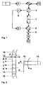
- Fig. 1 shows the schematic setup of a low-coherence interferometer according to the present invention for measuring the tip clearance D between a tip 15 of a turbine blade 14 and the shroud 16 of turbine.
- a superluminescent diode such as an example a Superlum Diode, model SLD56-HP2, 10 mW ex single mode fiber at 1310 nm, 35 nm spectral width, 10 -3 maximum allowable backscattering, emits low-coherence light into a single-mode fiber.
- a fiber-optical isolator 2 ( ⁇ -60 dB backscattering) protects the sensitive light source from back-reflections.
- the light passes through an optical circulator 3 and a collimator lens 13 to the turbine blade 14 (not shown in Fig. 1).
- the collimator lens 13 is arranged flush with the shroud 16, e.g. in a cooled recess.
- the clearance D can then be determined during the operation of the turbine, e.g. during the start-up or shutdown of the turbine. It is also possible to determine the distance D of a plurality of turbine blades 14. during their passage at a single collimator lens 13 arranged at the shroud 16. ⁇ means the rotation speed of turbine blade 14.
- a small fraction of the light 12 is reflected from the passing blade tip 15 back onto the collimator lens 13 and into the fiber towards the circulator 3, where it is directed into the interferometer.
- the light from the turbine is split into two interferometer arms by a beam splitter 4.
- an acousto-optical modulator 5 shifts the frequency by 55 MHz and a variable attenuator 6 allows adjusting the intensity ratio between the reference and the delay arm.
- the delay arm contains motorized variable delay line 7 (General Photonics, 0 - 330 ps delay, 0.3 ⁇ m steps, 10 mm/s travel).
- the two arms are combined with a beam combiner 8.
- a photoreceiver (New Focus, model 1811, 900 - 1700 nm, 125 MHz bandwidth) is used as detector 10. Provisions are made for an optical filter 9, which can be used in front of the detector 10 to filter out noise due to flow luminosity in the turbine.
- the data is recorded and preprocessed on a digital storage oscilloscope and transferred to a Personal Computer 11.
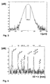
- Fig. 3 shows the coherence function of the light source 1.
- the -3 dB width is only 140 ⁇ m and two light rays can thus only interfere with each other when the path length difference is less than this coherence length.
- the path length between turbine and the interferometer of the ray A is longer than that of rays B and C.
- the distance between the tip blade 15 and the collimator lens' 13 back surfaces, i.e. the tip clearance is D and the thickness of the collimator lens 13 is d.
- the path length differences between ray A and B or C are 2(D+d) and 2D, respectively.
- the frequency of the acousto-optical modulator 5 55 MHz is seen at the detector 10 together with the signal components from the other, non-interfering contributions of other rays and flow luminosity.
- a rotating (60Hz) aluminum disc with notches of various depths (0-4.8 mm) is used to simulate a turbine stage.
- the standard collimator lens 13 used is optimized for the wavelength of the superluminescent diode and the surface reflections from the lens are insufficient. This will not be the case with the custom made sapphire optics for use in the hot turbine.
- the measurement time is artificially limited to 1 ⁇ s to reproduce typical blade passage times.
- the power spectrum intensity at 55 MHz of the detector 11 output is recorded while the delay line sweeps through its range of 100 mm, which is the upper bound of the measurement range, in steps of 30 ⁇ m.
- the sweep rate has to be set such that the delay changes by less than the coherence length per revolution of the disc.
- the current timing setup only one slit is measured, but the measurement of all the slits (blades 14) simultaneously can be achieved by binning the signals for each blade 14 and is thus merely a matter of modifying the data processing.
- the horizontal scale is already converted into depth k, i.e., the factor of 2 in the path length distance is accounted for and the speed of the light is used in the conversion.
- Several peaks are visible, indicating various different interfering ray combinations.
- the second peak at 1.83 mm ⁇ d' represents interference between ray B (front surface of lens) going through the delayed interferometer arm and ray C (back surface of lens) going through the reference arm.
- the symbol d' denotes the thickness of the simulated lens multiplied with its index of refraction.
- the peak labeled "I ref /C delay " originates from the interference between ray A (blade tip 15) going through the reference arm and ray C (back surface of lens) going through the delay arm.
- the spacing between this peak and the first peak is the measured tip clearance D.
- the following peak at 6.64 mm ⁇ D + d' comes from the interference between again ray A and ray B (front surface of lens).
- the spacing of the latter two peaks is d' ⁇ 1.84 mm again.
- the same path length difference results from the combination A* ref /C delay .
- Three additional weaker peaks are labeled in Fig. 4, which are due to multiple reflection within the lens.
- the peak at 3.67 mm ⁇ 2d' comes from the interference between ray C going through the delay arm and a ray C, which has been reflected back and forth once between the two lens surfaces.
- the table 1 summarizes these results. Not all peaks listed were observed in every measurement and not all permutations between d' and D for each peak are given. Tab. 1 Peak location Beam paths In Fig.
- the signals from multiple reflections within the setup or in the turbine are 15dB weaker than the main peaks.
- the optically measured value for the notch depth of 4.79 is very close to the nominal value of 4.80 mm.
- the statistical error is estimated to be half of the coherence length.
- Systematic errors are due to errors in the assumed index of refraction of the lens, to slight variations in the speed of light due to changing densities and temperatures in the flow though the tip clearance D, and to positioning errors of the variable delay line. The sum of these effects is estimated to be less than 100 ⁇ m.
- the tip clearance D is encoded multiple times into each scan (see Fig. 4), which can be used to reduce the uncertainty. Problems can arise when d and D are integer multiples of each other. Multiple peaks would then coincide, making the measurements for d and D indistinguishable.
- the accuracy is independent if the distance between probe and object. Note, however, that the amount of light reflected back into the fiber decreases with square of the distance and that hence the signal-to-noise-ratio will decrease with increasing distance.
- the noise rejection is excellent, and the signal-to-noise ratio is > 30 dB.
- the modulation depth of the raw signal in case of interference is on the order of 10%. These values will deteriorate in the presence of flow luminosity, but the use of an optical bandpass filter, which was not integrated so far, can suppress much of the undesired light and avoid saturation of the detector.
- a trade-off exists between the accuracy and the speed of the technique. The accuracy is determined to a large degree by the coherence length of the light source. The lower the coherence length, the higher the accuracy, but also the lower the maximum sweeping speed of the delay line.
- a setup without circulator 3 is possible, but this would require two separate fibers of for the light going to and coming from the turbine. The sum of the two fiber lengths then has to be compensated by a fixed delay in the delay arm.
- the frequency shift of the acousto-optical modulator 5 was chosen large enough such that a sufficient large number of oscillations would fall within the blade passage time of 1 ⁇ s, but low enough such that a special high bandwidth photodetector is not required.
- An encoder on the turbine shaft provides a reference time. With the known position and number of blades 14 in the stages, time windows (a few times the actual passage time) for their passage at the probe location can be defined. Data is required during these windows and the power spectrum intensity at 55 MHz is recorded with the current blade number. The delay line is moved after each shaft revolution until the desired measurement range is covered. This yields scans as shown in Fig. 4 for each blade 14, which can be analyzed.
- the measurement of the tip clearance D with the presented method according to the present invention has a high accuracy (error less than 100 ⁇ m), which is independent of the distance between the collimator lens 3 and the blade tip 15.
- the technique can yield data once every second for each blade 14. This allows the monitoring of transient effects during the turbine start-up and shutdown. Variations in the fluid or material effects have no influence other than by minimal changes of the speed of light.
- the blade passage times are measured allowing one to detect blade oscillations (tip timing).
- the technique Due to the binary character (55 MHz signal present/not present), the technique is expected to be very robust being exposed to the harsh environments inside a hot turbine. Only a single fiber of arbitrary length has to enter the turbine housing. The remaining optics and electronics can be located at an arbitrary distance from the turbine, thus separating it from heat, noise, and vibrations.
Landscapes
- Physics & Mathematics (AREA)
- General Physics & Mathematics (AREA)
- Length Measuring Devices By Optical Means (AREA)
- Instruments For Measurement Of Length By Optical Means (AREA)
- Measurement Of Velocity Or Position Using Acoustic Or Ultrasonic Waves (AREA)
Abstract
Description
- The invention relates to a method for determining the clearance between a turbine shroud and a turbine to blade tip according to
claim 1 and an apparatus for determining the clearance according toclaim 11. - Preferred embodiments are subject of the dependent claim 2-10, and 12-15.
- Leakage flows, i.e. fluid flowing through the gap between the blade tips and the shroud of a turbine or compressor, are responsible for a significant percentage of overall losses in gas turbines and can also locally increase the heat transfer. Due to different expansion coefficients and heating rates, the tip clearance is not constant, but changes during the turbine start-up and shutdown. Also, wear and tear increases the tip clearance slowly over the time. The turbine has to be designed such that the blades do not touch the turbine shroud under normal operating conditions because it would lead to excessive wear or even damage.
- Given real time tip clearance data, future turbines might be able to actively control the tip clearance by adjusting the amount of cooling air to the blades or shroud. Monitoring the tip clearance can also provide valuable information about the condition of the stage for maintenance. Current tip-clearance probes are of inductive or capacitive type such as described in US-B1-6,437,583, US-A-6,114,862, US-B1-6,320,394 or US-B1-6,362,633 having an accuracy of typically 5%. This is sufficient where the probe can be mounted flush with the turbine casing, and the absolute errors can be kept small. The maximum operating temperature of the sensors is near the Curie point of the rare earth magnets used, which is well below the temperature in the first turbine stages. The high temperatures also make it impossible to provide optical access for the optical probes flush with the shroud. When mounting the probes in a protective recess within the shroud, then the relative measurement errors become to large in absolute terms.
- US-A-5,572,039 discloses an apparatus which enables the clearance between seal fins on rotating blades and adjacent fixed structure to be observed during rotation and comprises refracting prisms on the fixed structure arranged so as to straddle sealing fins on the blades. The stage of blades on their associated disc are moved toward the fixed structure and light, which is refracted through the prisms, is obscured by the fins. In one embodiment, the ratio of obscured to unobscured light is utilized to generate electrical signals, which are then manipulated so as to indicated the magnitude of the clearance.
- US-A-5,739,524 concerns a dynamic sensor for sensing the distance and the position of a surface moving past said sensor.
- EP 0 762 078 discloses an optical method of measurement of the thickness and refractive index of a transparent film having a single layer or multiple layers of different refractive indices. The film to be measured is placed between two surfaces serving as reference surfaces. The film is measured by means of low-coherence light directed at the reference surfaces and through the film and determining the thickness and refractive index by means of interference signals resulting from the light reflected off the reference surfaces and the front and back surfaces of the transparent film.
- US 5,448,357 discloses an optical heterodyne system using a light source producing light beams of two different wavelengths and mutual coherence for the detection of the position of an object by means of interference signals resulting from light signals diffracted by a grating arranged on the object to be measured and light signals reflected off the surfaces of a Kersten prism.
- US 5,612,813 discloses an optical isolator including a Faraday rotator with an alignment of its TE-plane between the polarization planes of the polarization filters.
- US 5,422,477 discloses an optical system for sensing the rotation of a rotatable object and simultaneous sensing of the position of a displaceable object. The system includes an electro-optical unit that produces, among others, an intensity modulated (IM) and rf chirped optical signal that is directed by means of an optical fiber to a position sensor shown in figure 4. The position sensor comprises a collimator lens and a back reflecting corner cub attached to the object. The position of the object is determined by means of a transducing unit and the time the IM optical signal is delayed by its travel to and from the object.
- It is the aim of the present invention to find a new probe configuration and an method of measuring the clearance between a moving turbine blade tip and a turbine shroud, where the measurement error is independent of the distance between a probe and blade tip such that the sensor can be used in the first turbine stages by mounting it in a cooled recess.
- According to the invention a method of determining the clearance between a turbine shroud and a turbine moving blade tip as written in the features of
claim 1 was found. The invention is as well directed to an apparatus of determining the clearance between a turbine shroud and a turbine moving blade tip as written in the features ofclaim 11. - For adjusting the intensity of the ratio of the beams between the reference arm and the delay arm, a variable attenuator can be arranged in the reference arm. To protect the sensitive light source from back-reflections, a fiber optical isolator between the light source and the collimator lens can be arranged. It can further comprise the step of filtering the beam after the step of combining the beams from the reference arm and the delay arm in a beam combiner and before the step of detecting the intensity of the power spectrum at the chosen frequency by means of an optical filter.
- The emitting and detecting of the low-coherence light to and from the collimator lens and blade tip can be done by means of a circulator or through two separate fibers for the light going to and coming from the object. The sum of the two fiber lengths-then has to be compensated by a fixed delay in the-delay arm.
- With the inventive method, the clearance between a shroud and a moving turbine blade tip can be determined. The collimator lens is then arranged at the shroud, e.g. in a cooled recess. The clearance can then be determined during the operation of the turbine, e.g. during the start-up or shutdown of the turbine. It is also possible to determine the clearance of a plurality of turbine blades during their passage at a single collimator lens arranged at the shroud. Simultaneously to the tip clearance, the blade passage times are measured allowing the detection of blade oscillations (tip timing).
- This invention is illustrated in the accompanying drawing, in which
- Fig. 1
- shows an experimental setup of the low-coherence interferometer,
- Fig. 2
- shows the reflections from the collimator lens surfaces and blade tip,
- Fig.3
- illustrates the coherence function of the superluminescent diode (Power spectrum intensity at 55 MHz [dB] vs. Delay t [µm]) and
- Fig. 4
- shows the power spectrum intensity at 55 MHz [dB] vs. the delay for a test object rotating at 60 Hz for a simulated tip clearance of 4.8 mm.
- The drawings show only parts important for the invention.
- Fig. 1 shows the schematic setup of a low-coherence interferometer according to the present invention for measuring the tip clearance D between a
tip 15 of aturbine blade 14 and theshroud 16 of turbine. Aslight source 1, a superluminescent diode, such as an example a Superlum Diode, model SLD56-HP2, 10 mW ex single mode fiber at 1310 nm, 35 nm spectral width, 10-3 maximum allowable backscattering, emits low-coherence light into a single-mode fiber. A fiber-optical isolator 2 (< -60 dB backscattering) protects the sensitive light source from back-reflections. The light passes through anoptical circulator 3 and acollimator lens 13 to the turbine blade 14 (not shown in Fig. 1). - As seen in Fig. 2, the
collimator lens 13 is arranged flush with theshroud 16, e.g. in a cooled recess. The clearance D can then be determined during the operation of the turbine, e.g. during the start-up or shutdown of the turbine. It is also possible to determine the distance D of a plurality ofturbine blades 14. during their passage at asingle collimator lens 13 arranged at theshroud 16. ω means the rotation speed ofturbine blade 14. As seen as well in Fig. 2, a small fraction of thelight 12 is reflected from thepassing blade tip 15 back onto thecollimator lens 13 and into the fiber towards thecirculator 3, where it is directed into the interferometer. Similarly, small amounts of theoriginal light 12 are reflected from both surfaces of thecollimator lens 13 by Fresnel reflection (rays B and C). It is denoted the light reflected from theblade tips 15 as ray A, and the light reflected from the lens' front and back surfaces as rays B and C, respectively. Multiple internal reflections are possible and are denoted by additional asterisks. - The light from the turbine is split into two interferometer arms by a
beam splitter 4. In the reference arm, an acousto-optical modulator 5 shifts the frequency by 55 MHz and avariable attenuator 6 allows adjusting the intensity ratio between the reference and the delay arm. The delay arm contains motorized variable delay line 7 (General Photonics, 0 - 330 ps delay, 0.3 µm steps, 10 mm/s travel). The two arms are combined with abeam combiner 8. A photoreceiver (New Focus, model 1811, 900 - 1700 nm, 125 MHz bandwidth) is used asdetector 10. Provisions are made for anoptical filter 9, which can be used in front of thedetector 10 to filter out noise due to flow luminosity in the turbine. The data is recorded and preprocessed on a digital storage oscilloscope and transferred to aPersonal Computer 11. - Fig. 3 shows the coherence function of the
light source 1. The -3 dB width is only 140 µm and two light rays can thus only interfere with each other when the path length difference is less than this coherence length. Denote the path length of the two interferometer arms (between thebeam splitter 4 and beam combiner 8) by Iref and Idelay. The path length between turbine and the interferometer of the ray A is longer than that of rays B and C. As seen in Fig. 2, the distance between thetip blade 15 and the collimator lens' 13 back surfaces, i.e. the tip clearance, is D and the thickness of thecollimator lens 13 is d. Then the path length differences between ray A and B or C are 2(D+d) and 2D, respectively. - If the
variable delay line 7 is set such that Iref + 2(D+d) = Idelay, e.g. then the part of ray A going through the reference arm can interfere with those parts of ray B which go through thedelay line 7. The frequency of the acousto-optical modulator 5 (55 MHz) is seen at thedetector 10 together with the signal components from the other, non-interfering contributions of other rays and flow luminosity. Similarly, interference between rays A and C is observed when Iref + 2D=Idelay. The system is capable of self-calibrating by checking for the delay, where rays B and C interfere with each other, i.e. when Iref + 2d = Idelay, because the thickness d and index of refraction of thecollimator lens 13 is known. - A rotating (60Hz) aluminum disc with notches of various depths (0-4.8 mm) is used to simulate a turbine stage. The
standard collimator lens 13 used is optimized for the wavelength of the superluminescent diode and the surface reflections from the lens are insufficient. This will not be the case with the custom made sapphire optics for use in the hot turbine. A clear plastic disc (CD-Rom stripped of its reflective layer, d=1.2 mm thickness) is glued onto the disc to simulate the two lens surfaces. The measurement time is artificially limited to 1 µs to reproduce typical blade passage times. The power spectrum intensity at 55 MHz of thedetector 11 output is recorded while the delay line sweeps through its range of 100 mm, which is the upper bound of the measurement range, in steps of 30 µm. The sweep rate has to be set such that the delay changes by less than the coherence length per revolution of the disc. In the current timing setup, only one slit is measured, but the measurement of all the slits (blades 14) simultaneously can be achieved by binning the signals for eachblade 14 and is thus merely a matter of modifying the data processing. - Fig. 4 shows the power spectrum intensity at 55 MHz versus the delay line setting for the rotating wheel form D = 4.8 mm. The horizontal scale is already converted into depth k, i.e., the factor of 2 in the path length distance is accounted for and the speed of the light is used in the conversion. Several peaks are visible, indicating various different interfering ray combinations. The first peak at the origin corresponds to interference between all rays and themselves, i.e. when both interferometer arms are of equal length (Iref = Idelay). Consequently, this is the strongest peak. The second peak at 1.83 mm ≈ d' represents interference between ray B (front surface of lens) going through the delayed interferometer arm and ray C (back surface of lens) going through the reference arm. The symbol d' denotes the thickness of the simulated lens multiplied with its index of refraction.
- The peak labeled "Iref/Cdelay" originates from the interference between ray A (blade tip 15) going through the reference arm and ray C (back surface of lens) going through the delay arm. The spacing between this peak and the first peak is the measured tip clearance D. The following peak at 6.64 mm ≈ D + d' comes from the interference between again ray A and ray B (front surface of lens). The spacing of the latter two peaks is d' ≈ 1.84 mm again. The same path length difference results from the combination A*ref/Cdelay. Three additional weaker peaks are labeled in Fig. 4, which are due to multiple reflection within the lens. The peak at 3.67 mm ≈ 2d', for example, comes from the interference between ray C going through the delay arm and a ray C, which has been reflected back and forth once between the two lens surfaces. The peak at 8.47 mm = D + 2d', is explained by delayed ray B and a ray A, which is reflected back forth once within the lens on its way back. The table 1 summarizes these results. Not all peaks listed were observed in every measurement and not all permutations between d' and D for each peak are given.
Tab. 1 Peak location Beam paths In Fig. 4 [mm] general Reference arm Delay arm 0 0 A, B, C A, B, C 1.83 D C B 2.98 D-d' A C 3.67 2d' C* B 4.79 D A C 6.64 D + d' A B 6.64 D+d' A* C -- 4d' C*** B - The signals from multiple reflections within the setup or in the turbine are 15dB weaker than the main peaks. The optically measured value for the notch depth of 4.79 is very close to the nominal value of 4.80 mm. The measured thickness of the lens has to be adjusted by its index of refraction (here: 1.55 according to standard ECMA-130 for CD-ROMs). The measured thickness is thus d = d'/1.55 = 1.19 mm, which is also very close to the conventionally measured value of 1.20 mm.
- The statistical error is estimated to be half of the coherence length. Systematic errors are due to errors in the assumed index of refraction of the lens, to slight variations in the speed of light due to changing densities and temperatures in the flow though the tip clearance D, and to positioning errors of the variable delay line. The sum of these effects is estimated to be less than 100 µm. The tip clearance D is encoded multiple times into each scan (see Fig. 4), which can be used to reduce the uncertainty. Problems can arise when d and D are integer multiples of each other. Multiple peaks would then coincide, making the measurements for d and D indistinguishable. The accuracy is independent if the distance between probe and object. Note, however, that the amount of light reflected back into the fiber decreases with square of the distance and that hence the signal-to-noise-ratio will decrease with increasing distance.
- The noise rejection is excellent, and the signal-to-noise ratio is > 30 dB. The modulation depth of the raw signal in case of interference is on the order of 10%. These values will deteriorate in the presence of flow luminosity, but the use of an optical bandpass filter, which was not integrated so far, can suppress much of the undesired light and avoid saturation of the detector. A trade-off exists between the accuracy and the speed of the technique. The accuracy is determined to a large degree by the coherence length of the light source. The lower the coherence length, the higher the accuracy, but also the lower the maximum sweeping speed of the delay line.
- A setup without
circulator 3 is possible, but this would require two separate fibers of for the light going to and coming from the turbine. The sum of the two fiber lengths then has to be compensated by a fixed delay in the delay arm. - The frequency shift of the acousto-
optical modulator 5 was chosen large enough such that a sufficient large number of oscillations would fall within the blade passage time of 1 µs, but low enough such that a special high bandwidth photodetector is not required. To measure allblades 14 simultaneously, one proceeds as follows: An encoder on the turbine shaft provides a reference time. With the known position and number ofblades 14 in the stages, time windows (a few times the actual passage time) for their passage at the probe location can be defined. Data is required during these windows and the power spectrum intensity at 55 MHz is recorded with the current blade number. The delay line is moved after each shaft revolution until the desired measurement range is covered. This yields scans as shown in Fig. 4 for eachblade 14, which can be analyzed. - The measurement of the tip clearance D with the presented method according to the present invention has a high accuracy (error less than 100 µm), which is independent of the distance between the
collimator lens 3 and theblade tip 15. A large measurement range up 50 mm, i.e. the half of the range of the optical delay line, is possible. For typical scenarios where the tip clearance D is within a range of a few millimeters, the technique can yield data once every second for eachblade 14. This allows the monitoring of transient effects during the turbine start-up and shutdown. Variations in the fluid or material effects have no influence other than by minimal changes of the speed of light. Simltaneously to the tip clearance D, the blade passage times are measured allowing one to detect blade oscillations (tip timing). - Due to the binary character (55 MHz signal present/not present), the technique is expected to be very robust being exposed to the harsh environments inside a hot turbine. Only a single fiber of arbitrary length has to enter the turbine housing. The remaining optics and electronics can be located at an arbitrary distance from the turbine, thus separating it from heat, noise, and vibrations.
- While the invention has been described by an example, it is apparent that other forms could be adopted by one skilled in the art. Accordingly, the scope of our invention is to be limited only by the attached claims.
-
- 1
- Light source
- 2
- Optical isolator
- 3
- Circulator
- 4
- Beam splitter
- 5
- Acousto-optical modulator
- 6
- Variable attenuator
- 7
- Variable delay line
- 8
- Beam combiner
- 9
- Optical filter
- 10
- Detector
- 11
- Computer
- 12
- Light
- 13
- Collimator lens
- 14
- Turbine blade
- 15
- Blade tip of
turbine blade 14 - 16
- Shroud
- A, B, C, A*, C*
- light rays
- d
- Thickness of the
collimator lens 13 - d'
- Optical thickness of
collimator lens 13 - D
- Tip clearance
- k
- Depth
- t
- Delay
- ω
- Rotation speed of
turbine blade 14
Claims (15)
- A method of determining the clearance (D) between a turbine shroud (16) and a tip (15) of a moving turbine blade (14) comprising the steps of(a) emitting a low-coherence light (12) from a light source (1),(b) directing the low-coherence light through a collimator lens (13) to the blade tip (15), wherein the collimator lens (13) is arranged at the turbine shroud (16),(c) directing light reflected from the collimator lens (13) and from the blade tip (15) to a beam splitter (4), which splits the light beam reflected from the collimator lens (13) and from the blade tip (15) into a reference beam within a reference arm and a delay beam within a delay arm,(d) shifting the frequency of the reference beam by means of an acousto-optical modulator (5) to a predetermined frequency,(e) scanning the time delay (At) of the delay beam by means of a variable delay line (7),(f) combining the reference beam and the delay beam by means of a beam combiner (8),(g) detecting the power spectrum due to the interference of the light reflected from the collimator lens (13) and from the moving blade tip (15) at the frequency determined by the acousto-optical modulator,(h) calculating from the obtained power spectrum the clearance (D) between the turbine shroud (16) and the moving turbine blade tip (15).
- The method according to claim 1, comprising the step of adjusting the ratio of the intensity of the reference beam to the intensity of the delay beam by means of a variable attenuator (6) placed in the reference beam.
- The method according to claim 1 or 2, comprising the step of directing the low-coherence light through a fiber optical isolator (2) prior to directing it to the collimator lens (13).
- The method according to any of the claims 1 through 3, comprising the step of filtering the beam emerging from the beam combiner (8) prior to detecting the power spectrum.
- The method according to any of the claims 1 through 4, wherein the low-coherence light (12) to and from the collimator lens (13) and the turbine blade tip (15) is directed by means of a circulator (3).
- The method according to any of the claims 1 through 4, wherein the low-coherence light (12) is directed to the turbine blade tip (15) and from the turbine blade tip (15) by means of two separate fibers.
- The method according to one of the claims 1 through 6, wherein the clearance (D) between the turbine shroud (16) and the turbine blade tip (15) is determined during the operation of the turbine.
- The method according to claim 7, wherein the clearance (D) between the turbine shroud (16) and the turbine blade tip (15) is determined during start-up or shutdown of the turbine.
- The method according to claim 8, wherein the clearance (D) between the turbine shroud (16) and a plurality of turbine blade tips (15) is determined.
- The method according to claim 9, wherein the point in time of each turbine blade (14) passage is determined.
- An apparatus for determining the clearance (D) between a turbine shroud (16) and a tip (15) of a moving turbine blade (14) comprising(a) a low-coherence light source (1),(b) a collimator lens (13) arranged at the turbine shroud (16),(c) a beam splitter (4) for splitting the light beam reflected from the collimator lens (13) and from the blade tip (15) into a reference beam within a reference arm and a delay beam within a delay arm,(d) an acousto-optical modulator (5) placed within the reference arm in the reference beam emerging from the beam splitter (4) for shifting the frequency of the reference beam to a predetermined frequency,(e) a variable delay line (7) placed within the delay arm in the delay beam emerging from the beam splitter (4) for scanning the time delay of the delay beam,(f) a beam combiner (8) for combining the reference beam and delay beam,(g) a detector (10) for detecting the light beam emerging from the beam combiner (8), and for detecting the power spectrum due to the interference of the light reflected from the collimate lens and from the moving blade tip at the frequency determinated by the accousto-optical modulator,(h) a processing unit connected to the detector (10) for calculating the clearance (D) between the turbine shroud (16) and the moving turbing blade tip (15).
- The apparatus according to claim 11, further comprising a circulator (3) between the low-coherence light source (1) and the collimator lens (13).
- The apparatus according to claim 11 or 12, further comprising a variable attenuator (6) in the reference beam.
- The apparatus according to one of the claims 11 through 13, further comprising a fiber optical isolator (2) between the low-coherence light source (1) and the collimator lens (13).
- The apparatus according to one of the claims 11 through 14, further comprising an optical filter (9) between the beam combiner (8) and the detector (10).
Priority Applications (1)
| Application Number | Priority Date | Filing Date | Title |
|---|---|---|---|
| EP04705818A EP1588123B1 (en) | 2003-01-30 | 2004-01-28 | Method and apparatus for determining the clearance between a turbine shroud and a tip of a moving turbine blade |
Applications Claiming Priority (4)
| Application Number | Priority Date | Filing Date | Title |
|---|---|---|---|
| EP03405044 | 2003-01-30 | ||
| EP03405044A EP1445577A1 (en) | 2003-01-30 | 2003-01-30 | A method and an apparatus for determining the distance between a collimator lens and an object |
| PCT/EP2004/050045 WO2004068064A2 (en) | 2003-01-30 | 2004-01-28 | A method and an apparatus for determining the distance between a collimator lens and an object |
| EP04705818A EP1588123B1 (en) | 2003-01-30 | 2004-01-28 | Method and apparatus for determining the clearance between a turbine shroud and a tip of a moving turbine blade |
Publications (2)
| Publication Number | Publication Date |
|---|---|
| EP1588123A2 EP1588123A2 (en) | 2005-10-26 |
| EP1588123B1 true EP1588123B1 (en) | 2007-06-06 |
Family
ID=32605479
Family Applications (2)
| Application Number | Title | Priority Date | Filing Date |
|---|---|---|---|
| EP03405044A Withdrawn EP1445577A1 (en) | 2003-01-30 | 2003-01-30 | A method and an apparatus for determining the distance between a collimator lens and an object |
| EP04705818A Expired - Lifetime EP1588123B1 (en) | 2003-01-30 | 2004-01-28 | Method and apparatus for determining the clearance between a turbine shroud and a tip of a moving turbine blade |
Family Applications Before (1)
| Application Number | Title | Priority Date | Filing Date |
|---|---|---|---|
| EP03405044A Withdrawn EP1445577A1 (en) | 2003-01-30 | 2003-01-30 | A method and an apparatus for determining the distance between a collimator lens and an object |
Country Status (6)
| Country | Link |
|---|---|
| US (1) | US7400418B2 (en) |
| EP (2) | EP1445577A1 (en) |
| JP (1) | JP2006515679A (en) |
| AT (1) | ATE364166T1 (en) |
| DE (1) | DE602004006833T2 (en) |
| WO (1) | WO2004068064A2 (en) |
Cited By (1)
| Publication number | Priority date | Publication date | Assignee | Title |
|---|---|---|---|---|
| EP2568583A1 (en) * | 2011-09-12 | 2013-03-13 | Alstom Hydro France | Temperature monitoring device for electric motor |
Families Citing this family (12)
| Publication number | Priority date | Publication date | Assignee | Title |
|---|---|---|---|---|
| GB2427683B (en) * | 2005-06-25 | 2007-06-20 | Rolls Royce Plc | A gap monitor arrangement |
| US7891938B2 (en) * | 2007-03-20 | 2011-02-22 | General Electric Company | Multi sensor clearance probe |
| GB0814877D0 (en) | 2008-08-15 | 2008-09-17 | Rolls Royce Plc | Clearance and wear determination apparatus |
| US20100079136A1 (en) | 2008-09-29 | 2010-04-01 | Rosemount Aerospace Inc. | Blade tip clearance measurement sensor and method for gas turbine engines |
| US20120169326A1 (en) * | 2010-12-30 | 2012-07-05 | General Electric Company | Methods, systems and apparatus for detecting material defects in combustors of combustion turbine engines |
| US9316479B2 (en) | 2012-09-20 | 2016-04-19 | United Technologies Corporation | Capacitance based clearance probe and housing |
| US9593941B2 (en) | 2014-09-24 | 2017-03-14 | Hood Technology Corporation | Clearance detection system and method using frequency identification |
| US10808570B2 (en) * | 2017-09-12 | 2020-10-20 | Raytheon Technologies Corporation | Low profile embedded blade tip clearance sensor |
| CN113123928B (en) * | 2019-12-31 | 2022-10-14 | 新疆金风科技股份有限公司 | Wind generating set and tower clearance monitoring method and device thereof |
| US12060865B2 (en) | 2020-09-24 | 2024-08-13 | Parker-Hannifin Corporation | Optical systems and methods for measuring turbine blade tip clearance |
| CN117870846A (en) * | 2023-02-22 | 2024-04-12 | 张引 | A blade tip timing system and a blade arrival detection device and a detection method thereof |
| US12535312B2 (en) * | 2024-05-31 | 2026-01-27 | Rtx Corporation | White light interferometer for measuring radial growth in components experiencing rotating stresses |
Family Cites Families (16)
| Publication number | Priority date | Publication date | Assignee | Title |
|---|---|---|---|---|
| GB2066449B (en) * | 1979-12-21 | 1984-03-21 | Rolls Royce | Monitoring distance variations |
| US4326804A (en) * | 1980-02-11 | 1982-04-27 | General Electric Company | Apparatus and method for optical clearance determination |
| GB8307534D0 (en) * | 1983-03-18 | 1983-04-27 | Rolls Royce | Optical determination of clearances |
| GB2178165B (en) * | 1985-07-24 | 1989-08-09 | Rolls Royce Plc | Optical monitoring method and apparatus |
| DE3825079A1 (en) * | 1988-07-23 | 1990-02-01 | Philips Patentverwaltung | OPTICAL ISOLATOR, CIRCULATOR, SWITCH OR THE LIKE WITH A FARADAY ROTATOR |
| US5294075A (en) * | 1991-08-28 | 1994-03-15 | The Boeing Company | High accuracy optical position sensing system |
| GB9204413D0 (en) * | 1992-02-29 | 1992-04-15 | Northern Eng Ind | Method and apparatus for observing of gap between relatively rotating parts |
| JPH06177013A (en) * | 1992-12-10 | 1994-06-24 | Canon Inc | Position detecting device |
| FR2722566B1 (en) | 1994-07-13 | 1996-08-23 | Europ Gas Turbines Sa | DYNAMIC MOVEMENT SENSOR, USES OF SUCH A SENSOR AND METHOD FOR MEASURING THE MOVEMENT OF A SURFACE |
| US5633712A (en) * | 1995-08-28 | 1997-05-27 | Hewlett-Packard Company | Method and apparatus for determining the thickness and index of refraction of a film using low coherence reflectometry and a reference surfaces |
| US6114862A (en) | 1996-02-14 | 2000-09-05 | Stmicroelectronics, Inc. | Capacitive distance sensor |
| US6320394B1 (en) | 1996-02-14 | 2001-11-20 | Stmicroelectronics S.R.L. | Capacitive distance sensor |
| DE69618559T2 (en) | 1996-02-14 | 2002-08-14 | Stmicroelectronics S.R.L., Agrate Brianza | Capacitive distance sensor, especially for capturing fingerprints |
| US6351721B1 (en) * | 1999-06-22 | 2002-02-26 | General Electric Company | Method and system for turbine clearance measurement analysis |
| GB0101002D0 (en) * | 2001-01-13 | 2001-02-28 | Rolls Royce Plc | Monitoring distance variations |
| US6968696B2 (en) * | 2003-09-04 | 2005-11-29 | Siemens Westinghouse Power Corporation | Part load blade tip clearance control |
-
2003
- 2003-01-30 EP EP03405044A patent/EP1445577A1/en not_active Withdrawn
-
2004
- 2004-01-28 WO PCT/EP2004/050045 patent/WO2004068064A2/en not_active Ceased
- 2004-01-28 JP JP2006501988A patent/JP2006515679A/en not_active Withdrawn
- 2004-01-28 EP EP04705818A patent/EP1588123B1/en not_active Expired - Lifetime
- 2004-01-28 AT AT04705818T patent/ATE364166T1/en not_active IP Right Cessation
- 2004-01-28 DE DE602004006833T patent/DE602004006833T2/en not_active Expired - Lifetime
-
2005
- 2005-07-20 US US11/184,864 patent/US7400418B2/en not_active Expired - Fee Related
Non-Patent Citations (1)
| Title |
|---|
| None * |
Cited By (1)
| Publication number | Priority date | Publication date | Assignee | Title |
|---|---|---|---|---|
| EP2568583A1 (en) * | 2011-09-12 | 2013-03-13 | Alstom Hydro France | Temperature monitoring device for electric motor |
Also Published As
| Publication number | Publication date |
|---|---|
| WO2004068064A2 (en) | 2004-08-12 |
| ATE364166T1 (en) | 2007-06-15 |
| EP1445577A1 (en) | 2004-08-11 |
| JP2006515679A (en) | 2006-06-01 |
| US20060002789A1 (en) | 2006-01-05 |
| EP1588123A2 (en) | 2005-10-26 |
| US7400418B2 (en) | 2008-07-15 |
| WO2004068064A3 (en) | 2005-01-06 |
| DE602004006833T2 (en) | 2008-01-31 |
| DE602004006833D1 (en) | 2007-07-19 |
Similar Documents
| Publication | Publication Date | Title |
|---|---|---|
| US7400418B2 (en) | Method and an apparatus for determining the clearance between a turbine casing and the tip of a moving turbine blade | |
| US12060865B2 (en) | Optical systems and methods for measuring turbine blade tip clearance | |
| US20100080500A1 (en) | Fiberoptic clearance detection system and method | |
| US20190033061A1 (en) | Optical measurement device, optical measurement method, and rotating machine | |
| US7505143B2 (en) | Dynamic reference plane compensation | |
| FR2468099A1 (en) | METHOD AND APPARATUS FOR LASER INTERFEROMETRY WITH TWO WAVE LENGTHS | |
| US7388680B2 (en) | Gap monitor arrangement | |
| CN115219058B (en) | A method for measuring the cavity surface temperature of a semiconductor laser | |
| US6653649B2 (en) | Optical measurement and inspection method and apparatus having enhanced optical path difference detection | |
| US6628402B1 (en) | Phase interference detecting method and system in interferometer, and light detector therefor | |
| EP0119257A1 (en) | Method and apparatus for determining index of refraction profiles of optical fibers | |
| US5805284A (en) | Optically verified glide | |
| US5710632A (en) | Methodology for the determination of the minimum and gap flying height of a thin-film slider | |
| JP3223942B2 (en) | Optical fiber inspection equipment | |
| KR20040086185A (en) | Method and arrangement for removing noise and measurements of head-media spacing modulation for digital recording | |
| CN109084908A (en) | A kind of fibre optic temperature sensor demodulation method | |
| RU2141621C1 (en) | Interferometric device to measure physical parameters of clear layers ( versions ) | |
| US20100128282A1 (en) | Phase difference comparison to measure very small spacing between bodies | |
| JP4391891B2 (en) | Surface distance measuring method and surface distance measuring apparatus | |
| CN111896123A (en) | Wavelength division type multi-wavelength frequency modulation continuous wave laser interferometer and measurement method thereof | |
| CN121384108B (en) | A Phase Frequency Noise Suppression Method and System for Optical Frequency Domain Reflectance Measurement Without Auxiliary Interferometer | |
| US20020080518A1 (en) | Method and apparatus for dynamically measuring the full flying state of a slider | |
| Baugh et al. | Simultaneous three-wavelength interferometry for head/tape spacing measurement | |
| SU1196744A1 (en) | Dilatometer | |
| Paone et al. | Experimental analysis of an integrated optics vibrometer |
Legal Events
| Date | Code | Title | Description |
|---|---|---|---|
| PUAI | Public reference made under article 153(3) epc to a published international application that has entered the european phase |
Free format text: ORIGINAL CODE: 0009012 |
|
| 17P | Request for examination filed |
Effective date: 20050623 |
|
| AK | Designated contracting states |
Kind code of ref document: A2 Designated state(s): AT BE BG CH CY CZ DE DK EE ES FI FR GB GR HU IE IT LI LU MC NL PT RO SE SI SK TR |
|
| AX | Request for extension of the european patent |
Extension state: AL LT LV MK |
|
| RIN1 | Information on inventor provided before grant (corrected) |
Inventor name: ROESGEN, THOMAS Inventor name: HAFFNER, KEN-YVES Inventor name: KEMPE, ANDREAS Inventor name: SCHLAMP, STEFAN |
|
| DAX | Request for extension of the european patent (deleted) | ||
| GRAP | Despatch of communication of intention to grant a patent |
Free format text: ORIGINAL CODE: EPIDOSNIGR1 |
|
| RTI1 | Title (correction) |
Free format text: METHOD AND APPARATUS FOR DETERMINING THE CLEARANCE BETWEEN A TURBINE SHROUD AND A TIP OF A MOVING TURBINE BLADE |
|
| GRAS | Grant fee paid |
Free format text: ORIGINAL CODE: EPIDOSNIGR3 |
|
| GRAA | (expected) grant |
Free format text: ORIGINAL CODE: 0009210 |
|
| AK | Designated contracting states |
Kind code of ref document: B1 Designated state(s): AT BE BG CH CY CZ DE DK EE ES FI FR GB GR HU IE IT LI LU MC NL PT RO SE SI SK TR |
|
| PG25 | Lapsed in a contracting state [announced via postgrant information from national office to epo] |
Ref country code: LI Free format text: LAPSE BECAUSE OF FAILURE TO SUBMIT A TRANSLATION OF THE DESCRIPTION OR TO PAY THE FEE WITHIN THE PRESCRIBED TIME-LIMIT Effective date: 20070606 Ref country code: CH Free format text: LAPSE BECAUSE OF FAILURE TO SUBMIT A TRANSLATION OF THE DESCRIPTION OR TO PAY THE FEE WITHIN THE PRESCRIBED TIME-LIMIT Effective date: 20070606 Ref country code: FI Free format text: LAPSE BECAUSE OF FAILURE TO SUBMIT A TRANSLATION OF THE DESCRIPTION OR TO PAY THE FEE WITHIN THE PRESCRIBED TIME-LIMIT Effective date: 20070606 |
|
| REG | Reference to a national code |
Ref country code: GB Ref legal event code: FG4D |
|
| REG | Reference to a national code |
Ref country code: CH Ref legal event code: EP |
|
| REG | Reference to a national code |
Ref country code: IE Ref legal event code: FG4D |
|
| REF | Corresponds to: |
Ref document number: 602004006833 Country of ref document: DE Date of ref document: 20070719 Kind code of ref document: P |
|
| PG25 | Lapsed in a contracting state [announced via postgrant information from national office to epo] |
Ref country code: SE Free format text: LAPSE BECAUSE OF FAILURE TO SUBMIT A TRANSLATION OF THE DESCRIPTION OR TO PAY THE FEE WITHIN THE PRESCRIBED TIME-LIMIT Effective date: 20070906 |
|
| PG25 | Lapsed in a contracting state [announced via postgrant information from national office to epo] |
Ref country code: ES Free format text: LAPSE BECAUSE OF FAILURE TO SUBMIT A TRANSLATION OF THE DESCRIPTION OR TO PAY THE FEE WITHIN THE PRESCRIBED TIME-LIMIT Effective date: 20070917 |
|
| PG25 | Lapsed in a contracting state [announced via postgrant information from national office to epo] |
Ref country code: AT Free format text: LAPSE BECAUSE OF FAILURE TO SUBMIT A TRANSLATION OF THE DESCRIPTION OR TO PAY THE FEE WITHIN THE PRESCRIBED TIME-LIMIT Effective date: 20070606 |
|
| NLV1 | Nl: lapsed or annulled due to failure to fulfill the requirements of art. 29p and 29m of the patents act | ||
| REG | Reference to a national code |
Ref country code: CH Ref legal event code: PL |
|
| PG25 | Lapsed in a contracting state [announced via postgrant information from national office to epo] |
Ref country code: BE Free format text: LAPSE BECAUSE OF FAILURE TO SUBMIT A TRANSLATION OF THE DESCRIPTION OR TO PAY THE FEE WITHIN THE PRESCRIBED TIME-LIMIT Effective date: 20070606 |
|
| PG25 | Lapsed in a contracting state [announced via postgrant information from national office to epo] |
Ref country code: NL Free format text: LAPSE BECAUSE OF FAILURE TO SUBMIT A TRANSLATION OF THE DESCRIPTION OR TO PAY THE FEE WITHIN THE PRESCRIBED TIME-LIMIT Effective date: 20070606 Ref country code: BG Free format text: LAPSE BECAUSE OF FAILURE TO SUBMIT A TRANSLATION OF THE DESCRIPTION OR TO PAY THE FEE WITHIN THE PRESCRIBED TIME-LIMIT Effective date: 20070906 Ref country code: PT Free format text: LAPSE BECAUSE OF FAILURE TO SUBMIT A TRANSLATION OF THE DESCRIPTION OR TO PAY THE FEE WITHIN THE PRESCRIBED TIME-LIMIT Effective date: 20071106 Ref country code: SI Free format text: LAPSE BECAUSE OF FAILURE TO SUBMIT A TRANSLATION OF THE DESCRIPTION OR TO PAY THE FEE WITHIN THE PRESCRIBED TIME-LIMIT Effective date: 20070606 Ref country code: CZ Free format text: LAPSE BECAUSE OF FAILURE TO SUBMIT A TRANSLATION OF THE DESCRIPTION OR TO PAY THE FEE WITHIN THE PRESCRIBED TIME-LIMIT Effective date: 20070606 |
|
| EN | Fr: translation not filed | ||
| PG25 | Lapsed in a contracting state [announced via postgrant information from national office to epo] |
Ref country code: SK Free format text: LAPSE BECAUSE OF FAILURE TO SUBMIT A TRANSLATION OF THE DESCRIPTION OR TO PAY THE FEE WITHIN THE PRESCRIBED TIME-LIMIT Effective date: 20070606 |
|
| PLBE | No opposition filed within time limit |
Free format text: ORIGINAL CODE: 0009261 |
|
| STAA | Information on the status of an ep patent application or granted ep patent |
Free format text: STATUS: NO OPPOSITION FILED WITHIN TIME LIMIT |
|
| PG25 | Lapsed in a contracting state [announced via postgrant information from national office to epo] |
Ref country code: DK Free format text: LAPSE BECAUSE OF FAILURE TO SUBMIT A TRANSLATION OF THE DESCRIPTION OR TO PAY THE FEE WITHIN THE PRESCRIBED TIME-LIMIT Effective date: 20070606 Ref country code: GR Free format text: LAPSE BECAUSE OF FAILURE TO SUBMIT A TRANSLATION OF THE DESCRIPTION OR TO PAY THE FEE WITHIN THE PRESCRIBED TIME-LIMIT Effective date: 20070907 Ref country code: IT Free format text: LAPSE BECAUSE OF FAILURE TO SUBMIT A TRANSLATION OF THE DESCRIPTION OR TO PAY THE FEE WITHIN THE PRESCRIBED TIME-LIMIT Effective date: 20070606 |
|
| 26N | No opposition filed |
Effective date: 20080307 |
|
| PG25 | Lapsed in a contracting state [announced via postgrant information from national office to epo] |
Ref country code: RO Free format text: LAPSE BECAUSE OF FAILURE TO SUBMIT A TRANSLATION OF THE DESCRIPTION OR TO PAY THE FEE WITHIN THE PRESCRIBED TIME-LIMIT Effective date: 20070606 |
|
| PG25 | Lapsed in a contracting state [announced via postgrant information from national office to epo] |
Ref country code: FR Free format text: LAPSE BECAUSE OF FAILURE TO SUBMIT A TRANSLATION OF THE DESCRIPTION OR TO PAY THE FEE WITHIN THE PRESCRIBED TIME-LIMIT Effective date: 20080201 |
|
| PG25 | Lapsed in a contracting state [announced via postgrant information from national office to epo] |
Ref country code: MC Free format text: LAPSE BECAUSE OF NON-PAYMENT OF DUE FEES Effective date: 20080131 |
|
| PG25 | Lapsed in a contracting state [announced via postgrant information from national office to epo] |
Ref country code: IE Free format text: LAPSE BECAUSE OF NON-PAYMENT OF DUE FEES Effective date: 20080128 Ref country code: EE Free format text: LAPSE BECAUSE OF FAILURE TO SUBMIT A TRANSLATION OF THE DESCRIPTION OR TO PAY THE FEE WITHIN THE PRESCRIBED TIME-LIMIT Effective date: 20070606 |
|
| PG25 | Lapsed in a contracting state [announced via postgrant information from national office to epo] |
Ref country code: CY Free format text: LAPSE BECAUSE OF FAILURE TO SUBMIT A TRANSLATION OF THE DESCRIPTION OR TO PAY THE FEE WITHIN THE PRESCRIBED TIME-LIMIT Effective date: 20070606 |
|
| PG25 | Lapsed in a contracting state [announced via postgrant information from national office to epo] |
Ref country code: HU Free format text: LAPSE BECAUSE OF FAILURE TO SUBMIT A TRANSLATION OF THE DESCRIPTION OR TO PAY THE FEE WITHIN THE PRESCRIBED TIME-LIMIT Effective date: 20071207 Ref country code: LU Free format text: LAPSE BECAUSE OF NON-PAYMENT OF DUE FEES Effective date: 20080128 |
|
| PG25 | Lapsed in a contracting state [announced via postgrant information from national office to epo] |
Ref country code: TR Free format text: LAPSE BECAUSE OF FAILURE TO SUBMIT A TRANSLATION OF THE DESCRIPTION OR TO PAY THE FEE WITHIN THE PRESCRIBED TIME-LIMIT Effective date: 20070606 |
|
| REG | Reference to a national code |
Ref country code: DE Ref legal event code: R082 Ref document number: 602004006833 Country of ref document: DE Representative=s name: ROESLER, UWE, DIPL.-PHYS.UNIV., DE Ref country code: DE Ref legal event code: R081 Ref document number: 602004006833 Country of ref document: DE Owner name: GENERAL ELECTRIC TECHNOLOGY GMBH, CH Free format text: FORMER OWNER: ALSTOM TECHNOLOGY LTD., BADEN, CH Ref country code: DE Ref legal event code: R081 Ref document number: 602004006833 Country of ref document: DE Owner name: ANSALDO ENERGIA IP UK LIMITED, GB Free format text: FORMER OWNER: ALSTOM TECHNOLOGY LTD., BADEN, CH |
|
| PGFP | Annual fee paid to national office [announced via postgrant information from national office to epo] |
Ref country code: GB Payment date: 20170119 Year of fee payment: 14 |
|
| REG | Reference to a national code |
Ref country code: DE Ref legal event code: R082 Ref document number: 602004006833 Country of ref document: DE Representative=s name: ROESLER, UWE, DIPL.-PHYS.UNIV., DE Ref country code: DE Ref legal event code: R081 Ref document number: 602004006833 Country of ref document: DE Owner name: ANSALDO ENERGIA IP UK LIMITED, GB Free format text: FORMER OWNER: GENERAL ELECTRIC TECHNOLOGY GMBH, BADEN, CH |
|
| REG | Reference to a national code |
Ref country code: GB Ref legal event code: 732E Free format text: REGISTERED BETWEEN 20170824 AND 20170830 |
|
| GBPC | Gb: european patent ceased through non-payment of renewal fee |
Effective date: 20180128 |
|
| PG25 | Lapsed in a contracting state [announced via postgrant information from national office to epo] |
Ref country code: GB Free format text: LAPSE BECAUSE OF NON-PAYMENT OF DUE FEES Effective date: 20180128 |
|
| PGFP | Annual fee paid to national office [announced via postgrant information from national office to epo] |
Ref country code: DE Payment date: 20220119 Year of fee payment: 19 |
|
| REG | Reference to a national code |
Ref country code: DE Ref legal event code: R119 Ref document number: 602004006833 Country of ref document: DE |
|
| PG25 | Lapsed in a contracting state [announced via postgrant information from national office to epo] |
Ref country code: DE Free format text: LAPSE BECAUSE OF NON-PAYMENT OF DUE FEES Effective date: 20230801 |