BACKGROUND OF THE INVENTION
1. Field of the Invention
The present invention relates to a shield connector.
2. Description of the Related Art
In Fig. 6, there is shown one example of a conventional
shield connector as the reference numeral 1. The shield
connector 1 has a shield shell 3 (hereafter, referred to as
"female side shield shell 3" for convenience) fitted around a
terminal accommodation portion 2A provided in a connector
housing 2, and if it is fitted to a mating connector housing
4, a mating shield shell 5 (hereafter, referred to as "male side
shield shell 5" for convenience)is fitted to a tip outer side
of the female side shield shell 3, so that both are electrically
connected to each other as shown in Fig. 7. Further, as shown
in Fig. 8 in enlarged scale, in an edge portion of a tip end
face of the female side shield shell 3 there is formed a taper
face 3A, and there is adopted such a constitution that even if
both shield shells 3 and 5 are deviated, they are guided to a
regular position by the taper face 3A and a taper face 5A formed
in the male side shield shell 5.
Incidentally, in Fig. 8, the male side shield shell 5 at
the regular position where axes of both shield shells 3 and 5
coincide with each other is shown by a solid line, and the male
side shield shell 5 at a maximum deviation allowable position
capable of guiding to the regular position is shown by a two-dot
chain line.
By the way, since the taper faces 3A and 5A can be formed
merely over at most about a half of thickness t of the shield
shells 3 and 5, in the conventional shield connector 1 a maximum
deviation allowable amount L1 of both shield shells 3 and 5 has
been able to ensure merely an extent of about the thickness
dimension t when the taper face 5A is formed within a range of
1/2 of wall thickness t. Therefore, owing to a deviation in
mutual fitting position of the connectors in some extent and
an error in assembling the shield shell to the connector housing
or the like, the end face of the shield shells 3 and 5 butts
against the mating side, so that there has been such a case that
the fitting operation of the connector is difficult.
SUMMARY OF THE INVENTION
The invention was made in view of the above circumstances,
and its object is to provide a shield connector excellent in
fitting operation ability.
In order to achieve the above object, according to the
invention, there is provided a shield connector comprising: a
connector housing having an engagement mechanism for engaging
with a terminal metal fitting; a shield shell provided in the
connector housing so as to surround the terminal metal fitting,
the shield connector fitting with a mating connector housing
to thereby cause a mating shield shell provided in the mating
connector housing fit with a tip outer side of the shield shell,
thereby making both into an electrically connected state; and
a guide protrusion portion for guiding a tip of the mating shield
shell so as to be fitted to the shield shell by extending to
a side from an inner portion than the shield shell of the
connector housing.
BRIEF DESCRIPTION OF THE DRAWINGS
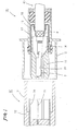
Fig. 1 is a side sectional view showing a state that both
connectors of a first embodiment according to the invention are
separated.
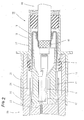
Fig. 2 is a side sectional view of both connectors of the
same under a fitted state.
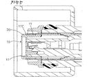
Fig. 3 is a side sectional view showing tip portions of
shield shells provided in both connectors of the same.
Fig. 4 is a side sectional view showing tip portions of
both shield shells of a second embodiment.
Fig. 5 is a side sectional view showing a tip portion of
a shield of a third embodiment.
Fig. 6 is a side sectional view-showing a state that
conventional both female and male connectors are separated.
Fig. 7 is a side sectional view of a fitted state of both
connectors of the same.
Fig. 8 is a side sectional view showing tip portions of
shield shells provided in both connectors of the same.
DETAILED DESCRIPTION OF THE PREFERRED EMBODIMENTS
<First Embodiment>
Hereunder, the first embodiment in which the invention
has been embodied will be described referring to Figs. 1 to 3.
A shield connector of this embodiment is a female
connector 10 shown at a right side of Fig. 1, and to this a mating
male connector 30 at a left side is fitted.
First, the mating male connector 30 has a cavity (not
shown) inside a male side connector housing 32 having a
cylindrical hood portion 31, and a tab 33 of male type terminal
metal fitting accommodated in the cavity protrudes forward from
an inner part of the hood portion 31. At a position surrounding
the cavity, a cylindrical male side shield shell 34 is inserted
into the male side connector housing 32 and mounted thereto.
Further, as shown in Fig. 3, in the male side shield shell 34,
there is formed a taper face 34B along an inner edge of its tip
face 34A within a range of 1/2 of wall thickness t.
On the other hand, the female connector 10 to which the
invention is applied has a female side connector housing 13 in
which a cylindrical hood portion 12 is formed so as to surround
a cylindrical portion 11, a cavity 14 is formed in the
cylindrical portion 11 and a lance 15 corresponding to an
engaging mechanism of the invention is integrally molded in the
cavity 14. Further, a female type terminal metal fitting 9
accommodated in the cavity 14 is prevented from falling off and
maintained by the lance 15.
On an outer surface of the cylindrical portion 11, a
cylindrical female side shield shell 17 surrounding the female
type metal fitting 9 is inserted into the female side connector
housing 13 and mounted thereto. At a rear side of the female
side shield shell 17, an elastic contact piece 18 is extended
toward an inside, and the elastic contact piece 18 is
conductively connected to a shield layer 41 of a shield wire
40 fixed to the female type terminal metal fitting 9. Further,
as shown in Fig. 3, at a front side of the female side shield
shell 17, a taper face 17B is formed along an outer edge of its
tip face 17A within a range of 1/2 of the wall thickness t.
Now, as shown in Fig. 3, at a tip portion of the cylindrical
portion 11 of the female side connector housing 13, a guide
protrusion portion 20 extending in flange-like form toward a
side is provided. The guide protrusion portion 20 is set to
a height covering an inner edge side of the tip face 17A of the
female side shield shell 17. More detailedly, the guide
protrusion portion 20 covers a lower side (lower half of the
wall thickness t of the female side shield shell 17) than the
taper face 17B of the tip face 17A of the female side shield
shell 17.
At a front side of the guide protrusion portion 20, there
is formed an inclined face 21 inclining so as to proceed to an
outside of the female side shield shell 17 as going toward an
inner part of the fitting. An inner edge (refer to a mark P4
in Fig. 3) of the inclined face 21 is positioned inside by a
dimension S1 from an inner edge (refer to a mark P5 in Fig. 3)
of the female side shield shell 17.
Next, an action of this embodiment will be explained.
From a separated state shown in Fig. 1, both connectors 10 and
30 are mutually fitted. Then, as shown in Fig. 2, the hood
portion 31 of the male side connector housing 32 enters into
the hood portion 12 of the female side connector housing 13 and
becomes a fitted state, and the tab 33 of the male type terminal
metal fitting is fitted into the female type terminal metal
fitting 16 and connected thereto. Further, simultaneously
with this, a tip of the male side shield shell 34 is fitted with
a tip outer side of the female side shield shell 17, and both
are electrically connected to each other.
By the way, there is a case where the connectors are
mutually pushed under a state that a fitting position between
the connectors deviates somewhat or that an assembling error
of the shield shell with respect to the connector housing occurs.
When the above deviation of the fitting position or the
assembling error is large, the male side shield shell 34 butts
against the inclined face 21 provided in the guide protrusion
portion 20 of the female connector 10. If the connectors 10
and 30 are pushed under this state, the male side shield shell
34 proceeds toward an outer edge side of the tip face 17A of
the female side shield shell 17 while being guided by the
inclined face 21. Further, the male side shield shell 34 is
guided by the taper face 17B provided in an outer edge portion
of the female side shield shell 17 and reaches a regular position
where axes of both shield shells 17 and 34 coincide with each
other, so that they are pushed as they are to be mutually fitted
and thus electrically connected to each other.
Here, since the guide protrusion portion 20 is provided
in the female side connector housing 13 of the female connector
10, a large guidable range can be ensured without undergoing
a limitation owing to a wall thickness dimension of the shield
shell like in the conventional connector. More concretely, in
the regular position where the axes of both shield shells 17
and 34 coincide with each other, an inner edge (refer to a mark
P1 in Fig. 3)of the taper face 34B provided in the male side
shield shell 34 and an outer edge (refer to a mark P2 in Fig.
3) of the taper face 17B provided in the female side shield shell
17 coincide with each other in a radial direction (vertical
direction in Fig. 3) of the shield shell as shown by the solid
line in Fig. 3. On the other hand, in the maximum deviation
allowable position, as shown in Fig. 3 by the two-dot chain line,
since an outer edge (refer to a mark P3 in Fig. 3) of the taper
face 34B provided in the male side shield shell 34 and an inner
edge (refer to a mark P4 in Fig. 3) of the inclined face 21 of
the guide protrusion portion 20 coincide with each other in the
radial direction of the shield shell, a maximum allowable
deviation amount L2 of the shield shell in this embodiment
becomes 1.5t + S1. Here, the maximum allowable deviation amount
L2 is provided when the taper face 34B is formed within the range
of 1/2 of wall thickness t. Further, by a change of the
dimension S1, it is possible to set the maximum allowable
deviation amount L2 of the shield shell large irrespective of
the wall thickness t of the shield shell. Accordingly, even
if the connectors mutually deviate in some extent or even if
the assembling position of the shield shell scatters with
respect to the connector housing, it follows that an end face
of the shield shell does not butt against the mating side, so
that a fitting operation can be easily performed.
<Second Embodiment>
As shown in Fig. 4, as to this embodiment, the same
structural parts as those in the first embodiment are affixed
with the same reference numerals and duplicated explanations
are omitted, so that only a different constitution will be
explained below.
A tip of the female side shield shell 17 of this embodiment
is doubled by being folded to an inner peripheral side, and the
portion folded to the inner side is covered by the guide
protrusion portion 20. By this, at an outer side than the guide
protrusion portion 20 of the female side shield shell 17, a 1/4
arc guide curved surface 17C for guiding the male side shield
shell 34 to the regular position is formed.
If such a constitution is adopted, a maximum allowable
deviation amount L3 of the male side shield shell 34 becomes
2.5t + S2 as shown in the drawing, and also by a change of the
dimension S2 it is possible to set the maximum allowable
deviation amount irrespective of the wall thickness t of the
shield shell. Here, the maximum allowable deviation amount L3
is provided when the taper face 34B is formed within the range
of 1/2 of wall thickness t.
<Third Embodiment>
As shown in Fig. 5, a tip of the female side shield shell
17 of this embodiment is doubled by being folded to an inner
peripheral side similarly to the second embodiment, and such
a constitution is adopted that the guide protrusion portion 20
covering the portion folded to the inner side is formed
integrally with a double engaging retainer 19 of the female type
terminal metal fitting 9 mounted on the female side connector
housing 13.
According to this embodiment, since the guide protrusion
portion 20 is formed integrally with retainer 19, molds therefor
are prevented from becoming complex in comparison with a case
where the guide protrusion portion 20 is formed in the female
side connector housing 13 whereby an increase in the
manufacturing cost can be prevented.
Incidentally, in this embodiment, although a gap is
provided between a tip face of the female side shield shell 17
and the guide protrusion portion 20, a shield connector of such
a constitution is also contained in the technical scope of the
invention.
<Other Embodiments>
The invention is not limited to the above description and
drawings, and for example the following embodiments are also
contained in the technical scope of the invention and, further,
besides the followings various modifications can be performed
within a scope not departing from gist of the invention.