EP1587080A1 - Method for track jump control - Google Patents
Method for track jump control Download PDFInfo
- Publication number
- EP1587080A1 EP1587080A1 EP04008848A EP04008848A EP1587080A1 EP 1587080 A1 EP1587080 A1 EP 1587080A1 EP 04008848 A EP04008848 A EP 04008848A EP 04008848 A EP04008848 A EP 04008848A EP 1587080 A1 EP1587080 A1 EP 1587080A1
- Authority
- EP
- European Patent Office
- Prior art keywords
- track jump
- sector
- tolerance window
- subcode
- window
- Prior art date
- Legal status (The legal status is an assumption and is not a legal conclusion. Google has not performed a legal analysis and makes no representation as to the accuracy of the status listed.)
- Withdrawn
Links
- 230000003287 optical effect Effects 0.000 claims abstract description 29
- 230000000977 initiatory effect Effects 0.000 claims description 3
Images

Classifications
-
- G—PHYSICS
- G11—INFORMATION STORAGE
- G11B—INFORMATION STORAGE BASED ON RELATIVE MOVEMENT BETWEEN RECORD CARRIER AND TRANSDUCER
- G11B7/00—Recording or reproducing by optical means, e.g. recording using a thermal beam of optical radiation by modifying optical properties or the physical structure, reproducing using an optical beam at lower power by sensing optical properties; Record carriers therefor
- G11B7/08—Disposition or mounting of heads or light sources relatively to record carriers
- G11B7/085—Disposition or mounting of heads or light sources relatively to record carriers with provision for moving the light beam into, or out of, its operative position or across tracks, otherwise than during the transducing operation, e.g. for adjustment or preliminary positioning or track change or selection
- G11B7/08505—Methods for track change, selection or preliminary positioning by moving the head
- G11B7/08517—Methods for track change, selection or preliminary positioning by moving the head with tracking pull-in only
-
- G—PHYSICS
- G11—INFORMATION STORAGE
- G11B—INFORMATION STORAGE BASED ON RELATIVE MOVEMENT BETWEEN RECORD CARRIER AND TRANSDUCER
- G11B7/00—Recording or reproducing by optical means, e.g. recording using a thermal beam of optical radiation by modifying optical properties or the physical structure, reproducing using an optical beam at lower power by sensing optical properties; Record carriers therefor
- G11B7/08—Disposition or mounting of heads or light sources relatively to record carriers
- G11B7/09—Disposition or mounting of heads or light sources relatively to record carriers with provision for moving the light beam or focus plane for the purpose of maintaining alignment of the light beam relative to the record carrier during transducing operation, e.g. to compensate for surface irregularities of the latter or for track following
-
- G—PHYSICS
- G11—INFORMATION STORAGE
- G11B—INFORMATION STORAGE BASED ON RELATIVE MOVEMENT BETWEEN RECORD CARRIER AND TRANSDUCER
- G11B7/00—Recording or reproducing by optical means, e.g. recording using a thermal beam of optical radiation by modifying optical properties or the physical structure, reproducing using an optical beam at lower power by sensing optical properties; Record carriers therefor
- G11B7/08—Disposition or mounting of heads or light sources relatively to record carriers
- G11B7/085—Disposition or mounting of heads or light sources relatively to record carriers with provision for moving the light beam into, or out of, its operative position or across tracks, otherwise than during the transducing operation, e.g. for adjustment or preliminary positioning or track change or selection
Definitions
- the present invention relates to a method for controlling a track jump on an optical recording medium, and to an apparatus for reading from and/or writing to optical recording media using such method.
- Each sector or subcode has an ID, which is a number that increments along the data stream.
- ID is a number that increments along the data stream.
- track jumps In order to perform a track jump to the requested target sector or subcode of an optical recording medium the number of tracks to jump is first calculated based on the difference between the currently played back sector or subcode and the requested sector or subcode.
- a playback control mechanism compares the first successfully read sector or subcode ID with the desired target sector or subcode.
- the playback control mechanism only switches from jump mode to playback mode if the first successfully read sector or subcode is the target sector or subcode or one within a small tolerance range before that target sector or subcode.
- a tolerance window is defined from sector or subcode number n-m to sector or subcode number n , where n is the target sector or subcode and m is a number of subcodes or sectors usually in the order of one track, i.e. one revolution of the optical recording medium.
- this object is achieved by a method for track jump control for an optical recording medium including the steps of defining a first tolerance window adjacent to a target position on the optical recording medium, and after finishing a track jump, reading a sector or subcode on the optical recording medium, which further includes the steps of:
- the method further includes the steps of:
- the time when the track jump was finished is noted, and the actual landing sector or subcode is calculated based on the sector or subcode read after finishing the track jump and the time passed since the track jump was finished until the sector or subcode was read. Based on the time that has passed since the track jump was finished until the sector or subcode was read the actual landing sector or subcode can easily be calculated when the rotation speed of the optical recording medium is known, which is generally the case since the rotation speed has to be controlled anyway for playback or recording. Of course, it is also possible to assume a fixed delay between the finishing of the track jump and the reading of the sector or subcode, and to use this delay for calculating the actual landing sector or subcode.
- the method further includes the step of initiating an additional track jump in case neither the sector or subcode read after finishing the track jump nor the actual landing sector or subcode lie within the second tolerance window. This is the case, for example, when the actual landing sector or subcode lies within the first tolerance window. In this case the system will not be settled when the target position is reached and the playback or recording operation is resumed. Therefore, an additional track jump is necessary to reach the desired target position.
- an additional track jump is initiated in case the sector or subcode read after finishing the track jump neither lies within the second tolerance window nor within the first tolerance window.
- the read sector or subcode may lie before the second tolerance window.
- an additional track jump is performed since it would require too much time to just wait until the target position is reached.
- the read sector or subcode may lie after the first tolerance window. In this case the target position has already been missed and an additional track jump is necessary to reach the desired target position.
- first and/or second tolerance windows are defined for different types of optical recording media, for different playback or recording speeds, and/or for different operating conditions.
- a rewritable recording medium might need larger tolerance windows than a recordable or recorded recording medium.
- a low-density recording medium such as a Compact Disc might need smaller tolerance windows than a high-density recording medium such as a Digital Versatile Disk.
- different tolerance windows might be suitable for different operating conditions such as playback and recording.
- the quality of the optical recording medium is determined and the first and/or the second tolerance window is defined in accordance with the determined quality.
- the quality is advantageously determined before the playback or recording operation is initiated, e.g. when the recording medium is inserted in a playback or recording apparatus.
- the quality can also be determined on the fly, i.e. during the playback or recording operation.
- a track jump controller includes means for performing a method according to the invention for track jump control.
- Such a track jump controller is especially advantageous for low cost systems or for critical optical recording media.
- an apparatus for reading from and/or writing to optical recording media performs a method or includes a track jump controller according to the invention for track jump control.
- Such an apparatus has an increased track jump performance.
- Fig. 1 shows an optical recording medium 1 with a spiral data track 2.
- two tolerance windows are defined on a sector or subcode basis related to the target sector or subcode: a servo jump window 6 and a system settle window 7.
- the tolerance windows are depicted in more detail in Fig. 2.
- the system settle window 7 is in a range n-m to n subcodes or sectors, while the servo jump window 6 is in the range n-l to n- ( m+1 ) subcodes or sectors.
- n is the target sector or subcode
- m and l are positive numbers with l being larger than m and m being larger than 0.
- the data track may also be arranged in concentric circles. In this case, however, the servo jump window 6 and the system settle window 7 in combination may not exceed one rotation of the optical recording medium 1.
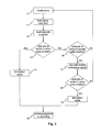
- FIG. 3 A flow chart of the method for track jump control according to the invention is illustrated in Fig. 3.
- a track jump is initiated 10 and finished 11 the time when the track jump is finished is noted 11.
- a first sector or subcode is successfully read 12 it is checked 13 if the read sector or subcode is within the servo jump window 6. If this is the case, the system is allowed to settle 14 for the remainder of the servo jump window 6 plus the entire system settle window 7 before the playback or recording operation is resumed 15 once the target sector or subcode is reached. If, however, the first successfully read sector or subcode is not within the servo jump window 6, it is checked 16 if it is within the system settle window 7. If this is not the case, a further track jump needs to be initiated 10.
- the sector or subcode where the jump was ended is calculated 17 based on the first successfully read sector or subcode and the time that has expired since the servo jump was ended 11. It is then checked 18 if the calculated sector or subcode is within the servo jump window 6. If this is true, the track jump operation is considered successful in the sense that the track jump actually ended within the servo jump window 6 and the system is allowed to settle 19 for the remainder of the system settle window 7 before the playback or recording operation is resumed 15 once the target sector or subcode is reached. Otherwise a further track jump is initiated 10.
Landscapes
- Moving Of The Head For Recording And Reproducing By Optical Means (AREA)
- Optical Recording Or Reproduction (AREA)
- Signal Processing For Digital Recording And Reproducing (AREA)
Abstract
The present invention relates to a method for controlling a
track jump on an optical recording medium (1), and to an
apparatus for reading from and/or writing to optical
recording media (1) using such method.
According to the invention a method for track jump control
includes the steps of:
- defining a first tolerance window (7) adjacent to a target position (3) on the optical recording medium (1),
- defining a second tolerance window (6) adjacent to the first tolerance window (7),
- after finishing (11) a track jump, reading (12) a sector or subcode on the optical recording medium (1),
- if the sector or subcode read (12) after finishing (11) the track jump lies (13) within the second tolerance window (6), determining that the track jump was finished (11) within the second tolerance window (6),
- if the track jump was finished (11) within the second tolerance window (6), letting the system settle (14) for the remainder of the second tolerance window (6) plus the first tolerance window (7), and
- resuming (15) the playback or recording operation at the target position (3).
Description
The present invention relates to a method for controlling a
track jump on an optical recording medium, and to an
apparatus for reading from and/or writing to optical
recording media using such method.
On optical recording media data are stored along spiral
tracks. In order to enable random access to specific data, so
called sector or subcode information is embedded in the data
stream. Each sector or subcode has an ID, which is a number
that increments along the data stream. During playback and/or
recording of optical recording media it is often necessary to
jump from one location on the recording medium to another
location on the recording medium. Those jumps to a desired
target sector or subcode are referred to as track jumps. In
order to perform a track jump to the requested target sector
or subcode of an optical recording medium the number of
tracks to jump is first calculated based on the difference
between the currently played back sector or subcode and the
requested sector or subcode. When a track jump is completed
servo-wise, a playback control mechanism compares the first
successfully read sector or subcode ID with the desired
target sector or subcode. The playback control mechanism only
switches from jump mode to playback mode if the first
successfully read sector or subcode is the target sector or
subcode or one within a small tolerance range before that
target sector or subcode. In other words, for the target of
the track jump a tolerance window is defined from sector or
subcode number n-m to sector or subcode number n, where n is
the target sector or subcode and m is a number of subcodes or
sectors usually in the order of one track, i.e. one
revolution of the optical recording medium. A problem with
this approach, especially in low cost systems and/or with
critical optical recording media, is that once the track jump
is finished servo-wise, it takes a little time for the
optical mechanism to settle. This may be perceived as
incorrect data once playback indicates that the requested
target is reached though the system is not settled, or it may
require a number of additional iteration track jumps.
It is, therefore, an object of the invention to propose an
improved method for track jump control, which overcomes the
above mentioned drawbacks.
According to the invention, this object is achieved by a
method for track jump control for an optical recording medium
including the steps of defining a first tolerance window
adjacent to a target position on the optical recording
medium, and after finishing a track jump, reading a sector or
subcode on the optical recording medium, which further
includes the steps of:
- defining a second tolerance window adjacent to the first tolerance window,
- if the sector or subcode read after finishing the track jump lies within the second tolerance window, determining that the track jump was finished within the second tolerance window,
- if the track jump was finished within the second tolerance window, letting the system settle for the remainder of the second tolerance window plus the first tolerance window, and
- resuming the playback or recording operation at the target position.
Favourably, the method further includes the steps of:
- if the sector or subcode read after finishing the track jump lies within the first tolerance window, calculating an actual landing sector or subcode to check if the track jump was actually finished within the second tolerance window, and
- if the track jump was actually finished within the second tolerance window, letting the system settle for the remainder of the first tolerance window.
Advantageously after finishing the track jump the time when
the track jump was finished is noted, and the actual landing
sector or subcode is calculated based on the sector or
subcode read after finishing the track jump and the time
passed since the track jump was finished until the sector or
subcode was read.
Based on the time that has passed since the track jump was finished until the sector or subcode was read the actual landing sector or subcode can easily be calculated when the rotation speed of the optical recording medium is known, which is generally the case since the rotation speed has to be controlled anyway for playback or recording. Of course, it is also possible to assume a fixed delay between the finishing of the track jump and the reading of the sector or subcode, and to use this delay for calculating the actual landing sector or subcode.
Based on the time that has passed since the track jump was finished until the sector or subcode was read the actual landing sector or subcode can easily be calculated when the rotation speed of the optical recording medium is known, which is generally the case since the rotation speed has to be controlled anyway for playback or recording. Of course, it is also possible to assume a fixed delay between the finishing of the track jump and the reading of the sector or subcode, and to use this delay for calculating the actual landing sector or subcode.
Favourably the method further includes the step of initiating
an additional track jump in case neither the sector or
subcode read after finishing the track jump nor the actual
landing sector or subcode lie within the second tolerance
window.
This is the case, for example, when the actual landing sector or subcode lies within the first tolerance window. In this case the system will not be settled when the target position is reached and the playback or recording operation is resumed. Therefore, an additional track jump is necessary to reach the desired target position.
This is the case, for example, when the actual landing sector or subcode lies within the first tolerance window. In this case the system will not be settled when the target position is reached and the playback or recording operation is resumed. Therefore, an additional track jump is necessary to reach the desired target position.
Advantageously an additional track jump is initiated in case
the sector or subcode read after finishing the track jump
neither lies within the second tolerance window nor within
the first tolerance window. For example, the read sector or
subcode may lie before the second tolerance window. In this
case an additional track jump is performed since it would
require too much time to just wait until the target position
is reached. Alternatively, the read sector or subcode may lie
after the first tolerance window. In this case the target
position has already been missed and an additional track jump
is necessary to reach the desired target position.
Preferably, different first and/or second tolerance windows
are defined for different types of optical recording media,
for different playback or recording speeds, and/or for
different operating conditions. For example, a rewritable
recording medium might need larger tolerance windows than a
recordable or recorded recording medium. Similarly, a low-density
recording medium such as a Compact Disc might need
smaller tolerance windows than a high-density recording
medium such as a Digital Versatile Disk. Also different
tolerance windows might be suitable for different operating
conditions such as playback and recording.
According to a further refinement of the invention, including
the quality of the optical recording medium is determined and
the first and/or the second tolerance window is defined in
accordance with the determined quality. This allows to adapt
the tolerance windows to the specific recording medium and
helps to avoid exceedingly large tolerance windows in case of
recording media having a good quality. The quality is
advantageously determined before the playback or recording
operation is initiated, e.g. when the recording medium is
inserted in a playback or recording apparatus. However, the
quality can also be determined on the fly, i.e. during the
playback or recording operation.
Preferably a track jump controller includes means for
performing a method according to the invention for track jump
control. Such a track jump controller is especially
advantageous for low cost systems or for critical optical
recording media.
Advantageously, an apparatus for reading from and/or writing
to optical recording media performs a method or includes a
track jump controller according to the invention for track
jump control. Such an apparatus has an increased track jump
performance.
For a better understanding of the invention, exemplary
embodiments are specified in the following description with
reference to the figures. It is understood that the invention
is not limited to these exemplary embodiments and that
specified features can also expediently be combined and/or
modified without departing from the scope of the present
invention. In the figures:
Fig. 1 shows an optical recording medium 1 with a spiral data
track 2. For a track jump to a target sector or subcode n two
tolerance windows are defined on a sector or subcode basis
related to the target sector or subcode: a servo jump window
6 and a system settle window 7. The tolerance windows are
depicted in more detail in Fig. 2. For simplicity in Fig. 2
the track is drawn as a linear track. The system settle
window 7 is in a range n-m to n subcodes or sectors, while
the servo jump window 6 is in the range n-l to n-(m+1)
subcodes or sectors. Here n is the target sector or subcode,
m and l are positive numbers with l being larger than m and
m being larger than 0. Instead of a spiral data track, the
data track may also be arranged in concentric circles. In
this case, however, the servo jump window 6 and the system
settle window 7 in combination may not exceed one rotation of
the optical recording medium 1.
A flow chart of the method for track jump control according
to the invention is illustrated in Fig. 3. When a track jump
is initiated 10 and finished 11 the time when the track jump
is finished is noted 11. When a first sector or subcode is
successfully read 12 it is checked 13 if the read sector or
subcode is within the servo jump window 6. If this is the
case, the system is allowed to settle 14 for the remainder of
the servo jump window 6 plus the entire system settle window
7 before the playback or recording operation is resumed 15
once the target sector or subcode is reached. If, however,
the first successfully read sector or subcode is not within
the servo jump window 6, it is checked 16 if it is within the
system settle window 7. If this is not the case, a further
track jump needs to be initiated 10. If the read sector or
subcode is within the system settle window 7, the sector or
subcode where the jump was ended is calculated 17 based on
the first successfully read sector or subcode and the time
that has expired since the servo jump was ended 11. It is
then checked 18 if the calculated sector or subcode is within
the servo jump window 6. If this is true, the track jump
operation is considered successful in the sense that the
track jump actually ended within the servo jump window 6 and
the system is allowed to settle 19 for the remainder of the
system settle window 7 before the playback or recording
operation is resumed 15 once the target sector or subcode is
reached. Otherwise a further track jump is initiated 10.
Claims (9)
- Method for track jump control for an optical recording medium (1) including the steps of:characterized in that it further includes the steps of:defining a first tolerance window (7) adjacent to a target position (3) on the optical recording medium (1), andafter finishing (11) a track jump, reading (12) a sector or subcode on the optical recording medium (1),defining a second tolerance window (6) adjacent to the first tolerance window (7),if the sector or subcode read (12) after finishing (11) the track jump lies (13) within the second tolerance window (6), determining that the track jump was finished (11) within the second tolerance window (6),if the track jump was finished (11) within the second tolerance window (6), letting the system settle (14) for the remainder of the second tolerance window (6) plus the first tolerance window (7), andresuming (15) the playback or recording operation at the target position (3).
- Method according to claim 1, further including the steps of:if the sector or subcode read (12) after finishing (11) the track jump lies (16) within the first tolerance window (7), calculating (17) an actual landing sector or subcode to check (18) if the track jump was actually finished (11) within the second tolerance window (6), andif the track jump was actually finished (11) within the second tolerance window (6), letting the system settle (19) for the remainder of the first tolerance window (7).
- Method according to claim 2, wherein after finishing the track jump the time when the track jump was finished is noted (11), and the actual landing sector or subcode is calculated based on the sector or subcode read (12) after finishing (11) the track jump and the time passed since the track jump was finished (11) until the sector or subcode was read.
- Method according to one of claims 1 to 3, further including the step of initiating an additional track jump in case neither the sector or subcode read (12) after finishing (11) the track jump nor the actual landing sector or subcode lie within the second tolerance window (6).
- Method according to claim 4, further including the step of initiating an additional track jump in case the sector or subcode read (12) after finishing (11) the track jump neither lies within the second tolerance window (6) nor within the first tolerance window (7).
- Method according to one of claims 1 to 5, wherein different first and/or second tolerance windows (6, 7) are defined for different types of optical recording media (1), for different playback or recording speeds, and/or for different operating conditions.
- Method according to one of claims 1 to 6, further including the steps of determining the quality of the optical recording medium (1) and defining the first and/or the second tolerance window (6, 7) in accordance with the determined quality.
- Track jump controller, characterized in that it includes means for performing a method according to one of claims 1 to 7 for track jump control.
- Apparatus for reading from and/or writing to optical recording media (1), characterized in that it performs a method according to one of claims 1 to 7 or includes a track jump controller according to claim 8 for track jump control.
Priority Applications (9)
| Application Number | Priority Date | Filing Date | Title |
|---|---|---|---|
| EP04008848A EP1587080A1 (en) | 2004-04-14 | 2004-04-14 | Method for track jump control |
| EP05300213A EP1587081A3 (en) | 2004-04-14 | 2005-03-23 | Method for track jump control |
| US11/096,674 US20050232098A1 (en) | 2004-04-14 | 2005-04-01 | Method for track jump control |
| TW094111089A TW200534257A (en) | 2004-04-14 | 2005-04-08 | Method for track jump control |
| KR1020050029391A KR20060046641A (en) | 2004-04-14 | 2005-04-08 | Track jump control method |
| MYPI20051591A MY146135A (en) | 2004-04-14 | 2005-04-11 | Method for track jump control |
| JP2005115693A JP2005302284A (en) | 2004-04-14 | 2005-04-13 | Track jump control method |
| CNA2005100641868A CN1684159A (en) | 2004-04-14 | 2005-04-13 | Track jump control method |
| US11/106,013 US20050232029A1 (en) | 2004-04-14 | 2005-04-13 | Write pulse generation for recording on optical media |
Applications Claiming Priority (1)
| Application Number | Priority Date | Filing Date | Title |
|---|---|---|---|
| EP04008848A EP1587080A1 (en) | 2004-04-14 | 2004-04-14 | Method for track jump control |
Publications (1)
| Publication Number | Publication Date |
|---|---|
| EP1587080A1 true EP1587080A1 (en) | 2005-10-19 |
Family
ID=34924593
Family Applications (1)
| Application Number | Title | Priority Date | Filing Date |
|---|---|---|---|
| EP04008848A Withdrawn EP1587080A1 (en) | 2004-04-14 | 2004-04-14 | Method for track jump control |
Country Status (7)
| Country | Link |
|---|---|
| US (2) | US20050232098A1 (en) |
| EP (1) | EP1587080A1 (en) |
| JP (1) | JP2005302284A (en) |
| KR (1) | KR20060046641A (en) |
| CN (1) | CN1684159A (en) |
| MY (1) | MY146135A (en) |
| TW (1) | TW200534257A (en) |
Families Citing this family (1)
| Publication number | Priority date | Publication date | Assignee | Title |
|---|---|---|---|---|
| CN113227935B (en) * | 2018-10-24 | 2024-09-13 | 奇跃公司 | Asynchronous ASIC |
Citations (4)
| Publication number | Priority date | Publication date | Assignee | Title |
|---|---|---|---|---|
| EP0348949A2 (en) * | 1988-06-28 | 1990-01-03 | Nec Corporation | Disc control apparatus |
| US5315568A (en) * | 1992-11-12 | 1994-05-24 | International Business Machines Corporation | Apparatus and method for accessing sectors of a rotating disk |
| US20010028613A1 (en) * | 2000-04-10 | 2001-10-11 | Yutaka Okamoto | Optical disk, optical disk apparatus, and optical disk tracking error determination method |
| US6426843B1 (en) * | 1999-04-27 | 2002-07-30 | International Business Machines Corporation | Settle time estimator feedback for rotational position reordering in data storage devices |
Family Cites Families (7)
| Publication number | Priority date | Publication date | Assignee | Title |
|---|---|---|---|---|
| US3473160A (en) * | 1966-10-10 | 1969-10-14 | Stanford Research Inst | Electronically controlled microelectronic cellular logic array |
| JPH0725917Y2 (en) * | 1989-10-27 | 1995-06-07 | 三洋電機株式会社 | Tape recorder device |
| JPH10293926A (en) * | 1997-02-21 | 1998-11-04 | Pioneer Electron Corp | Recording clock signal generating device |
| US6111712A (en) * | 1998-03-06 | 2000-08-29 | Cirrus Logic, Inc. | Method to improve the jitter of high frequency phase locked loops used in read channels |
| US6218876B1 (en) * | 1999-01-08 | 2001-04-17 | Altera Corporation | Phase-locked loop circuitry for programmable logic devices |
| JP4098477B2 (en) * | 2001-01-25 | 2008-06-11 | パイオニア株式会社 | Information reproducing apparatus and transversal filter |
| JP2004072714A (en) * | 2002-06-11 | 2004-03-04 | Rohm Co Ltd | Clock generating system |
-
2004
- 2004-04-14 EP EP04008848A patent/EP1587080A1/en not_active Withdrawn
-
2005
- 2005-04-01 US US11/096,674 patent/US20050232098A1/en not_active Abandoned
- 2005-04-08 TW TW094111089A patent/TW200534257A/en unknown
- 2005-04-08 KR KR1020050029391A patent/KR20060046641A/en not_active Withdrawn
- 2005-04-11 MY MYPI20051591A patent/MY146135A/en unknown
- 2005-04-13 JP JP2005115693A patent/JP2005302284A/en not_active Ceased
- 2005-04-13 US US11/106,013 patent/US20050232029A1/en not_active Abandoned
- 2005-04-13 CN CNA2005100641868A patent/CN1684159A/en active Pending
Patent Citations (4)
| Publication number | Priority date | Publication date | Assignee | Title |
|---|---|---|---|---|
| EP0348949A2 (en) * | 1988-06-28 | 1990-01-03 | Nec Corporation | Disc control apparatus |
| US5315568A (en) * | 1992-11-12 | 1994-05-24 | International Business Machines Corporation | Apparatus and method for accessing sectors of a rotating disk |
| US6426843B1 (en) * | 1999-04-27 | 2002-07-30 | International Business Machines Corporation | Settle time estimator feedback for rotational position reordering in data storage devices |
| US20010028613A1 (en) * | 2000-04-10 | 2001-10-11 | Yutaka Okamoto | Optical disk, optical disk apparatus, and optical disk tracking error determination method |
Also Published As
| Publication number | Publication date |
|---|---|
| CN1684159A (en) | 2005-10-19 |
| US20050232098A1 (en) | 2005-10-20 |
| US20050232029A1 (en) | 2005-10-20 |
| MY146135A (en) | 2012-06-29 |
| TW200534257A (en) | 2005-10-16 |
| JP2005302284A (en) | 2005-10-27 |
| KR20060046641A (en) | 2006-05-17 |
Similar Documents
| Publication | Publication Date | Title |
|---|---|---|
| US6101065A (en) | Disk drive with seek profile selection based on read/write operation | |
| EP1607967B1 (en) | Information recording method, information recording apparatus and program for writing data to a multilayer recording medium | |
| JP4713839B2 (en) | Optical disc apparatus and focus jump control method thereof | |
| US20050232098A1 (en) | Method for track jump control | |
| EP1587081A2 (en) | Method for track jump control | |
| JP2000251269A (en) | Information recording / reproducing apparatus and method, and transmission medium | |
| CN1816851A (en) | Recording method and apparatus for recording information on a dual-layer recordable disc | |
| EP1758114A2 (en) | Data storage device and a method of controlling write of user data thereof | |
| EP0840298B1 (en) | Reproduction apparatus and methods for recording media | |
| US7099106B2 (en) | Deceleration of head in disc drive according to a desired deceleration profile | |
| US20060279870A1 (en) | Method of controlling track seek in HDD and a recording medium therefor | |
| US7203016B2 (en) | Method of reproducing data and control device using controllable dummy read gate | |
| JP2011008889A (en) | Method of playing back optical disk | |
| JP4822678B2 (en) | Optical disc apparatus and access control method thereof | |
| US9595287B2 (en) | Recording and reproducing apparatus | |
| JP4484114B2 (en) | Motor drive control device | |
| JPH08221917A (en) | Optical disc high speed access device | |
| JP2002304750A (en) | Optical disk drive | |
| US20080239892A1 (en) | Method and System for Recording Data on an Optical Disc by a Plurality of Laser Beams | |
| JP2007287252A (en) | Erase method for disc recording surface | |
| JP2005166142A (en) | Disc reproducing apparatus, pickup position specifying method and pickup moving method | |
| CN101162601A (en) | Optical disc device and optical disc recording and reproducing method | |
| JP2002008252A (en) | Optical disk device and optical disk access control method | |
| US20070121441A1 (en) | Optical disk recording/reproducing apparatus and seek control method thereof | |
| JPH0916980A (en) | Information access method for clv optical disk |
Legal Events
| Date | Code | Title | Description |
|---|---|---|---|
| PUAI | Public reference made under article 153(3) epc to a published international application that has entered the european phase |
Free format text: ORIGINAL CODE: 0009012 |
|
| AK | Designated contracting states |
Kind code of ref document: A1 Designated state(s): AT BE BG CH CY CZ DE DK EE ES FI FR GB GR HU IE IT LI LU MC NL PL PT RO SE SI SK TR |
|
| AX | Request for extension of the european patent |
Extension state: AL HR LT LV MK |
|
| AKX | Designation fees paid | ||
| STAA | Information on the status of an ep patent application or granted ep patent |
Free format text: STATUS: THE APPLICATION IS DEEMED TO BE WITHDRAWN |
|
| 18D | Application deemed to be withdrawn |
Effective date: 20060420 |
|
| REG | Reference to a national code |
Ref country code: DE Ref legal event code: 8566 |