EP1587035A1 - Réduction des artefacts parasites pour rendre les graphics 2.5D - Google Patents
Réduction des artefacts parasites pour rendre les graphics 2.5D Download PDFInfo
- Publication number
- EP1587035A1 EP1587035A1 EP04101511A EP04101511A EP1587035A1 EP 1587035 A1 EP1587035 A1 EP 1587035A1 EP 04101511 A EP04101511 A EP 04101511A EP 04101511 A EP04101511 A EP 04101511A EP 1587035 A1 EP1587035 A1 EP 1587035A1
- Authority
- EP
- European Patent Office
- Prior art keywords
- image
- input
- pixel
- output
- pixels
- Prior art date
- Legal status (The legal status is an assumption and is not a legal conclusion. Google has not performed a legal analysis and makes no representation as to the accuracy of the status listed.)
- Withdrawn
Links
Images


Classifications
-
- G—PHYSICS
- G06—COMPUTING; CALCULATING OR COUNTING
- G06T—IMAGE DATA PROCESSING OR GENERATION, IN GENERAL
- G06T15/00—3D [Three Dimensional] image rendering
- G06T15/10—Geometric effects
- G06T15/20—Perspective computation
Definitions
- This invention relates to an image processing system for generating at least one output image associated with an output viewpoint from an input image associated with an input viewpoint through a depth-dependent transformation, the images being represented as an input pixel array and an output pixel array, respectively.
- This invention further relates to a method and a computer program product.
- both output images are presented simultaneously to one or two displays.
- both images may be filtered with complementary colors and superimposed on one display.
- the observer wears glasses with filters that match the projection filters.
- both images may be displayed alongside on one display and viewed using a viewer which directs each image to the correct eye.
- two displays may be used to present two differently polarized pictures, which are viewed through correspondingly polarized glasses.
- both images may be presented using a head-mounted device with separate displays for each eye.
- time-multiplexed techniques may be used, where the left and right images are alternatingly displayed on one display.
- one image is written to the even scan lines of a monitor and the other image to the odd scan lines.
- a shutter system is used to occlude the left eye when the right-eye image is displayed and to occlude the right eye when the left-eye image is displayed.
- the shutter system may be mounted in glasses worn by the observer.
- a shutter with a controllable polarizer is placed in front of the display and the observer wears a head-mounted device with polarized glasses.
- a possible video format that is suited for rendering a 2D image from different viewpoints is a 2D video format enriched with depth information.
- the 2D input image is given in the form of an array of pixels. It may, for instance, have been obtained using a camera or computer graphics. For each of the pixels of the input image additional depth information is available or, similarly, for each point in the scene, a distance is given of the point to the camera (or to another reference point, line or plane, such as a projection screen).
- Such a format is usually referred to as a 2.5D video format.
- the depth information allows modeling of the original image as a set of samples of a flat image, but also as a set of samples of an image projected onto a terrain.
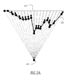
- Fig.2A shows a cross section of the sampled terrain. From the camera position a ray is cast to each pixel of the screen. The lengths of the arrows along the rays indicate the depth values of the pixel samples, also referred to as texels (texture elements).
- the 2.5D video format represents a subset of the full 3D model of the world. Rendering from other viewpoints can be accomplished by projecting the terrain onto the image plane from the desired viewpoint. Based on the parallax when observing the same object from the visual point of the eyes and from the camera point, the pixels of the left eye image and the right eye image can be derived from the pixels of the input image by shifting the pixels.
- an image processing system as described in the first paragraph comprising: an input for receiving the input image and a hidden image, a video processor being operative to create output pixels of the output image and an output for providing the output image for subsequent rendering.
- the input image is a pre-filtered 2D representation of 3D objects as seen from the input viewpoint and comprises for each input pixel an associated input pixel value and an associated input pixel depth.
- the hidden image is another 2D representation of the 3D objects and comprises information, which information is at least partly occluded from the input viewpoint.
- the video processor is operative to create the output pixels by transforming each input pixel to a transformed input pixel, associated with the output viewpoint, as a function of the input pixel depth and creating the output image based on the transformed input pixels, using hidden image pixels for filling de-occluded areas and for at least one pixel position adjacent to the de-occluded areas for preventing ghost line artifacts, caused by transformation of the pre-filtered input image.
- the input image may, for example, be obtained from the input viewpoint by a video camera and the hidden image may then be obtained from a viewpoint, different from the input viewpoint, by another camera.
- the input image and the hidden image may, for example, also be computer generated based on a 3D model of a particular scene.
- the hidden image may be a complete 2D representation of the 3D scene, as seen from a given viewpoint.
- the hidden image may also comprise only information, which information is occluded from the output viewpoint, and is required for only one or a few predetermined transformations.
- De-occlusion may occur at depth discontinuities in the input image. Due to pre-filtering of the camera that records the original video, the pixels in the vicinity of the depth discontinuity contain color from both the foreground and the background objects in the input image. Therefore, simply filling the hole with de-occluded pixels from the hidden layer will result in a noticeable ghost line artifact. It is an advantage of the image processing system according to the invention that ghost line artifacts near the de-occluded hidden image pixels are prevented. This advantage is obtained by rendering a larger part of the hidden layer for replacing transformed input pixels adjacent to the de-occluded parts of the hidden layer. The hidden image pixels in the larger part of the hidden layer are inserted into the output image instead of the corresponding transformed input pixels.
- the depth-dependent transformation is a transformation from the input viewpoint to a predetermined output viewpoint and the hidden image is associated with the output viewpoint.
- the predetermined distance may for example be a distance between a left and a right eye for providing a depth sensation.
- the input image may be obtained by a first camera in a position of a left eye viewpoint and the hidden image by a second camera in a position of a right eye viewpoint. Not all information recorded by the second camera has to be stored in the hidden image. Only information in and adjacent to the areas that are de-occluded with a transformation from the left eye input viewpoint to the right eye output viewpoint has to be stored in the hidden image. After transformation of the input image, this information is used to fill the de-occluded areas in the output image and to prevent ghost line artifacts near the de-occluded areas.
- the hidden image is associated with the input viewpoint and the hidden image pixels are associated with a hidden image pixel value and a hidden image pixel depth
- the video processor being operative to transform each hidden image pixel to a transformed hidden image pixel, associated with the output viewpoint, as a function of the hidden image pixel depth, and to create the output image using transformed hidden image pixels for filling de-occluded areas and for at least one pixel position adjacent to the de-occluded areas.
- This embodiment is particularly useful for providing the possibility to perform various transformations over various distances.
- the input image may be obtained from a first viewpoint by a first camera and the hidden image from a second viewpoint by a second camera.
- the information recorded by the second camera is then transformed to the first viewpoint.
- the input image and the hidden image are thus associated with the same viewpoint. From this viewpoint both images may undergo the same transformation to an arbitrary output viewpoint.
- the image processing system comprises pixel selection means for sequentially selecting input pixels per row.
- the pixel selecting means are arranged for selecting a hidden image pixel for pixel positions in a de-occluded area, for a first number of pixel positions before the de-occluded area and for a second number of pixels after the de-occluded area. For other pixel positions on the display line, transformed input pixels are selected.
- the first and/or second number of pixel positions may depend on a width of a horizontal pre-filter, used during recording of the input image or may be determined based on an analysis of the input image.
- Sequentially processing the pixels per row in a direction opposite a displacement from the input viewpoint to the output viewpoint makes it easy to detect occlusion. This can be done by maintaining an x-coordinate extent indicating a furthest x-coordinate of the pixels and their footprints that have been transformed so far. If the transformation of the next footprint results in increasing the extent the transformed next footprint is at least partly not occluded. In this way it can be decided easily whether or not to exclude a pixel from the output image.
- the x-axis is horizontal and the camera displacement also. If so desired, other directions are possible as well.
- the video processor is operative to determine that a hidden image pixel is de-occluded if a transformed input pixel increases the x-coordinate extent by more than a predetermined threshold.
- a predetermined threshold Preferably, if the x-coordinate of the input pixel after transformation is more than 1.5 pixels away from the last pixel position in the output image, the hole is too big and is filled with at least one pixel from the hidden layer. Since it is desired to use pixels from the hidden layer for pixel positions before the de-occluded area, a means is needed to detect the de-occlusion before the transformed input pixels of the input image are enclosed in the output image. Backtracking is usually not possible because color values are accumulated in the video filter. For early detection of the de-occluded area, the video processing may include maintaining a look ahead extent.
- FIG. 1 shows a block diagram of a conventional system in which the image processing system according to the invention may advantageously be used.
- the conventional system comprises a memory 100, such as a graphics memory, for storing a 2D input image 101.
- the input image 101 is comprised of an array of pixels divided in rows and columns. For each pixel a pixel value is given.
- Various ways of representing a pixel value are well known, such as an RGB (Red, Green, Blue) or YUV coding.
- the pixel value may be stored in full, e.g. using 16 or 24 bits per pixel.
- a Color Look-Up Table (CLUT) scheme may be used to code the pixel value using fewer bits, e.g. 8 bits.
- CLUT Color Look-Up Table
- a depth value is stored in the memory 100 as the input depth 102.
- the depth value may, for instance, be stored using 16 bits per pixel. If required, a separate memory may be used for storing the input depth 102.
- the input image 101 and the input depth 102 may be generated in any suitable way. As an example, two cameras located at different positions may be used, preferably each representing a different eye. From the two 2D-images obtained by the cameras, one image plus depth information can be formed.
- the depth information can then be supplied in addition to and, preferably, compatible with the conventional supply of only one 2D image, allowing the scene to be observed using either a conventional 2D display system or a stereoscopic display system.
- the input image 101 and the input depth 102 are usually generated by a 3D-rendering process which derives the information from a 3D model stored in a memory.
- the memory is part of the main memory of the computer.
- Communication means such as a telecommunication means, audio/video broadcasting or a cable network, may be used to supply the input image 101 and the input depth 102 to the image processing system.
- a processor 106 uses the input image 101 and the input depth 102 to generate at least one output image.
- a left image 107 and a right image 108 are generated.
- the left image 107 represents a 2D representation of the 3D scene as observed from an observation point coinciding with the left eye of an observer.
- the right image 108 represents a 2D representation of the 3D scene as observed from an observation point coinciding with the right eye of an observer.
- the processor 106 may build the output images in a memory 109, such as a graphics memory.
- the system according to the invention enables processing per pixel row, reducing the memory requirements.
- the memories can therefore be formed using line buffers for storing only one scan line of an image.
- the image data can be processed as stream. If vertical filtering is applied, a few rows need to be stored.
- a D/A converter 110 presents the output images on a suitable display 111, such as a stereoscopic display.
- the processor 106 may operate on the input image and input depth time-synchronized at pixel level to the supply of this information. The synchronization may be loosened by using a memory 103 for storing an input image 104 and input depth 105, being a respective copy of the input image 101 and input depth 102. The processor 106 then operates on the input image 104 and input depth 105, independent from the supply of the input image 101 and input depth 102. At suitable moments, e.g.
- the input image 101 and the input depth 102 are copied to the respective input image 104 and input depth 105.
- the copying may be performed without physically copying the data, for instance by reassigning pointer registers. It will be appreciated that instead for maintaining a full image copy also a few pixels of a row or a few rows may be stored depending on the filter being applied.
- the depth dependent transformation of the input image into the output image is associated with displacements of 3D objects relative to each other.
- the transformation described here is also referred as a parallactic transformation.
- the displacements occur as a consequence of, e.g., a change in the location of the observer relative to the scene, a change in the orientation of the observer relative to the scene, changing positions of the objects relative to each other due to their relative velocities, or a combination of these changes.
- Figure 2A shows a terrain 203 seen from a camera viewpoint 201 and projected on an image plane 204.
- the image plane is formed by uniform pixels (with possibly a different density in x and y direction).
- the corresponding texel (texture element) of the terrain is determined (intersection of the ray from the camera to the pixel through the terrain).
- Depth may be represented in any suitable form (e.g. representing a length from the texel to the pixel, distance of texel to camera, distance of texel to projection plane, etc).
- the depth may also be coded in any suitable form, for instance, a 16-bit encoding on a linear scale may be used, where the depth of an object with minimum allowed depth is encoded as 0000H (hexadecimal) and the depth of an object with maximum allowed depth is encoded as FFFFH.
- Figure 2B illustrates what happens if the same terrain is viewed from a viewpoint 202. As will be clear, occlusion 206 (texel is no longer visible), minification 205 and magnification 207 may occur. The same holds if the original object was not a terrain but true 3D objects.
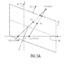
- Figure 3A shows a perspective projection. Shown is a 3D coordinate system with an x-axis 30, y-axis 31 and a z-axis 32.
- a 2D image is comprised of an array of discrete pixels arranged in rows and columns. Pixels in this context are the smallest entities considered by the image processing according to the invention. Each respective pixel of a specific row in the image can assume only a respective one of a series of discrete positions.
- Each row of pixels in an image runs parallel to the x-axis 30, so that individual pixels in a row are discriminated on the basis of their respective x-coordinates.
- Each column of pixels runs parallel to the y-axis 31 that points in a direction perpendicular to the x-axis 30.
- the depth of the scene is measured along the z-axis 32, which runs perpendicular to both the x-axis 30 and the y-axis 31.
- a respective z-value is assigned to each particular pixel in order to represent the depth of the scenery for that particular pixel.
- the 2D image observed from the observation point O 1 is formed by a projection of the 3D objects on the focus plane, which is also referred to as the projection plane.
- Figure 4A shows a scene observed from an observation point O 3 , corresponding to the input image, wherein a nearby object 40 is partially overlapping a further object 41. For clarity, the y-coordinates are not shown in the figure. Due to the overlapping, the input image comprises all pixels of the nearby object 40 and only some pixels of the further object 41, as illustrated by the observed image 42.
- Figure 4B shows the same scene observed from an observation point O 4 , which corresponds to the output image 43. As is clear from fig.4B the overlap has increased.
- the output image 43 of Figure 4B is derived from the input image 42 of Figure 4A, this increased overlap will be reflected by at least one input pixel corresponding to the background object 41 partly or totally being occluded by an input pixel corresponding to the foreground object 40. In the areas of overlap there are several candidates for the pixel values in the output image.
- the system according to the invention uses a reconstruction filter to determine for the output pixel locations (i.e. according to the grid of the output image) the input pixel(s) that after transformation contribute(s) to the output pixel location.
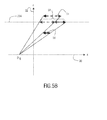
- Figure 5 shows an example wherein a 'hole' occurs in the output image 53 due to the fact that no input pixel is present to fill a position in the output image 53.
- Figure 5A shows that in the input image 52 a background object 51 is partly obscured by a foreground object 50.
- Figure 5B no overlap occurs between the objects 50 and 51 as can be observed from the output image 53, seen from an observation point O 6 .
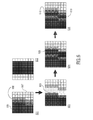
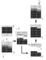
- the image processing system receives an input image 601 and a hidden image 602 at the input.
- the input image 601 is associated with the input viewpoint and shows, for example, a dark foreground object 606 and light background object 607. Due to pre-filtering of the camera that records the original video, the pixels at the depth boundary 608 comprise some color of both, the dark foreground and the light background object.
- the hidden image 602 is either associated with the input viewpoint or the output viewpoint. Transformation of the input image 601 to an output viewpoint may result in a de-occluded area 612 in the viewpoint transformed input image 603.
- This de-occluded area 612 is filled with pixels from the hidden image 602 and a filter is applied. It depends on the viewpoint the hidden image 602 is associated with, whether the hidden image 602 is to be transformed before the hidden image pixels can be used for filling the de-occluded area 612. Due to the pre-filtering some pixels which before transformation were located at the original depth boundary in the input image will still comprise some color of both the foreground and the background object. The transformation results in a new depth boundary in the output image 605. As a consequence the output image 605 comprises two different depth boundaries and a ghost line artifact 610 appears.
- FIG 8 illustrates detection of occlusions, using an x-coordinate extent 80.
- Occlusions are for example detected as follows.
- the video processor 106 is operative to sequentially process a scan line, i.e. a row with input pixels, in a direction opposite to a displacement from the input viewpoint ⁇ 0 81 to the output viewpoint ⁇ 1 82.
- the processing includes transforming input pixels to output pixels as a function of the associated input pixel depth.
- the projected pixels of pixels a 83, b 84 and c 85 are part of the input image associated with the viewpoint ⁇ 0 81. With the transformation to the output image 86 associated with the viewpoint ⁇ 1 82 pixel a 83 gets occluded.
- the pixels b 84 and c 85 are not occluded and are mapped onto the output image 86.
- the processing may include maintaining an x-coordinate extent 80 that indicates for already processed input pixels with respect to a predetermined start position a furthest x-coordinate already occluded by at least one transformed input pixel. Then, it can be concluded that if a pixel that is transformed does not lengthen the extent, it must be occluded by the previously processed pixels. In this event the pixel transformed from pixel a 83 does not lengthen the extent because it is occluded by the pixels transformed from pixel b 84. Therefore pixel a 83 is not included in the output image 86.
- the argument is analogous. In that event the scan line is traversed with increasing x-coordinate. Similarly, if a pixel that is transformed does lengthen the extent by more than a predetermined threshold, for example 1.5 pixels, part of the hidden image is de-occluded and at least one hidden image pixel is inserted in the output image 86.
- a predetermined threshold for example 1.5 pixels
- the base image layer In order to be able to efficiently fill in contributions from the hidden layer, it is preferred to interleave processing of the base image layer, and the hidden layer. For both scans, the extent in the output scan line may be maintained. In this way, only a single scan over the base image scan line is performed interleaved with a single scan over the hidden image scan line. Specifying the pixels of the hidden layer in the coordinate frame of the base image allows for easy integration of the transformed input image and the transformed hidden image.
- FIG. 9 shows the transformation of the input image shown in Figure 8, transformed to an output image associated with viewpoint ⁇ 2 ( ⁇ 2 > ⁇ l ).
- de-occlusions are detected using a look ahead extent 91.
- the x-coordinate extent 80 maintains the input pixels which, after transformation, are fed to a filter that prefilters and samples the output scan line at screen resolution.
- the look ahead extent 91 which is ahead of the x-coordinate extent 80 detects possible areas of occlusion, minification, magnification and/or de-occlusion.
- a pixel after transformation, does lengthen the look ahead extent 91 by more than a predetermined threshold, preferably 1.5 pixels, an area of de-occlusion is detected. For example after the viewpoint transformation from viewpoint ⁇ 0 to ⁇ 2 shown in Figure 9 a de-occluded area 92 occurs between the pixels b 84 and c 85. First the de-occlusion is detected by the look ahead extent 91. Later the x-coordinate extent 80 reaches the de-occluded area and the de-occluded pixel d 93 from the hidden layer 94 is inserted in the output image 86. In order to prevent ghost line artifacts preference to the hidden layer 94 is given for pixel positions adjacent to the de-occluded hidden image pixels.
- a predetermined threshold preferably 1.5 pixels
- one to four pixel positions before and/or after the de-occluded area are filled by pixels from the hidden image 94.
- color values of pixels are accumulated, which makes it extremely difficult to replace already processed pixels. Therefore the detection of the de-occluded area has to take place before the input samples to be replaced are fed to the filter.
- Using a look ahead extent 91 enables early detection of a de-occluded area.
- Figure 10 shows a schematic view of an embodiment 1000 of the image processing system according to the invention.
- the system uses four different extents.
- a base x-coordinate extent 1001 and a base look ahead extent 1002 are used for transforming the input pixels and detecting de-occluded areas in the transformed input image 1010, respectively.
- a hidden x-coordinate extent 1003 and a hidden look ahead extent 1004 simultaneously do the same for the hidden image 1012.
- Preferably extra hidden layers are available and an x-coordinate extent and a look ahead extent are provided for each hidden layer.
- the hidden look ahead extents may be used for determining if a hidden image pixel is available for inserting in or adjacent to a de-occluded area.
- the video processor 106 is operative to detect for each input pixel 1011 of the input image 1010 how much the pixel lengthens the base look ahead extent 1002 after transformation. If a pixel after transformation lengthens the look ahead extent by more than a predetermined threshold, for example 1.5 pixels, a de-occlusion is detected. Transformed pixels from the input image 1010 and the hidden image 1012 are fed to an input pixel selection unit 1005.
- the input pixel selection unit 1005 may be implemented as software or in hardware components in the video processor.
- the input pixel selection unit 1005 selects, based on information from the look ahead extents, which transformed pixels will be part of the output image.
- the selected pixels are fed to a video filter block 1006 before being displayed on a suitable display.
- a de-occluded area is detected by the look ahead extent 1002
- near the de-occluded area preference is given to the transformed pixels of the hidden image 1012 when the input pixel selection unit 1005 feeds pixels to the video filter block 1006.
- the pixel selection unit 1005 may be operative to determine if a hidden image pixel is available for inserting into the output image. If not, transformed input pixels known methods such as linear interpolation may be used for filling the de-occluded area and the adjacent pixel positions.
- Figure 11 shows a block diagram of a system in which the image processing system of the invention is advantageously used.
- the system shown in Figure 11 is an enhanced version of the conventional system shown in Figure 1.
- the memory 100 receives a hidden image 1101 and, optionally, hidden image pixel depth values. If a memory 103 is used for storing a copy 104 of the input image 101 and a copy 104 of the input depth 102, this memory further stores copies 1104 and 1105 of the hidden image pixels 1101 and the hidden image pixel depths 1102.
- the processor 1106 is operative to create output pixels of the output image.
- the output pixels are created as described above.
- the processor 1106 may be operative to transform the input image to an output image associated with a predetermined output viewpoint. In that event, the hidden image may not have to be transformed.
- the output viewpoint is chosen by an end user and both the input image pixels and the hidden image pixels are transformed to transformed pixels, associated with the output viewpoint.
Priority Applications (8)
| Application Number | Priority Date | Filing Date | Title |
|---|---|---|---|
| EP04101511A EP1587035A1 (fr) | 2004-04-14 | 2004-04-14 | Réduction des artefacts parasites pour rendre les graphics 2.5D |
| EP05718674A EP1738331B1 (fr) | 2004-04-14 | 2005-04-08 | Reduction des artefacts parasites pour rendre les graphics 2.5d |
| AT05718674T ATE484810T1 (de) | 2004-04-14 | 2005-04-08 | Geister-artefakt-reduktion zur wiedergabe von 2, 5d-graphik |
| CN2005800112561A CN1942902B (zh) | 2004-04-14 | 2005-04-08 | 用于2.5维图像再现的重影虚像的削减 |
| PCT/IB2005/051164 WO2005101324A1 (fr) | 2004-04-14 | 2005-04-08 | Reduction des artefacts fantomes pour le rendu de graphiques au format 2.5d |
| JP2007507898A JP4861309B2 (ja) | 2004-04-14 | 2005-04-08 | 2.5dグラフィックスをレンダリングするためのゴースト・アーチファクト削減 |
| DE602005024122T DE602005024122D1 (de) | 2004-04-14 | 2005-04-08 | Geister-artefakt-reduktion zur wiedergabe von 2,5d-graphik |
| US10/599,821 US7822265B2 (en) | 2004-04-14 | 2005-04-08 | Ghost artifact reduction for rendering 2.5D graphics |
Applications Claiming Priority (1)
| Application Number | Priority Date | Filing Date | Title |
|---|---|---|---|
| EP04101511A EP1587035A1 (fr) | 2004-04-14 | 2004-04-14 | Réduction des artefacts parasites pour rendre les graphics 2.5D |
Publications (1)
| Publication Number | Publication Date |
|---|---|
| EP1587035A1 true EP1587035A1 (fr) | 2005-10-19 |
Family
ID=34928951
Family Applications (2)
| Application Number | Title | Priority Date | Filing Date |
|---|---|---|---|
| EP04101511A Withdrawn EP1587035A1 (fr) | 2004-04-14 | 2004-04-14 | Réduction des artefacts parasites pour rendre les graphics 2.5D |
| EP05718674A Active EP1738331B1 (fr) | 2004-04-14 | 2005-04-08 | Reduction des artefacts parasites pour rendre les graphics 2.5d |
Family Applications After (1)
| Application Number | Title | Priority Date | Filing Date |
|---|---|---|---|
| EP05718674A Active EP1738331B1 (fr) | 2004-04-14 | 2005-04-08 | Reduction des artefacts parasites pour rendre les graphics 2.5d |
Country Status (7)
| Country | Link |
|---|---|
| US (1) | US7822265B2 (fr) |
| EP (2) | EP1587035A1 (fr) |
| JP (1) | JP4861309B2 (fr) |
| CN (1) | CN1942902B (fr) |
| AT (1) | ATE484810T1 (fr) |
| DE (1) | DE602005024122D1 (fr) |
| WO (1) | WO2005101324A1 (fr) |
Cited By (2)
| Publication number | Priority date | Publication date | Assignee | Title |
|---|---|---|---|---|
| CN102307312A (zh) * | 2011-08-31 | 2012-01-04 | 四川虹微技术有限公司 | 一种对dibr技术生成的目标图像进行空洞填充的方法 |
| CN103051908A (zh) * | 2012-12-26 | 2013-04-17 | 四川虹微技术有限公司 | 一种基于视差图的空洞填充装置 |
Families Citing this family (28)
| Publication number | Priority date | Publication date | Assignee | Title |
|---|---|---|---|---|
| EP1875440B1 (fr) * | 2005-04-19 | 2008-12-03 | Koninklijke Philips Electronics N.V. | Perception de la profondeur |
| US11315307B1 (en) | 2006-12-28 | 2022-04-26 | Tipping Point Medical Images, Llc | Method and apparatus for performing rotating viewpoints using a head display unit |
| US9349183B1 (en) * | 2006-12-28 | 2016-05-24 | David Byron Douglas | Method and apparatus for three dimensional viewing of images |
| US11228753B1 (en) | 2006-12-28 | 2022-01-18 | Robert Edwin Douglas | Method and apparatus for performing stereoscopic zooming on a head display unit |
| US10795457B2 (en) | 2006-12-28 | 2020-10-06 | D3D Technologies, Inc. | Interactive 3D cursor |
| US11275242B1 (en) | 2006-12-28 | 2022-03-15 | Tipping Point Medical Images, Llc | Method and apparatus for performing stereoscopic rotation of a volume on a head display unit |
| US8086025B2 (en) * | 2007-05-10 | 2011-12-27 | Monte Jerome Ramstad | Universal stereoscopic file format |
| US7889947B2 (en) | 2007-06-27 | 2011-02-15 | Microsoft Corporation | Image completion |
| US8508550B1 (en) * | 2008-06-10 | 2013-08-13 | Pixar | Selective rendering of objects |
| WO2009150529A1 (fr) * | 2008-06-13 | 2009-12-17 | Imax Corporation | Procédés et systèmes destinés à réduire ou à éliminer les images fantômes perçues sur les images stéréoscopiques affichées |
| JP5338166B2 (ja) | 2008-07-16 | 2013-11-13 | ソニー株式会社 | 送信装置、立体画像データ送信方法、受信装置および立体画像データ受信方法 |
| US8625881B2 (en) * | 2008-08-15 | 2014-01-07 | Reald Inc. | Enhanced ghost compensation for stereoscopic imagery |
| EP2180449A1 (fr) * | 2008-10-21 | 2010-04-28 | Koninklijke Philips Electronics N.V. | Procédé et dispositif pour la fourniture d'un modèle de profondeur stratifié |
| JP5469911B2 (ja) * | 2009-04-22 | 2014-04-16 | ソニー株式会社 | 送信装置および立体画像データの送信方法 |
| US9524700B2 (en) * | 2009-05-14 | 2016-12-20 | Pure Depth Limited | Method and system for displaying images of various formats on a single display |
| CN101908223A (zh) * | 2009-06-04 | 2010-12-08 | 曹立宏 | 2.5d虚拟人物的动作表情展现技术 |
| CN102104584B (zh) * | 2009-12-21 | 2013-09-04 | 中国移动通信集团公司 | 下发3d模型数据的方法、装置和3d模型数据传输系统 |
| CN101833781B (zh) * | 2010-04-22 | 2012-09-05 | 清华大学 | 基于几何信息的相似对象隐藏部分自动补全方法 |
| JP5627498B2 (ja) * | 2010-07-08 | 2014-11-19 | 株式会社東芝 | 立体画像生成装置及び方法 |
| US9865083B2 (en) * | 2010-11-03 | 2018-01-09 | Industrial Technology Research Institute | Apparatus and method for inpainting three-dimensional stereoscopic image |
| JP5050094B2 (ja) * | 2010-12-21 | 2012-10-17 | 株式会社東芝 | 映像処理装置及び映像処理方法 |
| US20120299805A1 (en) * | 2011-05-26 | 2012-11-29 | Sanyo Electric., Ltd. | Projection display apparatus |
| EP2734976B1 (fr) | 2011-07-21 | 2019-02-20 | Imax Corporation | Normalisation généralisée pour un dispositif d'affichage d'image |
| US20160253839A1 (en) | 2015-03-01 | 2016-09-01 | Nextvr Inc. | Methods and apparatus for making environmental measurements and/or using such measurements in 3d image rendering |
| CN105844264B (zh) * | 2015-05-19 | 2019-03-22 | 北京林业大学 | 一种基于受力的油用牡丹果实图像的识别方法 |
| US11054108B2 (en) | 2017-01-17 | 2021-07-06 | Signify Holding B.V. | Adjustable spot light position generation |
| CN108537873B (zh) * | 2018-04-13 | 2022-07-26 | 广州悦世界信息科技有限公司 | 生成2d游戏斜45度地图不规则墙体的方法 |
| US11094108B2 (en) | 2018-09-27 | 2021-08-17 | Snap Inc. | Three dimensional scene inpainting using stereo extraction |
Citations (3)
| Publication number | Priority date | Publication date | Assignee | Title |
|---|---|---|---|---|
| US4925294A (en) * | 1986-12-17 | 1990-05-15 | Geshwind David M | Method to convert two dimensional motion pictures for three-dimensional systems |
| WO2000030039A1 (fr) * | 1998-11-19 | 2000-05-25 | Push Entertainment Inc. | Systeme et procede permettant de creer des modeles 3d a partir de donnees d"images sequentielles 2d |
| US6417850B1 (en) * | 1999-01-27 | 2002-07-09 | Compaq Information Technologies Group, L.P. | Depth painting for 3-D rendering applications |
Family Cites Families (7)
| Publication number | Priority date | Publication date | Assignee | Title |
|---|---|---|---|---|
| CA1332192C (fr) * | 1983-05-09 | 1994-09-27 | David M. Geshwind | Methode de colorisation d'images |
| JPH08115439A (ja) * | 1994-10-13 | 1996-05-07 | Canon Inc | 画像データ処理装置及び画像再生装置 |
| JP3826236B2 (ja) * | 1995-05-08 | 2006-09-27 | 松下電器産業株式会社 | 中間像生成方法、中間像生成装置、視差推定方法、及び画像伝送表示装置 |
| US5963664A (en) * | 1995-06-22 | 1999-10-05 | Sarnoff Corporation | Method and system for image combination using a parallax-based technique |
| JP4392060B2 (ja) * | 1995-12-19 | 2009-12-24 | コーニンクレッカ フィリップス エレクトロニクス エヌ ヴィ | 視差深度依存画素シフト |
| GB9611939D0 (en) * | 1996-06-07 | 1996-08-07 | Philips Electronics Nv | Stereoscopic image display driver apparatus |
| EP1353518A1 (fr) * | 2002-04-09 | 2003-10-15 | STMicroelectronics S.r.l. | Procédé et système pour la génération des images stéréoscopiques à partir d'images monoculaires |
-
2004
- 2004-04-14 EP EP04101511A patent/EP1587035A1/fr not_active Withdrawn
-
2005
- 2005-04-08 JP JP2007507898A patent/JP4861309B2/ja active Active
- 2005-04-08 AT AT05718674T patent/ATE484810T1/de not_active IP Right Cessation
- 2005-04-08 EP EP05718674A patent/EP1738331B1/fr active Active
- 2005-04-08 CN CN2005800112561A patent/CN1942902B/zh active Active
- 2005-04-08 US US10/599,821 patent/US7822265B2/en active Active
- 2005-04-08 DE DE602005024122T patent/DE602005024122D1/de active Active
- 2005-04-08 WO PCT/IB2005/051164 patent/WO2005101324A1/fr not_active Application Discontinuation
Patent Citations (3)
| Publication number | Priority date | Publication date | Assignee | Title |
|---|---|---|---|---|
| US4925294A (en) * | 1986-12-17 | 1990-05-15 | Geshwind David M | Method to convert two dimensional motion pictures for three-dimensional systems |
| WO2000030039A1 (fr) * | 1998-11-19 | 2000-05-25 | Push Entertainment Inc. | Systeme et procede permettant de creer des modeles 3d a partir de donnees d"images sequentielles 2d |
| US6417850B1 (en) * | 1999-01-27 | 2002-07-09 | Compaq Information Technologies Group, L.P. | Depth painting for 3-D rendering applications |
Non-Patent Citations (1)
| Title |
|---|
| CURTI S., SIRTORI D., VELLA F.: "3D Effect Generation from Monocular View", PROCEEDINGS OF THE FIRST INTERNATIONAL SYMPOSIUM ON 3D DATA PROCESSING VISUALIZATION AND TRANSMISSION, 19 June 2002 (2002-06-19), pages 550 - 553, XP002297656 * |
Cited By (4)
| Publication number | Priority date | Publication date | Assignee | Title |
|---|---|---|---|---|
| CN102307312A (zh) * | 2011-08-31 | 2012-01-04 | 四川虹微技术有限公司 | 一种对dibr技术生成的目标图像进行空洞填充的方法 |
| CN102307312B (zh) * | 2011-08-31 | 2013-06-05 | 四川虹微技术有限公司 | 一种对dibr技术生成的目标图像进行空洞填充的方法 |
| CN103051908A (zh) * | 2012-12-26 | 2013-04-17 | 四川虹微技术有限公司 | 一种基于视差图的空洞填充装置 |
| CN103051908B (zh) * | 2012-12-26 | 2014-11-05 | 四川虹微技术有限公司 | 一种基于视差图的空洞填充装置 |
Also Published As
| Publication number | Publication date |
|---|---|
| CN1942902B (zh) | 2010-05-12 |
| DE602005024122D1 (de) | 2010-11-25 |
| EP1738331A1 (fr) | 2007-01-03 |
| JP4861309B2 (ja) | 2012-01-25 |
| WO2005101324A1 (fr) | 2005-10-27 |
| ATE484810T1 (de) | 2010-10-15 |
| US7822265B2 (en) | 2010-10-26 |
| CN1942902A (zh) | 2007-04-04 |
| US20080267527A1 (en) | 2008-10-30 |
| JP2007533022A (ja) | 2007-11-15 |
| EP1738331B1 (fr) | 2010-10-13 |
Similar Documents
| Publication | Publication Date | Title |
|---|---|---|
| US7822265B2 (en) | Ghost artifact reduction for rendering 2.5D graphics | |
| US7689031B2 (en) | Video filtering for stereo images | |
| JP4740135B2 (ja) | 3次元画像ディスプレイの画面に3次元画像を描画するシステム及び方法 | |
| JP5011316B2 (ja) | 出力画像のレンダリング | |
| EP0809913B1 (fr) | Decalages parallactiques de pixels dependant de la profondeur | |
| JP4764305B2 (ja) | 立体画像生成装置、方法およびプログラム | |
| EP1897056B1 (fr) | Échange combiné de données d'image et de données apparentées | |
| US8633967B2 (en) | Method and device for the creation of pseudo-holographic images | |
| JP4328311B2 (ja) | 三次元画像表示用多視点画像の作成方法およびプログラム | |
| JP6060329B2 (ja) | 3dディスプレイ装置で3次元映像を視覚化する方法および3dディスプレイ装置 | |
| JP4471979B2 (ja) | 画像合成装置及び画像合成方法 | |
| US8797383B2 (en) | Method for stereoscopic illustration | |
| KR100239132B1 (ko) | 3차원 시차 그리기 장치 및 방법 | |
| KR20240026222A (ko) | 이미지 생성 | |
| Brettle et al. | Stereo Rendering: An Overview |
Legal Events
| Date | Code | Title | Description |
|---|---|---|---|
| PUAI | Public reference made under article 153(3) epc to a published international application that has entered the european phase |
Free format text: ORIGINAL CODE: 0009012 |
|
| AK | Designated contracting states |
Kind code of ref document: A1 Designated state(s): AT BE BG CH CY CZ DE DK EE ES FI FR GB GR HU IE IT LI LU MC NL PL PT RO SE SI SK TR |
|
| AX | Request for extension of the european patent |
Extension state: AL HR LT LV MK |
|
| STAA | Information on the status of an ep patent application or granted ep patent |
Free format text: STATUS: THE APPLICATION IS DEEMED TO BE WITHDRAWN |
|
| 17P | Request for examination filed |
Effective date: 20060419 |
|
| 18D | Application deemed to be withdrawn |
Effective date: 20051201 |