EP1586864A2 - Rotation angle detecting apparatus and electric power steering apparatus - Google Patents
Rotation angle detecting apparatus and electric power steering apparatus Download PDFInfo
- Publication number
- EP1586864A2 EP1586864A2 EP05008169A EP05008169A EP1586864A2 EP 1586864 A2 EP1586864 A2 EP 1586864A2 EP 05008169 A EP05008169 A EP 05008169A EP 05008169 A EP05008169 A EP 05008169A EP 1586864 A2 EP1586864 A2 EP 1586864A2
- Authority
- EP
- European Patent Office
- Prior art keywords
- resistance
- output
- angular resolver
- ground fault
- resolver
- Prior art date
- Legal status (The legal status is an assumption and is not a legal conclusion. Google has not performed a legal analysis and makes no representation as to the accuracy of the status listed.)
- Granted
Links
Images





Classifications
-
- G—PHYSICS
- G01—MEASURING; TESTING
- G01D—MEASURING NOT SPECIALLY ADAPTED FOR A SPECIFIC VARIABLE; ARRANGEMENTS FOR MEASURING TWO OR MORE VARIABLES NOT COVERED IN A SINGLE OTHER SUBCLASS; TARIFF METERING APPARATUS; MEASURING OR TESTING NOT OTHERWISE PROVIDED FOR
- G01D5/00—Mechanical means for transferring the output of a sensing member; Means for converting the output of a sensing member to another variable where the form or nature of the sensing member does not constrain the means for converting; Transducers not specially adapted for a specific variable
- G01D5/12—Mechanical means for transferring the output of a sensing member; Means for converting the output of a sensing member to another variable where the form or nature of the sensing member does not constrain the means for converting; Transducers not specially adapted for a specific variable using electric or magnetic means
- G01D5/244—Mechanical means for transferring the output of a sensing member; Means for converting the output of a sensing member to another variable where the form or nature of the sensing member does not constrain the means for converting; Transducers not specially adapted for a specific variable using electric or magnetic means influencing characteristics of pulses or pulse trains; generating pulses or pulse trains
- G01D5/24457—Failure detection
- G01D5/24466—Comparison of the error value to a threshold
-
- G—PHYSICS
- G01—MEASURING; TESTING
- G01D—MEASURING NOT SPECIALLY ADAPTED FOR A SPECIFIC VARIABLE; ARRANGEMENTS FOR MEASURING TWO OR MORE VARIABLES NOT COVERED IN A SINGLE OTHER SUBCLASS; TARIFF METERING APPARATUS; MEASURING OR TESTING NOT OTHERWISE PROVIDED FOR
- G01D5/00—Mechanical means for transferring the output of a sensing member; Means for converting the output of a sensing member to another variable where the form or nature of the sensing member does not constrain the means for converting; Transducers not specially adapted for a specific variable
- G01D5/12—Mechanical means for transferring the output of a sensing member; Means for converting the output of a sensing member to another variable where the form or nature of the sensing member does not constrain the means for converting; Transducers not specially adapted for a specific variable using electric or magnetic means
- G01D5/244—Mechanical means for transferring the output of a sensing member; Means for converting the output of a sensing member to another variable where the form or nature of the sensing member does not constrain the means for converting; Transducers not specially adapted for a specific variable using electric or magnetic means influencing characteristics of pulses or pulse trains; generating pulses or pulse trains
- G01D5/24457—Failure detection
-
- H—ELECTRICITY
- H02—GENERATION; CONVERSION OR DISTRIBUTION OF ELECTRIC POWER
- H02H—EMERGENCY PROTECTIVE CIRCUIT ARRANGEMENTS
- H02H3/00—Emergency protective circuit arrangements for automatic disconnection directly responsive to an undesired change from normal electric working condition with or without subsequent reconnection ; integrated protection
- H02H3/16—Emergency protective circuit arrangements for automatic disconnection directly responsive to an undesired change from normal electric working condition with or without subsequent reconnection ; integrated protection responsive to fault current to earth, frame or mass
Definitions
- the present invention relates to a rotating angle detecting apparatus detecting a rotating angle of a detected subject by using an angular resolver, and an electric power steering apparatus assisting a steering by attaching the angular resolver to a torsion bar connected to a steering wheel, detecting a steering torque on the basis of a rotating angle determined by the angular resolver, and determining an assist amount so as to control a motor.
- an output from the angular resolver is constituted by alternating-current analogue signals of a sin phase or a cos phase
- the output is generally raised by applying an offset voltage to the sin phase and the cos phase in accordance with an offset voltage applying circuit so as to convert into a direct-current analogue signal and thereafter is converted into a digital signal via an A/D converter, for the purpose of allowing a process by a CPU.
- JP 2000-132226 A shows a structure for detecting a disconnection of the resolver.
- JP HEI 11-37797 A shows a structure for detecting a disconnection of the sensor and a ground fault.
- the electric power steering apparatus in order to increase a reliability it is desirable to detect the disconnection and the ground fault between the angular resolver detecting the steering torque and the CPU and employ a countermeasure of gradually lowering the assist force or the like when the disconnection or the ground fault is occurred. For example, when a harness comes off due to a vibration or the like and the disconnection is generated, or when a wire is in contact with a vehicle body in the case that the vehicle runs on a curb stone and the ground fault is generated, it is necessary to stop the assist of the steering on the basis of a signal from the angular resolver.
- the direct-current component resistance value of the output coil structuring the angular resolver is small and the change amount of the potential is small even when the direct-current component resistance value becomes zero, so that the change amount of the voltage is not distinguished from a variation of the signal potential at a normal time on the basis of the angular resolver itself, a variation of a characteristic of an electronic circuit and a temperature change.
- the ground fault can not be actually detected.
- the present invention is made for the purpose of solving the problem mentioned above, and an object of the present invention is to provide a rotating angle detecting apparatus which can detect a ground fault of an angular resolver without error, and an electric power steering apparatus.
- a rotating angle detecting apparatus comprising:
- an electric power steering apparatus comprising:
- the values of the first resistance R1, the second resistance R2, the third resistance R3 and the fourth resistance R4 are set such that an output of the differential amplifier becomes equal to or more than the predetermined margin for preventing the erroneous ground fault detection in the computing unit, in the difference between the minimum output potential at a time when the angular resolver is not in the ground fault which can be generated by the variation of the values of the first resistance R1, the second resistance R2, the third resistance R3 and the fourth resistance R4 and the dirert-current resistance component of the angular resolver output coil, and the maximum potential at a time when the angular resolver is in the ground fault.
- the magnification K of the third resistance R3 with respect to the direct-current resistance component of the angular resolver output coil is first determined such that the difference between the minimum output potential Vout Min at a time when the angular resolver is not in the ground fault, and the maximum potential Vout Max at a time when the angular resolver is in the ground fault becomes equal to or more than the predetermined margin.
- the gain Gain of the differential amplifier defined such that the difference between the minimum output potential and the maximum potential becomes equal to or more than the predetermined margin is defined in the predetermined range on the basis of the value of the third resistance R3 determined by the magnification K.
- the values of the first resistance R1, the second resistance R2 and the fourth resistance R4 are set on the basis of the gain Gain. Since the magnification K of the third resistance R3 with respect to the direct-current resistance component Rdc of the angular resolver output coil is first defined to the low level, four example, quadruple or less, the output of the differential amplifier is relatively largely changed in comparison with the time when the angular resolver is not in the ground fault, in the case that the direct-current component resistance Rdc of the angular resolver becomes zero due to the ground fault.
- the values of the first resistance R1, the second resistance R2, the third resistance R3 and the fourth resistance R4 are set such that an output of the differential amplifier becomes equal to or more than the predetermined margin for preventing the erroneous ground fault detection in the computing unit, in the difference between the minimum output potential at a time when the angular resolver is not in the ground fault which can be generated by the variation of the values of the first resistance R1, the second resistance R2, the third resistance R3 and the fourth resistance R4 and the direct-current resistance component of the angular resolver output coil, and the maximum potential at a time when the angular resolver is in the ground fault.
- the electric power steering apparatus 20 is mainly constituted by a steering wheel 21, a steering shaft 22, a pinion shaft 23, a rack shaft 24, a torque sensor 30, a motor 40, a motor resolver 44, a ball screw mechanism 50, an ECU 60 and the like, detects a steering state of the steering wheel 21, and generates an assist force in correspondance to the steering state by the motor 40 so as to assist a steering operation by a driver.
- tire wheels (not shown) are connected to both ends of the rack shaft 24 respectively via tie rods or the like.
- one end side of the steering shaft 22 is connected to the steering wheel 21, and an input shaft 23a of the pinion shaft 23 received within a pinion housing 25 and a torsion bar (an elastic member) 31 are connected to the other end side of the steering shaft 22 by a pin 32. Further, an output shaft 23b of the pinion shaft 23 is connected to the other end side 31a of the torsion bar 31.
- the input shaft 23a of the pinion shaft 23 and the output shaft 23b are axially supported by a bearing 33a and a bearing 33b respectively so as to be rotatable within the pinion housing 25, a first angular resolver 35 is provided between the input shaft 23a and the pinion housing 25, and a second angular resolver 37 is provided between the output shaft 23b and the pinion housing 25, respectively.
- the first angular resolver 35 and the second angular resolver 37 can detect a steering angle by the steering wheel 21, and are electrically connected to the ECU 60 via a terminal 39 respectively (refer to Fig. 4).
- a pinion gear 23c is formed in an end portion of the output shaft 23b of the pinion shaft 23, and a rack groove 24a of the rack shaft 24 is meshed with the pinion gear 23c. Accordingly, a rack and pinion mechanism is structured.
- the steering shaft 22 and the pinion shaft 23 by the torsion bar 31 so as to be relatively rotatable, and it is possible to detect a rotating angle of the steering shaft 22, that is, a rotating angle (a mechanical angle) ⁇ m of the steering wheel 21 on the basis of a first steering angle (an electrical angle) ⁇ e1 by the first angular resolver 35 and a second steering angle (an electric angle) ⁇ e2 by the second angular resolver 37. Further, It is possible to detect a torsion amount (corresponding to the steering torque) of the torsion bar 31 as a torsion angle on the basis of an angular difference between the first steering angle ⁇ e1 and the second steering angle ⁇ e2.
- the rack shaft 24 is received within a rack housing 26 and a motor housing 27, and a ball screw groove 24b is spirally formed in an intermediate portion thereof.
- a cylindrical motor shaft 43 which is axially supported by a bearing 29 so as to be coaxially rotatable with the rack shaft 24.
- the motor shaft 43 structures the motor 40 together with a stator 41, an exciting coil 42 and the like, and is structured such that a magnetic field generated by the exciting coil 42 wound around the stator 41 acts on a permanent magnet 45 provided in an outer periphery of the motor shaft 43 corresponding to a rotor, whereby the motor shaft 43 can rotate.
- a ball screw nut 52 is attached to an inner periphery of the motor shaft 43 , and a ball screw groove 52a is also formed spirally in the ball screw nut 52. Accordingly, a ball screw mechanism 50 capable of moving the rack shaft 24 in an axial direction on the basis of a rotation of the motor shaft 43 can be structured by interposing a lot of balls 54 between the ball screw groove 52a of the ball screw nut 52 and the ball screw groove 24b of the rack shaft 24.
- the motor resolver 44 which can detect a rotating angle (an electric angle) ⁇ Me of the motor shaft 43 is provided between the motor shaft 43 of the motor 40 and the motor housing 27, and the motor resolver 44 is electrically connected to the ECU 60 via a terminal (not shown) (refer to Fig. 4).
- Fig. 4 shows a control structure of an electric power steering apparatus 20 in accordance with a first embodiment.
- the ECU 60 gives an exciting signal to the first angular resolver 35, the second angular resolver 37 and the motor resolver 44 from output ports 60a, 60b and 60c.
- a sin phase output from a sin output terminal 35s of the first angular resolver 35, a cos phase output from a cos output terminal 35c, a sin phase output from a sin output terminal 37s of the second angular resolver 37, and a cos phase output from a cos output terminal 37c are input to the ECU 60 of the electric power steering apparatus 20.
- a direct-current offset voltage is applied to each of the sin phase outputs and the cos phase outputs via a buffer 64 of the ECU 60, and each of the sin phase outputs and the cos phase outputs is input to an A/D converter side of the CPU 62, and is A/D converted.
- the CPU 62 detects rotating angles of the first angular resolver 35 and the second angular resolver 37 from the A/D converted sin phase outputs and cos phase outputs so as to compute a steering torque T, and outputs an assist commands for assisting the steering force in correspondence to the steering torque T to a motor drive circuit 70 side.
- the motor drive circuit 70 generates a torque in correspondence to the assist command in the motor 40.
- the rotating angle of the motor 40 is detected by the motor resolver 44, and a sin phase output from a sin output terminal 44s and a cos phase output from a cos output terminal 44c are fed back to the motor drive circuit 70, and are also output to the ECU 60.
- the ECU 60 computes respective steering angles on the basis of the outputs from the first angular resolver 35, the second angular resolver 37 and the motor resolver 44, the assist amount of the steering force mentioned above in correspondence to the steering angle, and detects a ground fault of the angular resolvers.
- the first angular resolver 35 is an angular resolver structured by a first yoke YK1, a second yoke YK2, a third yoke YK3, a fourth yoke YK4, a first coil CL1, a second coil CL2, a third coil CL3 and a fourth coil CL4.
- the first yoke YK1 is formed in an annular shape along an inner periphery of the pinion housing 25, and is fixed to the pinion housing 25. Further, the first coil CL1 is wound around an inner periphery of the first yoke YK1.
- the second yoke YK2 is formed in an annular shape in the same manner as that of the first yoke YK1, is fixed to an outer periphery of the input shaft 23a of the pinion shaft 23 so as to oppose to the first yoke YK1, and the second coil CL2 is wound around the second yoke YK2. Accordingly, the second yoke YK2 can integrally rotate with the input shaft 23a.
- the third yoke YK3 is fixed on an outer periphery of the input shaft 23a so as to be shifted in an axial direction of the input shaft 23a from the second yoke YK2, and is structured such as to be integrally rotatable with the input shaft 23a.
- the third coil CL3 is wound around the third yoke YK3, and the third coil CL3 is electrically connected to the second coil CL2 of the second yoke YK2 in serial.
- the fourth yoke YK4 is formed in an annular shape along the inner periphery of the housing 25 in the same manner as that of the first yoke YK1, and is fixed to the pinion housing 25.
- the fourth coil CL4 is constituted by two kinds of coils in which phases are shifted at 90 degrees.
- the second angular resolver 37 is structured in the same manner as the first angular resolver 35 except a point that the second yoke YK2, the third yoke YK3, the second coil CL2 and the third coil CL3 are provided in the output shaft 23b as is different from the first angular resolver 35.
- the motor resolver 44 is structured in the same manner as the first angular resolver 35 except a point that the first yoke YK1, the fourth yoke YK4, the first coil CL1 and the fourth coil CL4 are provided in the motor housing 27, and a point that the second yoke YK2, the third yoke YK3, the second coil CL2 and the third coil CL3 are provided in the motor shaft 43 as is different from the first angular resolver 35.
- the first angular resolver 35 is constituted by the first coil CL1 to the fourth coil CL4 as mentioned above, and is a so-called one-phase exciting and two-phase output (voltage detecting) type angular resolver having a connection relation of the coils as shown in the circuit diagram of Fig. 5B. Accordingly, it is possible to obtain angular resolver output signals E2 (a sin phase output in Fig. 4) and E3 (a cos phase output in Fig.
- the direct-current offset voltage is applied via the buffer 64 of the ECU 60 as shown in Fig. 4, is thereafter input to the A/D converter side of the CPU 62 and is A/D converted, thereby being converted into a digital signal which can be processed by the CPU 62.
- the buffer 64 applies the direct-current offset voltage to the sin phase signal and the cos phase signal with reference to Fig. 6 A and 6 B.
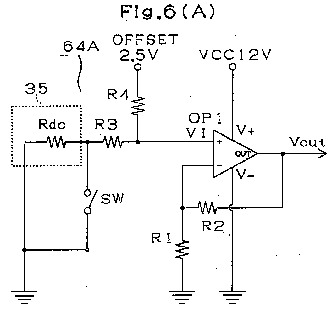
- the buffer 64 is constituted by a direct-current offset voltage applying circuit 64A applying a direct-current offset voltage to the sin phase signal of the first angular resolver 35 shown in Fig. 6A, and an offset voltage generating circuit 64B generating an offset voltage (2.5 V) for the direct-current offset voltage applying circuit 64A shown in Fig. 6B.
- the direct-current offset voltage applying circuit 64A is constituted by a first differential amplifier OP1, a first resistance R1 connected between an inverting input of the first differential amplifier OP1 and a ground earth (a reference potential), a second resistance R2 for a negative feedback connected between an output and the inverting input of the first differential amplifier OP1, a third resistance R3 connected in series between the angular resolver 35 connected to the ground earth (the reference potential) and a non-inverting input of the first differential amplifier OP1, and a fourth resistance R4 connected between an offset potential and the non-inverting input.
- a direct-current resistance component of the output coil in the angular resolver 35 is shown by reference symbol Rdc.
- the offset voltage generating circuit 64B is constituted by a second differential amplifier OP2, and a fifth resistance R5 and a sixth resistance R6 which divide a voltage of a power source Vcc (5 V).
- the sixth resistance R6 is connected to the ground earth, a potential divided by the fifth resistance R5 and the sixth resistance R6 is connected to a non-inverting input of the second differential amplifier OP2, and an output of the second differential amplifier OP2 is connected to an inverting input so as to be negative fed back.
- 2.5 V (the offset voltage) correspondind to a half of the power source Vcc (5V) is output from the second differential amplifier OP2 by making values of the fifth resistance R5 and the sixth resistance R6 equal to each other.
- a DC voltage calculating expression of the output Vout of the direct-current offset voltage applying circuit 64A is shown below.
- Vout Vi ⁇ (R2 + R1)/R1
- Vout ⁇ OFFSET ⁇ (Rdc + R3)/(Rdc + R3 + R4) ⁇ ⁇ (R2 + R1)/R1
- Vout ⁇ 5.0 ⁇ R6/(R5 + R6) ⁇ (Rdc + R3)/(Rdc + R3 + R4) ⁇ (R2 + R1)/R1
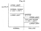
- a predetermined margin for example 0.11 V
- 0.11 V in all the temperaure (-40 to 125 degree), and it is possible to separate the normal and the ground fault.
- a breakdown of 0.11 V is obtained by adding an error 0.01 V at a time of the A/D conversion to a noise 0.10 V generated in the motor vehicle.
- Vout Max The upper limit (Vout Max) and the lower limit (Vout Min) of the output Vout is determined by the following expression.
- Vout ⁇ 5.0 ⁇ (1 + R5/R6) -1 ⁇ (1 + R4/(R3 + Rdc)) -1 ⁇ ⁇ (1 + R2/R1)
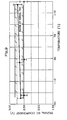
- each of the lower limit (Vout min) of the output Vout at the normal time and upper limit (Vout max) of the output Vout at the ground fault time is expressed by two variables, i.e. the magnification K and Gain, with considering the upper limit value and the lower limit value of each of the constituting members.
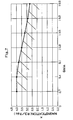
- Fig. 7 shown in Fig. 7 is the relation between the magnification K and Gain which is capable of securing the predetermined margin (for example, 0.11 V) between the voltage range (the lower limit) of the output Vout at the normal time and the voltage range (the upper limit) of the output Vout at the ground fault time.
- Gain is 2.7
- the resistance value of the third resistance R3 is set to be equal to or less than 120 ⁇ , it is possible to secure the predetermined margin (0.11 V), and it is possible to detect the ground fault.
- the magnification K it is preferable to set the larger value within the range capable of detecting the ground fault because an amount of the offset current flowing to the ground earth side via the angular resolver becomes small and the offset voltage generating circuit 64B can be made small.
- the sin phase signal and the cos phase signal from each of the resolvers 35, 37 and 44 are input via the buffer 64 (S12), and it is determined from the output Vout whether or not the ground fault is generated (S14) .
- the step executes the normal control, that is, the assist of the steering in correspondence to the detected rotating angle (S18).
- the motor 40 is controlled by computing the torsion angle of the torsion bar 31 on the basis of the difference betwem the rotating angle detected by the first angular resolver 35 and the rotating angle detected by the second angular resolver 37 and determining the assist amount on the basis of the computed torsion angle.
- the step executes the control at the ground fault time, that is, the assist of the steering in to the most recent rotating angle in the past data stored as the normal value, and reduces the assist amount gradually to zero (S16).
- the magnification K of the third resistance R3 with respect to the direct-current resistance component Rdc of the resolver output coil is determined in such a manner that the difference between the minimum output potential Vout Min at a time when the angular resolver is not in the ground fault and the maximum potential Vout Max at a time when the angular resolver is in the ground fault becomes equal to or more than the predetermined margin. Further, the gain Gain of the differential amplifier determined such that the difference between the minimum output potential and the maximum potential becomes equal to or more than the predetermined margin is within the predetermined range, on the basis of the value of the third resistance R3 determined by the magnification K.
- the values of the first resistance R1, the second resistance R2 and the fourth resistance R4 are set on the basis of the gain Gain.
- it is possible to stably operate the differential amplifier by setting the relation R4/R3 R1/R2.
- the output of the differential amplifier is relatively largely changed with respect to the time when the angular resolver is not in the ground fault at a time when the direct-current resistance Rdc of the angular resolver becomes zero due to the ground fault, by defining the magnification K of the third resistance R3 with respect to the direct resistance component Rdc of the resolver output coil to the low level, for example, quadruple or less. Accordingly, it is possible to set the difference between the minimum output potential Vout Min at a time when the angular resolver is not in the ground fault and the maximum potential at the ground fault time of the angular resolver to the predetermined margin or more.
- the values of the first resistance R1, the second resistance R2, the third resistance R3 and the fourth resistance R4 are set such that the difference between the minimum output potential Vout Min of the first differential amplifier OP1 at a time when the angular resolver is not in the ground fault time of the angular resolver which may be generated on the basis of the dispersion of the values of the first resistance R1, the second resistance R2, the third resistance R3 and the fourth resistance R4, and the direct current resistance component Rdc of the resolver output coil, and the maximum potential Vout Max of the first differential amplifier OP1 at the ground fault time of the angular resolver becomes equal to or more than the predetermined margin (for example, 0.11 V) for preventing the erroneous ground fault detection in the CPU 62 side.
- the predetermined margin for example, 0.11 V
- the embodiment mentioned above is exemplified by the rotating angle of the steering shaft of the electric power steering apparatus, the torsion angle of the torsion bar, and the ground fault detection of the angular resolver used for detecting the rotation of the motor.
- the structure of the present invention can be applied to a rotating angle detecting apparatus using various angular resolvers.
- the output of the buffer 64 is A/D converted, however, the ground fault detection can be executed by comparing with a threshold value using a comparator in place of the A/D conversion.
- the invention provides an electric power steering apparatus which can detect a ground fault of an angular resolver without fault.
- Values of a first resistance (R1), a second resistance (R2), a third resistance (R3) and a fourth resistance (R4) are set such that a difference between a minimum output potential (Vout Min) of a first differential amplifier (OP1) at a time when an angular resolve is not in a ground fault which may be generated on the basis of a dispersion of the first resistance (R1), the second resistance (R2), the third resistance (R3) and the fourth resistance (R4), and a direct-current resistance component (Rdc) of the angular resolver, and a maximum potential (Vout Max) at a time when the angular resolver is in the ground fault becomes equal to or more than a predetermined margin for preventing an erroneous ground fault detection in a CPU (62) side. Accordingly, it is possible to detect the ground fault of the angular resolver on the basis of an output potential (Vout) of the first differential amplifier (OP1) without fault.
Landscapes
- Physics & Mathematics (AREA)
- General Physics & Mathematics (AREA)
- Transmission And Conversion Of Sensor Element Output (AREA)
- Power Steering Mechanism (AREA)
- Measurement Of Length, Angles, Or The Like Using Electric Or Magnetic Means (AREA)
Abstract
Description
wherein values of the first resistance R1, the second resistance R2, the third resistance R3 and the fourth resistance R4 are set such that an output Vout of the differential amplifier OP1 becomes equal to or more than a predetermined margin for preventing an erroneous ground fault detection in the computing unit, in a difference between a minimum output potential Vout Min at a time when the angular resolver is not in a ground fault generated by a variation of the values of the first resistance R1, the second resistance R2, the third resistance R3 and the fourth resistance R4 and the direct-current resistance component of the angular resolver output coil, and a maximum potential Vout Max at a time when the angular resolver 35 is in the ground fault.
wherein values of the first resistance R1, the second resistance R2, the third resistance R3 and the fourth resistance R4 are set such that an output of the differential amplifier OP1 becomes equal to or more than a predetermined margin for preventing an erroneous ground fault detection in the computing unit, in a difference between a minimum output potential Vout Min at a time when the angular resolver is not in a ground fault generated by a variation of the values of the first resistance R1, the second resistance R2, the third resistance R3 and the fourth resistance R4 and the direct-current resistance oomponent of the angular resolver output coil, and a maximum potential Vout Max at a time when the angular resolver 35 is in the ground fault.
First, a descritption will be given of a main structure of an electric power steering apparatus 20 in accordance with the present embodiment with reference to Figs. 1 to 4. As shown in Figs. 1 to 4, the electric power steering apparatus 20 is mainly constituted by a steering wheel 21, a steering shaft 22, a pinion shaft 23, a rack shaft 24, a torque sensor 30, a motor 40, a motor resolver 44, a ball screw mechanism 50, an ECU 60 and the like, detects a steering state of the steering wheel 21, and generates an assist force in correspondance to the steering state by the motor 40 so as to assist a steering operation by a driver. In this case, tire wheels (not shown) are connected to both ends of the rack shaft 24 respectively via tie rods or the like.
The buffer 64 is constituted by a direct-current offset voltage applying circuit 64A applying a direct-current offset voltage to the sin phase signal of the first angular resolver 35 shown in Fig. 6A, and an offset voltage generating circuit 64B generating an offset voltage (2.5 V) for the direct-current offset voltage applying circuit 64A shown in Fig. 6B.
In this case, an applied voltage Vi to the non-inverting input of the first differential amplifier OP1 can be expressed by the following expression.
In this case, allowing the ground fault to be detected means that the voltage range (from the upper limit to the lower limit) of the output Vout at the normal time (Rdc ≠ 0) and the voltage range (from the upper limit to the lower limit) of the output Vout at the ground fault time (Rdc= 0), that is, the voltage range (the lower limit) of the output Vout at the normal time and the voltage range (the upper limit) of the output Vout at the ground fault time do not overlap while securing a predetermined margin (for example, 0.11 V), as shown in Fig. 10. In other words, it means that even if the constituting parts having the worst characteristics are combined, it is possible to secure the predetermined margin (for example. 0.11 V) in all the temperaure (-40 to 125 degree), and it is possible to separate the normal and the ground fault. In this case, a breakdown of 0.11 V is obtained by adding an error 0.01 V at a time of the A/D conversion to a noise 0.10 V generated in the motor vehicle.
First, the sin phase signal and the cos phase signal from each of the resolvers 35, 37 and 44 are input via the buffer 64 (S12), and it is determined from the output Vout whether or not the ground fault is generated (S14) . When the ground fault is not generated (No in S14), the step executes the normal control, that is, the assist of the steering in correspondence to the detected rotating angle (S18). In this case, the motor 40 is controlled by computing the torsion angle of the torsion bar 31 on the basis of the difference betwem the rotating angle detected by the first angular resolver 35 and the rotating angle detected by the second angular resolver 37 and determining the assist amount on the basis of the computed torsion angle. On the other hand, when the ground fault is generated in any one of the first angular resolver 35, the second angular resolver 37 and the motor resolver 44 (Yes in S14), the step executes the control at the ground fault time, that is, the assist of the steering in to the most recent rotating angle in the past data stored as the normal value, and reduces the assist amount gradually to zero (S16).
The invention provides an electric power steering apparatus which can detect a ground fault of an angular resolver without fault. Values of a first resistance (R1), a second resistance (R2), a third resistance (R3) and a fourth resistance (R4) are set such that a difference between a minimum output potential (Vout Min) of a first differential amplifier (OP1) at a time when an angular resolve is not in a ground fault which may be generated on the basis of a dispersion of the first resistance (R1), the second resistance (R2), the third resistance (R3) and the fourth resistance (R4), and a direct-current resistance component (Rdc) of the angular resolver, and a maximum potential (Vout Max) at a time when the angular resolver is in the ground fault becomes equal to or more than a predetermined margin for preventing an erroneous ground fault detection in a CPU (62) side. Accordingly, it is possible to detect the ground fault of the angular resolver on the basis of an output potential (Vout) of the first differential amplifier (OP1) without fault.
Claims (3)
- A rotating angle detecting apparatus comprising:wherein the direct-current offset voltage applying circuit comprises a differential amplifier, a first resistance connected between an inverting input of the differential amplifier and a reference potential, a second resistance for a negative feedback connected between an output and the inverting input of the differential amplifier, a third resistance connected in series between the angular resolver connected to the reference potential and a non-inverting input of the differential amplifier, and a fourth resistance connected between an offset potential and the non-inverting input, andan angular resolver detecting a rotating angle and attached to a detected subject;a direct-current offset voltage applying circuit applying a direct-current offset voltage to an output from the angular resolver;an A/D converter A/D converting an output from the direct-current offset voltage applying circuit; anda computing unit applying an exciting voltage to the angular resolver and detecting a rotating angle of the angular resolver on the basis of an output from the A/D converter,
wherein values of the first resistance, the second resistance, the third resistance and the fourth resistance are set such that an output of the differential amplifier becomes equal to or more than a predetermined margin for preventing an erroneous ground fault detection in the computing unit, in a difference between a minimum output potential at a time when the angular resolver is not in a ground fault generated by a variation of the values of the first resistance, the second resistance, the third resistance and the fourth resistance and the direct-current resistance component of the angular resolver output coil, and a maximum potential at a time when the angular resolver is in the ground fault. - A rotating angle detecting apparatus according to claim 1, wherein a magnification of said third resistance with respect to a direct-current resistance component of said resolver output coil is determined in such a manner, that a difference between said minimum output potential and said maximum potential becomes equal to or more than said predetermined margin, and
wherein values of said first resistance, the second resistance and the fourth resistance are set in such a manner that again of said differential amplifier defined such that the difference between said minimum output potential and said maximum potential becomes equal to or more than said predetermined margin becomes in a predetermined range, on the basis of the value of the third resistance determined by said magnification. - An electric power steering apparatus comprising:wherein the direct-current offset voltage applying circuit is constituted by a differential amplifier, a first resistance connected between an inverting input and a reference potential in the differential amplifier, a second resistance for a negative feedback connected between an output and the inverting input in the differential amplifier, a third resistance connected in series between the angular resolver connected to the reference potential and a non-inverting input of the differential amplifier, and a fourth resistance connected between an offset potential and the non-inverting input, anda torsion bar attached to a steering shaft;an angular resolver detecting a rotating angle corresponding to a torsion of the torsion bar;a motor assisting a steering executed by a steering mechanism connected to the steering shaft:a direct-current offset voltage applying circuit applying a direct-current offset voltage to an output from the angular resolver;an A/D converter A/D converting an output from the direct-current offset voltage applying circuit;a torsion angle computing means applying an exciting voltage to the angular resolver and computing a torsion angle of the torsion bar detected by the angular resolver on the basis of an output from the A/D converter; anda motor control means determining an assist amount from the computed torsion angle so as to control the motor,
wherein values of the first resistance, the second resistance, the third resistance and the fourth resistance are set such that an output of the differential amplifier becomes equal to or more than a predetermined margin for preventing an erroneous ground fault detection in the computting unit, in a difference between a minimum output potential at a time when the angular resolver is not in a ground fault generated by a variation of the values of the first resistance, the second resistance, the third resistance and the fourth resistance and the direct-current resistance component of the angular resolver output coil, and a maximum potential at a time when the angular resolver is in the ground fault.
Applications Claiming Priority (2)
| Application Number | Priority Date | Filing Date | Title |
|---|---|---|---|
| JP2004121601 | 2004-04-16 | ||
| JP2004121601A JP4561160B2 (en) | 2004-04-16 | 2004-04-16 | Rotation angle detection device and electric power steering device |
Publications (3)
| Publication Number | Publication Date |
|---|---|
| EP1586864A2 true EP1586864A2 (en) | 2005-10-19 |
| EP1586864A3 EP1586864A3 (en) | 2006-05-10 |
| EP1586864B1 EP1586864B1 (en) | 2008-01-16 |
Family
ID=34935165
Family Applications (1)
| Application Number | Title | Priority Date | Filing Date |
|---|---|---|---|
| EP05008169A Ceased EP1586864B1 (en) | 2004-04-16 | 2005-04-14 | Rotation angle detecting apparatus and electric power steering apparatus |
Country Status (4)
| Country | Link |
|---|---|
| US (1) | US7122983B2 (en) |
| EP (1) | EP1586864B1 (en) |
| JP (1) | JP4561160B2 (en) |
| DE (1) | DE602005004323T2 (en) |
Cited By (2)
| Publication number | Priority date | Publication date | Assignee | Title |
|---|---|---|---|---|
| CN103487069A (en) * | 2012-06-11 | 2014-01-01 | 株式会社捷太格特 | Rotation angle detecting device |
| CN104321624A (en) * | 2013-05-15 | 2015-01-28 | 日本精工株式会社 | Resolver malfunction detection method, angle detection device, motor, and transport device |
Families Citing this family (5)
| Publication number | Priority date | Publication date | Assignee | Title |
|---|---|---|---|---|
| WO2007055022A1 (en) * | 2005-11-14 | 2007-05-18 | The Tokyo Electric Power Company, Incorporated | Torque measuring device and method |
| US8660743B2 (en) * | 2010-12-24 | 2014-02-25 | Toyota Jidosha Kabushiki Kaisha | Torque detection device |
| DE102015211216A1 (en) * | 2015-06-18 | 2016-12-22 | Robert Bosch Gmbh | Method and circuit for detecting a short circuit of the sine or cosine receiver coil of a resolver |
| JP2017197137A (en) * | 2016-04-28 | 2017-11-02 | 株式会社ジェイテクト | Electric power steering device |
| JP6776179B2 (en) * | 2017-05-25 | 2020-10-28 | ルネサスエレクトロニクス株式会社 | Motor control system and semiconductor device |
Family Cites Families (11)
| Publication number | Priority date | Publication date | Assignee | Title |
|---|---|---|---|---|
| US4318617A (en) * | 1979-12-14 | 1982-03-09 | Keuffel & Esser Company | DC Shift error correction for electro-optical measuring system |
| US5406267A (en) * | 1991-07-22 | 1995-04-11 | Curtis; Stephen J. | Method and apparatus for the monitoring of the operation of linear and rotary encoders |
| US5352938A (en) * | 1992-12-14 | 1994-10-04 | Delco Electronics Corporation | Analog to digital signal conversion |
| JPH1137797A (en) * | 1997-07-16 | 1999-02-12 | Matsushita Electric Ind Co Ltd | Rotation angle detector |
| DE19852502A1 (en) * | 1998-11-13 | 2000-05-18 | Philips Corp Intellectual Pty | Method for the offset calibration of a magnetoresistive angle sensor |
| JP2001165944A (en) * | 1999-09-30 | 2001-06-22 | Toyota Motor Corp | Sensor error detection method |
| JP2001349748A (en) * | 2000-06-09 | 2001-12-21 | Minebea Co Ltd | Resolver, and circuit and method for detecting trouble in resolver |
| DE10215570A1 (en) * | 2001-04-11 | 2002-10-17 | Mitsuba Corp | Motorized power steering device |
| JP3789791B2 (en) * | 2001-09-05 | 2006-06-28 | 株式会社ジェイテクト | Absolute position detection apparatus and absolute position detection method |
| JP3758563B2 (en) * | 2001-12-04 | 2006-03-22 | 豊田工機株式会社 | Position detector correction method and electric power steering apparatus |
| JP3836046B2 (en) * | 2002-04-25 | 2006-10-18 | 株式会社ジェイテクト | Measured value detection device and torque detection device |
-
2004
- 2004-04-16 JP JP2004121601A patent/JP4561160B2/en not_active Expired - Fee Related
-
2005
- 2005-04-14 EP EP05008169A patent/EP1586864B1/en not_active Ceased
- 2005-04-14 DE DE602005004323T patent/DE602005004323T2/en not_active Expired - Lifetime
- 2005-04-15 US US11/106,429 patent/US7122983B2/en not_active Expired - Lifetime
Cited By (5)
| Publication number | Priority date | Publication date | Assignee | Title |
|---|---|---|---|---|
| CN103487069A (en) * | 2012-06-11 | 2014-01-01 | 株式会社捷太格特 | Rotation angle detecting device |
| EP2674725A3 (en) * | 2012-06-11 | 2015-09-02 | Jtekt Corporation | Rotation angle detecting device |
| US9250068B2 (en) | 2012-06-11 | 2016-02-02 | Jtekt Corporation | Rotation angle detecting device |
| CN104321624A (en) * | 2013-05-15 | 2015-01-28 | 日本精工株式会社 | Resolver malfunction detection method, angle detection device, motor, and transport device |
| CN104321624B (en) * | 2013-05-15 | 2016-05-25 | 日本精工株式会社 | Revolve the method for detecting abnormality, angle detection device, motor and the conveying device that become device |
Also Published As
| Publication number | Publication date |
|---|---|
| DE602005004323T2 (en) | 2009-01-15 |
| JP2005308399A (en) | 2005-11-04 |
| US7122983B2 (en) | 2006-10-17 |
| EP1586864A3 (en) | 2006-05-10 |
| EP1586864B1 (en) | 2008-01-16 |
| US20050237016A1 (en) | 2005-10-27 |
| JP4561160B2 (en) | 2010-10-13 |
| DE602005004323D1 (en) | 2008-03-06 |
Similar Documents
| Publication | Publication Date | Title |
|---|---|---|
| US20100045227A1 (en) | Abnormality detection unit for resolver and electric power steering apparatus | |
| US8798958B2 (en) | Rotation angle detection device and electric power steering system | |
| JP3309604B2 (en) | Torque sensor | |
| US4629952A (en) | Driving control method and circuit for electromagnetic servo devices | |
| US20090179605A1 (en) | Resolver Abnormality Detection Circuit | |
| EP1516799B1 (en) | Electric power steering apparatus and angle compensating method therefor | |
| JPH0818564B2 (en) | Steering assembly with means for verifying control signals | |
| CN102656432B (en) | Torque detection device | |
| US6704665B2 (en) | Torque sensor abnormality detecting device | |
| US6994181B2 (en) | Electric power steering device and method and apparatus for manufacturing the same | |
| CN104136899A (en) | Relative angle detection device and electric power steering device | |
| KR100593116B1 (en) | Resolver fault diagnosis circuit | |
| EP1283414B1 (en) | Temperature compensator of torque sensor | |
| EP1464938B1 (en) | Torque sensor | |
| EP1586864B1 (en) | Rotation angle detecting apparatus and electric power steering apparatus | |
| JP2004226375A (en) | Temperature compensation device for torque sensor | |
| JP2002022567A (en) | Abnormality detection device for torque sensor | |
| JP2002013991A (en) | Abnormality detection device for torque sensor | |
| JP7522640B2 (en) | Electronic Control Unit | |
| JP2012173009A (en) | Torque sensor and motor-driven power steering device with the same | |
| JP4438386B2 (en) | Torque detection device | |
| JP4133275B2 (en) | Torque sensor abnormality detection device | |
| JP2002148128A (en) | Abnormality detection device for torque sensor | |
| JP4902043B2 (en) | Torque sensor abnormality detection device | |
| JPH1137865A (en) | Torque sensor |
Legal Events
| Date | Code | Title | Description |
|---|---|---|---|
| PUAI | Public reference made under article 153(3) epc to a published international application that has entered the european phase |
Free format text: ORIGINAL CODE: 0009012 |
|
| AK | Designated contracting states |
Kind code of ref document: A2 Designated state(s): AT BE BG CH CY CZ DE DK EE ES FI FR GB GR HU IE IS IT LI LT LU MC NL PL PT RO SE SI SK TR |
|
| AX | Request for extension of the european patent |
Extension state: AL BA HR LV MK YU |
|
| PUAL | Search report despatched |
Free format text: ORIGINAL CODE: 0009013 |
|
| AK | Designated contracting states |
Kind code of ref document: A3 Designated state(s): AT BE BG CH CY CZ DE DK EE ES FI FR GB GR HU IE IS IT LI LT LU MC NL PL PT RO SE SI SK TR |
|
| AX | Request for extension of the european patent |
Extension state: AL BA HR LV MK YU |
|
| RIC1 | Information provided on ipc code assigned before grant |
Ipc: H02H 3/33 20060101ALI20060322BHEP Ipc: B62D 5/04 20060101ALI20060322BHEP Ipc: G01L 3/10 20060101ALI20060322BHEP Ipc: G01D 5/244 20060101AFI20050825BHEP |
|
| 17P | Request for examination filed |
Effective date: 20061010 |
|
| RAP1 | Party data changed (applicant data changed or rights of an application transferred) |
Owner name: KOYO SEIKO., LTD. Owner name: JTEKT CORPORATION |
|
| AKX | Designation fees paid |
Designated state(s): DE FR GB |
|
| 17Q | First examination report despatched |
Effective date: 20061221 |
|
| RAP1 | Party data changed (applicant data changed or rights of an application transferred) |
Owner name: JTEKT CORPORATION |
|
| GRAP | Despatch of communication of intention to grant a patent |
Free format text: ORIGINAL CODE: EPIDOSNIGR1 |
|
| GRAS | Grant fee paid |
Free format text: ORIGINAL CODE: EPIDOSNIGR3 |
|
| GRAA | (expected) grant |
Free format text: ORIGINAL CODE: 0009210 |
|
| AK | Designated contracting states |
Kind code of ref document: B1 Designated state(s): DE FR GB |
|
| REG | Reference to a national code |
Ref country code: GB Ref legal event code: FG4D |
|
| REF | Corresponds to: |
Ref document number: 602005004323 Country of ref document: DE Date of ref document: 20080306 Kind code of ref document: P |
|
| ET | Fr: translation filed | ||
| PLBE | No opposition filed within time limit |
Free format text: ORIGINAL CODE: 0009261 |
|
| STAA | Information on the status of an ep patent application or granted ep patent |
Free format text: STATUS: NO OPPOSITION FILED WITHIN TIME LIMIT |
|
| 26N | No opposition filed |
Effective date: 20081017 |
|
| GBPC | Gb: european patent ceased through non-payment of renewal fee |
Effective date: 20090414 |
|
| PG25 | Lapsed in a contracting state [announced via postgrant information from national office to epo] |
Ref country code: GB Free format text: LAPSE BECAUSE OF NON-PAYMENT OF DUE FEES Effective date: 20090414 |
|
| REG | Reference to a national code |
Ref country code: FR Ref legal event code: PLFP Year of fee payment: 12 |
|
| REG | Reference to a national code |
Ref country code: FR Ref legal event code: PLFP Year of fee payment: 13 |
|
| REG | Reference to a national code |
Ref country code: FR Ref legal event code: PLFP Year of fee payment: 14 |
|
| PGFP | Annual fee paid to national office [announced via postgrant information from national office to epo] |
Ref country code: FR Payment date: 20190313 Year of fee payment: 15 |
|
| PGFP | Annual fee paid to national office [announced via postgrant information from national office to epo] |
Ref country code: DE Payment date: 20190402 Year of fee payment: 15 |
|
| REG | Reference to a national code |
Ref country code: DE Ref legal event code: R119 Ref document number: 602005004323 Country of ref document: DE |
|
| PG25 | Lapsed in a contracting state [announced via postgrant information from national office to epo] |
Ref country code: FR Free format text: LAPSE BECAUSE OF NON-PAYMENT OF DUE FEES Effective date: 20200430 Ref country code: DE Free format text: LAPSE BECAUSE OF NON-PAYMENT OF DUE FEES Effective date: 20201103 |