EP1586819A2 - Swirler assembly for gas turbine engine combustors - Google Patents
Swirler assembly for gas turbine engine combustors Download PDFInfo
- Publication number
- EP1586819A2 EP1586819A2 EP05252318A EP05252318A EP1586819A2 EP 1586819 A2 EP1586819 A2 EP 1586819A2 EP 05252318 A EP05252318 A EP 05252318A EP 05252318 A EP05252318 A EP 05252318A EP 1586819 A2 EP1586819 A2 EP 1586819A2
- Authority
- EP
- European Patent Office
- Prior art keywords
- venturi
- swirler
- combustor
- primary
- gap
- Prior art date
- Legal status (The legal status is an assumption and is not a legal conclusion. Google has not performed a legal analysis and makes no representation as to the accuracy of the status listed.)
- Withdrawn
Links
- 239000012720 thermal barrier coating Substances 0.000 claims description 2
- 230000008878 coupling Effects 0.000 abstract description 4
- 238000010168 coupling process Methods 0.000 abstract description 4
- 238000005859 coupling reaction Methods 0.000 abstract description 4
- 238000000034 method Methods 0.000 abstract description 4
- 239000000446 fuel Substances 0.000 description 15
- XLYOFNOQVPJJNP-UHFFFAOYSA-N water Substances O XLYOFNOQVPJJNP-UHFFFAOYSA-N 0.000 description 14
- 238000011144 upstream manufacturing Methods 0.000 description 11
- 239000000203 mixture Substances 0.000 description 10
- 238000005219 brazing Methods 0.000 description 5
- 238000003466 welding Methods 0.000 description 5
- GQPLMRYTRLFLPF-UHFFFAOYSA-N Nitrous Oxide Chemical compound [O-][N+]#N GQPLMRYTRLFLPF-UHFFFAOYSA-N 0.000 description 4
- 230000009471 action Effects 0.000 description 4
- 230000000712 assembly Effects 0.000 description 4
- 238000000429 assembly Methods 0.000 description 4
- 238000002485 combustion reaction Methods 0.000 description 4
- 230000037406 food intake Effects 0.000 description 4
- 239000000463 material Substances 0.000 description 4
- 239000003570 air Substances 0.000 description 3
- 238000009835 boiling Methods 0.000 description 3
- 238000005524 ceramic coating Methods 0.000 description 3
- 230000000694 effects Effects 0.000 description 3
- 239000002360 explosive Substances 0.000 description 3
- 238000002347 injection Methods 0.000 description 3
- 239000007924 injection Substances 0.000 description 3
- 238000000576 coating method Methods 0.000 description 2
- 238000005297 material degradation process Methods 0.000 description 2
- 238000002156 mixing Methods 0.000 description 2
- 239000001272 nitrous oxide Substances 0.000 description 2
- 238000010926 purge Methods 0.000 description 2
- 238000003892 spreading Methods 0.000 description 2
- 230000007480 spreading Effects 0.000 description 2
- 230000008859 change Effects 0.000 description 1
- 238000001816 cooling Methods 0.000 description 1
- 230000003628 erosive effect Effects 0.000 description 1
- 239000007788 liquid Substances 0.000 description 1
- 238000004519 manufacturing process Methods 0.000 description 1
Images

Classifications
-
- F—MECHANICAL ENGINEERING; LIGHTING; HEATING; WEAPONS; BLASTING
- F23—COMBUSTION APPARATUS; COMBUSTION PROCESSES
- F23R—GENERATING COMBUSTION PRODUCTS OF HIGH PRESSURE OR HIGH VELOCITY, e.g. GAS-TURBINE COMBUSTION CHAMBERS
- F23R3/00—Continuous combustion chambers using liquid or gaseous fuel
- F23R3/02—Continuous combustion chambers using liquid or gaseous fuel characterised by the air-flow or gas-flow configuration
- F23R3/04—Air inlet arrangements
- F23R3/10—Air inlet arrangements for primary air
- F23R3/12—Air inlet arrangements for primary air inducing a vortex
- F23R3/14—Air inlet arrangements for primary air inducing a vortex by using swirl vanes
-
- F—MECHANICAL ENGINEERING; LIGHTING; HEATING; WEAPONS; BLASTING
- F23—COMBUSTION APPARATUS; COMBUSTION PROCESSES
- F23D—BURNERS
- F23D2211/00—Thermal dilatation prevention or compensation
Definitions
- This application relates generally to gas turbine engines and, more particularly, to combustors for gas turbine engine.
- Combustors are used to ignite fuel and air mixtures in gas turbine engines.
- Known combustors include at least one dome attached to a combustor liner that defines a combustion zone.
- Fuel injectors are attached to the combustor in flow communication with the dome and supply fuel to the combustion zone.
- Fuel enters the combustor through a dome assembly attached to a spectacle or dome plate.
- At least some known dome assemblies include an air swirler that is secured to the dome plate, and is radially outward from a venturi.
- the venturi is divergent and facilitates mixing the air and fuel, and spreading the mixture radially outwardly into the combustion zone.
- nitrous oxide (NO x ) abatement water is injected into at least some known gas turbine engine combustors.
- continued operation with water injection may cause material degradation and/or erosion of the combustor venturi.
- the high operating temperatures of the water may cause the water to quickly change from a liquid to steam in an effect known as "explosive boiling". Over time, such explosive boiling may lead to material degradation and/or removal at the point of impact between the water and the venturi.
- at least some known combustor venturis are coated with a ceramic coating. Although such coatings may decrease the effect of the water injection, such coatings also increase the fabrication time and costs.
- a method for fabricating a gas turbine engine combustor comprises coupling a venturi to a primary swirler, and coupling the venturi to a secondary swirler such that a gap is defined between a portion of the venturi and a portion of one of the primary swirler and the secondary swirler.
- a combustor for a gas turbine engine in another embodiment, includes a venturi and a secondary swirler extending circumferentially around the venturi.
- the secondary swirler is coupled to the venturi such that a gap is defined between a portion of the secondary swirler and the venturi.
- a gas turbine engine in a further embodiment, includes a combustor including at least one annular air swirler and an annular venturi.
- the annular air swirler is coupled to the venturi such that a gap is defined between a portion of the air swirler and the venturi.
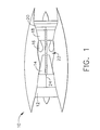
- Figure 1 is a schematic illustration of a gas turbine engine 10 including a low pressure compressor 12, a high pressure compressor 14, and a combustor 16.
- Engine 10 also includes a high pressure turbine 18 and a low pressure turbine 20.
- Combustor 16 includes an upstream side 22, and at least one dome (not shown).
- the gas turbine engine is a LMS 100 engine commercially available from General Electric Company, Cincinnati, Ohio.
- Airflow (not shown in Figure 1) from combustor 16 drives turbines 18 and 20.
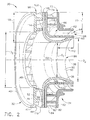
- FIG. 2 is a cross-sectional view of a portion of a combustor, such as combustor 16, that may be used with gas turbine engine 10.
- Combustor 16 includes a plurality of swirler assemblies 30, each of which includes a primary swirler 32, a secondary swirler 34, and a venturi 36 that is coupled to primary and secondary swirlers 32 and 34, respectively.
- Primary swirler 32, secondary swirler 34, and venturi 36 are each co-axially aligned with an axial centerline 38 of swirler assembly 30.
- Primary swirler 32 includes a substantially cylindrical body 40 defined by an outer perimeter 42, an inner surface 44, and an outer surface 46.
- a radial opening 48 extends between inner and outer surfaces 44 and 46, respectively.
- Outer surface 46 faces upstream, and inner surface 44 faces downstream when primary swirler 32 is coupled within combustor 16.
- a plurality of swirl vanes 50 extend circumferentially around opening 48 and extend between inner surface 44 and venturi 36.
- swirl vanes 50 extend between a radially outer, or upstream, wall 52 and a radially inner, or downstream, wall (not shown).
- primary swirl vanes 50 are spaced equidistantly apart and are oriented to induce a swirling action to a fuel/air mixture passing through swirler assembly 30.
- Secondary swirler 34 includes an inner wall 60, an outer wall 62, and a flow passage 64 extending therebetween.
- secondary swirler 34 is a two-piece assembly including inner wall 60 and outer wall 62.
- secondary swirler 34 may be an integrally-formed single piece assembly.
- Flow passage 64 has an upstream end 66 and a downstream end 68.
- Inner and outer walls 60 and 62, respectively, extend circumferentially around axial centerline 38 of swirler assembly 30.
- a flange portion 70 of secondary swirler 34 extends a distance 72 radially outward from flow passage upstream end 66, such that an outer perimeter 74 of flange portion 70 is substantially aligned with primary swirler outer perimeter 42.
- Flange portion 70 is in flow communication with flow passage 64 such that air is supplied to flow passage 64 through flange portion 70.
- a plurality of swirl vanes 80 extend from an inner surface 82 of outer wall 62 to an inner surface 84 of inner wall 60.
- inner and outer walls 60 and 62 are coupled together by brazing or welding secondary swirl vanes 80 to inner wall 60.
- outer wall 62 and inner wall 60 are formed integrally together and secondary swirl vanes 80 extend therebetween.
- secondary swirl vanes 80 are spaced equidistantly apart and are oriented to induce a swirling action to air channeled through flow passage 64.
- primary and secondary swirl vanes 50 and 80 are oriented in opposing directions, such that creating opposing swirl flows are created to facilitate mixing the fuel/air mixture when the secondary airflow and the primary airflow are combined.
- primary and secondary swirl vanes 50 and 80 are oriented in the same general direction, such that a similar swirl flow is created in the fuel/air mixture.
- Venturi 36 includes a substantially annular body 90 that has an inner surface 92 and an outer surface 94 that extends from an upstream end 96 of venturi 36 to a downstream end 98 of venturi 36.
- Venturi 36 includes a flange portion 100 positioned adjacent upstream end 96, and a throat portion 102 that extends from flange portion 100 to downstream end 98.
- Throat portion 102 extends substantially axially along swirler assembly axial centerline 38, and flange portion 100 extends radially outward a distance 106 from throat portion 102 such that an outer perimeter 108 of venturi flange portion 100 is generally aligned with primary swirler and secondary swirler outer perimeters 42 and 74, respectively.
- venturi flange portion 100 extends between primary swirler 32 and secondary swirler 34, such that venturi inner surface 92 is coupled against primary swirl vanes 50, and such that venturi outer surface 94 is coupled against an outer surface 110 of secondary swirler inner wall 60.
- inner surface 92 is coupled against primary swirler inner wall (not shown). More specifically, in the exemplary embodiment, flange portion 100 is coupled to primary and secondary swirlers 32 and 34, respectively, by a brazing operation or a welding operation.
- Venturi 36 extends downstream from primary swirler 32 such that airflow discharged from swirler 32 is channeled through venturi 36 which induces a swirling action to the airflow passing therethrough.
- airflow discharged into venturi 36 is channeled by flange portion 100 into throat portion 102.
- Throat portion 102 has a converging-diverging cross sectional profile that extends from flange portion 100 to downstream end 98 such that a minimum throat diameter D 1 is located a distance 112 upstream from downstream end 98. Accordingly, throat diameter D 1 is smaller than a diameter D 2 of primary swirler opening 48 and is smaller than a diameter D 3 of venturi 36 at downstream end 98.
- Secondary swirler 34 circumscribes venturi throat portion 102, and a portion of throat portion 102 is coupled to secondary swirler 34. Specifically, a portion 114 of venturi outer surface 94 is coupled to a portion 116 of secondary swirler inner wall outer surface 110 in a slide fit.
- the slide fit connection created between venturi 36 and secondary swirler 34 facilitates venturi 36 accommodating thermal expansion of secondary swirler 34, and also facilitates preventing ingestion of fuel, water and air between venturi 36 and secondary swirler 34 at downstream end 98.
- venturi downstream end 98 is coupled to secondary swirler 34 by a brazing or welding operation.
- a gap 120 is partially defined between venturi outer surface 94 and secondary swirler inner wall 60.
- gap 120 extends from venturi and secondary swirler flange portions 36 and 34, respectively, towards venturi downstream end 98 where venturi 36 and secondary swirler 34 are fixedly coupled together.
- Gap 120 creates a dead air cavity between venturi 36 and secondary swirler flow passage 64, which facilitates insulating venturi 36 from high temperatures associated with flow passage 64. Accordingly, gap 120 also facilitates reducing a rate of "explosive boiling" on venturi outer surface 94, thereby minimizing the need for a ceramic coating on venturi outer surface.
- venturi outer surface 94 is coated with a ceramic coating.
- venturi inner and/or outer surface 92 and/or 94 is coated with a thermal barrier coating to facilitate insulating venturi 36 from high temperatures.
- a plurality of openings 122 extend through secondary swirler inner wall 60 to couple flow passage 64 and gap 120 in flow communication. Openings 122 enable bleed air flowing through passage 64 to enter gap 120 to facilitate providing a purge flow through gap 120. The purge flow facilitates preventing the ingestion of fuel, water and air into gap 120. In an alternative embodiment, no openings are provided between flow passage 64 and gap 120.
- the individual components of swirler assembly 30, such as primary swirler 32, secondary swirler 34, and venturi 36 are manufactured and fabricated from different materials to facilitate optimizing wear and performance characteristics.
- primary swirler 32 is fabricated from a material selected to facilitate optimizing wear
- secondary swirler 34 is fabricated from a different material that is selected to facilitate optimizing thermal characteristics and bonding with venturi 36.
- venturi 36 is fabricated from a material selected to facilitate optimizing wear characteristics in the presence of sprayed fuel and water and to facilitate bonding with primary and secondary swirlers 32 and 34, respectively.
- the air/fuel mixture is channeled downstream through swirler assembly 30.
- the mixture is combined with swirling air from primary swirler 32.
- the swirling action facilitates spreading the mixture radially outward from swirler assembly 30 into the combustion zone.
- the mixture is channeled from the swirler assembly 30, it is further mixed with air supplied by secondary swirler flow passage 64.
- FIG 3 is a cross-sectional view of an alternative embodiment of a swirler assembly 130 that may be used in combination with a combustor, such as combustor 16 (shown in Figure 1).
- Swirler assembly 130 is substantially similar to swirler assembly 30 shown in Figure 2, and components in swirler assembly 130 that are identical to components of swirler assembly 130 are identified in Figure 3 using the same reference numerals used in Figure 2. Accordingly, swirler assembly 130 includes primary swirler 32, secondary swirler 34, and venturi 36.
- Primary swirler 32 includes radially outer wall 52, a radially inner wall 140, and a radial opening 142 extending between inner and outer walls 140 and 52, respectively.
- Each wall 52 and 140 has an inner surface 144 and 146, respectively, an outer surface 148 and 150, respectively, and an outer perimeter 152 and 154, respectively, extending therebetween.
- Outer surfaces 148 and 150 face upstream, and inner surfaces 144 and 146 face downstream when primary swirler 32 is properly positioned in combustor 16.
- Swirl vanes 50 extend circumferentially around opening 142 and extend between outer wall 140 and inner wall 52.
- Secondary swirler 34 includes inner wall 60, outer wall 62, and flow passage 64 extending therebetween.
- secondary swirler inner wall 60 has a ridge 160 extending outwardly towards primary swirler 32, and primary swirler inner wall 52 has an upper shoulder 162 for engaging ridge 160.
- Swirl vanes 80 extend within flange portion 70 from inner wall inner surface 84 to outer wall inner surface 82.
- Flange portion 70 is in flow communication with flow passage 64 such that air is supplied to flow passage 64 through flange portion 70.
- Venturi 36 includes body 90 that has inner surface 92 and outer surface 94 that extends from upstream end 96 to downstream end 98.
- Venturi 36 includes a flange portion 170 extending from throat portion 102 at upstream end 96. Flange portion 170 extends a distance 172 radially outward from throat portion 102 such that an outer perimeter 174 of venturi flange portion 170 is positioned between primary swirler 32 and secondary swirler 34.
- venturi outer perimeter 174 abuts a bottom edge 176 of ridge 160 extending from secondary swirler inner wall 60 and abuts a lower shoulder 178 of primary swirler inner wall 52.
- venturi flange portion 170 is coupled against primary swirler 32 and secondary swirler 34 in a slide fit.
- the slide fit connection created between venturi 36 and primary and secondary swirlers 32 and 34, respectively, facilitates venturi 36 accommodating thermal expansion of swirlers 32 and 34, and also facilitates preventing ingestion of fuel, water and/or air between venturi 36 and swirlers 32 and/or 34.
- venturi flange portion 170 is coupled to primary and/or secondary swirlers 32 and/or 34, respectively, by a brazing or welding operation.
- Secondary swirler 34 circumscribes venturi throat portion 102, and a portion 180 of throat portion 102 is coupled to secondary swirler 34.
- venturi outer surface portion 114 is coupled to secondary swirler inner wall 60 at downstream end 98 by a brazing operation or a welding operation to facilitate preventing ingestion of fuel, water and air between venturi 36 and secondary swirler 34.
- outer surface 94 is coupled to inner wall 60 via a slide fit connection.
- Gap 120 is partially defined between venturi outer surface 94 and secondary swirler inner wall 60.
- gap 120 extends from venturi and secondary swirler flange portions 70 and 170, respectively, towards venturi downstream end 98 where venturi 36 and secondary swirler 34 are fixedly coupled together.
- openings 122 extend between flow passage 64 and gap 120 so that flow passage 64 and gap 120 are in flow communication. In an alternative embodiment, no openings are provided between flow passage 64 and gap 120.
- the above-described combustor system for a gas turbine engine is cost-effective and reliable.
- the combustor system includes a multi component swirler assembly that includes a primary swirler, a secondary swirler and a venturi.
- a dead air gap is provided between the venturi and at least one of the swirlers which facilitates cooling the venturi, and openings are provided between the venturi and the air flow passage such that the air gap and the flow passage are in flow communication.
- the components are slide fit together, the components facilitate allowing thermal expansion to occur therebetween.
- the swirler assembly facilitates extending a useful life of the combustor in a reliable and cost-effective manner.
- swirler assemblies Exemplary embodiments of swirler assemblies are described above in detail.
- the assemblies are not limited to the specific embodiments described herein, but rather, components of each assembly may be utilized independently and separately from other components described herein.
- Each swirler assembly component can also be used in combination with other swirler assembly components.
Landscapes
- Engineering & Computer Science (AREA)
- Chemical & Material Sciences (AREA)
- Combustion & Propulsion (AREA)
- Mechanical Engineering (AREA)
- General Engineering & Computer Science (AREA)
Abstract
A method facilitates fabricating a gas turbine engine swirler assembly (30). The
method comprises coupling a (36) venturi to a primary swirler (32), and
coupling the venturi to a secondary swirler (34) such that a gap (120) is
defined between a portion of the venturi and a portion of one of the primary
swirler and the secondary swirler.
Description
- This application relates generally to gas turbine engines and, more particularly, to combustors for gas turbine engine.
- Combustors are used to ignite fuel and air mixtures in gas turbine engines. Known combustors include at least one dome attached to a combustor liner that defines a combustion zone. Fuel injectors are attached to the combustor in flow communication with the dome and supply fuel to the combustion zone. Fuel enters the combustor through a dome assembly attached to a spectacle or dome plate.
- At least some known dome assemblies include an air swirler that is secured to the dome plate, and is radially outward from a venturi. The venturi is divergent and facilitates mixing the air and fuel, and spreading the mixture radially outwardly into the combustion zone.
- To facilitate nitrous oxide (NOx) abatement, water is injected into at least some known gas turbine engine combustors. However, continued operation with water injection may cause material degradation and/or erosion of the combustor venturi. More specifically, because the water and fuel are typically sprayed through the combustor venturi, as the water contacts the venturi, the high operating temperatures of the water may cause the water to quickly change from a liquid to steam in an effect known as "explosive boiling". Over time, such explosive boiling may lead to material degradation and/or removal at the point of impact between the water and the venturi. To facilitate reducing the effects of the water injection, at least some known combustor venturis are coated with a ceramic coating. Although such coatings may decrease the effect of the water injection, such coatings also increase the fabrication time and costs.
- In one embodiment of the invention, a method for fabricating a gas turbine engine combustor is provided. The method comprises coupling a venturi to a primary swirler, and coupling the venturi to a secondary swirler such that a gap is defined between a portion of the venturi and a portion of one of the primary swirler and the secondary swirler.
- In another embodiment, a combustor for a gas turbine engine is provided. The combustor includes a venturi and a secondary swirler extending circumferentially around the venturi. The secondary swirler is coupled to the venturi such that a gap is defined between a portion of the secondary swirler and the venturi.
- In a further embodiment, a gas turbine engine is provided. The gas turbine engine includes a combustor including at least one annular air swirler and an annular venturi. The annular air swirler is coupled to the venturi such that a gap is defined between a portion of the air swirler and the venturi.
- The invention will now be described in greater detail, by way of example, with reference to the drawings, in which:-
- Figure 1 is a schematic illustration of a gas turbine engine;
- Figure 2 is a cross-sectional view of a portion of a combustor that may be used with the gas turbine engine shown in Figure 1; and
- Figure 3 is a cross-sectional view of a portion of an alternative embodiment of a combustor that may be used with the gas turbine engine shown in Figure 1.
-
- Figure 1 is a schematic illustration of a
gas turbine engine 10 including alow pressure compressor 12, ahigh pressure compressor 14, and acombustor 16.Engine 10 also includes ahigh pressure turbine 18 and alow pressure turbine 20. Combustor 16 includes anupstream side 22, and at least one dome (not shown). In one embodiment, the gas turbine engine is a LMS 100 engine commercially available from General Electric Company, Cincinnati, Ohio. - In operation, air flows through
low pressure compressor 12 and compressed air is supplied fromlow pressure compressor 12 tohigh pressure compressor 14. The highly compressed air is delivered tocombustor 16. Airflow (not shown in Figure 1) fromcombustor 16drives turbines - Figure 2 is a cross-sectional view of a portion of a combustor, such as
combustor 16, that may be used withgas turbine engine 10.Combustor 16 includes a plurality ofswirler assemblies 30, each of which includes aprimary swirler 32, asecondary swirler 34, and aventuri 36 that is coupled to primary andsecondary swirlers Primary swirler 32,secondary swirler 34, andventuri 36 are each co-axially aligned with anaxial centerline 38 ofswirler assembly 30. -
Primary swirler 32 includes a substantiallycylindrical body 40 defined by anouter perimeter 42, aninner surface 44, and anouter surface 46. Aradial opening 48 extends between inner andouter surfaces Outer surface 46 faces upstream, andinner surface 44 faces downstream whenprimary swirler 32 is coupled withincombustor 16. A plurality ofswirl vanes 50 extend circumferentially around opening 48 and extend betweeninner surface 44 andventuri 36. In an alternative embodiment, swirl vanes 50 extend between a radially outer, or upstream,wall 52 and a radially inner, or downstream, wall (not shown). In the exemplary embodiment,primary swirl vanes 50 are spaced equidistantly apart and are oriented to induce a swirling action to a fuel/air mixture passing throughswirler assembly 30. -
Secondary swirler 34 includes aninner wall 60, anouter wall 62, and aflow passage 64 extending therebetween. In the exemplary embodiment,secondary swirler 34 is a two-piece assembly includinginner wall 60 andouter wall 62. Alternatively,secondary swirler 34 may be an integrally-formed single piece assembly.Flow passage 64 has anupstream end 66 and adownstream end 68. Inner andouter walls axial centerline 38 ofswirler assembly 30. Aflange portion 70 ofsecondary swirler 34 extends adistance 72 radially outward from flow passage upstreamend 66, such that anouter perimeter 74 offlange portion 70 is substantially aligned with primary swirlerouter perimeter 42.Flange portion 70 is in flow communication withflow passage 64 such that air is supplied toflow passage 64 throughflange portion 70. - A plurality of
swirl vanes 80 extend from aninner surface 82 ofouter wall 62 to aninner surface 84 ofinner wall 60. In the exemplary embodiment, inner andouter walls secondary swirl vanes 80 toinner wall 60. In an alternative embodiment,outer wall 62 andinner wall 60 are formed integrally together andsecondary swirl vanes 80 extend therebetween. In the exemplary embodiment,secondary swirl vanes 80 are spaced equidistantly apart and are oriented to induce a swirling action to air channeled throughflow passage 64. In the exemplary embodiment, primary andsecondary swirl vanes secondary swirl vanes - Venturi 36 includes a substantially
annular body 90 that has aninner surface 92 and anouter surface 94 that extends from anupstream end 96 ofventuri 36 to adownstream end 98 ofventuri 36. Venturi 36 includes aflange portion 100 positioned adjacentupstream end 96, and athroat portion 102 that extends fromflange portion 100 to downstreamend 98.Throat portion 102 extends substantially axially along swirler assemblyaxial centerline 38, andflange portion 100 extends radially outward adistance 106 fromthroat portion 102 such that anouter perimeter 108 ofventuri flange portion 100 is generally aligned with primary swirler and secondary swirlerouter perimeters - In the exemplary embodiment,
venturi flange portion 100 extends betweenprimary swirler 32 andsecondary swirler 34, such that venturiinner surface 92 is coupled againstprimary swirl vanes 50, and such that venturiouter surface 94 is coupled against anouter surface 110 of secondary swirlerinner wall 60. In an alternative embodiment,inner surface 92 is coupled against primary swirler inner wall (not shown). More specifically, in the exemplary embodiment,flange portion 100 is coupled to primary andsecondary swirlers - Venturi 36 extends downstream from
primary swirler 32 such that airflow discharged fromswirler 32 is channeled throughventuri 36 which induces a swirling action to the airflow passing therethrough. Specifically, airflow discharged intoventuri 36 is channeled byflange portion 100 intothroat portion 102.Throat portion 102 has a converging-diverging cross sectional profile that extends fromflange portion 100 todownstream end 98 such that a minimum throat diameter D1 is located adistance 112 upstream fromdownstream end 98. Accordingly, throat diameter D1 is smaller than a diameter D2 of primary swirler opening 48 and is smaller than a diameter D3 ofventuri 36 atdownstream end 98. -
Secondary swirler 34 circumscribesventuri throat portion 102, and a portion ofthroat portion 102 is coupled tosecondary swirler 34. Specifically, aportion 114 of venturiouter surface 94 is coupled to aportion 116 of secondary swirler inner wallouter surface 110 in a slide fit. The slide fit connection created betweenventuri 36 andsecondary swirler 34 facilitatesventuri 36 accommodating thermal expansion ofsecondary swirler 34, and also facilitates preventing ingestion of fuel, water and air betweenventuri 36 andsecondary swirler 34 atdownstream end 98. In an alternative embodiment, venturidownstream end 98 is coupled tosecondary swirler 34 by a brazing or welding operation. - A
gap 120 is partially defined between venturiouter surface 94 and secondary swirlerinner wall 60. In the exemplary embodiment,gap 120 extends from venturi and secondaryswirler flange portions downstream end 98 whereventuri 36 andsecondary swirler 34 are fixedly coupled together.Gap 120 creates a dead air cavity betweenventuri 36 and secondaryswirler flow passage 64, which facilitates insulatingventuri 36 from high temperatures associated withflow passage 64. Accordingly,gap 120 also facilitates reducing a rate of "explosive boiling" on venturiouter surface 94, thereby minimizing the need for a ceramic coating on venturi outer surface. However, in an alternative embodiment, venturiouter surface 94 is coated with a ceramic coating. In another alternative embodiment, venturi inner and/orouter surface 92 and/or 94 is coated with a thermal barrier coating to facilitate insulatingventuri 36 from high temperatures. - In the exemplary embodiment, a plurality of
openings 122 extend through secondary swirlerinner wall 60 tocouple flow passage 64 andgap 120 in flow communication.Openings 122 enable bleed air flowing throughpassage 64 to entergap 120 to facilitate providing a purge flow throughgap 120. The purge flow facilitates preventing the ingestion of fuel, water and air intogap 120. In an alternative embodiment, no openings are provided betweenflow passage 64 andgap 120. - In the exemplary embodiment, the individual components of
swirler assembly 30, such asprimary swirler 32,secondary swirler 34, andventuri 36 are manufactured and fabricated from different materials to facilitate optimizing wear and performance characteristics. For example,primary swirler 32 is fabricated from a material selected to facilitate optimizing wear, andsecondary swirler 34 is fabricated from a different material that is selected to facilitate optimizing thermal characteristics and bonding withventuri 36. Moreover,venturi 36 is fabricated from a material selected to facilitate optimizing wear characteristics in the presence of sprayed fuel and water and to facilitate bonding with primary and secondary swirlers 32 and 34, respectively. - During operation, the air/fuel mixture is channeled downstream through
swirler assembly 30. As the mixture is channeled throughprimary swirler opening 48, the mixture is combined with swirling air fromprimary swirler 32. The swirling action facilitates spreading the mixture radially outward fromswirler assembly 30 into the combustion zone. As the mixture is channeled from theswirler assembly 30, it is further mixed with air supplied by secondaryswirler flow passage 64. - Figure 3 is a cross-sectional view of an alternative embodiment of a
swirler assembly 130 that may be used in combination with a combustor, such as combustor 16 (shown in Figure 1).Swirler assembly 130 is substantially similar toswirler assembly 30 shown in Figure 2, and components inswirler assembly 130 that are identical to components ofswirler assembly 130 are identified in Figure 3 using the same reference numerals used in Figure 2. Accordingly,swirler assembly 130 includesprimary swirler 32,secondary swirler 34, andventuri 36. -
Primary swirler 32 includes radiallyouter wall 52, a radiallyinner wall 140, and aradial opening 142 extending between inner andouter walls wall inner surface outer surface outer perimeter Outer surfaces inner surfaces primary swirler 32 is properly positioned incombustor 16.Swirl vanes 50 extend circumferentially around opening 142 and extend betweenouter wall 140 andinner wall 52. -
Secondary swirler 34 includesinner wall 60,outer wall 62, and flowpassage 64 extending therebetween. In the exemplary embodiment, secondary swirlerinner wall 60 has a ridge 160 extending outwardly towardsprimary swirler 32, and primary swirlerinner wall 52 has anupper shoulder 162 for engaging ridge 160.Swirl vanes 80 extend withinflange portion 70 from inner wallinner surface 84 to outer wallinner surface 82.Flange portion 70 is in flow communication withflow passage 64 such that air is supplied to flowpassage 64 throughflange portion 70. -
Venturi 36 includesbody 90 that hasinner surface 92 andouter surface 94 that extends fromupstream end 96 todownstream end 98.Venturi 36 includes aflange portion 170 extending fromthroat portion 102 atupstream end 96.Flange portion 170 extends adistance 172 radially outward fromthroat portion 102 such that an outer perimeter 174 ofventuri flange portion 170 is positioned betweenprimary swirler 32 andsecondary swirler 34. In the exemplary embodiment, venturi outer perimeter 174 abuts abottom edge 176 of ridge 160 extending from secondary swirlerinner wall 60 and abuts alower shoulder 178 of primary swirlerinner wall 52. Specifically,venturi flange portion 170 is coupled againstprimary swirler 32 andsecondary swirler 34 in a slide fit. The slide fit connection created betweenventuri 36 and primary and secondary swirlers 32 and 34, respectively, facilitatesventuri 36 accommodating thermal expansion ofswirlers venturi 36 and swirlers 32 and/or 34. In an alternative embodiment,venturi flange portion 170 is coupled to primary and/orsecondary swirlers 32 and/or 34, respectively, by a brazing or welding operation. -
Secondary swirler 34 circumscribesventuri throat portion 102, and a portion 180 ofthroat portion 102 is coupled tosecondary swirler 34. Specifically, venturiouter surface portion 114 is coupled to secondary swirlerinner wall 60 atdownstream end 98 by a brazing operation or a welding operation to facilitate preventing ingestion of fuel, water and air betweenventuri 36 andsecondary swirler 34. In an alternative embodiment,outer surface 94 is coupled toinner wall 60 via a slide fit connection. -
Gap 120 is partially defined between venturiouter surface 94 and secondary swirlerinner wall 60. In the exemplary embodiment,gap 120 extends from venturi and secondaryswirler flange portions downstream end 98 whereventuri 36 andsecondary swirler 34 are fixedly coupled together. In the exemplary embodiment,openings 122 extend betweenflow passage 64 andgap 120 so thatflow passage 64 andgap 120 are in flow communication. In an alternative embodiment, no openings are provided betweenflow passage 64 andgap 120. - The above-described combustor system for a gas turbine engine is cost-effective and reliable. The combustor system includes a multi component swirler assembly that includes a primary swirler, a secondary swirler and a venturi. A dead air gap is provided between the venturi and at least one of the swirlers which facilitates cooling the venturi, and openings are provided between the venturi and the air flow passage such that the air gap and the flow passage are in flow communication. Furthermore, because the components are slide fit together, the components facilitate allowing thermal expansion to occur therebetween. As a result, the swirler assembly facilitates extending a useful life of the combustor in a reliable and cost-effective manner.
- Exemplary embodiments of swirler assemblies are described above in detail. The assemblies are not limited to the specific embodiments described herein, but rather, components of each assembly may be utilized independently and separately from other components described herein. Each swirler assembly component can also be used in combination with other swirler assembly components.
Claims (10)
- A combustor (16) for a gas turbine engine (10), said combustor comprising:a venturi (36); anda secondary swirler (34) extending circumferentially around said venturi, said secondary swirler coupled to said venturi such that a gap (120) is defined between a portion of said secondary swirler and said venturi.
- A combustor (16) in accordance with Claim 1 further comprising a primary swirler (32) coupled to said venturi (36) such that said venturi is between said primary and secondary (34) swirlers.
- A combustor (16) in accordance with Claim 2 wherein at least a portion of said venturi (36) is slidably coupled to a portion of one of said primary and said secondary swirlers (32) and (34).
- A combustor (16) in accordance with Claim 2 wherein at least a portion of said venturi (36) is coupled to a portion of one of said primary and said secondary swirlers (32) and (34) in a slide fit, said slide fit facilitates accommodating thermal growth of at least one of said primary and said secondary swirler with respect to said venturi.
- A combustor (16) in accordance with Claim 1 wherein said secondary swirler (34) comprises a secondary air passage (64) extending therethrough and a plurality of openings (122), said openings couple said secondary air passage and said gap (120) in flow communication.
- A combustor (16) in accordance with Claim 1 wherein said gap (120) is defined between a radially outer surface (94) of said venturi (36) and a radially inner surface (110) of said secondary swirler (34), said venturi radially outer surface comprises a layer of thermal barrier coating.
- A combustor (16) in accordance with Claim 1 wherein said gap (120) facilitates reducing an operating temperature of said venturi (36).
- A gas turbine engine (10) comprising a combustor (16) comprising at least one annular air swirler (34) and an annular venturi (36), said annular air swirler coupled to said venturi such that a gap (120) is defined between a portion of said air swirler and said venturi.
- A gas turbine engine (10) in accordance with Claim 8 wherein said gap (120) facilitates reducing an operating temperature of said venturi (36), wherein at least a portion of said at least one annular air swirler (34) is coupled in a slide fit against said venturi.
- A gas turbine engine (10) in accordance with Claim 8 wherein said air swirler (34) defines a flow passageway (64) extending therethrough, said at least one air swirler comprises a plurality of openings (122) extending in flow communication between said flow passageway and said gap (120).
Applications Claiming Priority (2)
| Application Number | Priority Date | Filing Date | Title |
|---|---|---|---|
| US826432 | 1997-03-18 | ||
| US10/826,432 US20050229600A1 (en) | 2004-04-16 | 2004-04-16 | Methods and apparatus for fabricating gas turbine engine combustors |
Publications (1)
| Publication Number | Publication Date |
|---|---|
| EP1586819A2 true EP1586819A2 (en) | 2005-10-19 |
Family
ID=34940817
Family Applications (1)
| Application Number | Title | Priority Date | Filing Date |
|---|---|---|---|
| EP05252318A Withdrawn EP1586819A2 (en) | 2004-04-16 | 2005-04-14 | Swirler assembly for gas turbine engine combustors |
Country Status (4)
| Country | Link |
|---|---|
| US (1) | US20050229600A1 (en) |
| EP (1) | EP1586819A2 (en) |
| JP (1) | JP2005308389A (en) |
| CA (1) | CA2503878A1 (en) |
Cited By (2)
| Publication number | Priority date | Publication date | Assignee | Title |
|---|---|---|---|---|
| EP2071242A1 (en) * | 2007-12-14 | 2009-06-17 | Snecma | Device for injecting a mixture of air and fuel into a combustion chamber of a turbomachine |
| FR3033030A1 (en) * | 2015-02-20 | 2016-08-26 | Snecma | AIR-FUEL MIX INJECTION SYSTEM IN AN AIRCRAFT TURBOMACHINE COMBUSTION CHAMBER, COMPRISING A PERFORATED AIR INJECTION HOLES VENTURI |
Families Citing this family (15)
| Publication number | Priority date | Publication date | Assignee | Title |
|---|---|---|---|---|
| US8607569B2 (en) * | 2009-07-01 | 2013-12-17 | General Electric Company | Methods and systems to thermally protect fuel nozzles in combustion systems |
| US9920693B2 (en) | 2013-03-14 | 2018-03-20 | United Technologies Corporation | Hollow-wall heat shield for fuel injector component |
| WO2015050986A1 (en) * | 2013-10-04 | 2015-04-09 | United Technologies Corporation | Swirler for a turbine engine combustor |
| US9435540B2 (en) | 2013-12-11 | 2016-09-06 | General Electric Company | Fuel injector with premix pilot nozzle |
| US10030869B2 (en) | 2014-11-26 | 2018-07-24 | General Electric Company | Premix fuel nozzle assembly |
| FR3029608B1 (en) | 2014-12-03 | 2017-01-13 | Snecma | AIR INTAKE CROWN FOR TURBOMACHINE COMBUSTION CHAMBER INJECTION SYSTEM AND FUEL ATOMIZATION METHOD IN INJECTION SYSTEM COMPRISING SAID AIR INTAKE CROWN |
| US9982892B2 (en) * | 2015-04-16 | 2018-05-29 | General Electric Company | Fuel nozzle assembly including a pilot nozzle |
| US9927126B2 (en) * | 2015-06-10 | 2018-03-27 | General Electric Company | Prefilming air blast (PAB) pilot for low emissions combustors |
| US10184665B2 (en) | 2015-06-10 | 2019-01-22 | General Electric Company | Prefilming air blast (PAB) pilot having annular splitter surrounding a pilot fuel injector |
| US11598526B2 (en) | 2021-04-16 | 2023-03-07 | General Electric Company | Combustor swirl vane apparatus |
| US11802693B2 (en) | 2021-04-16 | 2023-10-31 | General Electric Company | Combustor swirl vane apparatus |
| US11846423B2 (en) | 2021-04-16 | 2023-12-19 | General Electric Company | Mixer assembly for gas turbine engine combustor |
| US11428411B1 (en) * | 2021-05-18 | 2022-08-30 | General Electric Company | Swirler with rifled venturi for dynamics mitigation |
| US12072099B2 (en) * | 2021-12-21 | 2024-08-27 | General Electric Company | Gas turbine fuel nozzle having a lip extending from the vanes of a swirler |
| EP4202304B1 (en) | 2021-12-21 | 2025-02-26 | General Electric Company | Turbine engine with fuel nozzle and swirler |
Family Cites Families (20)
| Publication number | Priority date | Publication date | Assignee | Title |
|---|---|---|---|---|
| US4584834A (en) * | 1982-07-06 | 1986-04-29 | General Electric Company | Gas turbine engine carburetor |
| DE3642122C1 (en) * | 1986-12-10 | 1988-06-09 | Mtu Muenchen Gmbh | Fuel injector |
| US4938019A (en) * | 1987-10-16 | 1990-07-03 | Fuel Systems Textron Inc. | Fuel nozzle and igniter assembly |
| US5220786A (en) * | 1991-03-08 | 1993-06-22 | General Electric Company | Thermally protected venturi for combustor dome |
| US5623827A (en) * | 1995-01-26 | 1997-04-29 | General Electric Company | Regenerative cooled dome assembly for a gas turbine engine combustor |
| US6571559B1 (en) * | 1998-04-03 | 2003-06-03 | General Electric Company | Anti-carboning fuel-air mixer for a gas turbine engine combustor |
| US6047539A (en) * | 1998-04-30 | 2000-04-11 | General Electric Company | Method of protecting gas turbine combustor components against water erosion and hot corrosion |
| US6474070B1 (en) * | 1998-06-10 | 2002-11-05 | General Electric Company | Rich double dome combustor |
| US6286302B1 (en) * | 1999-04-01 | 2001-09-11 | General Electric Company | Venturi for use in the swirl cup package of a gas turbine combustor having water injected therein |
| US6415594B1 (en) * | 2000-05-31 | 2002-07-09 | General Electric Company | Methods and apparatus for reducing gas turbine engine emissions |
| US6389815B1 (en) * | 2000-09-08 | 2002-05-21 | General Electric Company | Fuel nozzle assembly for reduced exhaust emissions |
| US6427446B1 (en) * | 2000-09-19 | 2002-08-06 | Power Systems Mfg., Llc | Low NOx emission combustion liner with circumferentially angled film cooling holes |
| US6405523B1 (en) * | 2000-09-29 | 2002-06-18 | General Electric Company | Method and apparatus for decreasing combustor emissions |
| US6363726B1 (en) * | 2000-09-29 | 2002-04-02 | General Electric Company | Mixer having multiple swirlers |
| US6622488B2 (en) * | 2001-03-21 | 2003-09-23 | Parker-Hannifin Corporation | Pure airblast nozzle |
| US6418726B1 (en) * | 2001-05-31 | 2002-07-16 | General Electric Company | Method and apparatus for controlling combustor emissions |
| FR2827367B1 (en) * | 2001-07-16 | 2003-10-17 | Snecma Moteurs | AEROMECHANICAL INJECTION SYSTEM WITH ANTI-RETURN PRIMARY LOCK |
| US6655027B2 (en) * | 2002-01-15 | 2003-12-02 | General Electric Company | Methods for assembling gas turbine engine combustors |
| EP1499800B1 (en) * | 2002-04-26 | 2011-06-29 | Rolls-Royce Corporation | Fuel premixing module for gas turbine engine combustor |
| US6871501B2 (en) * | 2002-12-03 | 2005-03-29 | General Electric Company | Method and apparatus to decrease gas turbine engine combustor emissions |
-
2004
- 2004-04-16 US US10/826,432 patent/US20050229600A1/en not_active Abandoned
-
2005
- 2005-04-07 CA CA002503878A patent/CA2503878A1/en not_active Abandoned
- 2005-04-14 EP EP05252318A patent/EP1586819A2/en not_active Withdrawn
- 2005-04-15 JP JP2005117632A patent/JP2005308389A/en active Pending
Cited By (4)
| Publication number | Priority date | Publication date | Assignee | Title |
|---|---|---|---|---|
| EP2071242A1 (en) * | 2007-12-14 | 2009-06-17 | Snecma | Device for injecting a mixture of air and fuel into a combustion chamber of a turbomachine |
| FR2925146A1 (en) * | 2007-12-14 | 2009-06-19 | Snecma Sa | SYSTEM FOR INJECTING A MIXTURE OF AIR AND FUEL IN A TURBOMACHINE COMBUSTION CHAMBER |
| US8312723B2 (en) | 2007-12-14 | 2012-11-20 | Snecma | System for injecting a mixture of air and fuel into a turbomachine combustion chamber |
| FR3033030A1 (en) * | 2015-02-20 | 2016-08-26 | Snecma | AIR-FUEL MIX INJECTION SYSTEM IN AN AIRCRAFT TURBOMACHINE COMBUSTION CHAMBER, COMPRISING A PERFORATED AIR INJECTION HOLES VENTURI |
Also Published As
| Publication number | Publication date |
|---|---|
| JP2005308389A (en) | 2005-11-04 |
| US20050229600A1 (en) | 2005-10-20 |
| CA2503878A1 (en) | 2005-10-16 |
Similar Documents
| Publication | Publication Date | Title |
|---|---|---|
| EP1586819A2 (en) | Swirler assembly for gas turbine engine combustors | |
| EP1253379B1 (en) | Methods and apparatus for cooling gas turbine engine combustors | |
| US7716931B2 (en) | Method and apparatus for assembling gas turbine engine | |
| CA2578565C (en) | Method and apparatus for gas turbine engines | |
| US6871501B2 (en) | Method and apparatus to decrease gas turbine engine combustor emissions | |
| US9714767B2 (en) | Premix fuel nozzle assembly | |
| US7131273B2 (en) | Gas turbine engine carburetor with flat retainer connecting primary and secondary swirlers | |
| EP1253380B1 (en) | Methods and apparatus for cooling gas turbine engine combustors | |
| US7080515B2 (en) | Gas turbine can annular combustor | |
| JP4733195B2 (en) | Fuel spray system for gas turbine engine | |
| CN100520185C (en) | Combustor dome assembly of a gas turbine engine having a free floating swirler | |
| EP3282191B1 (en) | Pilot premix nozzle and fuel nozzle assembly | |
| EP1258681B1 (en) | Methods and apparatus for cooling gas turbine engine combustors | |
| US7340900B2 (en) | Method and apparatus for decreasing combustor acoustics | |
| CA2868732A1 (en) | Turbomachine combustor assembly | |
| EP3524886B1 (en) | An air swirler arrangement for a fuel injector of a combustion chamber | |
| KR102587366B1 (en) | Floating primary vane swirler | |
| US10030869B2 (en) | Premix fuel nozzle assembly | |
| EP1394470A2 (en) | Multiple-domes annular combustor for a gas turbine engine | |
| US20170363294A1 (en) | Pilot premix nozzle and fuel nozzle assembly | |
| US20170356652A1 (en) | Combustor Effusion Plate Assembly |
Legal Events
| Date | Code | Title | Description |
|---|---|---|---|
| PUAI | Public reference made under article 153(3) epc to a published international application that has entered the european phase |
Free format text: ORIGINAL CODE: 0009012 |
|
| AK | Designated contracting states |
Kind code of ref document: A2 Designated state(s): AT BE BG CH CY CZ DE DK EE ES FI FR GB GR HU IE IS IT LI LT LU MC NL PL PT RO SE SI SK TR |
|
| AX | Request for extension of the european patent |
Extension state: AL BA HR LV MK YU |
|
| STAA | Information on the status of an ep patent application or granted ep patent |
Free format text: STATUS: THE APPLICATION IS DEEMED TO BE WITHDRAWN |
|
| 18D | Application deemed to be withdrawn |
Effective date: 20121101 |