EP1586764A1 - Fuel supply apparatus - Google Patents
Fuel supply apparatus Download PDFInfo
- Publication number
- EP1586764A1 EP1586764A1 EP05075851A EP05075851A EP1586764A1 EP 1586764 A1 EP1586764 A1 EP 1586764A1 EP 05075851 A EP05075851 A EP 05075851A EP 05075851 A EP05075851 A EP 05075851A EP 1586764 A1 EP1586764 A1 EP 1586764A1
- Authority
- EP
- European Patent Office
- Prior art keywords
- fuel
- throttle
- fuel supply
- attaching
- communicating
- Prior art date
- Legal status (The legal status is an assumption and is not a legal conclusion. Google has not performed a legal analysis and makes no representation as to the accuracy of the status listed.)
- Granted
Links
Images






Classifications
-
- F—MECHANICAL ENGINEERING; LIGHTING; HEATING; WEAPONS; BLASTING
- F02—COMBUSTION ENGINES; HOT-GAS OR COMBUSTION-PRODUCT ENGINE PLANTS
- F02M—SUPPLYING COMBUSTION ENGINES IN GENERAL WITH COMBUSTIBLE MIXTURES OR CONSTITUENTS THEREOF
- F02M69/00—Low-pressure fuel-injection apparatus ; Apparatus with both continuous and intermittent injection; Apparatus injecting different types of fuel
- F02M69/46—Details, component parts or accessories not provided for in, or of interest apart from, the apparatus covered by groups F02M69/02 - F02M69/44
- F02M69/462—Arrangement of fuel conduits, e.g. with valves for maintaining pressure in the pipes after the engine being shut-down
- F02M69/465—Arrangement of fuel conduits, e.g. with valves for maintaining pressure in the pipes after the engine being shut-down of fuel rails
-
- F—MECHANICAL ENGINEERING; LIGHTING; HEATING; WEAPONS; BLASTING
- F02—COMBUSTION ENGINES; HOT-GAS OR COMBUSTION-PRODUCT ENGINE PLANTS
- F02D—CONTROLLING COMBUSTION ENGINES
- F02D9/00—Controlling engines by throttling air or fuel-and-air induction conduits or exhaust conduits
- F02D9/08—Throttle valves specially adapted therefor; Arrangements of such valves in conduits
- F02D9/10—Throttle valves specially adapted therefor; Arrangements of such valves in conduits having pivotally-mounted flaps
- F02D9/109—Throttle valves specially adapted therefor; Arrangements of such valves in conduits having pivotally-mounted flaps having two or more flaps
- F02D9/1095—Rotating on a common axis, e.g. having a common shaft
-
- F—MECHANICAL ENGINEERING; LIGHTING; HEATING; WEAPONS; BLASTING
- F02—COMBUSTION ENGINES; HOT-GAS OR COMBUSTION-PRODUCT ENGINE PLANTS
- F02M—SUPPLYING COMBUSTION ENGINES IN GENERAL WITH COMBUSTIBLE MIXTURES OR CONSTITUENTS THEREOF
- F02M35/00—Combustion-air cleaners, air intakes, intake silencers, or induction systems specially adapted for, or arranged on, internal-combustion engines
- F02M35/10—Air intakes; Induction systems
- F02M35/10209—Fluid connections to the air intake system; their arrangement of pipes, valves or the like
- F02M35/10216—Fuel injectors; Fuel pipes or rails; Fuel pumps or pressure regulators
-
- F—MECHANICAL ENGINEERING; LIGHTING; HEATING; WEAPONS; BLASTING
- F02—COMBUSTION ENGINES; HOT-GAS OR COMBUSTION-PRODUCT ENGINE PLANTS
- F02M—SUPPLYING COMBUSTION ENGINES IN GENERAL WITH COMBUSTIBLE MIXTURES OR CONSTITUENTS THEREOF
- F02M69/00—Low-pressure fuel-injection apparatus ; Apparatus with both continuous and intermittent injection; Apparatus injecting different types of fuel
- F02M69/04—Injectors peculiar thereto
- F02M69/042—Positioning of injectors with respect to engine, e.g. in the air intake conduit
- F02M69/044—Positioning of injectors with respect to engine, e.g. in the air intake conduit for injecting into the intake conduit downstream of an air throttle valve
-
- F—MECHANICAL ENGINEERING; LIGHTING; HEATING; WEAPONS; BLASTING
- F02—COMBUSTION ENGINES; HOT-GAS OR COMBUSTION-PRODUCT ENGINE PLANTS
- F02M—SUPPLYING COMBUSTION ENGINES IN GENERAL WITH COMBUSTIBLE MIXTURES OR CONSTITUENTS THEREOF
- F02M69/00—Low-pressure fuel-injection apparatus ; Apparatus with both continuous and intermittent injection; Apparatus injecting different types of fuel
- F02M69/46—Details, component parts or accessories not provided for in, or of interest apart from, the apparatus covered by groups F02M69/02 - F02M69/44
- F02M69/54—Arrangement of fuel pressure regulators
-
- F—MECHANICAL ENGINEERING; LIGHTING; HEATING; WEAPONS; BLASTING
- F02—COMBUSTION ENGINES; HOT-GAS OR COMBUSTION-PRODUCT ENGINE PLANTS
- F02M—SUPPLYING COMBUSTION ENGINES IN GENERAL WITH COMBUSTIBLE MIXTURES OR CONSTITUENTS THEREOF
- F02M2200/00—Details of fuel-injection apparatus, not otherwise provided for
- F02M2200/40—Fuel-injection apparatus with fuel accumulators, e.g. a fuel injector having an integrated fuel accumulator
Definitions
- the present invention relates to a fuel supply apparatus for supplying a fuel to an internal combustion engine, and more particularly to a fuel supply apparatus in a fuel injection type which injects and supplies fuel having pressure increased by a fuel pump toward inner sides of a plurality of intake pipes by a plurality of fuel injection valves.
- FIG. 22 and 23 A conventional fuel supply apparatus using a fuel injection valve is shown in Figs. 22 and 23.
- Fig. 22 is an upper plan view in the case of seeing a fuel supply apparatus from the above
- Fig. 23 is a vertical cross sectional view of a main portion in a line Z-Z of Fig. 22.
- Reference numeral (80) denotes a first throttle body in which a first intake path (81) is provided therethrough in a vertical direction, in Fig. 23.
- the first intake path (81) is opened and closed by a first throttle valve (83) attached to a first throttle valve shaft (82).
- An upper opening (81a) of the first intake path (81) communicates with an inner side of an air cleaner box (84) arranged in an upper side via a duct or the like, a lower opening (81b) of the first intake path (81) is connected to a first intake pipe (85) bent toward the other side A in accordance with extending close to a lower side in Fig. 23, and a downstream side of the first intake pipe (85) is connected to a first cylinder (86), for example, constituting a V-type engine.
- Reference symbol (J1) denotes an electromagnetic type first fuel injection valve attached to the first throttle body (80).
- a lower side of the first fuel injection valve (J1) is inserted and supported to the first throttle body (80), and an upper side thereof is inserted and supported to a first fuel supply pipe (87).
- the first fuel injection valve (J1) is pinched by the first throttle body (80) and the first fuel supply pipe (87) by screw fixing the first fuel supply pipe (87) to the first throttle body (80) via a screw (88).
- the first fuel injection valve (J1) is first arranged in one side B of the first throttle body (80), that is, one side outer surface (80b). Further, secondly, a lower injection hole (Ja) of the first fuel injection valve (J1) is arranged so as to be inclined toward a center of the first intake path (81). In other words, the first fuel injection valve (J1) is arranged in such a manner that the first throttle body (80) exists in one side outer surface (80b) and is inclined so as to lower the left side thereof in Fig. 23.
- a first fuel distribution path (87a) is provided through within the first fuel supply pipe (87), and a fuel inflow path (88) is connected to an opening in a left side C in Fig. 22 of the first fuel distribution path (87a).
- the fuel having the pressure increased by the fuel pump (not shown) is supplied to the fuel inflow path via a fuel pipe (89).
- Reference numeral (90) denotes a second throttle body in which a second intake path (91) is provided through in a vertical direction in Fig. 23.
- the second intake path (91) is opened and closed by a second throttle valve (93) attached to a second throttle valve shaft (92).
- An upper opening (91a) of the second intake path (91) communicates with an inner side of the air cleaner box (84) arranged in an upper side via a duct or the like, a lower opening (91b) of the second intake path (91) is connected to a second intake pipe (95) bent toward one side B in accordance with extending toward a lower side in Fig. 23, and a downstream side of the second intake pipe (95) is connected to a second cylinder (96), for example, constituting a V-type engine.
- Reference symbol (J2) denotes an electromagnetic type second fuel injection valve attached to the second throttle body (90) .
- a lower side of the second fuel injection valve (J2) is inserted and supported to the second throttle body (90) , and an upper side thereof is inserted and supported to a second fuel supply pipe (97).
- the second fuel injection valve (J2) is pinched by the second throttle body (90) and the second fuel supply pipe (97) by screw fixing the second fuel supply pipe (97) to the second throttle body (90) via the screw (88).
- the second fuel injection valve (J2) is first arranged in the other side A of the second throttle body (90), that is, the other side outer surface (90a) .
- a lower injection hole (Ja) of the second fuel injection valve (J2) is arranged so as to be inclined toward a center of the second intake path (91).
- the second fuel injection valve (J2) is arranged in such a manner that the second throttle body (90) exists in the other side outer surface (90a) and is inclined so as to lower the left side thereof in Fig. 23.
- a second fuel distribution path (97a) is provided through within the second fuel supply pipe (97).
- the fuel injection valves are arranged so as to oppose in one side B and the other side A of the intake path in accordance therewith.
- first throttle valve shaft (82) and the second throttle valve shaft (92) are arranged at the coaxial position in Fig. 22, a left end portion (82c) of the first throttle valve shaft (82) is arranged so as to protrude to a left side C further from the left side outer surface (80c) of the first throttle body (80), and a driven lever (98) is fixed to the left end portion (82c).
- a right end portion (92d) of the second throttle valve shaft (92) is arranged so as to protrude to a right side D further from the right side outer surface (90d) of the second throttle body (90), and a throttle drum (99) operated by a driver is fixed to the right end portion (92d).
- throttle drum and the driven lever (98) arranged so as to oppose to the throttle drum (99) are connected so as to synchronously rotate by a synchronously connecting rod (100).
- reference numeral (101) denotes a valve opening wire in which one end is engaged to the throttle drum (99) and the other end is engaged to an accelerator grip (not shown), and reference numeral (102) denotes a valve closing wire engaged in the same manner.
- the throttle drum (99) is rotated in a clockwise direction in Fig. 23, and the rotation of the throttle drum (99) synchronously rotates the driven lever (98) via the synchronously connecting rod (100), whereby the first and second throttle valves (82) and (83) synchronously open the first and second intake paths (81) and (91).
- the throttle drum (99) is rotated in a counterclockwise direction in Fig. 23, and the rotation of the throttle drum (99) synchronously rotates the driven lever (98) via the synchronously connecting rod (100), whereby the first and second throttle valves (82) and (83) synchronously close the first and second intake paths (81) and (91).
- first fuel distribution path (87a) of the first fuel supply pipe (87) and the second fuel distribution path (97a) of the second fuel supply pipe (97) are connected by a fuel communicating pipe (103).
- the fuel communicating pipe (103) is connected to the second fuel distribution path (97a) of the second fuel supplypipe (97) from the first fuel distribution path (87a) of the first fuel supply pipe (87) while bypassing an outer side of the right side D further from the right side outer surface (80d) of the first throttle body (80) and an outer side of the other side A further from the other side outer surface (80a) of the first throttle body (80).
- the fuel having the pressure increased by the fuel pump (not shown) is supplied to the first fuel distribution path (87a) within the first fuel supply pipe (87) via the fuel pipe (89) and the fuel inflow path (88), the fuel is injected toward the first intake pipe (85) from the injection hole (Ja) of the first fuel injection valve (J1) .
- the first fuel injection valve (J1) including the injection hole (Ja) is arranged in one side outer surface (80b) of the first throttle body (80) in an inclined manner as mentioned above, it is possible to inject and supply the fuel injected from the injection hole (Ja) along the curve of the first intake pipe (85).
- a part of the fuel existing within the first fuel distribution path (87a) is supplied to the second fuel distribution path (97a) of the second fuel supply pipe (97) via the fuel communicating path (103), and the fuel is injected toward the second intake pipe (95) from the injection hole (Ja) of the second fuel injection valve (J2).
- the second fuel injection valve (J2) including the injection hole (Ja) is arranged in the other side outer surface (90a) of the second throttle body (90) in the inclined manner as mentioned above, it is possible to inject and supply the fuel injected from the injection hole (Ja) along the second intake pipe (95).
- the fuel communicating pipe (103) for communicating of the first fuel distribution path (87a) of the first fuel supply pipe (87) and the second fuel distribution path (97a) of the second fuel supply pipe (97) is arranged so as to bypass the one side B from the one side outer surface (80b), the right side D from the right side outer surface (80d) and the other side A from the other side outer surface (80a) of the first throttle body (80).
- the first fuel distribution pipe (87a) and the second fuel distribution path (97a) communicates by the fuel communicating pipe (103) bypassing the outer side of the first throttle body (80) and the outer side of the second throttle body (90).
- the fuel communicating pipe (103) is arranged in the manner mentioned above because of the conditions that the air cleaner box (84) is arranged above the fuel communicating pipe (103) and thus the upper portion is limitedly used, that the first intake pipe (85) and the second intake pipe (95) are arranged below the fuel communicating pipe and thus the lower portion is limitedly used, and that the throttle drum (99) and the driven lever (98) are arranged in an adjacent space between the left side outer surface (80c) of the first throttle body (80) and the right side outer surface (90d) of the second throttle body (90), the valve opening wire (101) and the valve closing wire (102) are also arranged therein and thus the adjacent space is limitedly used.
- the present invention is made by taking the problems mentioned above into consideration, and a main object of the present invention is to inhibit vapor from being generated in fuel flowing within a fuel communicating pipe by making a pipe length of the fuel communicating pipe as short as possible, thereby improving a stability of fuel injected from a fuel injection valve, and the other object of the present invention is to provide a fuel supply apparatus which does not require any specific protecting member to the fuel communicating pipe, is improved in freedom of arranging the fuel communicating pipe, and is excellent particularly in mounting to a two-wheel vehicle.
- a fuel supply apparatus comprising:
- a fuel supply apparatus as recited in the first aspect mentioned above, wherein the first fuel supply body is formed in parallel to the throttle valve shaft, a first injection valve insertion hole for inserting an upper portion of the first fuel injection valve and communicating with the first fuel distribution path, and a first attaching collar portion provided with a first attaching hole are formed near a right end thereof, a second attaching collar portion provided with a second attaching hole is formed near a left end thereof, and a first communicating joint insertion hole communicating with the first fuel distribution path is formed between the first and second attaching collar portions, wherein the second fuel supply body is formed in parallel to the throttle valve shaft, a second injection valve insertion hole for inserting an upper portion of the second fuel injection valve and communicating with the second fuel distribution path, and a first attaching collar portion provided with a first attaching hole are formed near a left end thereof, a second attaching collar portion provided with a second attaching hole is formed near a right end thereof, and a
- a fuel supply apparatus as recited in the first aspect mentioned above, wherein any one of a right end and a left end of the second fuel distribution path of the second fuel supply body is open with an opening portion, and a pressure regulator is arranged in the opening portion.
- a fuel supply apparatus as recited in the second aspect mentioned above, wherein a lower end surface of the first attaching collar portion and a lower end surface of the second attaching collar portion formed in the first fuel supply body are formed at the same angle of incline in a cross section orthogonal to the first fuel distribution path, and wherein a lower end surface of the first attaching collar portion and a lower end surface of the second attaching collar portion formed in the second fuel supply body are formed at the same angle of incline in a cross section orthogonal to the second fuel distribution path.
- a fuel supply apparatus as recited in the first aspect mentioned above, wherein a first sub throttle valve and a second sub throttle valve are arranged in first and second intake paths in an upstream side of the first and second throttle valves of the first and second throttle bodies, wherein the first sub throttle valve and the second sub throttle valve are attached to a second throttle valve shaft constituted by one shaft cutting across to the second intake path from the first intake path, and wherein the fuel communicating pipe communicates via an adjacent space formed between opposing side surfaces of a left side outer surface of the first throttle body and a right side outer surface of the second throttle body in a horizontal direction thereof and between an upper side of the throttle valve shaft and a lower side of the second throttle valve shaft in a vertical direction thereof.
- the throttle valve shaft is formed by one shaft and is arranged across from the first intake path toward the second intake path, and the throttle drum is arranged in the left end of the throttle valve shaft protruding from the left side outer surface of the second throttle body
- the space in the horizontal direction is formed between the left side outer surface of the first throttle body and the right side outer surface of the second throttle body
- the space in the vertical direction is formed between the upper side of the throttle valve shaft and the upper end of each of the throttle bodies
- the adjacent space is formed by the space in the horizontal direction and the space in the vertical direction.
- the fuel communicating pipe for communicating of the first fuel distribution path of the first fuel supply body pinching the first fuel injection valve, and the second fuel distribution path of the second fuel supply body pinching the second fuel injection valve is arranged within the adjacent space.
- the fuel communicating pipe can connect the first fuel distribution path and the second fuel distribution path at the shortest length, and can inhibit the fuel communicating pipe from being heated up by the temperature of the ambient atmosphere of the engine, whereby it is possible to inhibit the vapor from being generated in the fuel flowing toward the second fuel distribution path from the first fuel distribution path via the fuel communicating pipe, and it is possible to continuously supply the stable fuel from the second fuel injection valve.
- the fuel communicating pipe is protected by the cleaner box in the upper side thereof, is protected by the intake pipes and the throttle valve shaft in the lower side, and is protected by the first and second throttle bodies in the horizontal direction, no specific protecting member for protecting the fuel communicating pipe is required. Further, since the fuel communicating pipe does not interfere with the driver of the two-wheel vehicle and the fuel communicating pipe is not exposed toward the exterior, it is possible to improve an outer appearance of the two-wheel vehicle.
- the right end of the first fuel supply body formed in parallel to the throttle valve shaft is screwed with the first throttle body via the first attaching hole of the first attaching collar portion, and the left end is screwed with the second throttle body via the second attaching hole of the second attaching collar portion.
- the left end of the second fuel supply body formed in parallel to the throttle valve shaft is screwed with the second throttle body via the first attaching hole of the first attaching collar portion, and the right end is screwed with the first throttle body via the second attaching hole of the second attaching collar portion, whereby it is possible to firmly fasten the first and second fuel supply bodies to the first and second throttle bodies.
- any gap being generated with respect to the upper portion of the first fuel injection valve inserted into the first injection valve insertion hole and the upper portion of the second fuel injection valve inserted into the second injection valve insertion hole due to deflection of the first and second fuel supply bodies is prevented.
- the pressure regulator is arranged in the opening portion of the second fuel distribution path, no novel member is required for fixing the pressure regulator, and it is possible to effectively make good use of the opening portion in one end side which is always necessary at a time of forming the second fuel distribution path.
- the second fuel supply body does not wobble even at a time when an external force is applied to the pressure regulator.
- the lower end surface of the first attaching collar portion and the lower end surface of the second attaching collar portion are formed at the same angle of incline, it is possible to accurately attach the first and second fuel supply bodies to the first and second throttle bodies, and it is particularly possible to accurately insert and arrange the upper portion of each of the fuel injection valves within each of the injection valve insertion holes at a uniform annular gap.
- the space in the vertical direction of the adjacent space is formed between the upper side of the throttle valve shaft and the lower side of the second throttle valve shaft, and the fuel communicating pipe is arranged in the adjacent space, it is possible to apply to the fuel supply apparatus provided with the first and second sub throttle valves, and the second throttle valve shaft also serves to protect the upper portion of the fuel communicating pipe.
- Fig. 1 is a plan view of an upper portion of a throttle body
- Fig. 2 is a vertical cross sectional view along a line E-E in Fig. 1
- Fig. 3 is a vertical cross sectional view along a line F-F in Fig. 1
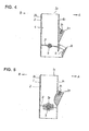
- Fig. 4 is a vertical cross sectional view along a line G-G in Fig. 1
- Fig. 5 is a vertical cross sectional view along a line H-H in Fig. 1.
- Reference numeral (1) denotes a first throttle body in which a first intake path (2) is provided through in a vertical direction.
- a first injection valve inclined end surface (1e) is formed in one side outer surface (1b) of the first throttle body (1) , whereby a first injection valve support hole (1f) is provided through in an oblique direction toward a center of the first intake path (2).
- a first supply body inclined end surface (1g) is formed in the one side outer surface (1b) of the first throttle body (1) at an upper position than the first injection valve inclined end surface (1e), whereby a female screw hole (1h) is provided in an oblique direction toward the center of the first intake path (2).
- Reference numeral (3) denotes a second throttle body in which a second intake path (4) is provided through in a vertical direction.
- the first intake path (2) and the second intake path (4) are arranged in adjacent in a horizontal direction in Fig. 1, and longitudinal axial lines of the respective intake paths (2) and (4) are arranged in parallel.
- a first supply body inclined end surface (1j) is formed in one side outer surface (3b) of the second throttle body (3), whereby a female screw hole (1h) is provided in an oblique direction toward a center of the second intake path (4).
- the first supply body inclined end surface (1g) , the first injection valve inclined end surface (1e) and the first supply body inclined end surface (1j) are inclined so as to lower the left side thereof in Figs. 2 and 3, and are formed so as to have the same angle of incline.
- first supply body inclined end surfaces (1g) and (1j) are formed at the same position in a vertical direction and a horizontal direction in Figs. 2 and 3.
- a second injection valve inclined end surface (1k) is formed in the other side outer surface (3a) of the second throttle body (3), whereby a second injection valve support hole (11) is provided in an oblique direction toward the center of the second intake path (4).
- a second supply body inclined end surface (1m) is formed in the other side outer surface (3a) of the second throttle body (3) at an upper position than the second injection valve inclined end surface (1k), whereby the female screw hole (1h) is provided in an oblique direction toward the center of the second intake path (4).
- a second supply body inclined end surface (1p) is formed in the other side outer surface (1n) of the first throttle body (1) , whereby the female screw hole (1h) is provided in an oblique direction toward the center of the first intake path (2).
- the second supply body inclined end surface (1m), the second injection valve inclined end surface (1k) and the second supply body inclined end surface (1p) are inclined so as to lower the right side thereof in Figs. 4 and 5, and are formed so as to have the same angle of incline.
- the second supply body inclined end surfaces (1m) and (1p) are formed at the same position in a vertical direction and a horizontal direction in Figs. 4 and 5.
- Reference numeral (5) denotes a throttle valve shaft cutting across the first intake path (2) and the second intake path (4) in the horizontal direction in Fig. 1 and constituted by one shaft rotatably supported to the first throttle body (1) and the second throttle body (3), a throttle drum (6) operated by a driver is attached to a left end (5c) of the throttle valve shaft (5) protruding to a left side from the second throttle body (3), and an angle sensor (7) detecting an angle of rotation of the throttle valve shaft (5) is attached to a right end (5d) of the throttle valve shaft (5) protruding to a right side from the first throttle body (1).
- a first throttle valve (8) is attached to the throttle valve shaft (5) arranged within the first intake path (2)
- a second throttle valve (9) is attached to the throttle valve shaft (5) arranged within the second intake path (4)
- the first intake path (2) and the second intake path (4) are controlled so as to be synchronously opened and closed by the first throttle valve (8) and the second throttle valve (9).
- first throttle body (1) and the second throttle body (3) are connected by a connecting boss including a bearing boss (5e) surrounding an outer periphery of the throttle valve shaft (5).
- a valve opening wire and a valve closing wire are engaged to the throttle drum (6) in the same manner as the conventional one.
- the first intake path (2) extending in the first throttle body (1) and the second intake path (4) extending in the second throttle body (3) are arranged in adjacent in the horizontal direction, longitudinal axial lines of the respective intake paths (2) and (4) are arranged in parallel, and the throttle valve shaft constituted by one shaft is arranged so as to cut across the centers of the first and second intake paths (2) and (4) in the horizontal direction.
- first supply body inclined end surface (1g) and the first injection valve inclined end surface (1e) provided with the first injection valve support hole (1f) are formed in one side B of the first throttle body (1) , and the second supply body inclined end surface (1p) is formed in the other side A.
- first supply body inclined end surface (1j) is formed in one side B of the second throttle body (3), and the second supply body inclined end surface (1m) and the second injection valve inclined end surface (1k) provided with the second injection valve support hole (11) are formed in the other side A.
- a first fuel supply body (10) and a second fuel supply body (11) are prepared as the fuel supply body.
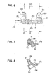
- Fig. 6 is a plan view of an upper portion of the first fuel supply body
- Fig. 7 is a vertical cross sectional view along a line K-K in Fig. 6
- fig. 8 is a vertical cross sectional view along a line L-L in Fig. 6
- Fig. 9 is a vertical cross sectional view along a line M-M in Fig. 6.
- the first fuel supply body (10) is structured such that a first fuel distribution path (10a) extending in a horizontal direction in Fig. 6 is provided in an inner portion thereof, and a fuel inflow path (10b) open toward a left side is formed in a left end thereof.
- a first attaching collar portion (10c) extending toward a right side in Fig. 8 is formed near a right end of the first fuel supply body (10), a first attaching hole (10d) is provided in a leading end portion thereof, and a first injection valve insertion hole (10f) communicating with the first fuel distribution path (10a) is formed toward an upper side in a lower end surface (10e) of the first attaching collar portion (10c).
- a second attaching collar portion (10g) extending toward a right side in Fig. 7 is formed near a left end of the first fuel supply body (10), a second attaching hole (10h) is provided in a leading end portion thereof, and a female screw hole (10j) is formed toward an upper side in a lower center portion thereof.
- both of the lower end surface (10e) of the first attaching collar portion (10c) and the lower end surface (10k) of the second attaching collar portion (10g) are formed as the inclined surface, and are formed so as to lower the left side thereof in Figs. 7 and 8 and at the same angle of incline.
- the angle of incline is equal to the angle of incline of the first supply body inclined end surface (1g) of the first throttle body (1), and the first supply body inclined end surface (1j) of the second throttle body (3).
- a first communicating joint insertion hole (10m) which communicates with the first fuel distribution path (10a) in an upper side and is open toward a lower end (101) is formed between the first attaching collar portion (10c) and the second attaching collar portion (10g).
- Fig. 10 is a plan view of an upper portion of a second fuel supply body
- Fig. 11 is a vertical cross sectional view along a line P-P in Fig. 10
- Fig. 12 is a vertical cross sectional view along a line N-N in Fig. 10
- Fig. 13 is a vertical cross sectional view along a line Q-Q in Fig. 10.
- the second fuel supply body (11) is structured such that a second fuel distribution path (11a) extending in a horizontal direction in Fig. 10 is provided in an inner portion thereof, and a right end thereof is open to a right side with an opening portion (11b) .
- a first attaching collar portion (11c) extending toward a left side in Fig. 12 is formed near a left end of the second fuel supply body (11), a first attaching hole (11d) is provided in a leading end portion thereof, and a second injection valve insertion hole (11f) communicating with the second fuel distribution path (11a) is formed toward an upper side in a lower end surface (11e) of the first attaching collar portion (11c).
- a second attaching collar portion (11g) extending toward a left side in Fig. 11 is formed near a right end of the second fuel supply body (11), a second attaching hole (11h) is provided in a leading end portion thereof, and a female screw hole (11j) is formed toward an upper side in a lower center portion thereof.
- both of the lower end surface (11e) of the first attaching collar portion (11c) and the lower end surface (11k) of the second attaching collar portion (11g) are formed as the inclined surface, and are formed so as to lower the right side thereof in Figs. 11 and 12 and at the same angle of incline.
- the angle of incline is equal to the angle of incline of the second supply body inclined end surface (1p) of the first throttle body (1), and the second supply body inclined end surface (1m) of the second throttle body (3).
- a second communicating joint insertion hole (11m) which communicates with the second fuel distribution path (11a) in an upper side and is open toward a lower end (111) is formed between the first attaching collar portion (11c) and the second attaching collar portion (11g).
- Fig. 14 is a plan view of an upper portion of the communicating joint
- Fig. 15 is a vertical cross sectional view along a line R-R in Fig. 14.
- a first communicating joint (12) has a first attaching collar portion (12a), a first insertion protruding portion (12b) is formed so as to protrude toward an upper side from a right end of the first attaching collar portion (12a) , a first joint portion (12c) extending toward a side portion (an upper side in Fig. 14) is formed in a lower side of the first insertion protruding portion (12b), and a first flow path (12f) is provided toward an end portion (12e) of the first joint portion (12c) from an end portion (12d) of the first insertion protruding portion (12b) .
- an attaching hole (12g) is provided in a left end of the first attaching collar portion (12a).
- a second communicating joint (13) which is absolutely the same as the first communicating joint (12) is prepared, structures and reference numerals of respective portions of the first communicating joint (12) are used to those of the second communicating joint (13) by changing the word of first and the numeral of (12) to second and (13) respectively, in order to make a description at a time of being assembled easy.
- a second attaching collar portion, a second insertion protruding portion and a second flow path of the second communicating joint (13) are called as a second attaching collar portion (13a), a second insertion protruding portion (13b) and a second flow path (13f).
- the fuel supply apparatus is formed by assembling the structures mentioned above in accordance with the following manner.
- the first fuel supply body (10) is assembled with the first and second throttle bodies (1) and (3) in accordance with the following way.
- the lower end surface (10e) of the first attaching collar portion (10c) of the first fuel supply body (10) is arranged in a contact manner on the first supply body inclined end surface (1g) of the first throttle body (1), the lower portion (Ja) of the first fuel injection valve (J1) is arranged so as to be inserted into the first injection valve support hole (1f), and the upper portion (Jb) of the first fuel injection valve (J1) is arranged so as to be inserted into the first injection valve insertion hole (10f) of the first fuel supply body (10).
- a screw (14) is inserted into the first attaching hole (10d) of the first attaching collar portion (10c) and the screw (14) is screwed toward the female screw hole (1h) open to the first supply body inclined end surface (1g) .
- the screw (14) is inserted into the second attaching hole (10h) of the second attaching collar portion (10g) and the screw (14) is screwed toward the female screw hole (1h) open to the second supply body inclined end surface (1j) .
- the right end of the first fuel supply body (10) is fixed to the one side outer surface (1b) of the first throttle body (1) via the first attaching collar portion (10c), and the left end of the first fuel supply body (10) is fixed to the one side outer surface (3b) of the second throttle body (3) via the second attaching collar portion (10g), whereby the first fuel supply body (10) is arranged so as to be firmly fixed to the one side B of the throttle body.
- the upper portion (Jb) of the first fuel injection valve (J1) is inserted into and supported by the first injection valve insertion hole (10f) of the first fuel supply body (10), the lower portion (Ja)is inserted into and supported by the first injection valve support hole (1f) of the first throttle body (1) , and the first fuel injection valve (J1) is pinched by the first throttle body (1) and the first fuel supply body (10).
- the second fuel supply body (11) is assembled with the first and second throttle bodies (1) and (3) in accordance with the following way.
- the lower end surface (11e) of the first attaching collar portion (11c) of the second fuel supply body (11) is arranged in a contact manner on the second supply body inclined end surface (1m) of the second throttle body (3), the lower portion (Ja) of the second fuel injection valve (J2) is arranged so as to be inserted into the second injection valve support hole (11), and the upper portion (Jb) of the second fuel injection valve (J2) is arranged so as to be inserted into the second injection valve insertion hole (11f) of the second fuel supply body (11).
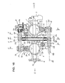
- This state is disclosed in Fig. 19 corresponding to a cross section along a line U-U in Fig. 16).
- the lower end surface (11k) of the second attaching collar portion (11g) of the second fuel supply body (11) is arranged on the second supply body inclined end surface (1p) of the first throttle body (1).(This state is disclosed in Fig. 20 corresponding to a cross section along a line V-V in Fig. 16).
- the screw (14) is inserted into the first attaching hole (11d) of the first attaching collar portion (11c) and the screw (14) is screwed toward the female screw hole (1h) open to the second supply body inclined end surface (1m).
- the screw (14) is inserted into the second attaching hole (11h) of the second attaching collar portion (11g) and the screw (14) is screwed toward the female screw hole (1h) open to the second supply body inclined end surface (1p) .
- the left end of the second fuel supply body (11) is fixed to the other side outer surface (3a) of the second throttle body (3) via the first attaching collar portion (11c), and the right end of the second fuel supply body (11) is fixed to the other side outer surface (1n) of the first throttle body (1) via the second attaching collar portion (11g) , whereby the second fuel supply body (11) is arranged so as to be firmly fixed to the other side A of the throttle body.
- the upper portion (Jb) of the second fuel injection valve (J2) is inserted into and supported by the second injection valve insertion hole (11f) of the second fuel supply body (11), the lower portion (Ja) is inserted into and supported by the second injection valve support hole (11) of the second throttle body (3), and the second fuel injection valve (J2) is pinched by the second throttle body (3) and the first fuel supply body (11).
- the first insertion protruding portion (12b) of the first communicating joint (12) is inserted into the first communicating joint insertion hole (10m) of the first fuel supply body (10), the screw (14) is inserted into the attaching hole (12g) , and the screw (14) is screwed toward the female screw hole (10j) open to the lower side of the first fuel supply body (10).
- the first communicating joint (12) is firmly fixed to the lower surface of the first fuel supply body (10), and the first insertion protruding portion (12b) is arranged so as to be fixed within the first communicating joint insertion hole (10m).
- the second insertion protruding portion (13b) of the second communicating joint (13) is inserted into the second communicating joint insertion hole (11m) of the second fuel supply body (11), the screw (14) is inserted into the attaching hole (13g) , and the screw (14) is screwed toward the female screw hole (11j) open to the lower side of the second fuel supply body (11).
- the second communicating joint (13) is firmly fixed to the lower surface of the second fuel supply body (11), and the second insertion protruding portion (23b) is arranged so as to be fixed within the second communicating joint insertion hole (11m).
- first joint portion (12c) of the first communicating joint (12) and the second joint portion (13c) of the second communicating joint (13) are communicated by a fuel communicating pipe (16).
- a pressure regulator (R) is arranged in the opening portion (11b) of the second fuel supply body (11) , and a fuel chamber (Ra) of the pressure regulator (R) is connected to the second fuel distribution path (11a) of the second fuel supply body (11) via a fuel inlet (Rb).
- the pressure of the fuel within the fuel tank (not shown) is increased by the fuel pump, and the fuel having the increased pressure is supplied into the first fuel distribution path (10a) of the first fuel supply body (10) via a fuel pipe (89) and the fuel inflow path (10b).
- a part of the fuel existing within the first fuel distribution path (10a) is supplied toward the upper portion (Jb) of the first fuel injection valve (J1) from the first injection valve inserting hole (10f) , and is injected and supplied toward a center direction within the first intake path (2) of the first throttle body (1) via the injection hole (Jc) of the lower portion (Ja).
- the other portion of the fuel existing within the first fuel distribution path (10a) is supplied to the first flow path (12f) of the first communicating joint (12) from the first communicating joint insertion hole (10m), and the fuel is supplied into the second fuel distribution path (11a) of the second fuel supply body (11) via the first joint portion (12c) , the fuel communicating pipe (16), the second fuel joint (13c) of the second communicating joint (13), the second flow path (13f) and the second communicating joint insertion hole (11m) of the second fuel supply body (11).
- a part of the fuel within the second fuel distribution path (11a) is supplied toward the upper portion (Jb) of the second fuel injection valve (J2) from the second injection valve insertion hole (11f), and is injected and supplied in the center direction within the second intake path (4) of the second throttle body (3) via the injection hole (Jc) of the lower portion (Ja).
- the pressure regulator (R) is arranged in the opening portion (11b) of the second fuel distribution path (11a) of the second fuel supply body (11), the other portion of the fuel within the second fuel distribution path (11a) is introduced into the fuel chamber (Ra) via the opening portion (11b) and the fuel inlet (Rb), whereby it is possible to regulate the pressure of the fuel flowing within the first and second fuel distribution paths (10a) and (11a) to a desired fixed pressure. (Since the pressure regulator (R) is known, a description of the fuel pressure regulating operation will be omitted.)
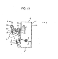
- the fuel supply apparatus in accordance with the present invention is characterized in that the fuel communicating pipe (16) for communicating of the first fuel distribution path (10a) of the first fuel supply body (10) arranged in the one side outer surfaces (1b) and (3b) of the first and second throttle bodies (1) and (3) and the second fuel distribution path (11a) of the second fuel supply body (11) arranged in the other side outer surfaces (1a) and (3a) of the first and second throttle bodies (1) and (3) is connected via an adjacent space (shown in Fig. 16) formed in a region (Y) between opposing side surfaces of the left side outer surface (1y) of the first throttle body (1) and the right side outer surface (3y) of the second throttle body (3) in the horizontal direction, and in a region (X) (shown in Fig. 21) between the upper side of the throttle valve shaft (5) and the upper ends (1x) and (3x) of the respective throttle bodies (1) and (3) in the vertical direction thereof.
- the first fuel distribution path (10a) can communicate with the second fuel distribution path (11a) at a shortest distance by the fuel communicating pipe (16), and it is possible to make the pipe length of the fuel communicating pipe (16) short.
- the fuel communicating pipe (16) it is possible to inhibit the fuel communicating pipe (16) from being heated up due to the influence of the temperature of the ambient atmosphere of the engine, and it is possible to prevent the fuel from being evaporated within the fuel communicating pipe (16) , thereby preventing the vapor from being generated.
- the fuel flow from the first fuel distribution path (10a) toward the second fuel distribution path (11a) is not interrupted by the vapor, it is possible to always maintain a smooth fuel flow, and it is possible to always supply the stable fuel continuously and accurately from the second fuel injection valve (J2).
- the support member is not necessarily provided for preventing the fuel communicating pipe (16) from deflecting and wobbling.
- the structure is preferably applied to the two-wheel vehicle in which the fuel supply apparatus is arranged so as to be directly exposed to the exterior.
- the fuel communicating pipe (16) is arranged within the adjacent space of the first and second throttle bodies (1) and (3), the fuel communicating pipe (16) does not interfere with the other members (for example, a frame, a seat or the like) than the fuel supply apparatus, and it is possible to largely improve a layout property of the fuel communicating pipe (16). Further, since the fuel communicating pipe (16) is arranged in the inner portion of the fuel supply apparatus, it is possible to arrange an outer appearance neat at a time of applying to the two-wheel vehicle.
- the first fuel supply body (10) is fixed to the first throttle body (1) via the first attaching hole (10d) of the first attaching collar portion (10c), and fixed to the second throttle body (3) via the second attaching hole (10h) of the second attaching collar portion (10g) , the first fuel supply body (10) can be firmly fixed to the throttle body.
- the second fuel supply body (11) is fixed to the second throttle body (3) via the first attaching hole (11d) of the first attaching collar portion (11c) , and fixed to the first throttle body (1) via the second attaching hole (11h) of the second attaching collar portion (11g), the second fuel supply body (11) can be firmly fixed to the throttle body.
- the communicating joints (12) and (13) can be formed by the parts having small shapes, and the fuel communicating pipe (16) can be formed by the short linear pipe.
- first and second communicating joints (12) and (13) in which the fuel communicating pipe (16) is attached within the adjacent space of the throttle bodies (1) and (3) after previously assembling the first and second fuel supply bodies (10) and (11) with the respective throttle bodies (1) and (3), and it is possible to thereafter insert and fix the second communicating joint (13) to the second communicating joint insertion hole (11m) of the second fuel supply body (11), and insert and fix the first communicating joint (12) to the first communicating joint insertion hole (10m) of the first fuel supply body (10).
- the pressure regulator (R) is arranged in the opening portion (11b) of the second fuel supply body (11), the member for holding the pressure regulator (R) is not required, so that it is possible to reduce the number of the parts. Further, since the second fuel supply body (11) is firmly fixed to the throttle bodies (1) and (3) with the first attaching collar portion (11c) and the second attaching collar portion (11g), it is possible to securely attach the pressure regulator (R).
- the opening portion (11b) may be closed by the closing plug.
- the lower end surface (11e) of the first attaching collar portion (10c) in the first fuel supply body (10) and the lower end surface (10k) of the second attaching collar portion (10g) are formed at the same angle of incline, it is possible to accurately arrange the first fuel supply body (10) in the horizontal state with respect to the throttle bodies (1) and (3), whereby it is possible to accurately arrange the upper portion (Jb) of the first fuel injection valve (J1) within the first injection valve insertion hole (10f) of the first fuel supply body (10) without generating the fuel leak.
- the second fuel supply body (11) it is possible to accurately arrange the upper portion (Jb) of the second fuel injection valve (J2) within the second injection valve insertion hole (11f) of the second fuel supply body (11) without generating the fuel leak in the same manner as mentioned above.
- a first sub throttle valve (20) is arranged in the first intake path (2) in the upstream side of the first throttle valve (8), and a second sub throttle valve (21) is arranged in the second intake path (4) in the upstream side of the second throttle valve (9) .
- These first sub throttle valve (20) and the second sub throttle valve (21) are attached to a second throttle valve shaft (22) formed by one shaft cutting across from the first intake path (2) toward the second intake path (4).
- the first sub throttle valve (20) opens and closes the first intake path (2) in the upstream side of the first throttle valve (8)
- the second sub throttle valve (21) opens and closes the second intake path (4)in the upstream side of the second throttle valve (9).
- the fuel communicating pipe communicates via an adjacent space formed between the upper side of the throttle valve shaft (5) and the lower side of the second throttle valve shaft (22) in the vertical direction, between the opposing side surfaces of the left side outer surface (1y) of the first throttle body (1) and the right side outer surface (3y) of the second throttle body (3) in the horizontal direction.
- first communicating joint (12) and the second communicating joint (13) to which the end portions of the fuel communicating pipe (16) are inserted may be previously formed integrally in the first fuel supply body (10) and the second fuel supply body (11).
- the most characteristic part of the present invention is that the fuel communicating pipe connecting the first fuel supply body and the second fuel supply body by the flow path is connected via the adjacent space formed between the upper side of the throttle valve shaft constituted by one shaft and the upper end of the throttle body in the vertical direction between the opposing side surfaces of both the throttle bodies in the horizontal direction, in the fuel supply apparatus in which the throttle bodies are arranged in adjacent in the horizontal direction, the first fuel injection valve including the first fuel supply body is arranged in the one side of the throttle bodies, and the second fuel injection valve including the second fuel supply body is arranged in the other side of the throttle bodies.
Landscapes
- Engineering & Computer Science (AREA)
- Chemical & Material Sciences (AREA)
- Combustion & Propulsion (AREA)
- Mechanical Engineering (AREA)
- General Engineering & Computer Science (AREA)
- Fuel-Injection Apparatus (AREA)
- Control Of Throttle Valves Provided In The Intake System Or In The Exhaust System (AREA)
Abstract
Description
wherein the first fuel injection valve is pinched by a first fuel supply body provided with a fuel inflow path and a first fuel distribution path, and by the first throttle body, and the second fuel injection valve is pinched by a second fuel supply body provided with a second fuel distribution path and the second throttle body, and
wherein a fuel communicating pipe for communicating of the first fuel distribution path of the first fuel supply body and the second fuel distribution path of the second fuel supply body communicates via an adjacent space formed between opposing side surfaces of a left side outer surface of the first throttle body and a right side outer surface of the second throttle body in a horizontal direction thereof, and between an upper side of the throttle valve shaft and an upper end of each of the throttle bodies in a vertical direction thereof.
wherein the second fuel supply body is formed in parallel to the throttle valve shaft, a second injection valve insertion hole for inserting an upper portion of the second fuel injection valve and communicating with the second fuel distribution path, and a first attaching collar portion provided with a first attaching hole are formed near a left end thereof, a second attaching collar portion provided with a second attaching hole is formed near a right end thereof, and a second communicating joint insertion hole communicating with the second fuel distribution path is formed between the first and second attaching collar portions,
wherein the first fuel supply body is screwed with the first throttle body via the first attaching hole of the first attaching collar portion and is screwed with the second throttle body via the second attaching hole of the second attaching collar portion, the second fuel supply body is screwed with the second throttle body via the first attaching hole of the first attaching collar portion and is screwed with the first throttle body via the second attaching hole of the second attaching collar portion, a first communicating joint is inserted to the first communicating joint insertion hole so as to be fixedly arranged in the first fuel supply body, and a second communicating joint is inserted to the second communicating joint insertion hole so as to be fixedly arranged in the second fuel supply body, and
wherein the first communicating joint and the second communicating joint communicate by a fuel communicating pipe.
wherein a lower end surface of the first attaching collar portion and a lower end surface of the second attaching collar portion formed in the second fuel supply body are formed at the same angle of incline in a cross section orthogonal to the second fuel distribution path.
wherein the first sub throttle valve and the second sub throttle valve are attached to a second throttle valve shaft constituted by one shaft cutting across to the second intake path from the first intake path, and
wherein the fuel communicating pipe communicates via an adjacent space formed between opposing side surfaces of a left side outer surface of the first throttle body and a right side outer surface of the second throttle body in a horizontal direction thereof and between an upper side of the throttle valve shaft and a lower side of the second throttle valve shaft in a vertical direction thereof.
Claims (5)
- A fuel supply apparatus comprising:wherein the throttle valve shaft (5) to which the first and second throttle valves (8, 9) are attached, is formed by one shaft and is arranged across toward the second intake path (4) from the first intake path (2), and a throttle drum (6) is fixedly arranged in a left end (5c) of the throttle valve shaft (5) protruding from a left side outer surface of the second throttle body (3),a first intake path extending through a first throttle body and a second intake path extending through a second throttle body, said first intake path and said second intake path being arranged in adjacent in a horizontal direction and arranged so as to be parallel in longitudinal axial lines of the respective intake paths;a first throttle valve and a second throttle valve opening and closing said first and second intake paths, said first and second throttle valves being attached to a throttle valve shaft which is coaxially arranged so as to cut across the respective intake paths; anda first fuel injection valve arranged in one side outer surface of the first throttle body in such a manner that a lower injection hole is inclined toward a center of the first intake path, and a second fuel injection valve arranged in the other side outer surface of the second throttle body in such a manner that a lower injection hole is inclined toward a center of the second intake path,
wherein said first fuel injection valve (J1) is pinched by a first fuel supply body (10) provided with a fuel inflow path (10b) and a first fuel distribution path (10a), and by the first throttle body (1), and the second fuel injection valve (J2) is pinched by a second fuel supply body (11) provided with a second fuel distribution path (11a) and the second throttle body (3), and
wherein a fuel communicating pipe (16) for communicating of the first fuel distribution path (10a) of said first fuel supply body (10) and the second fuel distribution path (11a) of the second fuel supply body (11) communicates via an adjacent space formed between opposing side surfaces of a left side outer surface (1y) of the first throttle body (1) and a right side outer surface (3y) of the second throttle body (3) in a horizontal direction thereof, and between an upper side of the throttle valve shaft (5) and an upper end (1x, 3x) of each of the throttle bodies (1, 3) in a vertical direction thereof. - A fuel supply apparatus as claimed in claim 1,
wherein said first fuel supply body is formed in parallel to the throttle valve shaft (5), a first injection valve insertion hole (10f) for inserting an upper portion (Jb) of the first fuel injection valve (J1) and communicating with the first fuel distribution path (10a), and a first attaching collar portion (10c) provided with a first attaching hole (10d) are formed near a right end thereof, a second attaching collar portion (10g) provided with a second attaching hole (10h) is formed near a left end thereof, and a first communicating joint insertion hole (10m) communicating with the first fuel distribution path (10a) is formed between the first and second attaching collar portions (10c, 10g).
wherein said second fuel supply body (11) is formed in parallel to the throttle valve shaft (5), a second injection valve insertion hole (11f) for inserting an upper portion (Jb) of the second fuel injection valve (J2) and communicating with the second fuel distribution path (11a), and a first attaching collar portion (11c) provided with a first attaching hole (11d) are formed near a left end thereof, a second attaching collar portion (11g) provided with a second attaching hole (11h) is formed near a right end thereof, and a second communicating joint insertion hole (11m) communicating with the second fuel distribution path (11a) is formed between the first and second attaching collar portions (11c, 11g),
wherein said first fuel supply body (10) is screwed with the first throttle body (1) via the first attaching hole (10d) of the first attaching collar portion. (10c) and is screwed with the second throttle body (3) via the second attaching hole (10h) of the second attaching collar portion (10g), the second fuel supply body (11) is screwed with the second throttle body (3) via the first attaching hole (11d) of the first attaching collar portion (11c) and is screwed with the first throttle body (1) via the second attaching hole (11h) of the second attaching collar portion (11g), a first communicating joint (12) is inserted to the first communicating joint insertion hole (10m) so as to be fixedly arranged in the first fuel supply body (10), and a second communicating joint (13) is inserted to the second communicating joint insertion hole (11m) so as to be fixedly arranged in the second fuel supply body (11), and
wherein said first communicating joint and the second communicating joint (13) communicate by a fuel communicating pipe (16). - A fuel supply apparatus as claimed in claim 1,
wherein any one of a right end and a left end of the second fuel distribution path (11a) of said second fuel supply body is open with an opening portion (11b), and a pressure regulator (R) is arranged in said opening portion. - A fuel supply apparatus as claimed in claim 2,
wherein a lower end surface (10e) of the first attaching collar portion (10e) and a lower end surface (10k) of the second attaching collar portion (10g) formed in said first fuel supply body are formed at the same angle of incline in a cross section orthogonal to the first fuel distribution path (10a), and
wherein a lower end surface (11e) of the first attaching collar portion (11c) and a lower end surface (11k) of the second attaching collar portion (11g) formed in the second fuel supply body (11) are formed at the same angle of incline in a cross section orthogonal to the second fuel distribution path (11a). - A fuel supply apparatus as claimed in claim 1,
wherein a first sub throttle valve (20) and a second sub throttle valve (21) are arranged in first and second intake paths (2, 4) in an upstream side of the first and second throttle valves (8, 9) of said first and second throttle bodies,
wherein said first sub throttle valve (20) and the second sub throttle valve (21) are attached to a second throttle valve shaft (22) constituted by one shaft cutting across to the second intake path (9) from the first intake path (8), and
wherein said fuel communicating pipe communicates via an adjacent space formed between opposing side surfaces of a left side outer surface (1y) of the first throttle body (1) and a right side outer surface (3y) of the second throttle body (3) in a horizontal direction thereof and between an upper side of the throttle valve shaft (5) and a lower side of the second throttle valve shaft (22) in a vertical direction thereof.
Applications Claiming Priority (2)
| Application Number | Priority Date | Filing Date | Title |
|---|---|---|---|
| JP2004121082A JP4074942B2 (en) | 2004-04-16 | 2004-04-16 | Fuel supply device |
| JP2004121082 | 2004-04-16 |
Publications (2)
| Publication Number | Publication Date |
|---|---|
| EP1586764A1 true EP1586764A1 (en) | 2005-10-19 |
| EP1586764B1 EP1586764B1 (en) | 2010-06-30 |
Family
ID=34938160
Family Applications (1)
| Application Number | Title | Priority Date | Filing Date |
|---|---|---|---|
| EP05075851A Expired - Lifetime EP1586764B1 (en) | 2004-04-16 | 2005-04-13 | Fuel supply apparatus |
Country Status (4)
| Country | Link |
|---|---|
| US (1) | US7028665B2 (en) |
| EP (1) | EP1586764B1 (en) |
| JP (1) | JP4074942B2 (en) |
| DE (2) | DE602005022010D1 (en) |
Cited By (2)
| Publication number | Priority date | Publication date | Assignee | Title |
|---|---|---|---|---|
| EP1884658A3 (en) * | 2006-08-03 | 2009-04-29 | Keihin Corporation | Fuel distribution pipe structure in multiple throttle body |
| EP1978235A3 (en) * | 2007-04-06 | 2010-06-02 | Keihin Corporation | Throttle body in fuel injection apparatus |
Families Citing this family (8)
| Publication number | Priority date | Publication date | Assignee | Title |
|---|---|---|---|---|
| JP4305339B2 (en) * | 2004-09-08 | 2009-07-29 | 日産自動車株式会社 | Mounting structure of fuel injection device in internal combustion engine |
| JP4511975B2 (en) * | 2005-03-02 | 2010-07-28 | 株式会社ケーヒン | Fuel supply pipe structure in a throttle body with two fuel injection valves |
| JP4334493B2 (en) * | 2005-03-17 | 2009-09-30 | 株式会社ケーヒン | Fuel supply pipe structure in a multiple throttle body with two fuel injection valves |
| JP2006283585A (en) * | 2005-03-31 | 2006-10-19 | Yamaha Motor Co Ltd | Throttle body |
| JP2009085111A (en) * | 2007-09-29 | 2009-04-23 | Honda Motor Co Ltd | Fuel supply structure for V-type multi-cylinder engine |
| JP4964815B2 (en) * | 2008-03-28 | 2012-07-04 | 本田技研工業株式会社 | Intake air amount control device for V-type internal combustion engine |
| JP6256918B2 (en) * | 2014-09-30 | 2018-01-10 | 本田技研工業株式会社 | Injector assembly |
| AU2018378313B2 (en) * | 2017-12-04 | 2025-01-23 | Holley Performance Products, Inc. | Electronic fuel injection throttle body assembly |
Citations (4)
| Publication number | Priority date | Publication date | Assignee | Title |
|---|---|---|---|---|
| US4964381A (en) * | 1988-07-29 | 1990-10-23 | Honda Giken Kogyo Kabushiki Kaisha | Fuel injection features of a two-cycle engine for motorcycles |
| US5101792A (en) * | 1989-10-20 | 1992-04-07 | Dr. Ing. H.C.F. Porsche, Ag | Internal combustion engine fuel distributor housing |
| US5197436A (en) * | 1989-03-31 | 1993-03-30 | Yamaha Hatsudoki Kabushiki Kaisha | Fuel delivery system for V-type engine |
| US5577477A (en) * | 1994-07-15 | 1996-11-26 | Sanshin Kogyo Kabushiki Kaisha | Fuel supply for injected engine |
Family Cites Families (4)
| Publication number | Priority date | Publication date | Assignee | Title |
|---|---|---|---|---|
| JPS6056908B2 (en) * | 1978-11-06 | 1985-12-12 | 株式会社日立製作所 | Fuel control device for fuel injection system |
| JP2000145581A (en) * | 1998-11-13 | 2000-05-26 | Sanshin Ind Co Ltd | Direct injection engine |
| JP3934834B2 (en) | 1999-10-19 | 2007-06-20 | 株式会社ケーヒン | Engine intake air amount control device |
| JP4463488B2 (en) * | 2003-03-27 | 2010-05-19 | 本田技研工業株式会社 | Throttle body |
-
2004
- 2004-04-16 JP JP2004121082A patent/JP4074942B2/en not_active Expired - Fee Related
-
2005
- 2005-04-13 US US11/104,846 patent/US7028665B2/en not_active Expired - Fee Related
- 2005-04-13 EP EP05075851A patent/EP1586764B1/en not_active Expired - Lifetime
- 2005-04-13 DE DE602005022010T patent/DE602005022010D1/en not_active Expired - Lifetime
- 2005-04-13 DE DE05075851T patent/DE05075851T1/en active Pending
Patent Citations (4)
| Publication number | Priority date | Publication date | Assignee | Title |
|---|---|---|---|---|
| US4964381A (en) * | 1988-07-29 | 1990-10-23 | Honda Giken Kogyo Kabushiki Kaisha | Fuel injection features of a two-cycle engine for motorcycles |
| US5197436A (en) * | 1989-03-31 | 1993-03-30 | Yamaha Hatsudoki Kabushiki Kaisha | Fuel delivery system for V-type engine |
| US5101792A (en) * | 1989-10-20 | 1992-04-07 | Dr. Ing. H.C.F. Porsche, Ag | Internal combustion engine fuel distributor housing |
| US5577477A (en) * | 1994-07-15 | 1996-11-26 | Sanshin Kogyo Kabushiki Kaisha | Fuel supply for injected engine |
Cited By (2)
| Publication number | Priority date | Publication date | Assignee | Title |
|---|---|---|---|---|
| EP1884658A3 (en) * | 2006-08-03 | 2009-04-29 | Keihin Corporation | Fuel distribution pipe structure in multiple throttle body |
| EP1978235A3 (en) * | 2007-04-06 | 2010-06-02 | Keihin Corporation | Throttle body in fuel injection apparatus |
Also Published As
| Publication number | Publication date |
|---|---|
| JP4074942B2 (en) | 2008-04-16 |
| DE602005022010D1 (en) | 2010-08-12 |
| EP1586764B1 (en) | 2010-06-30 |
| US20050229902A1 (en) | 2005-10-20 |
| DE05075851T1 (en) | 2006-06-22 |
| JP2005299613A (en) | 2005-10-27 |
| US7028665B2 (en) | 2006-04-18 |
Similar Documents
| Publication | Publication Date | Title |
|---|---|---|
| EP3070323B1 (en) | Arrangement for retaining a fuel injector to a fuel rail socket | |
| US11225916B2 (en) | Electronic fuel injection throttle body assembly | |
| US12215659B2 (en) | Electronic fuel injection throttle body assembly | |
| EP0867608B1 (en) | Air intake apparatus for a four-cycle internal combustion engine | |
| EP1586764B1 (en) | Fuel supply apparatus | |
| US6526933B2 (en) | Multi-cylinder internal combustion engine | |
| US7198032B2 (en) | Structure of fuel supply pipe in throttle body comprising two fuel injection valves | |
| US6334430B1 (en) | Intake air amount control system for engine | |
| US10731572B2 (en) | Intake control apparatus | |
| HK1080534A (en) | Fuel supply apparatus | |
| US9334809B2 (en) | Throttle body structure | |
| JPH11303702A (en) | Throttle body for fuel injection system for motorcycles | |
| JP4896154B2 (en) | Supply air distribution device for internal combustion engines | |
| JP7621836B2 (en) | Intake system for multi-cylinder engine and fuel delivery pipe for intake system | |
| JP3303619B2 (en) | Fuel supply device for internal combustion engine | |
| JP6817773B2 (en) | Fuel injection device | |
| JP2760589B2 (en) | Air-fuel ratio control device for V-type internal combustion engine | |
| US8336519B2 (en) | Intake system of engine | |
| JP4794493B2 (en) | Throttle body in fuel injector | |
| EP1801412B1 (en) | Fuel supply pipe structure in two fuel injection valve type throttle body | |
| JPH086655B2 (en) | Mixture supply device for multi-cylinder internal combustion engine | |
| JP2003206822A (en) | Fuel supply device | |
| JPH07167021A (en) | Fuel injection system | |
| JP2003106246A (en) | Fuel injection device for two-cylinder engine | |
| JPH0385335A (en) | Mixture supply device for multi-cylinder internal combustion engine |
Legal Events
| Date | Code | Title | Description |
|---|---|---|---|
| PUAI | Public reference made under article 153(3) epc to a published international application that has entered the european phase |
Free format text: ORIGINAL CODE: 0009012 |
|
| AK | Designated contracting states |
Kind code of ref document: A1 Designated state(s): AT BE BG CH CY CZ DE DK EE ES FI FR GB GR HU IE IS IT LI LT LU MC NL PL PT RO SE SI SK TR |
|
| AX | Request for extension of the european patent |
Extension state: AL BA HR LV MK YU |
|
| 17P | Request for examination filed |
Effective date: 20051216 |
|
| EL | Fr: translation of claims filed | ||
| REG | Reference to a national code |
Ref country code: HK Ref legal event code: DE Ref document number: 1080534 Country of ref document: HK |
|
| DET | De: translation of patent claims | ||
| AKX | Designation fees paid |
Designated state(s): DE FR GB |
|
| GRAP | Despatch of communication of intention to grant a patent |
Free format text: ORIGINAL CODE: EPIDOSNIGR1 |
|
| GRAS | Grant fee paid |
Free format text: ORIGINAL CODE: EPIDOSNIGR3 |
|
| GRAA | (expected) grant |
Free format text: ORIGINAL CODE: 0009210 |
|
| AK | Designated contracting states |
Kind code of ref document: B1 Designated state(s): DE FR GB |
|
| REG | Reference to a national code |
Ref country code: GB Ref legal event code: FG4D |
|
| REF | Corresponds to: |
Ref document number: 602005022010 Country of ref document: DE Date of ref document: 20100812 Kind code of ref document: P |
|
| PLBE | No opposition filed within time limit |
Free format text: ORIGINAL CODE: 0009261 |
|
| STAA | Information on the status of an ep patent application or granted ep patent |
Free format text: STATUS: NO OPPOSITION FILED WITHIN TIME LIMIT |
|
| 26N | No opposition filed |
Effective date: 20110331 |
|
| REG | Reference to a national code |
Ref country code: DE Ref legal event code: R097 Ref document number: 602005022010 Country of ref document: DE Effective date: 20110330 |
|
| REG | Reference to a national code |
Ref country code: HK Ref legal event code: WD Ref document number: 1080534 Country of ref document: HK |
|
| REG | Reference to a national code |
Ref country code: FR Ref legal event code: PLFP Year of fee payment: 12 |
|
| PGFP | Annual fee paid to national office [announced via postgrant information from national office to epo] |
Ref country code: FR Payment date: 20160309 Year of fee payment: 12 |
|
| PGFP | Annual fee paid to national office [announced via postgrant information from national office to epo] |
Ref country code: DE Payment date: 20160405 Year of fee payment: 12 Ref country code: GB Payment date: 20160413 Year of fee payment: 12 |
|
| REG | Reference to a national code |
Ref country code: DE Ref legal event code: R119 Ref document number: 602005022010 Country of ref document: DE |
|
| GBPC | Gb: european patent ceased through non-payment of renewal fee |
Effective date: 20170413 |
|
| REG | Reference to a national code |
Ref country code: FR Ref legal event code: ST Effective date: 20171229 |
|
| PG25 | Lapsed in a contracting state [announced via postgrant information from national office to epo] |
Ref country code: FR Free format text: LAPSE BECAUSE OF NON-PAYMENT OF DUE FEES Effective date: 20170502 Ref country code: DE Free format text: LAPSE BECAUSE OF NON-PAYMENT OF DUE FEES Effective date: 20171103 |
|
| PG25 | Lapsed in a contracting state [announced via postgrant information from national office to epo] |
Ref country code: GB Free format text: LAPSE BECAUSE OF NON-PAYMENT OF DUE FEES Effective date: 20170413 |