EP1586735A2 - Framed shutter assembly with adjustable fins - Google Patents
Framed shutter assembly with adjustable fins Download PDFInfo
- Publication number
- EP1586735A2 EP1586735A2 EP05252136A EP05252136A EP1586735A2 EP 1586735 A2 EP1586735 A2 EP 1586735A2 EP 05252136 A EP05252136 A EP 05252136A EP 05252136 A EP05252136 A EP 05252136A EP 1586735 A2 EP1586735 A2 EP 1586735A2
- Authority
- EP
- European Patent Office
- Prior art keywords
- framed
- frame member
- shutter assembly
- assembly according
- horizontal frame
- Prior art date
- Legal status (The legal status is an assumption and is not a legal conclusion. Google has not performed a legal analysis and makes no representation as to the accuracy of the status listed.)
- Withdrawn
Links
- 230000008878 coupling Effects 0.000 claims description 13
- 238000010168 coupling process Methods 0.000 claims description 13
- 238000005859 coupling reaction Methods 0.000 claims description 13
- 230000015572 biosynthetic process Effects 0.000 description 14
- 238000005755 formation reaction Methods 0.000 description 14
- 238000003780 insertion Methods 0.000 description 4
- 230000037431 insertion Effects 0.000 description 4
- 230000000712 assembly Effects 0.000 description 2
- 238000000429 assembly Methods 0.000 description 2
- 238000010276 construction Methods 0.000 description 2
- 230000014509 gene expression Effects 0.000 description 2
- 230000000717 retained effect Effects 0.000 description 2
- 239000000725 suspension Substances 0.000 description 2
- 230000003466 anti-cipated effect Effects 0.000 description 1
- 238000001125 extrusion Methods 0.000 description 1
- 238000009432 framing Methods 0.000 description 1
- 238000012986 modification Methods 0.000 description 1
- 230000004048 modification Effects 0.000 description 1
- 239000007787 solid Substances 0.000 description 1
Images



Classifications
-
- E—FIXED CONSTRUCTIONS
- E06—DOORS, WINDOWS, SHUTTERS, OR ROLLER BLINDS IN GENERAL; LADDERS
- E06B—FIXED OR MOVABLE CLOSURES FOR OPENINGS IN BUILDINGS, VEHICLES, FENCES OR LIKE ENCLOSURES IN GENERAL, e.g. DOORS, WINDOWS, BLINDS, GATES
- E06B7/00—Special arrangements or measures in connection with doors or windows
- E06B7/02—Special arrangements or measures in connection with doors or windows for providing ventilation, e.g. through double windows; Arrangement of ventilation roses
- E06B7/08—Louvre doors, windows or grilles
- E06B7/084—Louvre doors, windows or grilles with rotatable lamellae
- E06B7/086—Louvre doors, windows or grilles with rotatable lamellae interconnected for concurrent movement
- E06B7/09—Louvre doors, windows or grilles with rotatable lamellae interconnected for concurrent movement mounted in movable wing, e.g. door
-
- E—FIXED CONSTRUCTIONS
- E06—DOORS, WINDOWS, SHUTTERS, OR ROLLER BLINDS IN GENERAL; LADDERS
- E06B—FIXED OR MOVABLE CLOSURES FOR OPENINGS IN BUILDINGS, VEHICLES, FENCES OR LIKE ENCLOSURES IN GENERAL, e.g. DOORS, WINDOWS, BLINDS, GATES
- E06B7/00—Special arrangements or measures in connection with doors or windows
- E06B7/02—Special arrangements or measures in connection with doors or windows for providing ventilation, e.g. through double windows; Arrangement of ventilation roses
- E06B7/08—Louvre doors, windows or grilles
- E06B7/084—Louvre doors, windows or grilles with rotatable lamellae
- E06B7/086—Louvre doors, windows or grilles with rotatable lamellae interconnected for concurrent movement
Definitions
- the present invention relates to a sliding shutter panel with adjustable fins. More in particular it relates to such a shutter panel that is slidably suspended from an overhead track.
- FIG. 1 there are illustrated in an exploded arrangement the principal elements of a framed shutter assembly according to the invention.
- the whole structure is slidably suspended from an overhead top rail 1, which will be attached to a building structure in a conventional manner.
- Retained in the top rail 1 are wheeled suspension runners 3 for translational movement along the length of the top rail 1.
- Suspended from the suspension runner 3 is a runner plate 5.
- This runner plate 5 will be fixedly retained in top horizintal frame member 7, which may be covered by cover 9 against the ingress of dirt.
- At the bottom of the assembly there is a horizontal bottom frame member 11, which preferably can be similar in shape to the horizontal top frame member 7.
- a bottom guide 13 for guiding the framed shutter assembly along a bottom rail 15.
- the horizontal bottom frame member 11 can be closed by a bottom cover 17.
- the bottom guide 13 will be explained in further detail in reference to Figures 13-15.
- the bottom cover 17 has apertures 17a, 17b to allow portions of the bottom guide 13 to protrude from the bottom frame member 11.
- the top cover 9 has an aperture 9a to allow a portion of the runner plate 5 to protrude from the top frame member 7.
- a vertical frame member 19 is provided to connect the top and bottom frame members 7, 11 which is accomplished by screws 21.
- the vertical frame member 19 is also preferably provided with a vertical side cover 23.
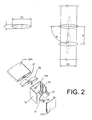
- FIG 2 in an exploded arrangement shows a first embodiment of fin 25A.
- the fin 25A is formed as an extrusion having a continuous cross section. Centrally of this cross section the fin 25A has cavity formation 27 for non-rotatably receiving a pivot pin 33.
- the open end of the fin 25A on both sides of the central cavity formation 27 is closed by a pair of similar end caps 29.
- the vertical frame member 19 is provided with an opening 19A in register with the central cavity formation 27 and that a rotatable disc 31 with a pivot pin 33 for engaging the central cavity formation 27 engages through the opening 19A.
- the disc 31 is only partly circular in shape for a purpose that will now be explained in reference to Figures 3 and 4.
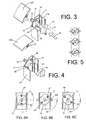
- FIG. 3 Shown in Figure 3 in dotted lines is a first position of the rotatable disc 31 before insertion into the vertical frame member 19.
- the flattened sides 35 and 37 of the disc 31 will pass ridges 39 and 41 on opposite sides of the vertical frame member 19 when the disc member 31 is moved in the direction of arrow 43.
- the pin 33 protrudes through the aperture 19A (not shown in Figure 3) and the fin 25A can be slid on with its central cavity formation 27 non-rotatably engaging the pin 33, so that it may only rotate together with the disc member 31.
- Rotation of the disc member 31 in the direction of arrow 45 will lock the disc member 31 behind the ridges 39 and 41.
- FIGs 6A through 6B show again the sequence of rotating the disc member 31 clockwise from the insertion position into the horizontal open position of the fin 25A (Fig 6B) and from the open horizontal position into the closed position (Fig 6C). It is further shown in Figs 2 through 6C, that the disc member 31 has first and second outwardly projecting pins 47 and 49. The purpose of the first and second pins 47 and 49 will now be explained in reference to Figures 7 and 8.
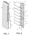
- FIG. 7 a partly assembled side portion of the framed shutter assembly is shown.
- a first coupling strip 51 is shown mounted and engaging a first pin 47 on each of a number of successive disc members 31. Since the number of fins 25A can vary substantially with the height of framed shutter assemblies coupling strips would normally need to be available for each possible number of fins. Since this is expensive and cumbersome the present invention proposes the use of a fixed length of coupling strip, while using a plurality of these in assembling framed shutter assemblies.
- an assembly lock 59 may be fitted in the manner of a coupling strip to a few of the second pins 49. Pivotal movement if the vanes will then be limited between two positions in which the assembly lock 59 abuts a confronting one of the coupling strips 51, 53, 55. This corresponds to the end positions as illustrated in Figures 6A and 6B.
- Figure 9 shows an alternative embodiment of fin 25B, such as a solid wooden fin.
- fin 25B such as a solid wooden fin.
- similar vertical frame members 19 are used which have equally spaced apertures 19A to receive a drive disk 65 with a central pivot pin 67 protruding through the aperture 19A.
- the pivot pin 67 is shaped to snap-fit into a central opening 69 or 71 of the respective end cap 61 or 63.
- the drive discs can be given a shape that allows their insertion between the ribs 39 and 41 in all angular positions and this can be a full circular shape as shown in Figure 9.
- the vertical frame member 19 can again be closed with a cover 23.
- FIG 10 shows the attachment of a runner 3 to the horizontal top frame member 7 using the runner plate 5.
- the top frame member 7 is provided with internal, partly circular formations 73 and 75 extending inwardly from opposite vertical walls of the top frame member 7.
- a first function of these formations 73 and 75 is to receive the screw fasteners 21 with which the vertical frame members 19 are connected to the top frame member 7 (see Figure 1).
- a further function of these formations 73 and 75 is to retain the runner plate 5 in an adjustable fashion along the length of the top frame member 7, where by way of example it can be clamped between the formations 73, 75 and a lower web 77 of the top frame member 7.
- a clamping screw 79 is provided.
- washers like 81 and 83, may be provided in clamping the runner plate 5 against the formations 73 and 75 in the top frame member 7, as is illustrated in Figure 11.
- the runner 3 is affixed to the runner plate 5, and thereby to the top frame member 7, in a height adjustable way to compensate for any mal-alignments of the top rail 1 from the horizontal. It may also be necessary to compensate for small deviations in the squareness of the sliding panels themselves.
- a runner fixing component 85 is rotatably journalled in the runner plate 5.
- the runner fixing component 85 has a length by which its upper end extends above the horizontal frame member 7. This upper end 87 has diametrically opposite flats, to allow it to be held against rotation by a wrench or like tool (not shown).
- the runner fixing component 85 further has an internally threaded screw receiving bore 89 in which screw stud 91 of the runner 3 is screw-rotatably received. Screwed on the screw stud 91 is a locking nut 93 which is useful to lock the runner fixing component 85 in position once the desired height adjustment has been achieved.
- Figure 12 shows how the distance D can be adjusted by rotating the runner fixing component in either of the directions indicated by arrow 95, moving the top frame member 7 closer to or away from the overhead track 1.
- Figures 13, 14 and 15 serve to illustrate the bottom guide runner assembly 13 as mounted to the horizontal bottom frame member 11.
- the bottom frame member 11 is preferably identical to the top frame member 7 and has identical formations 101 and 103 on its opposite inner walls.
- the bottom guide 13 has an upper bottom plate 105 and a lower bottom plate 107.
- the upper bottom plate 105 is inserted upwardly of the inner formations 101, and 103 of the bottom frame member 11.
- the lower bottom plate 107 is inserted below the inner formations 101 and 103.
- the upper bottom plate has screw threaded bores 109 and 111.
- the lower bottom plate 107 has screw threaded bores 113 and 115 and through bores 117 and 119 which are in register with the threaded bores 109 and 111 in the upper bottom plate 105.
- a shaft 121 Engageable in the screw threaded bore 113 is a shaft 121, preferably formed by a standard screw fastener, on which is rotatably received a roller 123.
- a locking nut 125 fixes the screw shaft 121 with respect to the lower bottom plate 107.
- washers such as 127 and 129 may be provided in accordance with accepted engineering practice.
- Figure 14 shows the roller 123 fitted to the lower bottom plate 107 and the mounting of a further roller 131 by means of a screw shaft 133 in the other screw threaded bore 115.
- FIG. 14 Also illustrated in Figure 14 is how further screw fasteners 135 and 137 are inserted in the through bores 117 and 113 in the lower bottom plate 107 to engage the threaded bores 109 and 111 respectively in the upper bottom plate 105 and clamp the upper and lower bottom plates together.
- Figure 15 further shows how the roller 123 and 131 are engaging opposite surfaces of a vertical flange 139 that is part of the bottom rail 15.
Landscapes
- Engineering & Computer Science (AREA)
- Civil Engineering (AREA)
- Structural Engineering (AREA)
- Operating, Guiding And Securing Of Roll- Type Closing Members (AREA)
- Grates (AREA)
Abstract
Description
- The present invention relates to a sliding shutter panel with adjustable fins. More in particular it relates to such a shutter panel that is slidably suspended from an overhead track.
- Such systems are sometimes applied to the exterior of buildings to provide adjustable sun and light control to the interior of such buildings. Framing adjustable louvres or fins, while operativelly interconnecting their ends for simultaneous rotation is known from US 6 675 534, US 6 401 391,
GB 1 356 381 andEP 0 220 355. - The known constructions have not allways been simple to assemble and have often been less cost effective than originally anticipated.
- Accordingly it is an object of the present invention to overcome or ameliorate at least one of the disadvantages of the prior art. It is also an object of the present invention to provide alternative structures which are less cumbersome in assembly and operation and which moreover can be made relatively inexpensively. Alternatively it is an object of the invention to at least provide the public with a useful choice.
- Fig 1 shows an exploded view of a framed shutter assembly according to the present invention.
- Fig 2 in an exploded arrangement shows the end of one fin in relation to a vertical frame member
- Fig 3 is a view similar to Fig 2 illustrating the assembly position of the disc.
- Fig 4 is a view similar to Figs 2 and 3 illustrating the fin after being moved to an operational position of the disc.
- Fig 5 is a schematic side view showing three fins and their associated discs in their open position.
- Fig 6A is a partial side view showing again the assembly position of Fig 3.
- Fig 6B is a partial side view showing the open position for one fin.
- Fig 6C is a partial side view showing the closed position for one fin
- Fig 7 shows part of an assembled framed shutter assembly of Fig 1, with a portion of on of its vertical frame members broken away to better show the mechanism inside.
- Fig 8 is an enlarged detail according to Figure 7.
- Figure 9 is an alternative form of fin with a second embodiment of disc
- Figure 10 is an exploded view of a portion of an upper frame member
- Figure 11 is the upper frame member of Figure 10 in an assembled arrangement
- Figure 12 is a detail in elevation of a top portion of the framed shutter assembly as it is suspended from an overhead track.
- Figure 13 is a bottom frame member showing in an exploded arrangement the mounting of a lower guiding structure
- Figure 14 in an exploded view shows a further stag of the mounting of the lower guiding structure; and
- Figure 15 is a perspective view of a portion of the bottom frame member with the lower guiding structure fully mounted.
-
- Referring now to Figure 1 there are illustrated in an exploded arrangement the principal elements of a framed shutter assembly according to the invention. The whole structure is slidably suspended from an
overhead top rail 1, which will be attached to a building structure in a conventional manner. Retained in thetop rail 1 arewheeled suspension runners 3 for translational movement along the length of thetop rail 1. Suspended from thesuspension runner 3 is arunner plate 5. Thisrunner plate 5 will be fixedly retained in tophorizintal frame member 7, which may be covered bycover 9 against the ingress of dirt. At the bottom of the assembly there is a horizontalbottom frame member 11, which preferably can be similar in shape to the horizontaltop frame member 7. Engaged in thebottom frame member 11 is abottom guide 13 for guiding the framed shutter assembly along abottom rail 15. Again the horizontalbottom frame member 11 can be closed by abottom cover 17. Thebottom guide 13 will be explained in further detail in reference to Figures 13-15. It can be noticed from Figure 1, that thebottom cover 17 has apertures 17a, 17b to allow portions of thebottom guide 13 to protrude from thebottom frame member 11. In a similar manner thetop cover 9 has an aperture 9a to allow a portion of therunner plate 5 to protrude from thetop frame member 7. Avertical frame member 19 is provided to connect the top andbottom frame members screws 21. Thevertical frame member 19 is also preferably provided with avertical side cover 23. Although not shown in Figure 1, it should be understood that a similar vertical frame member, toframe member 19, will be provided at the opposite end of the top andbottom frame members fins 25 as will be explained in reference to Figures 2-9. - Figure 2 in an exploded arrangement shows a first embodiment of
fin 25A. Thefin 25A is formed as an extrusion having a continuous cross section. Centrally of this cross section thefin 25A hascavity formation 27 for non-rotatably receiving apivot pin 33. The open end of the fin 25A on both sides of thecentral cavity formation 27 is closed by a pair ofsimilar end caps 29. Further it is seen in Figure 2, that thevertical frame member 19 is provided with an opening 19A in register with thecentral cavity formation 27 and that arotatable disc 31 with apivot pin 33 for engaging thecentral cavity formation 27 engages through the opening 19A. Thedisc 31 is only partly circular in shape for a purpose that will now be explained in reference to Figures 3 and 4. Shown in Figure 3 in dotted lines is a first position of therotatable disc 31 before insertion into thevertical frame member 19. In this position theflattened sides disc 31 will passridges vertical frame member 19 when thedisc member 31 is moved in the direction ofarrow 43. In the inserted position ofdisc member 31, which is shown in full lines in Figure 3, thepin 33 protrudes through theaperture 19A (not shown in Figure 3) and thefin 25A can be slid on with itscentral cavity formation 27 non-rotatably engaging thepin 33, so that it may only rotate together with thedisc member 31. Rotation of thedisc member 31 in the direction ofarrow 45, as shown in Figure 4, will lock thedisc member 31 behind theridges fin 25A will thereby be moved into a horizontal position, as it is shown in Figure 5 for a plurality of fins. Figures 6A through 6B show again the sequence of rotating thedisc member 31 clockwise from the insertion position into the horizontal open position of the fin 25A (Fig 6B) and from the open horizontal position into the closed position (Fig 6C).
It is further shown in Figs 2 through 6C, that thedisc member 31 has first and second outwardly projectingpins second pins - In Figure 7 a partly assembled side portion of the framed shutter assembly is shown. A
first coupling strip 51 is shown mounted and engaging afirst pin 47 on each of a number ofsuccessive disc members 31. Since the number offins 25A can vary substantially with the height of framed shutter assemblies coupling strips would normally need to be available for each possible number of fins. Since this is expensive and cumbersome the present invention proposes the use of a fixed length of coupling strip, while using a plurality of these in assembling framed shutter assemblies. - As shown in Figure 7 additional second and
third coupling strips successive pins 47. While this is a preferred minimum, it is also possible in cases where the added length of successive coupling strips exceeds the number ofpins 47, to overlap on more than two successive pins. This now offers a very attractive solution to the problem normally associated with coupling strips. Preferably a central one of thefins 25A along the height of thevertical frame member 19 is additionally secured to itsdisc member 31 by ascrew 57 to give additional strength to the assembly. By securing only one of the fins in this manner the assembly effort is substantially reduced while sturdiness of the assembly is ensured. - To inhibit the disc members from moving back to their insertion position, of Figure 3 and Figure 6A, an
assembly lock 59 may be fitted in the manner of a coupling strip to a few of thesecond pins 49. Pivotal movement if the vanes will then be limited between two positions in which the assembly lock 59 abuts a confronting one of thecoupling strips - Figure 9 shows an alternative embodiment of
fin 25B, such as a solid wooden fin. This requires a different type of left and right end caps 61, 63 which are slid over the ends of thevane 25B, rather than in it, like with the previous embodiment. In this embodiment similarvertical frame members 19 are used which have equally spacedapertures 19A to receive adrive disk 65 with acentral pivot pin 67 protruding through theaperture 19A. Thepivot pin 67 is shaped to snap-fit into acentral opening respective end cap drive disk members 65 to thevertical frame members 19 the drive discs can be given a shape that allows their insertion between theribs vertical frame member 19 can again be closed with acover 23. - Now Figure 10 shows the attachment of a
runner 3 to the horizontaltop frame member 7 using therunner plate 5. Thetop frame member 7 is provided with internal, partlycircular formations top frame member 7. A first function of theseformations screw fasteners 21 with which thevertical frame members 19 are connected to the top frame member 7 (see Figure 1). A further function of theseformations runner plate 5 in an adjustable fashion along the length of thetop frame member 7, where by way of example it can be clamped between theformations lower web 77 of thetop frame member 7. To this end a clampingscrew 79 is provided. Optionally washers, like 81 and 83, may be provided in clamping therunner plate 5 against theformations top frame member 7, as is illustrated in Figure 11. - Preferably the
runner 3 is affixed to therunner plate 5, and thereby to thetop frame member 7, in a height adjustable way to compensate for any mal-alignments of thetop rail 1 from the horizontal. It may also be necessary to compensate for small deviations in the squareness of the sliding panels themselves. - A most preferred arrangement for this is shown in Figure 10. A
runner fixing component 85 is rotatably journalled in therunner plate 5. Therunner fixing component 85 has a length by which its upper end extends above thehorizontal frame member 7. Thisupper end 87 has diametrically opposite flats, to allow it to be held against rotation by a wrench or like tool (not shown). Therunner fixing component 85 further has an internally threaded screw receiving bore 89 in which screw stud 91 of therunner 3 is screw-rotatably received. Screwed on the screw stud 91 is a lockingnut 93 which is useful to lock therunner fixing component 85 in position once the desired height adjustment has been achieved. - Figure 12 shows how the distance D can be adjusted by rotating the runner fixing component in either of the directions indicated by
arrow 95, moving thetop frame member 7 closer to or away from theoverhead track 1. - Figures 13, 14 and 15 serve to illustrate the bottom
guide runner assembly 13 as mounted to the horizontalbottom frame member 11. Thebottom frame member 11 is preferably identical to thetop frame member 7 and hasidentical formations bottom guide 13 has anupper bottom plate 105 and alower bottom plate 107. Theupper bottom plate 105 is inserted upwardly of theinner formations bottom frame member 11. Thelower bottom plate 107 is inserted below theinner formations bores lower bottom plate 107 has screw threadedbores bores upper bottom plate 105. Engageable in the screw threadedbore 113 is ashaft 121, preferably formed by a standard screw fastener, on which is rotatably received aroller 123. To ensure that theroller shaft 121 has sufficient clearance to allowroller 123 to rotate, while preventing theshaft 121 from unscrewing itself, a lockingnut 125 fixes thescrew shaft 121 with respect to thelower bottom plate 107. Optionally washers, such as 127 and 129 may be provided in accordance with accepted engineering practice. Figure 14 shows theroller 123 fitted to thelower bottom plate 107 and the mounting of afurther roller 131 by means of ascrew shaft 133 in the other screw threadedbore 115. Also illustrated in Figure 14 is howfurther screw fasteners bores lower bottom plate 107 to engage the threaded bores 109 and 111 respectively in theupper bottom plate 105 and clamp the upper and lower bottom plates together. - The whole lot is thereafter clamped on the
inner formations roller vertical flange 139 that is part of thebottom rail 15. - It is thus believed that the operation and construction of the present invention will be apparent from the foregoing description. The term comprising when used in this description or the appended claims should not be construed in an exclusive or exhaustive sense but rather in an inclusive sense. Expressions such as: "means for ...". should be read as: "component configured for ..." or "member constructed to ..." and should be construed to include equivalents for the structures disclosed. The use of expressions like: "critical", "preferred", "especially preferred" etc., is not intended to limit the invention. Features, which are not specifically or explicitly described or claimed, may be additionally included in the structure according to the present invention without deviating from its scope.
- The invention is further not limited to any embodiment herein described and, within the purview of the skilled person, modifications are possible which should be considered within the scope of the appended claims. Equally all cinematic inversions are to be considered within the scope of the present invention.
- Reference to either axially, radially or tangentially if used in the above is generally in relation to rotatable or cylindrical bodies of elements described. Where in the above reference is made to longitudinal or lateral this is in reference to the length or width directions respectively of elements that have an oblong appearance in the accompanying drawings. Directional references (e.g., upper, lower, upward, downward, inward, outward, left, right, leftward, rightward, front, rear, top, bottom, above, below, vertical, horizontal, interior, exterior, longitudinal, transverse, lateral, clockwise, or counter clockwise) are thus only used for identification purposes to assist in the understanding of the present invention, and should not be construed to create any limitations, as to the shape, position, or orientation, of such elements in the use of the invention.
Claims (16)
- A framed shutter assembly including:a frame, comprising an upper horizontal frame member, a lower horizontal frame member and first and second vertical frame members;a plurality of fins, rotatably mounted with respect to the vertical frame members and means for pivoting the fins.
- A framed shutter assembly according to claim 1, wherein the framed shutter assembly is slidably suspended from an overhead track.
- A framed shutter assembly according to claim 1 or 2 including:a plurality of rotatable mounts secured in at least one of the first and second vertical frame members, the rotatable mounts including respective pivot pins for non-rotatably engaging with respective fins.
- A framed shutter assembly according to claim 3 wherein said at least one of the first and second vertical frame members is of channel cross-section having a base wall and parallel opposing side walls defining a channel facing away from the fins.
- A framed shutter assembly according to claim 4 wherein the base wall defines respective openings for pivot pins of the rotatable mounts, the rotatable mounts being mounted between the side walls within the channel and the pivot pins extending through the base wall to the fins.
- A framed shutter assembly according to claim 5 wherein the side walls include respective inwardly facing ridges extending towards one another and parallel to the base wall, the rotatable mounts in use extending parallel to the base wall and towards the side walls behind the ridges such that the ridges maintain the rotatable mounts adjacent the base wall.
- A framed shutter assembly according to claim 6 wherein the rotatable mount includes a non-circular disc rotatable about the axis of the pivot pin and having a width in a direction parallel to one diameter which is less than the spacing between the opposing ridges such that with the rotatable mounts orientated with the one diameter extending between the side walls, the rotatable mounts can be inserted into the at least one of the first and second vertical frame members with the respective pivot pins extending through the base wall and then rotated to a position where the non-circular discs extend behind the ridges.
- A framed shutter assembly according to claim 7 wherein the rotatable mounts resiliently engage or snap-fit into the respective openings in the base wall.
- A framed shutter assembly according to any one of claims 3 to 8 wherein the rotatable mounts include respective first crank pins which extend substantially parallel to, but axially offset from, the pivot pins.
- A framed shutter assembly according to claim 9 including at least one coupling strip for connecting together a plurality of adjacent first crank pins so as to rotationally link the respective rotatable mounts, the first crank pins being arranged to receive one or more coupling strips, such that fixed-length coupling strips may be overlapped to join different numbers of first crank pins.
- A framed shutter assembly according to claim 10 wherein at least some of the rotatable mounts include second crank pins extending parallel to but axially offset from the respective pivot pins and substantially diametrically opposed to the respective first crank pins, the framed shutter assembly further including a lock strip for connecting at least some of the second crank pins such that rotation of the rotatable mounts is limited by engagement of the lock strip with one or more of the coupling strips.
- A framed shutter according to any preceding claim wherein the upper horizontal frame member has a channel cross-section having a bottom wall with front and back opposing walls extending therefrom, protrusions extending inwardly from the front and back walls towards each other and a runner plate slidable along the length of the upper horizontal frame member and held between the protrusions and the bottom wall, wherein at least one clamp is provided for selectively clamping the runner plate to the protrusions so as to prevent movement of the runner plate along the upper horizontal frame member.
- A framed shutter assembly according to claim 12 further including at least one runner wherein a mounting for the at least one runner is provided in the runner plate, the mounting allowing the respective runner to be moved towards or away from the runner plate.
- A framed shutter according to claim 13 further including a top cover for enclosing the channel section of the upper horizontal frame member and defining respective apertures through which the runners extend.
- A framed shutter assembly according to any preceding claim wherein the lower horizontal frame member has a channel cross-section with a top wall with first and second opposing walls extending therefrom, protrusions extending inwardly from respective first and second walls towards each other and at least one bottom guide runner assembly, the bottom guide runner assembly having an upper bottom plate slidable along the lower horizontal frame member between the protrusions and the top wall and a lower bottom plate positioned outwardly of the protrusions and slidable along the lower horizontal frame member, a clamp for clamping the protrusions between the upper bottom plate and the lower bottom plate so as to prevent movement of the upper bottom and lower bottom plates along the lower horizontal frame member and at least one bottom runner extending from the lower bottom plate outwardly from the lower horizontal frame member.
- A framed shutter assembly according to claim 15 further including a lower cover for enclosing the channel section of the lower horizontal frame member, the lower cover defining through-holes for respective lower runners.
Priority Applications (1)
| Application Number | Priority Date | Filing Date | Title |
|---|---|---|---|
| EP05252136A EP1586735A3 (en) | 2004-04-05 | 2005-04-05 | Framed shutter assembly with adjustable fins |
Applications Claiming Priority (3)
| Application Number | Priority Date | Filing Date | Title |
|---|---|---|---|
| EP04075999 | 2004-04-05 | ||
| EP04075999 | 2004-04-05 | ||
| EP05252136A EP1586735A3 (en) | 2004-04-05 | 2005-04-05 | Framed shutter assembly with adjustable fins |
Publications (2)
| Publication Number | Publication Date |
|---|---|
| EP1586735A2 true EP1586735A2 (en) | 2005-10-19 |
| EP1586735A3 EP1586735A3 (en) | 2010-12-22 |
Family
ID=34940720
Family Applications (1)
| Application Number | Title | Priority Date | Filing Date |
|---|---|---|---|
| EP05252136A Withdrawn EP1586735A3 (en) | 2004-04-05 | 2005-04-05 | Framed shutter assembly with adjustable fins |
Country Status (1)
| Country | Link |
|---|---|
| EP (1) | EP1586735A3 (en) |
Cited By (2)
| Publication number | Priority date | Publication date | Assignee | Title |
|---|---|---|---|---|
| EP1995405A2 (en) | 2007-05-21 | 2008-11-26 | GEZE GmbH | Sliding sash |
| CN106967944A (en) * | 2016-01-14 | 2017-07-21 | 贵州西南工具(集团)有限公司 | A kind of nitriding furnace part places material frame frame and preparation method thereof |
Citations (4)
| Publication number | Priority date | Publication date | Assignee | Title |
|---|---|---|---|---|
| GB1356381A (en) | 1970-03-12 | 1974-06-12 | Jervis F R A | Hinged panel structures |
| EP0220355A1 (en) | 1985-10-30 | 1987-05-06 | KIKAU S.r.l. | Shutter |
| US6401391B2 (en) | 1997-12-15 | 2002-06-11 | Vinylbiltshutter Systems Inc. | Louver control in a movable louver assembly |
| US6675534B2 (en) | 2002-01-18 | 2004-01-13 | Shade-O-Matic Limited | Shutter with push/pull control for shutter blades |
Family Cites Families (7)
| Publication number | Priority date | Publication date | Assignee | Title |
|---|---|---|---|---|
| GB286106A (en) * | 1927-03-30 | 1928-03-01 | James Paul Griffiths | Improvements relating to louvre or other shutters for windows |
| EP0273885B1 (en) * | 1986-12-30 | 1991-09-04 | METALLURGICA METRA TRAFILATI ALLUMINIO S.p.A. | Blind structure with wing or sliding or book opening, provided with either fixed or orientable strips |
| IT224867Z2 (en) * | 1989-12-12 | 1996-07-26 | Sergio Torresi | EXTREMITY SUPPORT AND HANDLE OF HANDLING, IN PLA STICO MATERIAL OR SIMILAR, FOR ADJUSTABLE SLATS OR STICKS, WITH DIRECT AND RAPID INSERTION ON PRE-ASSEMBLED FRAMES FOR SHUTTER FRAMES. |
| AUPQ078299A0 (en) * | 1999-06-04 | 1999-06-24 | Metzen Louvres Pty Limited | A louvre system |
| US6449903B1 (en) * | 1999-12-29 | 2002-09-17 | Norb Borcherding | Snap-together shutters with moveable louvers |
| DE20100752U1 (en) * | 2001-01-15 | 2001-04-19 | Schüco International KG, 33609 Bielefeld | Bearing rail for a slat register and slat register |
| DE10103032A1 (en) * | 2001-01-24 | 2002-07-25 | Schwab Helmut | Folding shutter has horizontal swivel slats engaging in vertical frame arms which has inside a common actuating element engaging on parallel actuating rods for synchronous movement of slats |
-
2005
- 2005-04-05 EP EP05252136A patent/EP1586735A3/en not_active Withdrawn
Patent Citations (4)
| Publication number | Priority date | Publication date | Assignee | Title |
|---|---|---|---|---|
| GB1356381A (en) | 1970-03-12 | 1974-06-12 | Jervis F R A | Hinged panel structures |
| EP0220355A1 (en) | 1985-10-30 | 1987-05-06 | KIKAU S.r.l. | Shutter |
| US6401391B2 (en) | 1997-12-15 | 2002-06-11 | Vinylbiltshutter Systems Inc. | Louver control in a movable louver assembly |
| US6675534B2 (en) | 2002-01-18 | 2004-01-13 | Shade-O-Matic Limited | Shutter with push/pull control for shutter blades |
Cited By (6)
| Publication number | Priority date | Publication date | Assignee | Title |
|---|---|---|---|---|
| EP1995405A2 (en) | 2007-05-21 | 2008-11-26 | GEZE GmbH | Sliding sash |
| DE102007023797A1 (en) | 2007-05-21 | 2008-11-27 | Geze Gmbh | Sliding panel plant |
| DE102007023797B4 (en) * | 2007-05-21 | 2009-05-07 | Geze Gmbh | Sliding panel plant |
| EP1995405A3 (en) * | 2007-05-21 | 2013-10-23 | GEZE GmbH | Sliding sash |
| CN106967944A (en) * | 2016-01-14 | 2017-07-21 | 贵州西南工具(集团)有限公司 | A kind of nitriding furnace part places material frame frame and preparation method thereof |
| CN106967944B (en) * | 2016-01-14 | 2023-11-14 | 贵州西南工具(集团)有限公司 | Nitriding furnace part placement frame and manufacturing method thereof |
Also Published As
| Publication number | Publication date |
|---|---|
| EP1586735A3 (en) | 2010-12-22 |
Similar Documents
| Publication | Publication Date | Title |
|---|---|---|
| US6145251A (en) | Adjustable shutter assembly and slat control mechanism using a control gear and gear engaging positioner | |
| EP0428589B1 (en) | Connection system | |
| US6675534B2 (en) | Shutter with push/pull control for shutter blades | |
| US5469658A (en) | Louvre shutter device with variable slats | |
| EP0501803A1 (en) | An espagnolette mechanism | |
| US5967215A (en) | One-and two-way pet screen door kit | |
| CN110630146B (en) | Assembled building door and window | |
| AU736815B2 (en) | Louvre window clip assembly | |
| US6122868A (en) | Accordion shutter system | |
| US5701813A (en) | Pet door for screen applications | |
| JP3726384B2 (en) | Shutter curtain suspension structure | |
| EP0538540B1 (en) | A mechanical connection element for erecting unit furniture, particularly exposed and enclosed distribution boards | |
| DE69927368T2 (en) | INSULATING WINDOW AND PROFILE MATERIAL THEREFOR | |
| JP3047941U (en) | Sliding shutters | |
| JPH0725431Y2 (en) | Blindfold material | |
| JP4183559B2 (en) | Crescent receptacle and sash window with the same | |
| CA2282237C (en) | Adjustable shutter assembly and slat control mechanism | |
| KR102788089B1 (en) | Security and insect-proof windows for inward opening casement windows | |
| GB2286418A (en) | Spring assembly for sash windows | |
| JPS6244074Y2 (en) | ||
| RU2285099C2 (en) | Hinge | |
| AU618398B2 (en) | Connection system | |
| JP3926453B2 (en) | Screen door mounting device | |
| JP4031126B2 (en) | door | |
| JP2859857B2 (en) | Double open hinge |
Legal Events
| Date | Code | Title | Description |
|---|---|---|---|
| PUAI | Public reference made under article 153(3) epc to a published international application that has entered the european phase |
Free format text: ORIGINAL CODE: 0009012 |
|
| AK | Designated contracting states |
Kind code of ref document: A2 Designated state(s): AT BE BG CH CY CZ DE DK EE ES FI FR GB GR HU IE IS IT LI LT LU MC NL PL PT RO SE SI SK TR |
|
| AX | Request for extension of the european patent |
Extension state: AL BA HR LV MK YU |
|
| PUAL | Search report despatched |
Free format text: ORIGINAL CODE: 0009013 |
|
| AK | Designated contracting states |
Kind code of ref document: A3 Designated state(s): AT BE BG CH CY CZ DE DK EE ES FI FR GB GR HU IE IS IT LI LT LU MC NL PL PT RO SE SI SK TR |
|
| AX | Request for extension of the european patent |
Extension state: AL BA HR LV MK YU |
|
| 17P | Request for examination filed |
Effective date: 20110523 |
|
| AKX | Designation fees paid |
Designated state(s): AT BE BG CH CY CZ DE DK EE ES FI FR GB GR HU IE IS IT LI LT LU MC NL PL PT RO SE SI SK TR |
|
| GRAP | Despatch of communication of intention to grant a patent |
Free format text: ORIGINAL CODE: EPIDOSNIGR1 |
|
| STAA | Information on the status of an ep patent application or granted ep patent |
Free format text: STATUS: THE APPLICATION IS DEEMED TO BE WITHDRAWN |
|
| 18D | Application deemed to be withdrawn |
Effective date: 20120914 |