EP1586458A1 - Method and system for supplying ink and ink container - Google Patents
Method and system for supplying ink and ink container Download PDFInfo
- Publication number
- EP1586458A1 EP1586458A1 EP03780770A EP03780770A EP1586458A1 EP 1586458 A1 EP1586458 A1 EP 1586458A1 EP 03780770 A EP03780770 A EP 03780770A EP 03780770 A EP03780770 A EP 03780770A EP 1586458 A1 EP1586458 A1 EP 1586458A1
- Authority
- EP
- European Patent Office
- Prior art keywords
- ink
- time
- supply
- container
- inkless
- Prior art date
- Legal status (The legal status is an assumption and is not a legal conclusion. Google has not performed a legal analysis and makes no representation as to the accuracy of the status listed.)
- Granted
Links
Images



Classifications
-
- B—PERFORMING OPERATIONS; TRANSPORTING
- B41—PRINTING; LINING MACHINES; TYPEWRITERS; STAMPS
- B41L—APPARATUS OR DEVICES FOR MANIFOLDING, DUPLICATING OR PRINTING FOR OFFICE OR OTHER COMMERCIAL PURPOSES; ADDRESSING MACHINES OR LIKE SERIES-PRINTING MACHINES
- B41L13/00—Stencilling apparatus for office or other commercial use
- B41L13/18—Inking units
-
- B—PERFORMING OPERATIONS; TRANSPORTING
- B41—PRINTING; LINING MACHINES; TYPEWRITERS; STAMPS
- B41F—PRINTING MACHINES OR PRESSES
- B41F31/00—Inking arrangements or devices
- B41F31/02—Ducts, containers, supply or metering devices
- B41F31/022—Ink level control devices
Definitions
- This invention relates to an ink supply method and system, and an ink container for automatically supplying ink in a stencil printer.
- stencil printers where print is made by driving, for instance, a thermal head according to image data obtained by reading out an original by, for instance, a scanner to selectively melt and perforate stencil material to make a stencil, winding the stencil around a printing drum, supplying ink inside the printing drum, and transferring the ink to printing papers through the stencil by, for instance, a roller.
- the amount of ink stored in the printing drum can be always held fixed by temporarily storing the ink in a wedge-shaped space (ink fountain) between a cylindrical squeegee roller for applying ink on the inner peripheral surface of the printing drum and a doctor roller which is disposed in parallel to the squeegee roller at a space therefrom for passing the ink so that the ink stored in the ink fountain is supplied to the inner peripheral surface of the printing drum by way of the squeegee roller, and supplying the ink to the ink fountain from an ink container when the amount of ink in the ink fountain is reduced below a predetermined level.
- a wedge-shaped space ink fountain
- the ink supply pump is operated for a predetermined time (inkless time) after the ink sensor detects that the amount of ink in the ink fountain is reduced below a predetermined level, it is recognized that the ink container is exhausted and the system is stopped as well as the alarm representing the fact is made. Then the ink container is changed for a new one, whereby print can be further made.
- the time required to be detected by the ink sensor becomes shorter than the standard ink since the swirl of the ink generated in the ink fountain is higher. If the inkless time is elongated when such ink is used, a wasteful long time is required until the operator knows that the ink container is exhausted.
- the water content and/or solvent of the ink in the ink fountain evaporates to reduce the amount of ink and accordingly, it is necessary to elongate the inkless time by the reduction of the amount of ink when printing is resumed.
- the primary object of the present invention is to provide a method, a system and an ink container which, in those where the ink is automatically supplied in the stencil printing, permit suitable setting of the inkless time even if the kind of ink which has not been set is employed.
- a first ink supply method comprising, in a method where supply of ink from an ink container to an ink fountain where the ink is temporarily stored between the ink is discharged from an ink container and the ink is supplied to the inner peripheral surface of a printing drum is started when the amount of ink in the ink fountain becomes smaller than a first threshold value and is terminated when the amount of ink in the ink fountain becomes not smaller than a second threshold value after the supply of ink is started, the elapsing time from the start of the supply of ink is measured and it is recognized that the ink container is exhausted when the measured elapsing time from the start of the supply of ink becomes longer than a predetermined inkless time before the amount of ink in the ink fountain becomes not smaller than the second threshold value after the supply of ink is started, the steps of reading out a parameter from a storage means which is provided on the ink container to store a parameter representing an inkless time corresponding to the kind of the ink
- the "parameter” may be any so long as it is information necessary for setting the inkless time. For example, it may be an inkless time itself or a correction value for an inkless time which has been set in advance. Otherwise, the "parameter” may be a coefficient for calculating the inkless time or a letter or a symbol representing an inkless time.
- a second ink supply method comprising, in a method where supply of ink from an ink container to an ink fountain where the ink is temporarily stored between the ink is discharged from an ink container and the ink is supplied to the inner peripheral surface of a printing drum is started when the amount of ink in the ink fountain becomes smaller than a first threshold value and is terminated when the amount of ink in the ink fountain becomes not smaller than a second threshold value after the supply of ink is started, the elapsing time from the start of the supply of ink is measured and it is recognized that the ink container is exhausted when the measured elapsing time from the start of the supply of ink becomes longer than a predetermined inkless time before the amount of ink in the ink fountain becomes not smaller than the second threshold value after the supply of ink is started, the steps of measuring the ceasing time from interruption of printing to resumption of the same, reading out a parameter corresponding to the measured ceasing time from
- a first ink supply system comprising an ink supply means which supplies ink in an ink container to an ink fountain where the ink is temporarily stored between the ink is discharged from an ink container and the ink is supplied to the inner peripheral surface of a printing drum, an ink amount detecting means which outputs an ink supply starting signal when the amount of ink in the ink fountain supplied by the ink supply means becomes smaller than a predetermined first threshold value and an ink supply terminating signal when the amount of ink in the ink fountain becomes not smaller than a predetermined second threshold value, a time measuring means which measures the elapsing time from the time the ink supply starting signal is output from the ink amount detecting means, an empty ink container recognizing means which recognizes that the ink container is exhausted when the elapsing time measured by the time measuring means becomes longer than a predetermined inkless time before the ink supply terminating signal is output, and an ink supply control means which starts the ink supply means supplying
- a second ink supply system which is obtained by converting the first ink supply system so that it has a ceasing time measuring means which measures a ceasing time from interruption of the action of the printing drum and resumption of the same
- the parameter stored in the storage means represents an inkless time corresponding to the ceasing time and the kind of the ink in the ink container
- the empty ink container recognizing means sets the inkless time on the basis of the parameter.
- a first ink container which is used for carrying out the first ink supply method and comprises a storage means which stores a parameter representing an inkless time corresponding to the kind of the ink therein.
- a second ink container which is used for carrying out the second ink supply method and comprises a storage means which stores a parameter representing an inkless time corresponding to the ceasing time and the kind of the ink in the ink container.
- the inkless time is set on the basis of the parameter, a suitable inkless time can be set even if the kind of ink which has not been set in the stencil printer is employed and mistake in detection of an empty ink container or the like can be avoided.
- a suitable inkless time can be set according to the kind of ink and at the same time, according to the change of the amount of ink in the ink fountain due to elapse of the ceasing time.
- Figure 1 is a block diagram showing a part of the stencil printer in which an ink supply system in accordance with an embodiment of the present invention is used.
- the ink supply system 1 comprises an ink supply means 30 which supplies ink discharged from an ink container .10 inside a printing drum 20, an ink amount detecting means 40 which outputs an ink supply starting signal when the amount of ink in an ink fountain where the ink is temporarily stored in the course of supply of ink to the printing drum 20 by the ink supply means becomes smaller than a predetermined first threshold value and an ink supply terminating signal when the amount of ink in the ink fountain becomes not smaller than a predetermined second threshold value by the supply of ink, a time measuring means 50 which measures the elapsing time from the time the ink supply starting signal is output from the ink amount detecting means 40, an empty ink container recognizing means 60 which recognizes that the ink container 10 is exhausted when the elapsing time measured by the time measuring means becomes longer than a predetermined inkless time before the ink supply terminating signal is output, and an ink supply control means 70 which starts the ink supply means 30 supplying the ink in response to the ink supply
- the ink container 10 is provided at its leading end with an opening 12 through which the ink is discharged.
- the opening 12 is connected to an ink supply means 30 disposed inside the printing drum 20 and the ink in the ink container 10 is sucked by the ink supply means 30 to be discharged from the ink container 10 and to be supplied inside the printing drum 20 to be used for printing.
- the ink in the ink container 10 is supplied and consumed, and when the ink in the ink container 10 is exhausted, the ink container 10 is demounted and a new ink container 10 is mounted.
- a storage means 8 which stores a parameter representing an inkless time corresponding to the kind of the ink in the ink container 10.
- the storage means 8 comprises a memory IC 81 forming a non-volatile memory (e.g., an EEPROM) which can hold data for a predetermined time without power supply, and a contact 83 is provided on the tip of a board 82 on which the memory IC 81 is mounted.
- a non-volatile memory e.g., an EEPROM
- a connector 9 which is to be electrically connected to the contact 83 of the storage means 8 of the ink container 10 is provided near the ink supply means 30 of the ink supply system 1. And the connector 9 and the empty ink container recognizing means 60 are connected to each other so that the parameter representing the inkless time stored in the storage means 8 is read out by the empty ink container recognizing means 60.
- a cylindrical squeegee roller 21 for applying ink on the inner peripheral surface of the printing drum(20) and a doctor roller 22 which is disposed in parallel to the squeegee roller 21 at a space therefrom for passing the ink are provided inside the printing drum 20 so that their central axes are in parallel to the central axis of the printing drum 20.
- the space which is wedge-shaped in cross-section between the squeegee roller 21 and the doctor roller 22 forms an ink fountain 2.
- the ink in the ink fountain is applied to the printing drum 20 by way of the squeegee roller 21 to be consumed, and the ink is repeatedly supplied to the ink fountain 2 by the amount corresponding to the consumed amount of the ink.
- the ink supply starting signal is output from the ink amount detecting means 40.
- the ink supply starting signal is input into the time measuring means 50 and the ink supply control means 70.
- the ink amount detecting means 40 recognizes that the amount of ink in the ink fountain 2 becomes smaller than a first threshold value when the detecting probe 41 of the ink amount detecting means 40 comes not to detect the ink in the ink fountain 2.
- the ink supply control means 70 operates the ink supply means 30 in response to the ink supply starting signal, whereby the ink in the ink container 10 is supplied to the ink fountain 2 by the ink supply means 30.
- the ink amount detecting means 40 outputs the ink supply terminating signal and the ink supply control means 70 stops the ink supply means 30 in response to the ink supply terminating signal, whereby supply of the ink into the ink container 10 is stopped.
- the time measuring means 50 measures the elapsing time from the time the ink supply starting signal is input and outputs the elapsing time to the empty ink container recognizing means 60 in real time.
- the empty ink container recognizing means 60 recognizes that the ink container 10 is exhausted when the elapsing time input from the time measuring means 50 becomes longer than a predetermined inkless time before the amount of ink in the ink fountain 2 reaches the second threshold value and outputs the signal representing the fact.
- the inkless time which has been set in advance in the empty ink container recognizing means 60 is set in the following manner.
- the connector 9 provided in the vicinity of the ink supply means 30 and the contact 83 of the storage means 8 provided on the ink container 10 are electrically connected to each other, whereby the parameter representing the inkless time stored in the storage means 8 is read out by the empty ink container recognizing means 60 and the inkless time is set on the basis of the parameter.
- the empty ink container recognizing means 60 a standard inkless time which has been empirically obtained in advance by a standard ink has been stored. However, if the standard inkless time is always used, for instance, when the viscosity of the ink in the ink container 10 is lower than that of the standard ink, the time required to be detected by the ink amount detecting means 40 becomes longer than the standard ink since the swirl of the ink generated in the ink fountain 2 is low. When the standard inkless time is used even in this case, there is a fear that the empty ink container recognizing means 60 can recognize that the ink container 10 which yet holds ink therein as an empty ink container by mistake.
- the above-mentioned parameters different from each other according to the kind of the ink in the ink container 10 are stored in the storage means 8 of the ink container 10, and the empty ink container recognizing means 60 reads out the parameter in the storage means 8 and sets the inkless time on the basis of the parameter read out.
- a correction value corresponding to the kind of the ink is stored in the storage means 8 and a suitable inkless time is set by adding the correction value to the standard inkless time.
- a positive correction value is employed to make longer the inkless time than that for the standard ink.
- a negative correction value is employed to make shorter the inkless time than that for the standard ink.
- the stencil printer When the inkless time set in the manner described above has elapsed and the empty ink container recognizing means 60 outputs a signal representing that the ink container has been exhausted, the stencil printer is interrupted and a lamp of an ink container empty display means 65 is lit. The elapsing time is reset each time the ink amount detecting means 40 outputs the ink supply terminating signal.
- a parameter is read out from the storage means 8 which stores a parameter representing an inkless time corresponding to the kind of the ink in the ink container 10 and the inkless time is set on the basis of the parameter. Accordingly, a suitable inkless time can be set even if the kind of ink which has not been set in the stencil printer is employed and mistake in detection of an empty ink container or the like can be avoided.
- the inkless time set in the embodiment described above is set on the assumption that the ink container 10 has been exhausted in the case where the amount of ink in the ink fountain 2 is reduced smaller than the first threshold value with consumption of the ink during printing and the ink supply means 30 is operated to increase the amount of ink in the ink fountain 2 not smaller than the second threshold value. That is, the inkless time is the time which is required to increase the amount of ink in the ink fountain 2, which has been reduced smaller than the first threshold value, not smaller than the second threshold value. For example, when an ink container 10 is exhausted to be replaced with a new one, an empty ink container 10 can be installed by mistake.
- the correction value for setting the inkless time immediately after change of the ink containers it is preferred that the correction value for setting the inkless time immediately after change of the ink containers be longer than that for setting the inkless time during printing.
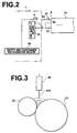
- the water content and/or solvent of the ink in the ink fountain evaporates to reduce the amount of ink as shown in Figure 3.
- the reduction is increased as the ceasing time from interruption of printing and resumption of the same is elongated. Accordingly, also when there is a ceasing time, there is a fear that the ink container (10) which yet holds ink therein can be recognized as an empty ink container (10) by mistake, and it is necessary to set suitably the inkless time.
- the empty ink container recognizing means 60 is provided with a ceasing time measuring means which measures the ceasing time from interruption of printing and resumption of the same and a correction table such as shown in Figure 4 where the ceasing time is related to parameters A to D so that one of the parameters A to D is stored in the storage means 8 of the ink container 10 and the empty ink container recognizing means 60 obtains and sets the inkless time by referring to the correction table on the basis of the ceasing time measured by the ceasing time measuring means and the parameter read out from the storage means 8 of the ink container 10.
- a suitable parameter which has been empirically determined in advance is stored.
- the storage means 8 may store different parameters for reference to the correction table shown in Figure 4 and for reference to the correction table shown in Figure 5.
- the storage means 8 may store the parameter A as the parameter for reference to the correction table shown in Figure 4 and the parameter B as the parameter for reference to the correction table shown in Figure 5.
- the inkless time may be recorded as a bar code. Otherwise, the inkless time may be recorded as a letter or a symbol.
- the correction table such as shown in Figure 4 or 5 may be stored in the memory IC 81 of the storage means 8 so that the empty ink container recognizing means 60 sets the inkless time referring to the correction table.
Landscapes
- Inking, Control Or Cleaning Of Printing Machines (AREA)
- Ink Jet (AREA)
Abstract
Description
and the inkless time is set on the basis of the parameter.
Claims (6)
- An ink supply method comprising, in a method where
supply of ink from an ink container to an ink fountain where the ink is temporarily stored between the ink is discharged from an ink container and the ink is supplied to the inner peripheral surface of a printing drum is started when the amount of ink in the ink fountain becomes smaller than a first threshold value and
is terminated when the amount of ink in the ink fountain becomes not smaller than a second threshold value after the supply of ink is started,
the elapsing time from the start of the supply of ink is measured and
it is recognized that the ink container is exhausted when the measured elapsing time from the start of the supply of ink becomes longer than a predetermined inkless time before the amount of ink in the ink fountain becomes not smaller than the second threshold value after the supply of ink is started,
the steps of
reading out a parameter from a storage means which is provided on the ink container to store a parameter representing an inkless time corresponding to the kind of the ink in the ink container, and
setting the inkless time on the basis of the parameter. - An ink supply method comprising, in a method where
supply of ink from an ink container to an ink fountain where the ink is temporarily stored between the ink is discharged from an ink container and the ink is supplied to the inner peripheral surface of a printing drum is started when the amount of ink in the ink fountain becomes smaller than a first threshold value and
is terminated when the amount of ink in the ink fountain becomes not smaller than a second threshold value after the supply of ink is started,
the elapsing time from the start of the supply of ink is measured and
it is recognized that the ink container is exhausted when the measured elapsing time from the start of the supply of ink becomes longer than a predetermined inkless time before the amount of ink in the ink fountain becomes not smaller than the second threshold value after the supply of ink is started, the steps of
measuring the ceasing time from interruption of printing to resumption of the same,
reading out a parameter corresponding to the measured ceasing time from a storage means which is provided on the ink container to store a parameter representing an inkless time corresponding to the kind of the ink in the ink container and the ceasing time, and
setting the inkless time on the basis of the parameter. - An ink supply system comprising
an ink supply means which supplies ink in an ink container to an ink fountain where the ink is temporarily stored between the ink is discharged from an ink container and the ink is supplied to the inner peripheral surface of a printing drum,
an ink amount detecting means which outputs an ink supply starting signal when the amount of ink in the ink fountain supplied by the ink supply means becomes smaller than a predetermined first threshold value and an ink supply terminating signal when the amount of ink in the ink fountain becomes not smaller than a predetermined second threshold value,
a time measuring means which measures the elapsing time from the time the ink supply starting signal is output from the ink amount detecting means,
an empty ink container recognizing means which recognizes that the ink container is exhausted when the elapsing time measured by the time measuring means becomes longer than a predetermined inkless time before the ink supply terminating signal is output, and
an ink supply control means which starts the ink supply means supplying the ink in response to the ink supply starting signal and stops the ink supply means from supplying the ink in response to the ink supply terminating signal,
wherein the improvement comprises that the empty ink container recognizing means reads out a parameter from a storage means which is provided on the ink container to store a parameter representing an inkless time corresponding to the kind of the ink in the ink container, and sets the inkless time on the basis of the parameter. - An ink supply system as defined in Claim 3 further comprising a ceasing time measuring means which measures a ceasing time from interruption of the action of the printing drum and resumption of the same,
wherein the parameter stored in the storage means represents an inkless time corresponding to the ceasing time and the kind of the ink in the ink container, and
the empty ink container recognizing means sets the inkless time on the basis of the parameter. - An ink container which is used for carrying out the ink supply method claimed in Claim 1 comprising a storage means which stores a parameter representing an inkless time corresponding to the kind of the ink therein.
- An ink container which is used for carrying out the ink supply method claimed in Claim2 comprising a storage means which stores a parameter representing an inkless time corresponding to the ceasing time and the kind of the ink in the ink container.
Applications Claiming Priority (3)
| Application Number | Priority Date | Filing Date | Title |
|---|---|---|---|
| JP2003016165 | 2003-01-24 | ||
| JP2003016165A JP2004223950A (en) | 2003-01-24 | 2003-01-24 | Ink supply method and apparatus, and ink container |
| PCT/JP2003/016042 WO2004065126A1 (en) | 2003-01-24 | 2003-12-15 | Method and system for supplying ink and ink container |
Publications (3)
| Publication Number | Publication Date |
|---|---|
| EP1586458A1 true EP1586458A1 (en) | 2005-10-19 |
| EP1586458A4 EP1586458A4 (en) | 2010-05-05 |
| EP1586458B1 EP1586458B1 (en) | 2011-08-24 |
Family
ID=32767461
Family Applications (1)
| Application Number | Title | Priority Date | Filing Date |
|---|---|---|---|
| EP03780770A Expired - Lifetime EP1586458B1 (en) | 2003-01-24 | 2003-12-15 | Method and system for supplying ink and ink container |
Country Status (5)
| Country | Link |
|---|---|
| US (1) | US8011298B2 (en) |
| EP (1) | EP1586458B1 (en) |
| JP (1) | JP2004223950A (en) |
| CN (1) | CN100418788C (en) |
| WO (1) | WO2004065126A1 (en) |
Families Citing this family (6)
| Publication number | Priority date | Publication date | Assignee | Title |
|---|---|---|---|---|
| JP4727250B2 (en) * | 2005-02-15 | 2011-07-20 | 東北リコー株式会社 | Stencil printing machine |
| JP5787396B2 (en) * | 2011-05-31 | 2015-09-30 | 理想科学工業株式会社 | Stencil printing machine |
| CN102501605A (en) * | 2011-10-11 | 2012-06-20 | 江苏锐毕利实业有限公司 | Method for controlling spray printing ink filling of rigid printed circuit board |
| CN105584237A (en) * | 2014-10-23 | 2016-05-18 | 上海华虹计通智能系统股份有限公司 | Stamp-pad ink adding device and stamping equipment provided with stamp-pad ink adding device |
| KR102400483B1 (en) * | 2015-10-02 | 2022-05-23 | 삼성디스플레이 주식회사 | device for fabricating organic light emitting display device, and fabricating method of organic light emitting display device using the same |
| US12263671B2 (en) * | 2018-12-20 | 2025-04-01 | Bobst Firenze S.R.L | Linear ink dispensing system |
Family Cites Families (14)
| Publication number | Priority date | Publication date | Assignee | Title |
|---|---|---|---|---|
| US3848529A (en) * | 1972-10-24 | 1974-11-19 | Baldwin Gegenheimer Corp | Ink level control system |
| US4479433A (en) * | 1978-04-21 | 1984-10-30 | Baldwin-Gegenheimer Corporation | Ink level control |
| JPS5555869A (en) * | 1978-10-18 | 1980-04-24 | Riso Kagaku Corp | Detector for amount of ink |
| DD212697A1 (en) * | 1982-10-26 | 1984-08-22 | Druckmaschinenwerk Planeta Rad | DISPLAY DEVICE FOR COLOR CONTROL SYSTEMS |
| JPS60161187A (en) * | 1984-02-01 | 1985-08-22 | Deyupuro Seikou Kk | Rotary press |
| US5460091A (en) * | 1990-10-30 | 1995-10-24 | Como Technologies, Inc. | Printing press ink supply system |
| JP3190148B2 (en) * | 1992-12-28 | 2001-07-23 | 理想科学工業株式会社 | Stencil printing machine |
| JP3523941B2 (en) | 1995-07-28 | 2004-04-26 | 理想科学工業株式会社 | Stencil printing machine |
| TW330907B (en) * | 1996-09-09 | 1998-05-01 | Riso Kagaku Corp | The ink container and ink supplied device for packing ink container |
| KR100307584B1 (en) * | 1998-02-27 | 2001-12-12 | 윤종용 | Apparatus for supplying ink for liquid electrographic printer |
| JP3697213B2 (en) * | 2001-02-09 | 2005-09-21 | キヤノン株式会社 | Liquid storage container and liquid stirring method |
| JP3543781B2 (en) * | 2001-04-13 | 2004-07-21 | セイコーエプソン株式会社 | Ink jet recording device |
| JP2002321434A (en) | 2001-04-25 | 2002-11-05 | Riso Kagaku Corp | Ink supply device for stencil printing |
| JP3932503B2 (en) * | 2001-07-02 | 2007-06-20 | 理想科学工業株式会社 | Ink amount detection method and apparatus |
-
2003
- 2003-01-24 JP JP2003016165A patent/JP2004223950A/en active Pending
- 2003-12-15 US US10/543,051 patent/US8011298B2/en not_active Expired - Fee Related
- 2003-12-15 CN CNB2003801091652A patent/CN100418788C/en not_active Expired - Lifetime
- 2003-12-15 EP EP03780770A patent/EP1586458B1/en not_active Expired - Lifetime
- 2003-12-15 WO PCT/JP2003/016042 patent/WO2004065126A1/en not_active Ceased
Non-Patent Citations (2)
| Title |
|---|
| No further relevant documents disclosed * |
| See also references of WO2004065126A1 * |
Also Published As
| Publication number | Publication date |
|---|---|
| JP2004223950A (en) | 2004-08-12 |
| US20060139417A1 (en) | 2006-06-29 |
| CN1741909A (en) | 2006-03-01 |
| EP1586458A4 (en) | 2010-05-05 |
| WO2004065126A1 (en) | 2004-08-05 |
| CN100418788C (en) | 2008-09-17 |
| EP1586458B1 (en) | 2011-08-24 |
| US8011298B2 (en) | 2011-09-06 |
Similar Documents
| Publication | Publication Date | Title |
|---|---|---|
| RU2333837C2 (en) | Cartridge and recording equipment | |
| CA2514936C (en) | Printer consumable having data storage for static and dynamic calibration data, and methods | |
| US8066350B2 (en) | Ink-jet recording apparatus | |
| JP3963777B2 (en) | Printer, method for managing printer information, and printer | |
| KR100516700B1 (en) | Printing apparatus and control methed therefor and its recording medium | |
| JPH08230213A (en) | Printer provided with device for identifying ink supply container | |
| JP2001130026A (en) | Ink jet printing apparatus, method for accessing memory device of ink cartridge, and method for controlling printing apparatus | |
| US8011298B2 (en) | System for supplying ink and ink container | |
| JPH08174863A (en) | Recording device with ink cartridge | |
| JP2004223849A (en) | A printing device and a method for accessing elements in the printing device. | |
| KR100636190B1 (en) | An image forming apparatus and method for automatically recognizing the type of thermal transfer head and printing an image | |
| US8061794B2 (en) | Method and apparatus for spoofing imaging devices | |
| JP2006127500A (en) | Printing apparatus, printing system, and printing apparatus driver program | |
| JPH08267785A (en) | Inkjet recording device | |
| JP2002321434A (en) | Ink supply device for stencil printing | |
| US20060071958A1 (en) | Pen alignment method and device for printing apparatus | |
| JP2007137524A (en) | Image recording device | |
| JP2713175B2 (en) | Inkjet printer | |
| JP2005177993A (en) | Printing apparatus, printing agent storage container for the apparatus, and printing system | |
| US20120026223A1 (en) | Method and Apparatus for Spoofing Imaging Devices | |
| JP2004188634A (en) | Printing apparatus, ink tank, and information collecting method | |
| JP2023178869A (en) | Inkjet printer, liquid discharge device, control method of liquid discharge device, and program | |
| JP2000351221A (en) | Inkjet printer | |
| JP4193002B2 (en) | Printer and error check method in printer | |
| KR19990071090A (en) | How to automatically load the head cartridge to the replacement position |
Legal Events
| Date | Code | Title | Description |
|---|---|---|---|
| PUAI | Public reference made under article 153(3) epc to a published international application that has entered the european phase |
Free format text: ORIGINAL CODE: 0009012 |
|
| 17P | Request for examination filed |
Effective date: 20050708 |
|
| AK | Designated contracting states |
Kind code of ref document: A1 Designated state(s): AT BE BG CH CY CZ DE DK EE ES FI FR GB GR HU IE IT LI LU MC NL PT RO SE SI SK TR |
|
| RBV | Designated contracting states (corrected) |
Designated state(s): DE FR GB |
|
| RIN1 | Information on inventor provided before grant (corrected) |
Inventor name: OSHIMA, KENJI,C/O RISO KAGAKU CORP. R & D CENTER Inventor name: IWAMOTO, MANABU,C/ORISO KAGAKU CORP. R & D CENTER |
|
| A4 | Supplementary search report drawn up and despatched |
Effective date: 20100401 |
|
| 17Q | First examination report despatched |
Effective date: 20100722 |
|
| GRAP | Despatch of communication of intention to grant a patent |
Free format text: ORIGINAL CODE: EPIDOSNIGR1 |
|
| RIC1 | Information provided on ipc code assigned before grant |
Ipc: B41L 13/18 20060101AFI20110131BHEP |
|
| RIN1 | Information on inventor provided before grant (corrected) |
Inventor name: IWAMOTO, MANABU,C/O RISO KAGAKU CORPORATION R & D Inventor name: OSHIMA, KENJI,C/O RISO KAGAKU CORPORATION R & D CE |
|
| GRAS | Grant fee paid |
Free format text: ORIGINAL CODE: EPIDOSNIGR3 |
|
| GRAA | (expected) grant |
Free format text: ORIGINAL CODE: 0009210 |
|
| AK | Designated contracting states |
Kind code of ref document: B1 Designated state(s): DE FR GB |
|
| REG | Reference to a national code |
Ref country code: GB Ref legal event code: FG4D |
|
| REG | Reference to a national code |
Ref country code: DE Ref legal event code: R096 Ref document number: 60338202 Country of ref document: DE Effective date: 20111027 |
|
| PLBE | No opposition filed within time limit |
Free format text: ORIGINAL CODE: 0009261 |
|
| STAA | Information on the status of an ep patent application or granted ep patent |
Free format text: STATUS: NO OPPOSITION FILED WITHIN TIME LIMIT |
|
| 26N | No opposition filed |
Effective date: 20120525 |
|
| REG | Reference to a national code |
Ref country code: DE Ref legal event code: R097 Ref document number: 60338202 Country of ref document: DE Effective date: 20120525 |
|
| REG | Reference to a national code |
Ref country code: FR Ref legal event code: PLFP Year of fee payment: 13 |
|
| REG | Reference to a national code |
Ref country code: FR Ref legal event code: PLFP Year of fee payment: 14 |
|
| REG | Reference to a national code |
Ref country code: DE Ref legal event code: R082 Ref document number: 60338202 Country of ref document: DE Representative=s name: KLUNKER IP PATENTANWAELTE PARTG MBB, DE |
|
| REG | Reference to a national code |
Ref country code: FR Ref legal event code: PLFP Year of fee payment: 15 |
|
| PGFP | Annual fee paid to national office [announced via postgrant information from national office to epo] |
Ref country code: FR Payment date: 20201222 Year of fee payment: 18 Ref country code: GB Payment date: 20201224 Year of fee payment: 18 |
|
| PGFP | Annual fee paid to national office [announced via postgrant information from national office to epo] |
Ref country code: DE Payment date: 20201223 Year of fee payment: 18 |
|
| REG | Reference to a national code |
Ref country code: DE Ref legal event code: R119 Ref document number: 60338202 Country of ref document: DE |
|
| GBPC | Gb: european patent ceased through non-payment of renewal fee |
Effective date: 20211215 |
|
| PG25 | Lapsed in a contracting state [announced via postgrant information from national office to epo] |
Ref country code: GB Free format text: LAPSE BECAUSE OF NON-PAYMENT OF DUE FEES Effective date: 20211215 Ref country code: DE Free format text: LAPSE BECAUSE OF NON-PAYMENT OF DUE FEES Effective date: 20220701 |
|
| PG25 | Lapsed in a contracting state [announced via postgrant information from national office to epo] |
Ref country code: FR Free format text: LAPSE BECAUSE OF NON-PAYMENT OF DUE FEES Effective date: 20211231 |