EP1585120A1 - Miniaturized optical pickup - Google Patents
Miniaturized optical pickup Download PDFInfo
- Publication number
- EP1585120A1 EP1585120A1 EP04008548A EP04008548A EP1585120A1 EP 1585120 A1 EP1585120 A1 EP 1585120A1 EP 04008548 A EP04008548 A EP 04008548A EP 04008548 A EP04008548 A EP 04008548A EP 1585120 A1 EP1585120 A1 EP 1585120A1
- Authority
- EP
- European Patent Office
- Prior art keywords
- laser diode
- optical pickup
- light beam
- recording medium
- optical recording
- Prior art date
- Legal status (The legal status is an assumption and is not a legal conclusion. Google has not performed a legal analysis and makes no representation as to the accuracy of the status listed.)
- Withdrawn
Links
- 230000003287 optical effect Effects 0.000 title claims abstract description 61
- 230000010287 polarization Effects 0.000 claims abstract description 12
- 238000007493 shaping process Methods 0.000 claims description 5
- 201000009310 astigmatism Diseases 0.000 description 4
- 238000000034 method Methods 0.000 description 4
- 238000001514 detection method Methods 0.000 description 3
- 230000000694 effects Effects 0.000 description 3
- 230000005855 radiation Effects 0.000 description 2
- 238000004624 confocal microscopy Methods 0.000 description 1
- 230000008878 coupling Effects 0.000 description 1
- 238000010168 coupling process Methods 0.000 description 1
- 238000005859 coupling reaction Methods 0.000 description 1
- 238000001914 filtration Methods 0.000 description 1
Images

Classifications
-
- G—PHYSICS
- G11—INFORMATION STORAGE
- G11B—INFORMATION STORAGE BASED ON RELATIVE MOVEMENT BETWEEN RECORD CARRIER AND TRANSDUCER
- G11B7/00—Recording or reproducing by optical means, e.g. recording using a thermal beam of optical radiation by modifying optical properties or the physical structure, reproducing using an optical beam at lower power by sensing optical properties; Record carriers therefor
- G11B7/12—Heads, e.g. forming of the optical beam spot or modulation of the optical beam
- G11B7/125—Optical beam sources therefor, e.g. laser control circuitry specially adapted for optical storage devices; Modulators, e.g. means for controlling the size or intensity of optical spots or optical traces
- G11B7/126—Circuits, methods or arrangements for laser control or stabilisation
- G11B7/1263—Power control during transducing, e.g. by monitoring
-
- G—PHYSICS
- G11—INFORMATION STORAGE
- G11B—INFORMATION STORAGE BASED ON RELATIVE MOVEMENT BETWEEN RECORD CARRIER AND TRANSDUCER
- G11B7/00—Recording or reproducing by optical means, e.g. recording using a thermal beam of optical radiation by modifying optical properties or the physical structure, reproducing using an optical beam at lower power by sensing optical properties; Record carriers therefor
- G11B7/12—Heads, e.g. forming of the optical beam spot or modulation of the optical beam
- G11B7/135—Means for guiding the beam from the source to the record carrier or from the record carrier to the detector
- G11B7/1365—Separate or integrated refractive elements, e.g. wave plates
-
- G—PHYSICS
- G11—INFORMATION STORAGE
- G11B—INFORMATION STORAGE BASED ON RELATIVE MOVEMENT BETWEEN RECORD CARRIER AND TRANSDUCER
- G11B7/00—Recording or reproducing by optical means, e.g. recording using a thermal beam of optical radiation by modifying optical properties or the physical structure, reproducing using an optical beam at lower power by sensing optical properties; Record carriers therefor
- G11B7/12—Heads, e.g. forming of the optical beam spot or modulation of the optical beam
- G11B7/135—Means for guiding the beam from the source to the record carrier or from the record carrier to the detector
- G11B7/1372—Lenses
- G11B7/1378—Separate aberration correction lenses; Cylindrical lenses to generate astigmatism; Beam expanders
Definitions
- the present invention relates to a miniaturized optical pickup, and to an apparatus for reading from and/or writing to optical recording media using such miniaturized optical pickup.
- Miniaturized optical disk drives are very attractive for mobile products such as digital cameras. In order to miniaturize an optical disk drive, it is necessary to reduce the size of the optical pickup used in such a disk drive.
- a conventional optical pickup is illustrated in Fig. 1.
- a laser diode 1 having a laser cavity 2 generates a light beam, which passes through a beam splitter 3 and is focused on an optical recording medium 5 by an objective lens 4.
- the light beam reflected by the optical recording medium 5 passes again through the objective lens 4 and is at least partially deflected by the beam splitter 3.
- the deflected light beam is then focused onto a four-element photo detector 7 by an astigmatic focusing lens 6 to generate a focus error signal using the astigmatism method and a tracking error signal using the push-pull method.
- This conventional optical pickup has the disadvantage that the beam path between the beam splitter 3 and the photo detector 7 needs additional space and impedes miniaturization.
- Juskaitis et al. present the idea to send radiation reflected from a specimen back through the laser cavity. The resulting signal is detected by using the feedback effects that are caused by the interference of the returning light and the laser.
- an optical pickup including a laser diode having a laser cavity, and a photo detector placed behind the laser cavity, wherein a light beam emitted by the laser diode and reflected by an optical recording medium is transmitted back through the laser cavity and impinges on the photo detector, wherein the optical pickup further includes a polarization rotating element placed between the laser diode and the optical recording medium such that the direction of polarization of the reflected light beam is perpendicular to the direction of polarization of the light beam emitted by the laser diode.
- a beam-shaping element is introduced in the beam path between the laser diode and the optical recording medium.
- the beam-shaping element is used, as usual, to modify the intensity distribution of the light beam.
- the beam-shaping element replaces the astigmatic focus lens, as beam-shapers introduce strong astigmatism provided that the light beam is defocused. This has the advantage that no additional astigmatic focusing lens is needed for generating the focus error signal.
- a polarizing, astigmatic focusing lens is placed in the beam path between the laser diode and the optical recording medium to modify the light beam returning from the optical recording medium in such a way that it allows the generation of a focus and a track error signal with a suitable detector pattern.
- a suitable detector pattern is, for example, a four-element photo detector.
- the polarizing, astigmatic focusing lens favourably is a double refractive lens. When the polarizing, astigmatic focusing lens is placed close to the objective lens the total length of the detection path is reduced to a minimum
- a linear polarizer is placed between the laser diode and the photo detector.
- This linear polarizer blocks the light that is emitted by the laser diode, but transmits the light beam returning from the optical recording medium. In this way only the light reflected from the optical recording medium is detected by the photo detector.
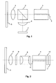
- Fig. 2 shows the optical layout of the proposed optical pickup.
- a linear polarized light beam emitted by a laser diode 1 is shaped by a beam shaper 8, transmitted through a quarter wave plate 9 and focused on an optical recording medium 5 by an objective lens 4.
- the light beam reflected by the optical recording medium 5 passes again through the objective lens 4, the quarter wave plate 9 and the beam shaper 8.
- the light beam is then transmitted through the laser cavity 2 and reaches a four-element photo detector 7 to generate a tracking error signal using the push-pull method and a focus error signal using the astigmatism method.
- Due to the quarter wave plate 9 the direction of polarization of the returning light beam is rotated by 90° relative to the direction of polarization of the light beam emitted by the laser diode 1.
- a linear polarizer 10 between the laser diode 1 and the photo detector 7 blocks the light that is emitted by the laser diode 1, but transmits the light beam returning from the optical recording medium 5. If the light beam returning from the optical recording medium 5 is slightly defocused, the beam shaper 8 introduces astigmatism and produces an elliptically shaped focus spot on the photo detector 7, which may be used to generate the focus error signal. Of course, instead of the beam shaper 8 and additional astigmatic focusing lens 6 may also be used for producing the elliptically shaped focus spot
- Fig. 3 depicts an optical pickup which is similar to the one shown in Fig. 2, but where the beam shaper 8 is replaced by a polarizing, astigmatic focusing lens 11.
- This polarizing, astigmatic focusing lens 11 modifies the light beam returning from the optical recording medium 5 in such a way that it allows the generation of a focus and a track error signal with a suitable detector pattern, i.e. a four-element photo detector 7.
- This polarizing, astigmatic focusing lens 11 may, for example, be made of a bi-refractive material with the following design: for a p-polarized light beam the lens 11 acts like a flat lens and for an s-polarized light beam it acts like an astigmatic lens.
- the above described polarizing, astigmatic focusing lens 11 can also be used to miniaturize a conventional pickup, as illustrated in Fig. 4.
- the polarizing, astigmatic focusing lens 11 is placed close to the objective lens 4.
- the additional optical path between the astigmatic lens 6 and the photo detector 7 as in Fig. 1 is avoided, i.e. the photo detector 7 is placed close to the beam splitter 3.
- a similar reduction of the optical path is also achieved, in addition to a beam-shaping effect, by replacing the polarizing, astigmatic focusing lens 11 with the beam shaper 8 of Fig 2.
Landscapes
- Physics & Mathematics (AREA)
- Optics & Photonics (AREA)
- Optical Head (AREA)
Abstract
The present invention relates to a miniaturized optical
pickup, and to an apparatus for reading from and/or writing
to optical recording media using such miniaturized optical
pickup.
It is an object of the invention to propose a new design for
a miniaturized optical pickup.
According to the invention an optical pickup including a
laser diode (1) having a laser cavity (2), and a photo
detector (7) placed behind the laser cavity (2), wherein a
light beam emitted by the laser diode (1) and reflected by an
optical recording medium (5) is transmitted back through the
laser cavity (2) and impinges on the photo detector (7),
further includes a polarization rotating element (9) placed
between the laser diode (1) and the optical recording medium
(5) such that the direction of polarization of the reflected
light beam is perpendicular to the direction of polarization
of the light beam emitted by the laser diode (1).
Description
The present invention relates to a miniaturized optical
pickup, and to an apparatus for reading from and/or writing
to optical recording media using such miniaturized optical
pickup.
Miniaturized optical disk drives are very attractive for
mobile products such as digital cameras. In order to
miniaturize an optical disk drive, it is necessary to reduce
the size of the optical pickup used in such a disk drive.
A conventional optical pickup is illustrated in Fig. 1. A
laser diode 1 having a laser cavity 2 generates a light beam,
which passes through a beam splitter 3 and is focused on an
optical recording medium 5 by an objective lens 4. The light
beam reflected by the optical recording medium 5 passes again
through the objective lens 4 and is at least partially
deflected by the beam splitter 3. The deflected light beam is
then focused onto a four-element photo detector 7 by an
astigmatic focusing lens 6 to generate a focus error signal
using the astigmatism method and a tracking error signal
using the push-pull method. This conventional optical pickup
has the disadvantage that the beam path between the beam
splitter 3 and the photo detector 7 needs additional space
and impedes miniaturization.
In "Spatial filtering by laser detection in confocal
microscopy", Optics Letters Vol. 18 (1993), pp. 1135-1137,
Juskaitis et al. present the idea to send radiation reflected
from a specimen back through the laser cavity. The resulting
signal is detected by using the feedback effects that are
caused by the interference of the returning light and the
laser.
It is an object of the invention to propose an alternative
design for a miniaturized optical pickup.
According to the invention this object is achieved by an
optical pickup including a laser diode having a laser cavity,
and a photo detector placed behind the laser cavity, wherein
a light beam emitted by the laser diode and reflected by an
optical recording medium is transmitted back through the
laser cavity and impinges on the photo detector, wherein the
optical pickup further includes a polarization rotating
element placed between the laser diode and the optical
recording medium such that the direction of polarization of
the reflected light beam is perpendicular to the direction of
polarization of the light beam emitted by the laser diode.
While in the prior art the feedback effects that are caused
by the interference of the returning light beam and the laser
diode are used for signal detection this feedback is
suppressed by introducing a polarization rotating element,
e.g. a quarter wave plate. Instead, the transmitted light is
measured directly with the detector placed behind the laser
diode. The proposed new design requires a minimum of optical
components, as the beam splitter can be saved. All the
components are aligned along a single (optical) axis. By
stacking all optical components a very compact pickup can be
build.
Favourably, a beam-shaping element is introduced in the beam
path between the laser diode and the optical recording
medium. For the light beam emitted by the laser diode the
beam-shaping element is used, as usual, to modify the
intensity distribution of the light beam. For the light beam
reflected by the optical recording medium the beam-shaping
element replaces the astigmatic focus lens, as beam-shapers
introduce strong astigmatism provided that the light beam is
defocused. This has the advantage that no additional
astigmatic focusing lens is needed for generating the focus
error signal.
Alternatively, a polarizing, astigmatic focusing lens is
placed in the beam path between the laser diode and the
optical recording medium to modify the light beam returning
from the optical recording medium in such a way that it
allows the generation of a focus and a track error signal
with a suitable detector pattern. A suitable detector pattern
is, for example, a four-element photo detector. The
polarizing, astigmatic focusing lens favourably is a double
refractive lens. When the polarizing, astigmatic focusing
lens is placed close to the objective lens the total length
of the detection path is reduced to a minimum
Favourably, a linear polarizer is placed between the laser
diode and the photo detector. This linear polarizer blocks
the light that is emitted by the laser diode, but transmits
the light beam returning from the optical recording medium.
In this way only the light reflected from the optical
recording medium is detected by the photo detector.
For a better understanding of the invention, exemplary
embodiments are specified in the following description with
reference to the figures. It is understood that the invention
is not limited to these exemplary embodiments and that
specified features can also expediently be combined and/or
modified without departing from the scope of the present
invention. In the figures:
- Fig. 1
- shows the optical layout of a conventional optical pickup;
- Fig. 2
- depicts the optical layout of a miniaturized optical pickup according to the invention;
- Fig. 3
- illustrates a further optical layout of a miniaturized optical pickup; and
- Fig. 4
- depicts a conventional optical pickup with reduced size.
Fig. 2 shows the optical layout of the proposed optical
pickup. A linear polarized light beam emitted by a laser
diode 1 is shaped by a beam shaper 8, transmitted through a
quarter wave plate 9 and focused on an optical recording
medium 5 by an objective lens 4. The light beam reflected by
the optical recording medium 5 passes again through the
objective lens 4, the quarter wave plate 9 and the beam
shaper 8. The light beam is then transmitted through the
laser cavity 2 and reaches a four-element photo detector 7 to
generate a tracking error signal using the push-pull method
and a focus error signal using the astigmatism method. Due to
the quarter wave plate 9 the direction of polarization of the
returning light beam is rotated by 90° relative to the
direction of polarization of the light beam emitted by the
laser diode 1. This reduces the coupling between the
radiation generated in the laser cavity 2 and the returning
light beam thereby reducing the laser noise. A linear
polarizer 10 between the laser diode 1 and the photo detector
7 blocks the light that is emitted by the laser diode 1, but
transmits the light beam returning from the optical recording
medium 5. If the light beam returning from the optical
recording medium 5 is slightly defocused, the beam shaper 8
introduces astigmatism and produces an elliptically shaped
focus spot on the photo detector 7, which may be used to
generate the focus error signal. Of course, instead of the
beam shaper 8 and additional astigmatic focusing lens 6 may
also be used for producing the elliptically shaped focus spot
Fig. 3 depicts an optical pickup which is similar to the one
shown in Fig. 2, but where the beam shaper 8 is replaced by a
polarizing, astigmatic focusing lens 11. This polarizing,
astigmatic focusing lens 11 modifies the light beam returning
from the optical recording medium 5 in such a way that it
allows the generation of a focus and a track error signal
with a suitable detector pattern, i.e. a four-element photo
detector 7. This polarizing, astigmatic focusing lens 11 may,
for example, be made of a bi-refractive material with the
following design: for a p-polarized light beam the lens 11
acts like a flat lens and for an s-polarized light beam it
acts like an astigmatic lens.
The above described polarizing, astigmatic focusing lens 11
can also be used to miniaturize a conventional pickup, as
illustrated in Fig. 4. In this figure the polarizing,
astigmatic focusing lens 11 is placed close to the objective
lens 4. In this way the additional optical path between the
astigmatic lens 6 and the photo detector 7 as in Fig. 1 is
avoided, i.e. the photo detector 7 is placed close to the
beam splitter 3. A similar reduction of the optical path is
also achieved, in addition to a beam-shaping effect, by
replacing the polarizing, astigmatic focusing lens 11 with
the beam shaper 8 of Fig 2.
Claims (5)
- Optical pickup including a laser diode (1) having a laser cavity (2), and a photo detector (7) placed behind the laser cavity (2), wherein a light beam emitted by the laser diode (1) and reflected by an optical recording medium (5) is transmitted back through the laser cavity (2) and impinges on the photo detector (7), characterized in that the optical pickup further includes a polarization rotating element (9) placed between the laser diode (1) and the optical recording medium (5) such that the direction of polarization of the reflected light beam is perpendicular to the direction of polarization of the light beam emitted by the laser diode (1).
- Optical pickup according to claim 1, further including a beam-shaping element (8) in the beam path between the laser diode (1) and the optical recording medium (5).
- Optical pickup according to claim 1, further including a polarizing, astigmatic focusing lens (11) in the beam path between the laser diode (1) and the optical recording medium (5) to modify the light beam returning from the optical recording medium (5) in such a way that it allows the generation of a focus and a track error signal with a suitable detector pattern.
- Optical pickup according to one of claims 1 to 3, wherein a linear polarizer (10) is placed between the laser diode (1) and the photo detector (7).
- Apparatus for reading from and/or writing to optical recording media, characterized in that it includes an optical pickup according to one of claims 1 to 4.
Priority Applications (1)
| Application Number | Priority Date | Filing Date | Title |
|---|---|---|---|
| EP04008548A EP1585120A1 (en) | 2004-04-08 | 2004-04-08 | Miniaturized optical pickup |
Applications Claiming Priority (1)
| Application Number | Priority Date | Filing Date | Title |
|---|---|---|---|
| EP04008548A EP1585120A1 (en) | 2004-04-08 | 2004-04-08 | Miniaturized optical pickup |
Publications (1)
| Publication Number | Publication Date |
|---|---|
| EP1585120A1 true EP1585120A1 (en) | 2005-10-12 |
Family
ID=34896021
Family Applications (1)
| Application Number | Title | Priority Date | Filing Date |
|---|---|---|---|
| EP04008548A Withdrawn EP1585120A1 (en) | 2004-04-08 | 2004-04-08 | Miniaturized optical pickup |
Country Status (1)
| Country | Link |
|---|---|
| EP (1) | EP1585120A1 (en) |
Citations (5)
| Publication number | Priority date | Publication date | Assignee | Title |
|---|---|---|---|---|
| JPS54141105A (en) * | 1978-04-25 | 1979-11-02 | Mitsubishi Electric Corp | Information reproduction device using laser beams |
| US4449204A (en) * | 1980-03-31 | 1984-05-15 | Agency Of Industrial Science And Technology | Information processing apparatus using a semiconductor laser diode |
| JPH0210528A (en) * | 1988-06-29 | 1990-01-16 | Nec Corp | Optical pickup device |
| JPH06103604A (en) * | 1992-09-22 | 1994-04-15 | Matsushita Electric Ind Co Ltd | Optical head device |
| US5867315A (en) * | 1995-07-31 | 1999-02-02 | Pioneer Electronic Corporation | Crystal optic lens and an optical system for an optical pickup device |
-
2004
- 2004-04-08 EP EP04008548A patent/EP1585120A1/en not_active Withdrawn
Patent Citations (5)
| Publication number | Priority date | Publication date | Assignee | Title |
|---|---|---|---|---|
| JPS54141105A (en) * | 1978-04-25 | 1979-11-02 | Mitsubishi Electric Corp | Information reproduction device using laser beams |
| US4449204A (en) * | 1980-03-31 | 1984-05-15 | Agency Of Industrial Science And Technology | Information processing apparatus using a semiconductor laser diode |
| JPH0210528A (en) * | 1988-06-29 | 1990-01-16 | Nec Corp | Optical pickup device |
| JPH06103604A (en) * | 1992-09-22 | 1994-04-15 | Matsushita Electric Ind Co Ltd | Optical head device |
| US5867315A (en) * | 1995-07-31 | 1999-02-02 | Pioneer Electronic Corporation | Crystal optic lens and an optical system for an optical pickup device |
Non-Patent Citations (3)
| Title |
|---|
| PATENT ABSTRACTS OF JAPAN vol. 004, no. 001 (E - 163) 8 January 1980 (1980-01-08) * |
| PATENT ABSTRACTS OF JAPAN vol. 014, no. 150 (P - 1025) 22 March 1990 (1990-03-22) * |
| PATENT ABSTRACTS OF JAPAN vol. 018, no. 379 (P - 1771) 15 July 1994 (1994-07-15) * |
Similar Documents
| Publication | Publication Date | Title |
|---|---|---|
| KR100310761B1 (en) | Compatible Recording and / or Playback Devices | |
| US20030053397A1 (en) | Optical head apparatus including two light sources and one photodetector | |
| WO2008039156A1 (en) | Optical focusing system and method | |
| KR100798197B1 (en) | Anamorphic prism, optical head and optical record / playback device | |
| JP2001195772A (en) | Optical pickup device | |
| CN1445764A (en) | Optical pick device | |
| JPH10333025A (en) | Optical pickup device | |
| JP3482154B2 (en) | Optical pickup device | |
| JPS586534A (en) | Optical device of playback device | |
| KR100207720B1 (en) | Optical pickup apparatus for recording and reproducing | |
| JPS6040538A (en) | Optical information reader | |
| KR100455477B1 (en) | Optical pickup | |
| JP3547286B2 (en) | Optical pickup device | |
| JPH0863778A (en) | Optical pickup | |
| KR100248023B1 (en) | Super resolution optical pickup for various type disc | |
| JP2006309851A (en) | Optical head device and information recording / reproducing device | |
| JPH0332141B2 (en) | ||
| JP2538192B2 (en) | Optical disk drive | |
| JPH11261171A (en) | Optical device, optical pickup and optical disk device using the same | |
| JPWO2008114406A1 (en) | Optical pickup and playback device | |
| JPH04178924A (en) | Focus control mechanism | |
| JP2004348831A (en) | Optical pickup device | |
| JPH0798882A (en) | Optical pickup device | |
| JP2004348832A (en) | Optical pickup device | |
| JPS6120235A (en) | Optical recording and reproducing device equipped with two light sources |
Legal Events
| Date | Code | Title | Description |
|---|---|---|---|
| PUAI | Public reference made under article 153(3) epc to a published international application that has entered the european phase |
Free format text: ORIGINAL CODE: 0009012 |
|
| AK | Designated contracting states |
Kind code of ref document: A1 Designated state(s): AT BE BG CH CY CZ DE DK EE ES FI FR GB GR HU IE IT LI LU MC NL PL PT RO SE SI SK TR |
|
| AX | Request for extension of the european patent |
Extension state: AL HR LT LV MK |
|
| AKX | Designation fees paid | ||
| STAA | Information on the status of an ep patent application or granted ep patent |
Free format text: STATUS: THE APPLICATION IS DEEMED TO BE WITHDRAWN |
|
| 18D | Application deemed to be withdrawn |
Effective date: 20060413 |
|
| REG | Reference to a national code |
Ref country code: DE Ref legal event code: 8566 |