EP1584947A2 - Ruggedized scintillation detector with low energy detection capabilities - Google Patents
Ruggedized scintillation detector with low energy detection capabilities Download PDFInfo
- Publication number
- EP1584947A2 EP1584947A2 EP05251981A EP05251981A EP1584947A2 EP 1584947 A2 EP1584947 A2 EP 1584947A2 EP 05251981 A EP05251981 A EP 05251981A EP 05251981 A EP05251981 A EP 05251981A EP 1584947 A2 EP1584947 A2 EP 1584947A2
- Authority
- EP
- European Patent Office
- Prior art keywords
- crystal
- radiation detector
- housing
- springs
- photomultiplier tube
- Prior art date
- Legal status (The legal status is an assumption and is not a legal conclusion. Google has not performed a legal analysis and makes no representation as to the accuracy of the status listed.)
- Granted
Links
Images


Classifications
-
- G—PHYSICS
- G01—MEASURING; TESTING
- G01T—MEASUREMENT OF NUCLEAR OR X-RADIATION
- G01T1/00—Measuring X-radiation, gamma radiation, corpuscular radiation, or cosmic radiation
- G01T1/16—Measuring radiation intensity
- G01T1/20—Measuring radiation intensity with scintillation detectors
- G01T1/202—Measuring radiation intensity with scintillation detectors the detector being a crystal
-
- G—PHYSICS
- G01—MEASURING; TESTING
- G01T—MEASUREMENT OF NUCLEAR OR X-RADIATION
- G01T1/00—Measuring X-radiation, gamma radiation, corpuscular radiation, or cosmic radiation
- G01T1/16—Measuring radiation intensity
- G01T1/20—Measuring radiation intensity with scintillation detectors
Definitions
- This invention relates generally to radiation detectors and, more specifically, to a suspension and protection system for a radiation detector enclosed within a housing.
- the first drawback arises from the attenuation of the gamma rays as they pass through the (spring) steel springs. This prohibits the measurement of low energy gamma radiation (below 60 KeV).
- the second drawback comes from detectors with electrical insulation located radially between the outside of the detector and the inside of the housing. In this case, the steel springs conduct electricity, thereby undesirably forming a circuit between the detector's outer diameter and the housing's inner diameter.
- a detector By replacing the spring steel with a material that attenuates the gamma rays less, but still provides a comparable degree of shock and vibration isolation, a detector can be constructed that will exhibit significantly better performance at low energy gamma levels, i.e., below 60 KeV. Using non-metallic springs also prevents formation of the aforementioned electrical circuit.
- the detector includes a scintillation crystal (usually sodium iodide doped with thallium); a photomultiplier tube (PMT); a metallic or plastic housing around the crystal and PMT; and a suspension system inside the housing, arranged about the outer dimensions of the crystal and PMT, as well as axially between the crystal and the housing.
- a scintillation crystal usually sodium iodide doped with thallium
- PMT photomultiplier tube
- metallic or plastic housing around the crystal and PMT
- suspension system inside the housing, arranged about the outer dimensions of the crystal and PMT, as well as axially between the crystal and the housing.
- the crystal in the exemplary embodiment is in the form of a cylinder.
- the cylinder dimensions may vary depending on the particular detector.
- the typical sodium iodide crystal doped with thallium (Nal(Tl)) has been used in radiation detectors since 1920 and has well known properties for gamma sensitivity, spectral resolution and light output.
- plastic or ceramic springs are placed around and along the length of the scintillation crystal as well as around and along the length of the PMT. Since the flat springs are fitted at spaced locations about the diameter of the crystal, and axially inserted into the cylindrical housing, they will be under some degree of flexion, thus allowing them to both dampen vibration as well as to protect the crystal from shock and to not amplify and transmit shock or vibration forces.
- the crystal is also provided with an axial suspension system including wave springs mounted between one end of the crystal and the detector housing. Compression plates to evenly distribute the load of the springs on the crystal will be used on either side of the springs.
- the axial suspension system is also used to maintain optical coupling between the crystal and PMT.
- suspension system described herein may be employed in crystal-only packages as well.
- the housing of the radiation detector may be made of any suitable plastic or metal material including thin walled aluminum or Mumetal® in cases where protection from magnetic fields is required.
- the invention relates to a radiation detector comprising a housing; a substantially cylindrical scintillation crystal and a photomultiplier tube assembly supported in the housing; and a plurality of elongated non-metallic springs extending along the crystal and the photomultiplier tube assembly, radially between the crystal and photomultiplier tube assembly and the housing.
- the invention in another aspect, relates to a radiation detector comprising a housing, a substantially cylindrical crystal and a photomultiplier tube assembly supported in the housing; a plurality of elongated plastic or ceramic springs circumferentially spaced about and extending along the crystal and the photomultiplier tube assembly, radially between the crystal and photomultiplier tube assembly and the housing; and at least one resilient member located at one end of the crystal, axially between an end wall of the housing and the crystal.
- the invention in another aspect, relates to a radiation detector comprising a housing, a substantially cylindrical crystal and a photomultiplier tube assembly supported in the housing; ceramic radial suspension means located radially between the crystal and photomultiplier tube assembly and the housing; and axial suspension means located at one end of the crystal, axially between an end wall of the housing and the crystal.
- the invention in still another aspect, relates to a scintillation crystal package comprising a housing; a substantially cylindrical scintillation crystal supported in the housing; and a plurality of elongated non-metallic springs extending along the crystal, radially between the crystal and the housing.
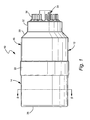
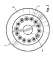
- a radiation detector 10 includes a housing 12 including a metal cap 14 that encloses a cylindrical scintillation crystal 16, and a cylindrical metal shield 18 that encloses a PMT 20.
- An enlarged open end 22 of the cap 14 telescopes over the end of the shield 18 and is adhered to the shield via adhesive 24.
- the housing portions 14, 18 are of generally elongated cylindrical shape, with cap 14 closed at its opposite end by an integral end wall 26.
- a distal end 28 of the metal shield 18 tapers at 30 to a smaller diameter free end 32 through which an electronics package 34 protrudes.
- Connectors 36 are adapted to receive cables that transmit the collected data to a monitoring device (not shown).
- Both the cap 14 and shield 18 are preferably made of any suitable plastic or metal material (e.g., aluminum) or where desired, a suitable magnetic shielding alloy such as Mumetal® (Ni77/Fe14/Cu5/Mo4).
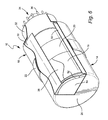
- the crystal 16 may be wrapped in a reflective tape 38 (e.g., Teflon®) ( Figure 6) and sized and shaped to fit within the metal cap 14, with a predetermined radial clearance to accommodate the suspension system described further herein.
- the crystal itself may be a cylindrical sodium iodide crystal doped with thalium (Nal(TI)). Typical measurements for the crystal may be 1" in diameter x 1" long, up to 4" in diameter and 4" long. These particular dimensions are not exclusive, however, but merely represent the general boundaries that those knowledgeable in the art have used previously to build radiation detectors for similar purposes.
- the PMT 20 may be any of several commercially available PMT's.
- the PMT has one end 40 with a diameter substantially identical to that of the crystal 16, with respective flat faces 42, 44 engaged or coupled as shown in Figure 4.
- a reduced diameter end 46, connected to end 40 via annular taper 48, is connected to the electronics package 34.
- Other detectors may incorporate uniform-diameter PMT's, and the invention here is not limited to any particular PMT configuration.
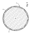
- a plurality of elongated, flat springs 50 are inserted into the housing 12, as best seen in Figure 5, in a circumferentially spaced array, radially between the crystal 16 and PMT 20 on the one hand, and the housing 12 on the other.
- Springs 50 are advantageously formed of non-metallic material, and preferably any suitable plastic or ceramic material which attenuates gamma rays less than spring steel, but provides an adequate degree of shock and vibration isolation.
- One suitable material is whit Delrin®, available from Du Pont.
- Springs 50 extend axially, i.e., parallel to the longitudinal axis of the detector, along substantially the entire length of the crystal and PMT.
- the detector suspension system may also include at least one annular wave spring ( Figures 4 and 6) located axially between a compression plate 54 (e.g., 030 inch thick white Delrin® or aluminum or other suitable materials) and the end wall 26.
- the spring 52 may be made of any suitable metal but could also be ceramic. It will be appreciated, however, that the wave spring 52 may be replaced by a suitable foam pad or other equivalent resilient member.
- the detector as described functions well at low levels of gamma radiation, for example, below 60 KeV, because the plastic or ceramic springs 50 do not attenuate gamma rays to the same degree as typical metal springs.
- the radiation detector as described may be used as a handheld gamma radiation detector inside a housing and used near an area through which people and vehicles, cargo or other similar things may pass. It may also be beneficial in conjunction with portals that "see” large amounts of vibration such as near trains and the like.
Landscapes
- Physics & Mathematics (AREA)
- Health & Medical Sciences (AREA)
- Life Sciences & Earth Sciences (AREA)
- General Physics & Mathematics (AREA)
- High Energy & Nuclear Physics (AREA)
- Molecular Biology (AREA)
- Spectroscopy & Molecular Physics (AREA)
- Chemical & Material Sciences (AREA)
- Crystallography & Structural Chemistry (AREA)
- Measurement Of Radiation (AREA)
Abstract
Description
Claims (10)
- A radiation detector (10) comprising a housing (12); a substantially cylindrical scintillation crystal (16) and a photomultiplier tube assembly (20) supported in said housing; and a plurality of elongated non-metallic springs (50) extending along said crystal and said photomultiplier tube assembly, radially between said crystal and photomultiplier tube assembly and said housing.
- The radiation detector of claim 1 wherein said springs (50) are composed of plastic material or a ceramic material and wherein the springs (50) are substantially flat.
- The radiation detector of claim 1 wherein said springs (50) extend axially along at least part of said crystal and photomultiplier tube assembly.
- The radiation detector of claim 1 wherein said springs (50) are under flexion in a direction substantially parallel to a longitudinal axis of said detector.
- The radiation detector of any preceding claim wherein said housing (12) is also cylindrical, and at least one resilient member (52) is located at one end of said crystal, axially between an end wall (26) of said housing and said one end of said crystal.
- The radiation detector of claim 5 wherein said at least one resilient member comprises at least one annular wave spring (52).
- The radiation detector of any preceding claim wherein said photomultiplier tube (20) is substantially round in cross section, with relatively larger and smaller diameter portions connected by a taper (48).
- The radiation detector of any preceding claim wherein an electronics package (34) is coupled to a distal end of said photomultiplier tube (20).
- The radiation detector of claim 6 wherein compression plates (54) are located on opposite axial sides of said at least one spring (52).
- The radiation detector of claim 6 wherein said at least one spring (52) comprises an annular wave spring.
Applications Claiming Priority (2)
| Application Number | Priority Date | Filing Date | Title |
|---|---|---|---|
| US10/820,039 US7170061B2 (en) | 2004-04-08 | 2004-04-08 | Ruggedized scintillation detector with low energy detection capabilities |
| US820039 | 2004-04-08 |
Publications (3)
| Publication Number | Publication Date |
|---|---|
| EP1584947A2 true EP1584947A2 (en) | 2005-10-12 |
| EP1584947A3 EP1584947A3 (en) | 2012-12-12 |
| EP1584947B1 EP1584947B1 (en) | 2016-08-10 |
Family
ID=34912710
Family Applications (1)
| Application Number | Title | Priority Date | Filing Date |
|---|---|---|---|
| EP05251981.6A Expired - Lifetime EP1584947B1 (en) | 2004-04-08 | 2005-03-30 | Ruggedized scintillation detector with low energy detection capabilities |
Country Status (4)
| Country | Link |
|---|---|
| US (1) | US7170061B2 (en) |
| EP (1) | EP1584947B1 (en) |
| JP (1) | JP2005300542A (en) |
| CN (1) | CN1680827B (en) |
Cited By (1)
| Publication number | Priority date | Publication date | Assignee | Title |
|---|---|---|---|---|
| CN107255828A (en) * | 2017-07-18 | 2017-10-17 | 中国科学院福建物质结构研究所 | Scintillation crystal unit piece, array module and detector |
Families Citing this family (25)
| Publication number | Priority date | Publication date | Assignee | Title |
|---|---|---|---|---|
| US7274023B2 (en) * | 2005-10-12 | 2007-09-25 | General Electric Company | Gamma-radiation detector module for portal applications |
| US7507969B1 (en) * | 2006-09-11 | 2009-03-24 | General Electric Company | Ruggedized radiation detector |
| US20090179153A1 (en) * | 2008-01-11 | 2009-07-16 | Siemens Medical Solutions Usa, Inc. | Alternate PMT Shield Method |
| US8039806B2 (en) * | 2008-05-06 | 2011-10-18 | Saint-Gobain Ceramics & Plastics, Inc. | Radiation detector device having an electrically conductive optical interface |
| CN101666226A (en) * | 2008-09-01 | 2010-03-10 | 天津大港油田圣达科技有限公司 | Probe sleeve with shock-proof and anti-collision performance |
| US8153981B2 (en) * | 2009-02-04 | 2012-04-10 | General Electric Company | Radiation detector assembly |
| US8058619B2 (en) * | 2009-03-27 | 2011-11-15 | General Electric Company | Radiation detector |
| BRPI1016011A2 (en) * | 2009-06-29 | 2016-04-26 | Baker Hugues Inc | Use of solid crystals as continuous light tubes to converge light to pmt window. |
| WO2011159911A2 (en) | 2010-06-18 | 2011-12-22 | Saint-Gobain Ceramics & Plastics, Inc. | Radiation detection system including a scintillating material and an optical fiber and method of using the same |
| WO2012024359A2 (en) | 2010-08-17 | 2012-02-23 | Saint-Gobain Ceramics & Plastics, Inc. | Ruggedized tool and detector device |
| US8879058B2 (en) * | 2010-11-05 | 2014-11-04 | The University Of Ottawa | Miniaturized multimodal cars endoscope |
| US9200949B2 (en) | 2011-12-12 | 2015-12-01 | Saint-Gobain Ceramics & Plastics, Inc. | Stand-alone photosensor assembly |
| US9395464B2 (en) | 2013-05-15 | 2016-07-19 | Schlumberger Technology Corporation | Scintillation detector package having radioactive reflective material therein |
| US8785841B1 (en) * | 2013-05-15 | 2014-07-22 | Schlumberger Technology Corporation | Scintillation detector package having radioactive window therein |
| US9715022B2 (en) | 2013-05-15 | 2017-07-25 | Schlumberger Technology Corporation | Scintillation detector package having radioactive support apparatus |
| US9895779B2 (en) | 2014-04-10 | 2018-02-20 | Temper Axle Products Corporation | Radial springs and methods of installing and uninstalling radial springs |
| RU2683798C2 (en) * | 2014-05-03 | 2019-04-02 | Толтек Груп, Ллс | Gamma detector protection for downhole operations |
| CN104319214B (en) * | 2014-09-30 | 2017-04-26 | 北京空间机电研究所 | Packaging method of anti-vibration type photoelectric detector |
| WO2017083114A1 (en) | 2015-11-13 | 2017-05-18 | Flir Detection, Inc. | Radiation detector module systems and methods |
| CN106442598A (en) * | 2016-09-06 | 2017-02-22 | 苏州大学 | Performance testing device for radiation luminescent material |
| CN110609313B (en) * | 2019-09-30 | 2024-12-20 | 南华大学 | Portable gamma radiation directional detector |
| DE102022105762A1 (en) | 2022-03-11 | 2023-09-14 | Vega Grieshaber Kg | Measuring device of a radiometric measuring device |
| DE102022133797A1 (en) * | 2022-12-19 | 2024-06-20 | Endress+Hauser SE+Co. KG | Radiometric level measurement |
| DE102023005444A1 (en) | 2023-02-09 | 2024-11-07 | Vega Grieshaber Kg | Radiometric measuring device and scintillator receiving element |
| DE102023103114B4 (en) * | 2023-02-09 | 2024-08-22 | Vega Grieshaber Kg | Radiometric measuring device and scintillator receiving element |
Family Cites Families (22)
| Publication number | Priority date | Publication date | Assignee | Title |
|---|---|---|---|---|
| US3087060A (en) * | 1959-06-30 | 1963-04-23 | Robert J Omohundro | Scintillation counter |
| US3704877A (en) * | 1971-02-22 | 1972-12-05 | John Nunes | Means and method of energy storage and damping |
| US4405863A (en) * | 1981-10-19 | 1983-09-20 | General Electric Company | Detector array retaining and positioning system |
| JPS62148364A (en) * | 1985-12-23 | 1987-07-02 | 東芝タンガロイ株式会社 | Ceramic elastic member |
| US4879463A (en) | 1987-12-14 | 1989-11-07 | Schlumberger Technology Corporation | Method and apparatus for subsurface formation evaluation |
| FR2636436B1 (en) | 1988-09-14 | 1990-11-30 | Schlumberger Prospection | SUBSIDENCE MEASUREMENT METHOD AND DEVICE |
| JPH0641976B2 (en) | 1989-02-07 | 1994-06-01 | 浜松ホトニクス株式会社 | Radiation detector storage device |
| US4994673A (en) * | 1989-06-06 | 1991-02-19 | Solon Technologies, Inc. | Ruggedized scintillation detector |
| US5120963A (en) * | 1991-01-15 | 1992-06-09 | Teleco Oilfield Services Inc. | Radiation detector assembly for formation logging apparatus |
| US5448615A (en) * | 1993-06-30 | 1995-09-05 | Eastman Kodak Company | Film cassette |
| US5408097A (en) | 1993-11-29 | 1995-04-18 | Schlumberger Technology Corporation | Method and apparatus for correcting natural gamma ray measurements for borehole fluid effects |
| JPH0741482U (en) * | 1993-12-28 | 1995-07-21 | 日本空調サービス株式会社 | Radiation measuring device |
| US5796109A (en) * | 1996-05-03 | 1998-08-18 | Frederick Energy Products | Unitized radiation detector assembly |
| US5869836A (en) * | 1996-09-20 | 1999-02-09 | Saint-Gobain Industrial Ceramics, Inc. | Scintillation detector with sleeved crystal boot |
| US6355932B1 (en) | 1998-02-25 | 2002-03-12 | General Electric Company | Maximum volume ruggedized nuclear detector |
| US6222192B1 (en) | 1998-07-06 | 2001-04-24 | Saint-Gobain Industrial Ceramics, Inc. | Scintillation detector without optical window |
| AU731139B2 (en) | 1998-08-24 | 2001-03-22 | Saint-Gobain Industrial Ceramics, Inc. | Modular radiation detector assembly |
| JP2001042038A (en) * | 1999-07-28 | 2001-02-16 | Nagase Landauer Ltd | Dosimeter for measuring neutron |
| JP4571252B2 (en) * | 1999-08-04 | 2010-10-27 | 燕 河田 | Measuring device using photomultiplier tube and afterpulse reduction method |
| US6465788B1 (en) | 1999-12-23 | 2002-10-15 | Frederick Energy Products Llc | Ruggedized photomultiplier tube and optical coupling in armored detector |
| US6657199B2 (en) | 2001-06-06 | 2003-12-02 | General Electric Company | Flexible dynamic housing |
| US7034305B2 (en) | 2002-03-22 | 2006-04-25 | General Electric Company | Instrumentation package and integrated radiation detector |
-
2004
- 2004-04-08 US US10/820,039 patent/US7170061B2/en not_active Expired - Lifetime
-
2005
- 2005-03-30 EP EP05251981.6A patent/EP1584947B1/en not_active Expired - Lifetime
- 2005-04-07 JP JP2005110860A patent/JP2005300542A/en active Pending
- 2005-04-08 CN CN2005100648744A patent/CN1680827B/en not_active Expired - Lifetime
Cited By (1)
| Publication number | Priority date | Publication date | Assignee | Title |
|---|---|---|---|---|
| CN107255828A (en) * | 2017-07-18 | 2017-10-17 | 中国科学院福建物质结构研究所 | Scintillation crystal unit piece, array module and detector |
Also Published As
| Publication number | Publication date |
|---|---|
| JP2005300542A (en) | 2005-10-27 |
| CN1680827A (en) | 2005-10-12 |
| EP1584947B1 (en) | 2016-08-10 |
| CN1680827B (en) | 2011-04-06 |
| EP1584947A3 (en) | 2012-12-12 |
| US20050224717A1 (en) | 2005-10-13 |
| US7170061B2 (en) | 2007-01-30 |
Similar Documents
| Publication | Publication Date | Title |
|---|---|---|
| EP1584947B1 (en) | Ruggedized scintillation detector with low energy detection capabilities | |
| JP4681811B2 (en) | Radiation detector | |
| EP1566661B1 (en) | Ruggedized scintillation detector for portal monitors and light pipe incorporated therein | |
| JP5086007B2 (en) | Radiation detector assembly | |
| US5742057A (en) | Unitized scintillation detector assembly with axial and radial suspension systems | |
| US6657199B2 (en) | Flexible dynamic housing | |
| US8646519B2 (en) | Low-profile suspension of logging sensor and method | |
| US10192646B2 (en) | Radiation shielding system | |
| AU2002312336A1 (en) | Flexible dynamic housing | |
| US7115873B2 (en) | Compound optical coupler and support mechanism |
Legal Events
| Date | Code | Title | Description |
|---|---|---|---|
| PUAI | Public reference made under article 153(3) epc to a published international application that has entered the european phase |
Free format text: ORIGINAL CODE: 0009012 |
|
| AK | Designated contracting states |
Kind code of ref document: A2 Designated state(s): AT BE BG CH CY CZ DE DK EE ES FI FR GB GR HU IE IS IT LI LT LU MC NL PL PT RO SE SI SK TR |
|
| AX | Request for extension of the european patent |
Extension state: AL BA HR LV MK YU |
|
| PUAL | Search report despatched |
Free format text: ORIGINAL CODE: 0009013 |
|
| AK | Designated contracting states |
Kind code of ref document: A3 Designated state(s): AT BE BG CH CY CZ DE DK EE ES FI FR GB GR HU IE IS IT LI LT LU MC NL PL PT RO SE SI SK TR |
|
| AX | Request for extension of the european patent |
Extension state: AL BA HR LV MK YU |
|
| RIC1 | Information provided on ipc code assigned before grant |
Ipc: G01T 1/202 20060101AFI20121108BHEP Ipc: G01T 1/20 20060101ALI20121108BHEP |
|
| 17P | Request for examination filed |
Effective date: 20130612 |
|
| RBV | Designated contracting states (corrected) |
Designated state(s): AT BE BG CH CY CZ DE DK EE ES FI FR GB GR HU IE IS IT LI LT LU MC NL PL PT RO SE SI SK TR |
|
| AKX | Designation fees paid |
Designated state(s): CH DE FR GB LI |
|
| 17Q | First examination report despatched |
Effective date: 20140718 |
|
| GRAP | Despatch of communication of intention to grant a patent |
Free format text: ORIGINAL CODE: EPIDOSNIGR1 |
|
| INTG | Intention to grant announced |
Effective date: 20160511 |
|
| GRAS | Grant fee paid |
Free format text: ORIGINAL CODE: EPIDOSNIGR3 |
|
| GRAA | (expected) grant |
Free format text: ORIGINAL CODE: 0009210 |
|
| AK | Designated contracting states |
Kind code of ref document: B1 Designated state(s): CH DE FR GB LI |
|
| REG | Reference to a national code |
Ref country code: GB Ref legal event code: FG4D |
|
| REG | Reference to a national code |
Ref country code: CH Ref legal event code: EP |
|
| REG | Reference to a national code |
Ref country code: DE Ref legal event code: R096 Ref document number: 602005049910 Country of ref document: DE |
|
| REG | Reference to a national code |
Ref country code: FR Ref legal event code: PLFP Year of fee payment: 13 |
|
| REG | Reference to a national code |
Ref country code: DE Ref legal event code: R097 Ref document number: 602005049910 Country of ref document: DE |
|
| PLBE | No opposition filed within time limit |
Free format text: ORIGINAL CODE: 0009261 |
|
| STAA | Information on the status of an ep patent application or granted ep patent |
Free format text: STATUS: NO OPPOSITION FILED WITHIN TIME LIMIT |
|
| 26N | No opposition filed |
Effective date: 20170511 |
|
| REG | Reference to a national code |
Ref country code: CH Ref legal event code: PL |
|
| PG25 | Lapsed in a contracting state [announced via postgrant information from national office to epo] |
Ref country code: CH Free format text: LAPSE BECAUSE OF NON-PAYMENT OF DUE FEES Effective date: 20170331 Ref country code: LI Free format text: LAPSE BECAUSE OF NON-PAYMENT OF DUE FEES Effective date: 20170331 |
|
| REG | Reference to a national code |
Ref country code: FR Ref legal event code: PLFP Year of fee payment: 14 |
|
| PGFP | Annual fee paid to national office [announced via postgrant information from national office to epo] |
Ref country code: DE Payment date: 20240220 Year of fee payment: 20 Ref country code: GB Payment date: 20240220 Year of fee payment: 20 |
|
| PGFP | Annual fee paid to national office [announced via postgrant information from national office to epo] |
Ref country code: FR Payment date: 20240221 Year of fee payment: 20 |
|
| REG | Reference to a national code |
Ref country code: DE Ref legal event code: R071 Ref document number: 602005049910 Country of ref document: DE |
|
| REG | Reference to a national code |
Ref country code: GB Ref legal event code: PE20 Expiry date: 20250329 |
|
| PG25 | Lapsed in a contracting state [announced via postgrant information from national office to epo] |
Ref country code: GB Free format text: LAPSE BECAUSE OF EXPIRATION OF PROTECTION Effective date: 20250329 |