EP1584812A1 - Fuel pump unit - Google Patents
Fuel pump unit Download PDFInfo
- Publication number
- EP1584812A1 EP1584812A1 EP04702421A EP04702421A EP1584812A1 EP 1584812 A1 EP1584812 A1 EP 1584812A1 EP 04702421 A EP04702421 A EP 04702421A EP 04702421 A EP04702421 A EP 04702421A EP 1584812 A1 EP1584812 A1 EP 1584812A1
- Authority
- EP
- European Patent Office
- Prior art keywords
- section
- pump
- motor
- fuel
- flow path
- Prior art date
- Legal status (The legal status is an assumption and is not a legal conclusion. Google has not performed a legal analysis and makes no representation as to the accuracy of the status listed.)
- Withdrawn
Links
- 239000000446 fuel Substances 0.000 title claims abstract description 167
- 238000001914 filtration Methods 0.000 claims abstract description 84
- 238000003780 insertion Methods 0.000 abstract description 7
- 230000037431 insertion Effects 0.000 abstract description 7
- 238000007789 sealing Methods 0.000 description 23
- 238000003825 pressing Methods 0.000 description 14
- 238000005192 partition Methods 0.000 description 12
- 238000005299 abrasion Methods 0.000 description 10
- 239000000843 powder Substances 0.000 description 9
- 239000012530 fluid Substances 0.000 description 7
- 239000002828 fuel tank Substances 0.000 description 6
- 238000002347 injection Methods 0.000 description 5
- 239000007924 injection Substances 0.000 description 5
- 239000000463 material Substances 0.000 description 5
- 230000003749 cleanliness Effects 0.000 description 4
- 238000004519 manufacturing process Methods 0.000 description 4
- 229920003002 synthetic resin Polymers 0.000 description 4
- 239000000057 synthetic resin Substances 0.000 description 4
- 238000005452 bending Methods 0.000 description 3
- 238000005461 lubrication Methods 0.000 description 3
- 230000000149 penetrating effect Effects 0.000 description 3
- 125000006850 spacer group Chemical group 0.000 description 3
- 230000004888 barrier function Effects 0.000 description 2
- 230000001680 brushing effect Effects 0.000 description 2
- 230000015556 catabolic process Effects 0.000 description 2
- 238000004140 cleaning Methods 0.000 description 2
- 238000001816 cooling Methods 0.000 description 2
- 238000005520 cutting process Methods 0.000 description 2
- 230000000694 effects Effects 0.000 description 2
- 238000009429 electrical wiring Methods 0.000 description 2
- 238000005516 engineering process Methods 0.000 description 2
- 238000012856 packing Methods 0.000 description 2
- 230000002093 peripheral effect Effects 0.000 description 2
- 241001272720 Medialuna californiensis Species 0.000 description 1
- 229910000831 Steel Inorganic materials 0.000 description 1
- 238000004873 anchoring Methods 0.000 description 1
- 230000003247 decreasing effect Effects 0.000 description 1
- 239000004744 fabric Substances 0.000 description 1
- 230000005484 gravity Effects 0.000 description 1
- 230000009931 harmful effect Effects 0.000 description 1
- 230000007257 malfunction Effects 0.000 description 1
- 239000002184 metal Substances 0.000 description 1
- 230000001172 regenerating effect Effects 0.000 description 1
- 239000010959 steel Substances 0.000 description 1
- 238000011144 upstream manufacturing Methods 0.000 description 1
- 238000004804 winding Methods 0.000 description 1
- 230000003245 working effect Effects 0.000 description 1
Images


Classifications
-
- F—MECHANICAL ENGINEERING; LIGHTING; HEATING; WEAPONS; BLASTING
- F02—COMBUSTION ENGINES; HOT-GAS OR COMBUSTION-PRODUCT ENGINE PLANTS
- F02M—SUPPLYING COMBUSTION ENGINES IN GENERAL WITH COMBUSTIBLE MIXTURES OR CONSTITUENTS THEREOF
- F02M37/00—Apparatus or systems for feeding liquid fuel from storage containers to carburettors or fuel-injection apparatus; Arrangements for purifying liquid fuel specially adapted for, or arranged on, internal-combustion engines
- F02M37/04—Feeding by means of driven pumps
- F02M37/08—Feeding by means of driven pumps electrically driven
Definitions
- the present invention relates to a fuel pump unit.
- a fluid pump in which a fluid pump unit that is provided with an intake aperture and in which a pump and a drive motor are formed integrally is immersed in a fluid and discharges the fluid to the outside.
- This type of fluid pump is widely used to discharge fluid from a fluid tank.
- an in-tank type of fuel pump such as this is also used in fuel tanks of motorcycles and the like.
- a fuel pump that is highly reliable and that can be mounted in a small sized fuel tank and can rapidly supply clean fuel that does not cause a fuel injection valve to become blocked is demanded.
- a fuel pump exists that causes fuel to infiltrate interior sections thereof enabling the motor to be cooled and movable parts to be lubricated so as to improve reliability, and that is provided with a barrier filter that removes dirt generated by the movable parts in front of the discharge aperture, and in which the barrier filter is formed integrally with the pump section and motor section so as to achieve a reduction in size.
- a motor type of fuel pump that is provided with a pump chamber and a motor chamber, and that is provided with a filter that is positioned upstream of the discharge path inside the motor chamber so as to cover an outer circumference of the motor.
- a fuel pressure feed unit that is provided with a toroidal chamber in which an electric motor is housed in a central chamber, and in which a fuel main filter that is partitioned by a partition wall of a casing is positioned at an outer periphery of the electric motor, and that discharges fuel after feeding it to the toroidal chamber using a pump.
- the rotation shaft of an outer rotor that drives an impeller of the pump to rotate is provided inside a motor chamber and is supported by a bearing that is provided in a lower fitting section and by a bearing that is positioned inside a stator provided in a bearing holding cover.
- the bearing holding cover is fixed by another end thereof being riveted to a pump case.
- the bearing support cover is fitted to the rotation shaft via a bearing, the structure is such that it is not possible to view the rotation shaft, thereby creating the problem that assembly is difficult.
- the rotation shaft of the outer rotor that drives the impeller of the pump to rotate is positioned inside the motor chamber and is supported by the bearing that is provided in the lower fitting section and by the bearing that is positioned inside the stator provided in the bearing holding cover.
- a filter is provided integrally inside the motor chamber in the same way so as to surround the outer circumference of the rotor yoke of the outer rotor.
- the pump discharge path that is provided in a vertical direction directly above the impeller must be positioned on an inner side of the filter in the motor chamber. Therefore, if the outer diameter of the pump is increased in order to speed up the circumferential speed, the position of the filter needs to be moved towards the outer circumferential side so that the size of the fuel pump is increased.
- the fuel pump unit is a fuel pump unit in which a pump section, which takes in and pressure feeds fuel, and a motor section, which has a motor rotor one end of whose rotation shaft is fixed to the pump section, are provided inside a pump housing having an intake aperture and a discharge aperture, and in which a fuel flow path is formed inside the motor section.
- a pump section which takes in and pressure feeds fuel
- a motor section which has a motor rotor one end of whose rotation shaft is fixed to the pump section, are provided inside a pump housing having an intake aperture and a discharge aperture, and in which a fuel flow path is formed inside the motor section.
- One end side of the rotation shaft of the motor rotor is rotatably supported by a bracket member, a motor housing that covers the motor rotor in the circumferential direction is mounted to the bracket member, and a bearing section that rotatably supports another end of the rotation shaft is formed in the motor housing.
- the motor section is made to be supported by the bracket member and not by the pump
- the gap in the bearing section can be properly secured without any deformation occurring in the motor section when the motor section is mounted to the pump housing.
- the pump section and motor housing can be assembled in separate steps.
- a gap is also possible for a gap to be formed in an axial direction and circumferential direction of the motor section between the motor section and the pump housing, and for the fuel flow path to be formed by this gap.
- a fuel flow is formed at least along the bearing section provided at an outer circumferential section of the motor housing and at the distal end section in the mounting direction thereof.
- a mounting section that protrudes in the shape of a wall to be provided on a motor rotor side of the bracket member, and for the motor housing to be mounted so as to be fitted to the mounting section.
- a through hole running in an axial direction to be provided in the bearing section that enables a shaft end section of the rotation shaft of the motor rotor to be viewed from the bearing section mounting direction at least at a time when the motor section is assembled by fitting the other end of the rotation shaft in the bearing section.
- a cap member that substantially covers a distal end side in the mounting direction of the motor housing to be inserted and fitted in the axial direction of the motor housing, and for the bearing section to be provided in the cap member.
- the fitting is not limited solely to stop gap fitting and includes intermediate fitting and tight fitting, provided that there are no deforming effects on the bearing section.
- the insertion may also be a press insertion.
- the pump housing prefferably be formed by a cylindrical casing member that extends in an axial direction of the rotation shaft, an inlet cover that has an intake aperture for the fuel and that covers the impeller between itself and the bracket member, and an outlet cover that has a discharge aperture for the fuel and that covers the radial direction of the motor section, and for the inlet cover and the outlet cover to be fixed respectively to both end sections of the casing member.
- At least one of the inlet cover and outlet cover prefferably fixed by riveting to the casing member.
- the apparatus can be manufactured easily and at low cost.
- the pump section prefferably be formed by placing an impeller having a larger outer diameter than an outer diameter of the motor housing on a rear surface of that side of the bracket member to which the motor housing is mounted, and for the pump section and the motor section to be connected by a pump side connecting flow path that extends from an outer circumferential section of the pump section.
- a toroidal chamber prefferably provided at an outer circumference of the motor housing, and for a filtration section to be formed by placing a filtration apparatus for the fuel inside the toroidal chamber.
- the filtration section can be built in while the space that overlaps with the impeller in the radial direction is effectively used.
- the filtration section prefferably sealed off from the pump section.
- the pump side connecting flow path prefferably be formed by covering a section of a groove that is formed in a surface of the bracket member with a shielding member that abuts against the bracket member.
- the pump side connecting flow path can be formed simply.
- the pump side connecting flow path prefferably be provided with a flow path that is located within a plane that is substantially parallel with a rotation plane of the impeller and that travels from a vicinity of an outer circumferential section of the impeller inwards in a radial direction.
- the motor section prefferably be formed at one of the bracket members; for the pump section to be formed at another of the bracket members; for a filtration section to be formed as a fuel filtration apparatus at an outer circumference of the motor housing; for a pump side connecting flow path that connects an interior of the pump section to an interior of the motor section to be provided in a vicinity of a mounting section of the bracket member and the motor housing; for a filtration side connecting flow path that connects the motor section and the filtration section to be provided in the motor housing; and for the fuel that is taken in from the intake aperture to flow from the pump section along the pump side connecting flow path and into the motor section, and after the fuel has flowed along the filtration side connecting flow path and into the filtration section for it to be discharged to the discharge aperture.
- a cap member that is inserted in the axial direction of the motor housing and is fitted therein and that substantially covers a distal end side in the mounting direction of the motor housing, and that also forms the bearing section; and for a gap that is continuous in at least the radial direction of the motor housing to be provided between the cap member and the pump housing, and for a through hole to be provided in a section of the cap member so as to face the gap; and for the filtration side connecting flow path to be formed by the through hole and the gap.
- bearing section prefferably provided with an aperture that faces the filtration side connecting flow path
- the cap member prefferably be a brush holder in which is placed a brush that is abutted against a commutator that is provided in the motor rotor.
- the cap member above which is formed the filtration side connecting flow path is a brush holder, dirt such as abrasion powder created by the contact between the commutator and the brush and the like that is generated by the bearing section is efficiently cleaned and transported to the filtration section.
- FIG. 1 is a schematic cross-sectional view in the axial direction for describing the fuel pump unit 1 according to an embodiment of the present invention.
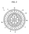
- FIG. 2 is a cross-sectional view taken along the line A-A in FIG. 1.
- FIG. 3A is a plan view looking in the direction B in FIG. 1.
- FIG. 3B is a cross-sectional view taken along the line D-D in FIG. 3A.
- the fuel pump unit 1 is positioned such that it is immersed in fuel inside a fuel tank (not shown) of a vehicle or motorcycle or the like, and takes in fuel that is in the fuel tank via an intake aperture 3a, and feeds it via a discharge aperture 11a to a fuel injection section.
- the fuel pump unit 1 has a pump section P that is mounted on a base bracket 2 (i.e., a bracket member), a motor section M, and a filtration section F.
- the fuel pump unit 1 also has a substantially columnar-shaped external configuration that is enclosed by a pump housing PC that is formed by an inlet cover 3, a pump unit casing 15, and an outlet cover 11.
- the fuel pump unit 1 is represented such that a motor shaft 8a (i.e., a rotation shaft) of the pump section P extends in a vertical direction, and such that the intake aperture 3a is positioned below the fuel pump unit 1, while the discharge aperture 11a is positioned above the fuel pump unit 1.
- Relative positions in the axial direction of the fuel pump 1 are referred to simply as the upper side and lower side.
- positions and directions are represented on the basis of an assembly layout such as that shown in FIG. 1.
- the actual configurational attitude is not limited to this type of attitude.
- the entire fuel pump unit 1 may also be appropriately positioned sloping away from a vertical direction.
- the base bracket 2 is provided with a circular plate shaped plate section 2A that is positioned in a horizontal direction.
- a motor housing mounting section 2b i.e., a mounting section
- a fuel guide groove 2f (see FIG. 3B) are provided on a motor section supporting surface 2c, which is a top surface of the plate shaped section 2A.
- a pump casing groove 2e is provided on a pump section supporting surface 2d, which is a bottom surface of the plate shaped section 2A.
- a bearing section 2a that holds a shaft in an orthogonal direction relative to the plate shaped section 2A such that the shaft is able to rotate is provided at a central section of the plate shaped section 2A.
- a fuel guide hole 2g (see FIG. 3B) is provided between the fuel guide groove 2f and the pump casing groove 2e such that it penetrates both.
- the motor housing mounting section 2b is a wall shaped section that is provided in a substantially cylindrical shape extending vertically upwards from the plate shaped section 2A and substantially coaxially with the center of the plate shaped section 2A.
- a motor housing 6, which is described below, is able to be fitted in an axial direction to an exterior of the motor housing mounting section 2b.
- the pump casing groove 2e is shaped as a circular arc on a cross-section in the radial direction of the plate shaped section 2A, and is provided so as to form a C shape within the pump section supporting surface 2d running along an outer peripheral section of an impeller 5, which is described below.
- a section from a casing groove start end section 3S that is provided at a position that overlaps the intake aperture 3a in the axial direction to a casing groove terminal end section 3E, which is the terminal end of the C shape, is provided at a position so as to substantially overlap the pump casing groove 3c shown in the drawing.
- the radius of the C shape is larger than the outer radius of the motor housing 6.
- the fuel guide hole 2g is a through hole that penetrates from the pump casing 2e to the motor section supporting surface 2c side of the casing groove terminal end section 3E. Accordingly, as is shown in FIG. 3B, the upper aperture of the fuel guide hole 2g is positioned on an outer side in the radial direction of the motor housing 6.
- the fuel guide groove 2f is a groove that is provided in a horizontal direction from the aperture section of the fuel guide hole 2g towards an inner radial side of the plate shaped section 2A.
- the fuel guide groove 2f intersects the motor housing mounting section 2b in a radial direction extending to the inner radial side of the motor housing mounting section 2b so as to terminate before the bearing section 2a.
- the bearing section 2a may be any bearing provided that it is able to radially support a rotation shaft, and various radial slide bearings can be preferably used. In particular, bearings whose structure and material enable a lubrication effect to be obtained as a result of fuel infiltrating gaps in the bearing may be used.
- the bearing section 2a may fix a bearing that is formed as a separate member, or may be formed in the plate shaped section 2A itself.
- the pump P is provided with an impeller 5 that is rotatably provided along the pump section supporting surface 2d, and with a space for pressure feeding fuel that is formed in the pump casing groove 2e and the pump casing groove 3c (described below) and the like and at the periphery of the impeller 5 by covering the impeller 5 from below using the inlet cover 3.
- the inlet cover 3 is fixed to the base bracket 2 by a pump unit casing 15 (described below).
- the impeller 5 is formed by a circular plate shaped member that has a shaft hole in its center for fitting the rotation shaft.
- a large number of blades 5a having a suitable airfoil shape that extend vertically for a predetermined length in a radial direction and that are positioned at a predetermined spacing in a circumferential direction are provided at outer circumferential sections of the circular plate.
- the length of the blades 5a in the radial direction is appropriately set to correspond to the width of the radial direction cross section of the pump casing groove 2e.
- the inlet cover 3 is provided with a sealing surface 3e on an outer circumferential side of the top surface thereof that can be placed tightly against the pump section supporting surface 2d.
- a pump casing section 3b which is a concave section that houses the outer circumferential side surfaces and bottom surfaces of the impeller 5 so that each one is a slight distance apart is provided at an inner side in the radial direction of the sealing surface 3e.
- An intake aperture 3a is provided at a bottom surface of the inlet cover 3 so as to open up directly below outer an circumferential section of the impeller 5.
- the pump casing groove 3c which is a C shaped groove having substantially the same shape as the pump casing groove 2e, is formed at a bottom section of the pump casing section 3b from the casing groove start end section 3S to the casing groove terminal end section 3E.
- a thrust bearing 4 that supports a rotation shaft such that it can rotate in a thrust direction is provided at a center section of the pump casing section 3b.
- the thrust bearing 4 may be any type of material and have any type of configuration provided that it has suitable slide properties when immersed in fuel.
- the pump section P is structured as is described above.
- the impeller 5 rotates in the direction indicated by the arrow in FIG. 3A (i.e., clockwise in FIG. 3A)
- fuel is drawn in from the intake aperture 3a, and fuel inside the pump casing grooves 2e and 3c is raised in pressure between the casing groove start end section 3S and the casing groove terminal end section 3E by the blades 5a, so that it can be fed to the fuel guide hole 2g.
- This type of pump P may employ a variety of known pump structures that are known by names such as, for example, centrifugal pumps, volute pumps, and regenerative pumps.
- the motor section M is provided with a motor rotor 8, field magnets 7, a motor housing 6, and a brush holder 9 (i.e., a cap member). These members form an inner rotor type of DC motor with an attached brush.
- the motor rotor 8 is provided with an armature 8b having a predetermined pole in a center section of a motor shaft 8a, and is also provided with a commutator 8c at a top end side of the motor shaft 8a that has a brush contact surface in a radial direction. (In FIG. 2, because the drawing is schematic, details such as the winding coil of the commutator 8b have been omitted).
- a shaft distal end section that is fixed in a shaft hole in the center of the impeller 5 and protrudes downwards from the impeller 5 is supported in the axial direction by the thrust bearing 4.
- the motor housing 6 is a circular cylinder member having apertures at both ends thereof, the motor housing 6 is externally fitted from above in the axial direction to the motor housing mounting section 2b, and is mounted vertically above the motor section supporting surface 2c.
- the motor housing 6 can be formed, for example, by cutting a steel pipe or the like.
- the field magnets 7 have a partial cylindrical shape whose outer circumferential surface can be placed tightly against an inner surface of the motor housing 6. As is shown in FIG 2, the field magnets 7 are formed by two permanent magnets that face each other in the radial direction.
- the inner circumferential surface of each field magnet 7 has an inner diameter that forms a predetermined gap between itself and an outer circumferential surface of the motor rotor 8.
- Two field magnets 7 are placed adjacent to each other in the circumferential direction via a spacer 16, and are thrust in the circumferential direction by a pressing member 17 that faces the spacer 16 in the radial direction. As a result, they are fixed in predetermined positions relative to the motor housing 6.
- the spacer 16 and the pressing member 17 are both formed so as to be thinner in the radial direction than the permanent magnets 7. Because of this, between the field magnets 7 in the circumferential direction, a gap is formed that is continuous in the axial direction and that is larger than the gap in the radial direction between the field magnets 7 and the motor rotor 8. This structure enables fuel to flow easily through the motor housing 6 in the axial direction.
- the brush holder 9 is a member that is fitted by being inserted into the inner circumferential surface of a top end section of the motor housing 6 so as to cover the motor rotor 8 from above.
- the brush holder 9 is formed by fixing a bearing section 9a that is formed by a penetrating cylindrical hole that supports a motor shaft 8a in a radial direction, and a brush 10 that supplies current to the motor rotor 8 by coming into contact with the commutator 8c from the outer side in the radial direction.
- the brush holder 9 After being fitted, the brush holder 9 is fixed to the motor housing 6 using a suitable apparatus such that no deformation occurs that may cause a malfunction in the bearing section 9a.
- the brush holder 9 may be fixed by providing a suitable fixing member. This might involve fitting the brush holder using a form that does not allow the brush holder to be withdrawn such as a snap-fit, or making the fitting a screw tight fit by using pressure insertion.
- bearing section 9a is open in the axial direction, when the brush holder 9 is assembled by being inserted into the motor housing 6, it is possible to view the shaft end section of the motor shaft 8b from the direction of insertion, enabling the ease of assembly to be improved.
- FIGS. 4A, 4B, 4C, and 4D are an explanatory plan view and an explanatory front view for describing the brush holder 9 according to the present embodiment, while FIGS. 4C and 4D are cross-sectional views taken along the lines G-G and H-H respectively in FIG. 4A.
- the brush holder 9 is provided with a concave hole-shaped commutator housing section 9b for housing the commutator 8c.
- the commutator housing section 9b is positioned above a center section of a flange section 9c that extends in a horizontal direction and covers the aperture section of the motor housing 6.
- the brush holder 9 is also provided with a fitting section 9e shaped like a cylindrical wall that is positioned at a bottom surface in the circumferential direction of the same flange section 9c and fits inside the motor housing 6.
- Penetrating holes 9d are provided at two locations on the flange section 9c on an inner circumferential side of the fitting section 9e.
- the penetrating holes 9d are provided in order that the internal pressure generated by the fuel inside the motor section M is maintained at a constant equilibrium with the external pressure from the fuel in outer circumferential sections of the motor section M.
- a wiring anchoring section 9g is formed by protrusions and grooves and the like that are provided in order to anchor electrical wiring of the brush 10.
- the material of the brush holder 9 it is possible to employ a synthetic resin molded product having an appropriate electrical resistance and having sufficient slidability to allow the bearing section to be formed.
- a synthetic resin molded product By using a synthetic resin molded product, it is possible to easily form these additional shapes. Even if the fitting section 9e is deformed by pressure insertion, it is difficult for that deformation to reach as far as the bearing section 9a.
- the filtration section F is formed by placing a filter member 12, whose outer configuration is shaped substantially as a circular cylinder, in a toroidal chamber enclosed by the pump unit casing 15 that is shaped like a circular cylinder and extends substantially coaxially with the motor section M so as to enclose an outer circumference thereof, the base bracket 2 that is fixed below the pump unit casing bracket, the motor housing 6, and an outlet cover 11 (described below).
- the pump unit casing 15 has a top fixing section 15a and a bottom fixing section 15b that have a circular cylinder shape and are formed at a top and bottom aperture end sections of the pump unit casing 15.
- the inside diameter of each fixing section is slightly enlarged, and an inner surface step is formed at a predetermined position in the axial direction.
- the base bracket 2 is inserted into the bottom fixing section 15b from below the pump unit casing 15 and is anchored. When the inlet cover 3 is inserted from below, by riveting the bottom fixing section 15b to the outer circumferential section of the inlet cover 3, the base bracket 2 is fixed to the pump unit casing 15.
- End sections in a vertical direction of the filter member 12 are anchored respectively to a top sealing member 14 and a bottom sealing member 13 and are fixed in position with a gap provided in the radial direction relative to the motor housing 6 and the pump unit casing 15.
- This gap in the radial direction forms a flow path facing the filter member 12 that allows fuel to move in an axial direction and circumferential direction.
- the filter member 12 may be any material and configuration provided that the filter can be placed inside the toroidal chamber and can filter fuel to the necessary degree of cleanliness.
- the filter can be placed inside the toroidal chamber and can filter fuel to the necessary degree of cleanliness.
- net type, fabric type, porous type, and granular type of filters that can filter dirt, such as bearing abrasion powder, which is of a size that may cause harmful effects to the operation of latter stage fuel injection valves may be employed.
- the bottom sealing member 13 is formed by toroidal plate-shaped packing, and is positioned so as to be placed tightly against the bottom surface of the motor section supporting surface 2c, and is also positioned such that an outer circumference and inner circumference of the toroidal section of the bottom sealing member 13 are in contact in a circumferential direction respectively with the inner circumferential surface of the pump unit casing 15 and the outer circumferential surface of the motor housing 6.
- the bottom surface side of the toroidal chamber is sealed, and is kept in a state whereby fuel cannot directly enter or exit the toroidal chamber from the pump section P.
- the bottom sealing member 13 is formed as a shielding member that covers the top of the fuel guide groove 2f.
- the fuel guide hole 2g and the fuel guide groove 2f form a connecting flow path (i.e., a pump side connecting flow path) that connects the pump section P with the motor section M.
- the top sealing member 14 is formed by the same packing as the bottom sealing member 13 and an inner circumference of the toroidal section thereof is fixed to the outlet cover 11.
- FIG. 5A is a top surface explanatory view for describing the outlet cover 11.
- FIG. 5B is a cross-sectional view taken along the line J-J in FIG. 5A.
- the outlet cover 11 is circular when viewed from above.
- the outlet cover 11 is covered by a plate member except for the discharge aperture 11 a that is provided in the vicinity of the outer circumference of the outlet cover 11.
- an outer circumference wall 11b shaped like a circular cylinder wall is provided below the outer circumference of the plate member.
- a partition wall 11d shaped like a circular cylinder wall is provided coaxially in the same direction as the outer circumference wall 11b at an inner side in the radial direction of the outer circumference wall 11b.
- An outer circumference groove 11c is formed between the partition wall 11d and the outer circumference wall 11b in the radial direction.
- the size of the outer circumference groove 11c is such that when the top sealing member 14 is externally fitted onto the partition wall 11d, the outer circumference of the top sealing member 14 faces the inner circumference of the partition wall 11d with an appropriate gap being provided.
- a brush guide housing section 11e that is formed in the shape of a concave hole by the partition wall 11d and the top plate member is formed with a size and configuration that allows it to house inside itself the top surface side of the brush holder 9 that is above the flange section 9c.
- the outlet cover 11 does not have any section requiring precise dimensions such as the bearing section and the like, it may be deformed by internal pressure so long as it provides sufficient strength against the internal pressure of the filtration section F. Accordingly, a synthetic resin molded component can be preferably used for the outlet cover 11. If a synthetic resin molded component is used, then even if the brush holder 9 has a complex configuration, the outlet cover 11 can easily be formed in a shape that provides a suitable gap to match the complex configuration. A member such as an anchor hook 11f used for mounting on the fuel tank can be easily provided integrally.
- the inner circumferential section of the top sealing member 14 is fixed in the circumferential direction and upward direction to an outer circumferential section of the partition wall 11d.
- the outer circumferential wall 11b is fitted inside the top fixing section 15a that is provided at a top end section of the pump unit casing 15, and is fixed to the top fixing section 15a by riveting.
- a gap 19 is formed between the outer circumferential section of the top sealing member 14 and the inner circumferential surface of the outer circumferential wall 11b that allows fuel that has passed through the filter member 12 to flow to the discharge aperture 11a.
- the top surface side of the brush holder 9 has a suitable gap between itself and the inner surface of the brush guide housing section 11e.
- a continuous gap is thus formed that allows fuel to move smoothly in the radial direction and the circumferential direction.
- the partition wall 11d and the top sealing member 14 are placed so as to open up a gap 18 in the radial direction with the flange section 9c of the brush holder 9.
- a filtration side connecting flow path f2 that connects the interior of the pump section P with the filtration section F is formed by the through hole 9d and the gap between the brush holder 9 and the inner surface of the outlet cover 11.
- FIG. 6 is a partial enlarged cross-sectional view for describing a fuel flow path inside the fuel pump unit 1.
- FIG. 7 is a schematic explanatory view looking in the direction C in FIG. 1 for describing a connecting flow path f2 on a filtration side.
- the fuel pump unit 1 of the present embodiment when the motor section M is driven so that the impeller 5 is rotated with the fuel pump unit 1 immersed in a fuel tank or the like, fuel is taken in from the intake aperture 3a and is transported while the pressure thereof is raised inside the pump casing grooves 2e and 3c. As is shown by the arrows in the drawings, the fuel, which is at increased pressure, is fed from the pump section P to the motor section M through the pump side connecting flow path f1 that is formed by the fuel guide hole 2g, the fuel guide groove 2f, and the bottom sealing member 13.
- the flow of fuel inside the pump section P moves towards the bearing section 2a and flows so as to lubricate the bearing section 2a. It then flows forward while covering the motor rotor 8 and field magnets 7 either between the motor rotor 8 and the field magnets 7 or through the gap in the circumferential direction of the field magnets 7 and 7. Accordingly, a flow that detours around the vicinity of the commutator 8c is generated.
- Either flow enables fuel to be fed from the motor section M to the filtration section F by the filtration side connecting flow path f2. Not only fuel, but heat and dirt are also transported. Therefore, the motor rotor 8 and the field magnets 7 are cooled, and abrasion powder generated by the bearing sections 2a and 9a and by the commutator 8c is removed. At this time, because the filtration side connecting flow path f2 is provided so as to be connected to the gap in the radial direction above the brush holder 9, a flow of fuel is also generated in the vicinity of the area above the bearing section 9a, so that cleaning, lubrication, and cooling of the bearing section 9a can be performed efficiently.
- the fuel pump unit 11 of the present embodiment filters fuel that it discharges, clean fuel can be supplied, for example, to the fuel injection pump in latter stages.
- the filtration side connecting flow path f2 is provided at one end section (the top end section) in the axial direction of the filter member 12, blockages caused by fouling of the filter member 12 progress from the one end section side and the flow path is detoured corresponding to these blockages.
- the filter surface area is gradually narrowed, the filter surface forming the actual flow path is easily able to maintain its cleanness, and compared with when the entire filter surface is blocked uniformly, the performance such as the discharge rate and pump load and the like are stable for a considerable length of time.
- the filtration section F and the motor section M are connected only by the filtration side connecting flow path f2, and the majority thereof is separated by the motor housing 6 that covers the motor rotor 8. Therefore, the rotating flow of the fuel created by the motor rotor 8 is violent inside the motor section M, but extremely gentle inside the filtration section F. As a result, it is difficult for dirt and the like adhering to the filter member 12 to be affected by the rotation of the motor rotor 8. Namely, compared with when the rotor is rotating in the vicinity of the filter, it is extremely rare for dirt from the filter member 12 to become detached and float freely in the fuel. Accordingly, there is no reverse flow of dirt to the motor section M.
- the interior of the motor section M is kept comparatively clean, it is possible to reduce faults such as dirt becoming blocked in the bearing gaps of the bearing sections 2a and 9a, and to thereby improve reliability.
- the fuel pump unit 1 is typically used in a placement attitude such as that in the above explanation. In this case, because dirt inside the filtration section F is precipitated out by its own weight, reverse flow becomes even more difficult.
- a pump section P is provided that has an impeller 5 in which blades 5a are provided to cover a diameter that is larger than the outer diameter of the motor section M, and the outer circumferential section of the pump section P and the inner section of the motor section M are connected by the pump side connecting flow path f1. Therefore, even at a comparatively low rotation speed, it is possible to raise the circumferential speed of the impeller 5 and raise the pump pressure, and to thereby make the structure of the motor section M smaller. It is also possible to reduce the noise when the pump is in operation.
- filtration section F is placed above the pump section P that protrudes to the outer side of the motor section M, space inside the columnar shaped interior can be utilized effectively and a compact structure can be achieved.
- the pump side connecting flow path f1 arrives at the motor section M via the fuel guide groove 2f that forms a horizontally bent flow path from the fuel guide hole 2g that extends vertically upward. Accordingly, even if dirt inside the motor section M falls due to its own gravity, it falls onto the exit aperture of the fuel guide groove 2f. The force that propels the dirt in a horizontal direction along the fuel guide groove 2f does not work from the motor section M side, but, in contrast, highly pressured fuel is pressure fed from the pump section P side. Therefore, the dirt does not return to the blades 5a. Accordingly, even if the pump section P is placed vertically underneath, it is still possible to prevent dirt from reverse flowing to the blades 5a and damaging the pump section P. Thus an improvement in reliability is achieved.
- FIG. 8 is a schematic cross-sectional view in an axial direction for describing showing the fuel pump unit 50 according to a modified example of the present embodiment.
- the fuel pump unit 50 of this modified example uses a commutator 80c instead of the commutator 8c of the fuel pump unit 1, and consequently uses a brush holder 22 and an outlet cover 23 instead of the brush holder 9 and the outlet cover 11.
- a bottom sealing member 20 and a top sealing member 21, which form the modified example, are used instead of the bottom sealing member 13 and top sealing member 14.
- the remainder of the structure is the same as the sections described above. Only those sections that are different from those above are described below.
- the commutator 80c is a type of commutator that abuts against the brush 10 in the axial direction. Therefore, the brush holder 22 has a configuration that allows it to hold the brush 10 in the axial direction.
- FIG. 9A is a top explanatory view for describing the brush holder 22.
- FIG. 9B is a cross-sectional view taken along the line L-L in FIG. 9A.
- FIG. 9C is a rear explanatory view.
- FIG. 9D is a cross-sectional view taken along the line N-N in FIG. 9A.
- the brush holder 22 is provided with a cylindrically shaped fitting section 22e that fits in an inner circumferential section of the motor housing 6 at a bottom side of a circular top surface section 22h. Respective inner surfaces thereof form a commutator housing section 22b which is a concave hole capable of providing a gap to store the commutator 80c.
- a flange section 22c for providing an anchor with the end section of the motor housing 6 is provided in the central section in the axial direction of the fitting section 22e.
- Brush fixing sections 22f that are formed by through holes running in the axial direction are provided in two locations on an upper side of the top surface section 22h.
- a bearing section 22a that supports a motor shaft 8a is provided in a center section of the top surface section 22h.
- a shaft pressing member is constructed on a top end section thereof so as to extend across in the radial direction.
- On the left and right sides in the radial direction a half moon shaped gap is provided.
- a wiring anchor section 22g that anchors electrical wiring of the brush is provided on a top surface section 22h at a side of the bearing section 22a.
- a through hole 22d that is notched in the top surface section 22h and in the upper side section of the flange section 22c is provided at a section of an outer circumferential section of the top surface section 22h.
- the fitting section 22e is fitted into the top end section of the motor housing 6, and is anchored to an end section in the axial direction of the motor housing 6 by the flange section 22e so as to cover the top section of the motor section M.
- a brush 10 is inserted from above into the brush fixing section 22f.
- the outlet cover 23 is a cap member that is provided with a discharge aperture 11a on a top surface side thereof in the same way as the outlet cover 11. It is also provided with an outer circumferential wall in the same way and is fixed to the pump unit casing 15.
- FIGS. 10A, 10B, and 10C are a rear explanatory view, a cross-sectional view taken along the line Q-Q, and a top explanatory view showing an outlet cover 23 according to this modified example.
- a brush guide housing section 23e that provides a gap to house a top surface side of the brush holder 22 is formed by the circular cylinder wall-shaped partition wall 23d that forms the outer circumferential groove 11c.
- a brush pressing section 23h formed by a cylindrical conduit that is used for inserting a pressing spring 25 in the axial direction so as to correspond to the placement position of the brush 10 is mounted on a top surface of the brush guide housing section 23e.
- the pressing springs 25 are provided in order to press the brush 10 against the commutator 80c at a predetermined pressure, and are compressed downwards by spring pressing members 26 that are inserted from above the brush pressing section 23h.
- the aperture of the brush pressing section 23h is sealed by the spring pressing members 26, and the only aperture in the top surface of the outlet cover 23 is the discharge aperture 11 a.
- the brush holder 22 is urged from the outlet cover 23 in the axial direction by the pressing force of the pressing spring 25, so that a gap extending in the radial direction and the circumferential direction is provided between the top surface of the brush holder 22 and the inner surface of the brush guide housing section 23e.
- FIG. 11 is a schematic explanatory view looking in the direction K in FIG. 8. As is shown in FIG. 11, fuel flows through this gap from the through hole 22d, and a filtration side connecting flow path f2 is formed from the gap 18 to the filtration section F.
- the bottom sealing member 20 and the top sealing member 21 are examples of metal plate members formed by rings whose cross section in the axial direction is substantially U shaped. According to this type of configuration, they can be formed as lightweight and low cost members.
- the bottom sealing member 20 is mounted to the bottom section of the toroidal chamber, because it is possible to assemble the bottom sealing member 20 in the toroidal chamber by press insertion utilizing the springiness of the side surfaces of the U shape, the ease of assembly is improved.
- the brush holder 22 is pressed via the pressing spring 25, however, because the pressing direction is an axial direction, no failures such as the bearing section 22a deforming occur.
- the filtration side connecting flow path f2 has a working effect in the same way as the fuel pump unit 1, however, in this modified example, in particular, because the through hole 22d is provided at substantially the same height as the brushing contact section of the brushes 10, dirt generated by the brushing contact of the brushes is scattered in a horizontal direction by centrifugal force, and in that state is reliably carried away via the through hole 22d, so that the cleanliness of the motor section M is further improved.
- outlet cover and the cap member are not in contact with each other, and of when they are in contact via a spring.
- the outlet cover and the cap member may be allowed to come into contact due to pressure variations inside the pump housing provided that the bearing section and the like that are provided in the cap member are not deformed above a permissible value.
- the outlet cover is formed by a material having a low rigidity, then it is possible to provide protrusions and partition walls and the like in order to secure a gap from the cap member so as to prevent unevenness in the gap caused by bending and the like of the component.
- the bearing section does not cause excessive deformation, then when the pump is being operated, the outlet cover receives pressure internally and expands. Consequently, it deforms so as to move away from the protrusions and partition walls and enlarge the gap, and the bearing deformation does not increase any more than that.
- a through hole is provided in the cap member in order to equalize the internal pressures of the motor section and the toroidal chamber and the fuel is allowed to circulate more freely above the bearing section, however, a through hole may also be provided in the motor housing in the vicinity of the cap member.
- the present invention provides a fuel pump unit that is extremely easy to assemble, and that provides improved reliability without the motor section being deformed by internal pressure.
Landscapes
- Engineering & Computer Science (AREA)
- Chemical & Material Sciences (AREA)
- Combustion & Propulsion (AREA)
- Mechanical Engineering (AREA)
- General Engineering & Computer Science (AREA)
- Structures Of Non-Positive Displacement Pumps (AREA)
Abstract
Description
- The present invention relates to a fuel pump unit.
- Conventionally, a fluid pump is known in which a fluid pump unit that is provided with an intake aperture and in which a pump and a drive motor are formed integrally is immersed in a fluid and discharges the fluid to the outside. This type of fluid pump is widely used to discharge fluid from a fluid tank. For example, an in-tank type of fuel pump such as this is also used in fuel tanks of motorcycles and the like. Among such fuel pumps, a fuel pump that is highly reliable and that can be mounted in a small sized fuel tank and can rapidly supply clean fuel that does not cause a fuel injection valve to become blocked is demanded. Therefore, a fuel pump exists that causes fuel to infiltrate interior sections thereof enabling the motor to be cooled and movable parts to be lubricated so as to improve reliability, and that is provided with a barrier filter that removes dirt generated by the movable parts in front of the discharge aperture, and in which the barrier filter is formed integrally with the pump section and motor section so as to achieve a reduction in size.
- For example, in Japanese Unexamined Patent Application, First Publication No. 2002-285930 (Document 1), there is disclosed a motor type of fuel pump that is provided with a pump chamber and a motor chamber, and that is provided with a filter that is positioned upstream of the discharge path inside the motor chamber so as to cover an outer circumference of the motor.
- Pumps are also known that do not infiltrate fuel in the motor, but feed fuel directly using a pump.
- In Japanese Unexamined Patent Application, First Publication No. Hei 11-230076 (Document 2), there is disclosed a fuel pressure feed unit that is provided with a toroidal chamber in which an electric motor is housed in a central chamber, and in which a fuel main filter that is partitioned by a partition wall of a casing is positioned at an outer periphery of the electric motor, and that discharges fuel after feeding it to the toroidal chamber using a pump.
- However, the following problems exist in conventional fuel pumps such as those described above.
- In the technology described in
Document 1, the rotation shaft of an outer rotor that drives an impeller of the pump to rotate is provided inside a motor chamber and is supported by a bearing that is provided in a lower fitting section and by a bearing that is positioned inside a stator provided in a bearing holding cover. The bearing holding cover is fixed by another end thereof being riveted to a pump case. - In this type of structure, when the bearing holding cover is being riveted, the bearing holding cover tends to deform so that the gap between the bearing and the rotation shaft changes easily. Therefore, the problem arises that unevenness tends to occur in the rotation load caused by manufacturing errors and the like. If there is a large rotation load, the bearing is easily cut away and, as a result of dirt such as shavings from this cutting increasing, the reliability of the apparatus deteriorates.
- Even if the apparatus can be assembled with few manufacturing errors, because a bearing supporting cover supports the internal pressure in the motor chamber, the bearing supporting cover is deformed by internal pressure when the pump is in operation. In particular, in a fuel pump of a motorcycle and the like in which rapid fuel injection is required, the discharge pressure of the fuel is also large, and as a result, the bearing gap is narrowed and the rotation load is increased, which consequently causes lockups to occur.
- If the bearing support cover is fitted to the rotation shaft via a bearing, the structure is such that it is not possible to view the rotation shaft, thereby creating the problem that assembly is difficult.
- The rotation shaft of the outer rotor that drives the impeller of the pump to rotate is positioned inside the motor chamber and is supported by the bearing that is provided in the lower fitting section and by the bearing that is positioned inside the stator provided in the bearing holding cover. A filter is provided integrally inside the motor chamber in the same way so as to surround the outer circumference of the rotor yoke of the outer rotor.
- Accordingly, fuel is unable to flow easily to the bearing that is provided inside the stator and is covered by the outer rotor, so that dirt such as abrasion powder and the like created by the rotation of the motor is easily accumulated.
- In the motor chamber, because a fuel flow is generated constantly in a peripheral direction on the filter surface as the outer rotor rotates, the prosection of dirt absorbed in the filter that falls off once again and meanders around the interior of the motor chamber increases. As a result, it is difficult to keep the interior of the motor clean, thereby causing the bearing to be damaged and causing the fuel pump to break down when there is a reverse flow of dirt inside the pump chamber.
- The pump discharge path that is provided in a vertical direction directly above the impeller must be positioned on an inner side of the filter in the motor chamber. Therefore, if the outer diameter of the pump is increased in order to speed up the circumferential speed, the position of the filter needs to be moved towards the outer circumferential side so that the size of the fuel pump is increased.
- In contrast, in the technology of
Document 2, because the electric motor is positioned in a central chamber partitioned by a partition wall of the casing, although abrasion powder from the electric motor does not become mixed into the fuel, and it is possible to enlarge the outer diameter of the pump impeller while keeping the outer diameter of the fuel pump small, the problem remains that cleaning and lubrication of the electric motor is still not possible. - If a small amount of fuel infiltrates into the central chamber and is turned into a gas, the possibility exists that the fuel will be ignited by an electrical discharge or the like.
- The fuel pump unit according to the present invention is a fuel pump unit in which a pump section, which takes in and pressure feeds fuel, and a motor section, which has a motor rotor one end of whose rotation shaft is fixed to the pump section, are provided inside a pump housing having an intake aperture and a discharge aperture, and in which a fuel flow path is formed inside the motor section. One end side of the rotation shaft of the motor rotor is rotatably supported by a bracket member, a motor housing that covers the motor rotor in the circumferential direction is mounted to the bracket member, and a bearing section that rotatably supports another end of the rotation shaft is formed in the motor housing. As a result, the motor section is made to be supported by the bracket member and not by the pump housing.
- According to this invention, the gap in the bearing section can be properly secured without any deformation occurring in the motor section when the motor section is mounted to the pump housing. The pump section and motor housing can be assembled in separate steps.
- It is also possible for a gap to be formed in an axial direction and circumferential direction of the motor section between the motor section and the pump housing, and for the fuel flow path to be formed by this gap.
- In this case, a fuel flow is formed at least along the bearing section provided at an outer circumferential section of the motor housing and at the distal end section in the mounting direction thereof.
- It is also possible for a mounting section that protrudes in the shape of a wall to be provided on a motor rotor side of the bracket member, and for the motor housing to be mounted so as to be fitted to the mounting section.
- In this case, even if bending moment from the motor section acts on the bracket member, it is possible to suppress deformation of the plate-shaped section. Assembly of the motor housing is thus simplified.
- It is also possible for a through hole running in an axial direction to be provided in the bearing section that enables a shaft end section of the rotation shaft of the motor rotor to be viewed from the bearing section mounting direction at least at a time when the motor section is assembled by fitting the other end of the rotation shaft in the bearing section.
- In this case, because it is possible using the through hole provided in the bearing section to view the shaft end section of the rotation shaft of the motor rotor from the direction from which it is mounted in the bearing section when the motor section is being assembled, assembly is simplified.
- It is also possible for a cap member that substantially covers a distal end side in the mounting direction of the motor housing to be inserted and fitted in the axial direction of the motor housing, and for the bearing section to be provided in the cap member.
- In this case, it is difficult for the bearing section to be deformed during assembly.
- Here, the fitting is not limited solely to stop gap fitting and includes intermediate fitting and tight fitting, provided that there are no deforming effects on the bearing section. Namely, the insertion may also be a press insertion.
- It is also possible for the pump housing to be formed by a cylindrical casing member that extends in an axial direction of the rotation shaft, an inlet cover that has an intake aperture for the fuel and that covers the impeller between itself and the bracket member, and an outlet cover that has a discharge aperture for the fuel and that covers the radial direction of the motor section, and for the inlet cover and the outlet cover to be fixed respectively to both end sections of the casing member.
- In this case, because an inlet cover and outlet cover that require a comparatively complex configuration starting with the intake aperture and discharge aperture are formed as separate members, manufacturing is simplified.
- It is also possible for at least one of the inlet cover and outlet cover to be fixed by riveting to the casing member.
- In this case, the apparatus can be manufactured easily and at low cost.
- It is also possible for the pump section to be formed by placing an impeller having a larger outer diameter than an outer diameter of the motor housing on a rear surface of that side of the bracket member to which the motor housing is mounted, and for the pump section and the motor section to be connected by a pump side connecting flow path that extends from an outer circumferential section of the pump section.
- In this case, even if the motor section has a comparatively small diameter, fuel that is pressure fed by the impeller can be guided to the motor section.
- It is also possible for a toroidal chamber to be provided at an outer circumference of the motor housing, and for a filtration section to be formed by placing a filtration apparatus for the fuel inside the toroidal chamber.
- In this case, the filtration section can be built in while the space that overlaps with the impeller in the radial direction is effectively used.
- It is also possible for the filtration section to be sealed off from the pump section.
- In this case, because the filtration section is sealed off from the pump section, all the fuel flows to the motor section, and there is no flow from the filtration section returning directly to the pump section.
- It is also possible for the pump side connecting flow path to be provided inside the bracket member.
- In this case, a reduction in space can be achieved.
- It is also possible for the pump side connecting flow path to be formed by covering a section of a groove that is formed in a surface of the bracket member with a shielding member that abuts against the bracket member.
- In this case, the pump side connecting flow path can be formed simply.
- It is also possible for the pump side connecting flow path to be provided with a flow path that is located within a plane that is substantially parallel with a rotation plane of the impeller and that travels from a vicinity of an outer circumferential section of the impeller inwards in a radial direction.
- In this case, even if dirt or the like flows from the pump section in the axial direction of the impeller, it is possible to prevent the dirt from reaching a position directly above the outer circumferential section of the pump section in the axial direction thereof.
- It is also possible for the motor section to be formed at one of the bracket members; for the pump section to be formed at another of the bracket members; for a filtration section to be formed as a fuel filtration apparatus at an outer circumference of the motor housing; for a pump side connecting flow path that connects an interior of the pump section to an interior of the motor section to be provided in a vicinity of a mounting section of the bracket member and the motor housing; for a filtration side connecting flow path that connects the motor section and the filtration section to be provided in the motor housing; and for the fuel that is taken in from the intake aperture to flow from the pump section along the pump side connecting flow path and into the motor section, and after the fuel has flowed along the filtration side connecting flow path and into the filtration section for it to be discharged to the discharge aperture.
- In this case, because there is provided a pump side connecting flow path and a filtration side connecting flow path, and fuel that is taken in from the intake aperture flows in sequence through the pump section, motor section, and filtration section to the discharge aperture, dirt such as abrasion powder that is generated from movable sections within the motor section is transported out, together with the fuel, to the filtration section and is filtered, and clean fuel can be discharged from the discharge aperture.
- It is also possible for there to be provided a cap member that is inserted in the axial direction of the motor housing and is fitted therein and that substantially covers a distal end side in the mounting direction of the motor housing, and that also forms the bearing section; and for a gap that is continuous in at least the radial direction of the motor housing to be provided between the cap member and the pump housing, and for a through hole to be provided in a section of the cap member so as to face the gap; and for the filtration side connecting flow path to be formed by the through hole and the gap.
- In this case, because fuel flows via the filtration side connecting flow path from the though hole in the cap member that is provided in the bearing section along a gap that is continuous in at least the radial direction to the filtration section at the outer circumference of the motor housing, a fuel flow path is formed in the vicinity of the bearing section. As a result, dirt such as abrasion powder and the like that is generated by the bearing section is efficiently cleaned and transported to the filtration section.
- It is also possible for the bearing section to be provided with an aperture that faces the filtration side connecting flow path
- In this case, because it is possible for the bearing section to be in contact via the aperture with the fuel flowing along the filtration side connecting flow path, dirt such as abrasion powder and the like that is generated by the bearing section is efficiently cleaned and transported to the filtration section.
- It is also possible for the cap member to be a brush holder in which is placed a brush that is abutted against a commutator that is provided in the motor rotor.
- In this case, because the cap member above which is formed the filtration side connecting flow path is a brush holder, dirt such as abrasion powder created by the contact between the commutator and the brush and the like that is generated by the bearing section is efficiently cleaned and transported to the filtration section.
-
- FIG. 1 is a schematic cross-sectional view in an axial direction showing the fuel pump unit according to the present invention.
- FIG. 2 is a cross-sectional view taken along the line A-A in FIG. 1.
- FIG. 3A is a plan view looking in the direction B in FIG. 1. FIG. 3B is a cross-sectional view taken along the line D-D in FIG. 3A.
- FIG. 4A is a plan view showing the brush holder according to the present invention. FIG. 4B is a frontal view of the same. FIG. 4C is a cross-sectional view taken along the line G-G in FIG. 4A. FIG. 4D is a cross-sectional view taken along the line H-H in FIG. 4A.
- FIG. 5A is a top view showing the outlet cover according to the present invention. FIG. 5B is a cross-sectional view taken along the line J-J in FIG. 5A.
- FIG. 6 is a partial enlarged cross-sectional view for describing a fuel flow path within the fuel pump unit according to the present invention.
- FIG. 7 is a schematic explanatory view looking in the direction C in FIG. 1 for describing a connecting flow path on a filtration side according to the present invention.
- FIG. 8 is a schematic cross-sectional view in an axial direction showing a modified example of the fuel pump unit according to the present invention.
- FIG. 9A is a top view showing the brush holder according to the modified example of the present invention. FIG. 9B is a cross-sectional view taken along the line L-L in FIG. 9A. FIG. 9C is a rear view showing the brush holder according to the present invention. FIG. 9D is a cross-sectional view taken along the line N-N in FIG. 9A.
- FIG. 10A is a rear view showing an outlet cover of the modified example according to the present invention. FIG. 10B is a cross-sectional view taken along the line Q-Q in FIG. 10A. FIG. 10C is a top view showing another outlet cover according to the present invention.
- FIG. 11 is a schematic explanatory view looking in the direction K in FIG. 8.
-
- Preferred embodiments of the present invention will now be described with reference made to the drawings. It is to be understood that the present invention is not limited by the embodiments given below, for example, component elements of these embodiments may be combined together as is appropriate.
- Fig 1 is a schematic cross-sectional view in the axial direction for describing the
fuel pump unit 1 according to an embodiment of the present invention. FIG. 2 is a cross-sectional view taken along the line A-A in FIG. 1. FIG. 3A is a plan view looking in the direction B in FIG. 1. FIG. 3B is a cross-sectional view taken along the line D-D in FIG. 3A. - The
fuel pump unit 1 according to the present embodiment is positioned such that it is immersed in fuel inside a fuel tank (not shown) of a vehicle or motorcycle or the like, and takes in fuel that is in the fuel tank via anintake aperture 3a, and feeds it via adischarge aperture 11a to a fuel injection section. As is shown in FIGS. 1 and 2, thefuel pump unit 1 has a pump section P that is mounted on a base bracket 2 (i.e., a bracket member), a motor section M, and a filtration section F. Thefuel pump unit 1 also has a substantially columnar-shaped external configuration that is enclosed by a pump housing PC that is formed by aninlet cover 3, apump unit casing 15, and anoutlet cover 11. - In order to simplify the description given below, as is shown in FIG. 1, the
fuel pump unit 1 is represented such that amotor shaft 8a (i.e., a rotation shaft) of the pump section P extends in a vertical direction, and such that theintake aperture 3a is positioned below thefuel pump unit 1, while thedischarge aperture 11a is positioned above thefuel pump unit 1. Relative positions in the axial direction of thefuel pump 1 are referred to simply as the upper side and lower side. Moreover, in the description of each component, provided that the upper side (or lower side) of a drawing is not particularly specified, positions and directions are represented on the basis of an assembly layout such as that shown in FIG. 1. - However, the actual configurational attitude is not limited to this type of attitude. For example, the entire
fuel pump unit 1 may also be appropriately positioned sloping away from a vertical direction. - The
base bracket 2 is provided with a circular plate shapedplate section 2A that is positioned in a horizontal direction. A motorhousing mounting section 2b (i.e., a mounting section) and afuel guide groove 2f (see FIG. 3B) are provided on a motorsection supporting surface 2c, which is a top surface of the plate shapedsection 2A. Apump casing groove 2e is provided on a pumpsection supporting surface 2d, which is a bottom surface of the plate shapedsection 2A. - A
bearing section 2a that holds a shaft in an orthogonal direction relative to the plate shapedsection 2A such that the shaft is able to rotate is provided at a central section of the plate shapedsection 2A. Afuel guide hole 2g (see FIG. 3B) is provided between thefuel guide groove 2f and thepump casing groove 2e such that it penetrates both. - The motor
housing mounting section 2b is a wall shaped section that is provided in a substantially cylindrical shape extending vertically upwards from the plate shapedsection 2A and substantially coaxially with the center of the plate shapedsection 2A. Amotor housing 6, which is described below, is able to be fitted in an axial direction to an exterior of the motorhousing mounting section 2b. - The
pump casing groove 2e is shaped as a circular arc on a cross-section in the radial direction of the plate shapedsection 2A, and is provided so as to form a C shape within the pumpsection supporting surface 2d running along an outer peripheral section of animpeller 5, which is described below. As is shown in FIG. 3A, a section from a casing groove startend section 3S that is provided at a position that overlaps theintake aperture 3a in the axial direction to a casing grooveterminal end section 3E, which is the terminal end of the C shape, is provided at a position so as to substantially overlap thepump casing groove 3c shown in the drawing. The radius of the C shape is larger than the outer radius of themotor housing 6. - The
fuel guide hole 2g is a through hole that penetrates from thepump casing 2e to the motorsection supporting surface 2c side of the casing grooveterminal end section 3E. Accordingly, as is shown in FIG. 3B, the upper aperture of thefuel guide hole 2g is positioned on an outer side in the radial direction of themotor housing 6. - The
fuel guide groove 2f is a groove that is provided in a horizontal direction from the aperture section of thefuel guide hole 2g towards an inner radial side of the plate shapedsection 2A. Thefuel guide groove 2f intersects the motorhousing mounting section 2b in a radial direction extending to the inner radial side of the motorhousing mounting section 2b so as to terminate before thebearing section 2a. - The
bearing section 2a may be any bearing provided that it is able to radially support a rotation shaft, and various radial slide bearings can be preferably used. In particular, bearings whose structure and material enable a lubrication effect to be obtained as a result of fuel infiltrating gaps in the bearing may be used. Thebearing section 2a may fix a bearing that is formed as a separate member, or may be formed in the plate shapedsection 2A itself. - The pump P is provided with an
impeller 5 that is rotatably provided along the pumpsection supporting surface 2d, and with a space for pressure feeding fuel that is formed in thepump casing groove 2e and thepump casing groove 3c (described below) and the like and at the periphery of theimpeller 5 by covering theimpeller 5 from below using theinlet cover 3. Theinlet cover 3 is fixed to thebase bracket 2 by a pump unit casing 15 (described below). - The
impeller 5 is formed by a circular plate shaped member that has a shaft hole in its center for fitting the rotation shaft. A large number ofblades 5a having a suitable airfoil shape that extend vertically for a predetermined length in a radial direction and that are positioned at a predetermined spacing in a circumferential direction are provided at outer circumferential sections of the circular plate. The length of theblades 5a in the radial direction is appropriately set to correspond to the width of the radial direction cross section of thepump casing groove 2e. - The
inlet cover 3 is provided with a sealingsurface 3e on an outer circumferential side of the top surface thereof that can be placed tightly against the pumpsection supporting surface 2d. Apump casing section 3b, which is a concave section that houses the outer circumferential side surfaces and bottom surfaces of theimpeller 5 so that each one is a slight distance apart is provided at an inner side in the radial direction of the sealingsurface 3e. Anintake aperture 3a is provided at a bottom surface of theinlet cover 3 so as to open up directly below outer an circumferential section of theimpeller 5. - The
pump casing groove 3c, which is a C shaped groove having substantially the same shape as thepump casing groove 2e, is formed at a bottom section of thepump casing section 3b from the casing groove startend section 3S to the casing grooveterminal end section 3E. - A thrust bearing 4 that supports a rotation shaft such that it can rotate in a thrust direction is provided at a center section of the
pump casing section 3b. The thrust bearing 4 may be any type of material and have any type of configuration provided that it has suitable slide properties when immersed in fuel. - The pump section P is structured as is described above. When the
impeller 5 rotates in the direction indicated by the arrow in FIG. 3A (i.e., clockwise in FIG. 3A), fuel is drawn in from theintake aperture 3a, and fuel inside thepump casing grooves end section 3S and the casing grooveterminal end section 3E by theblades 5a, so that it can be fed to thefuel guide hole 2g. - This type of pump P may employ a variety of known pump structures that are known by names such as, for example, centrifugal pumps, volute pumps, and regenerative pumps.
- The motor section M is provided with a motor rotor 8,
field magnets 7, amotor housing 6, and a brush holder 9 (i.e., a cap member). These members form an inner rotor type of DC motor with an attached brush. - The motor rotor 8 is provided with an
armature 8b having a predetermined pole in a center section of amotor shaft 8a, and is also provided with acommutator 8c at a top end side of themotor shaft 8a that has a brush contact surface in a radial direction. (In FIG. 2, because the drawing is schematic, details such as the winding coil of thecommutator 8b have been omitted). - On the bottom side of the
armature 8b of themotor shaft 8a, at a distal end section of themotor shaft 8a that is supported in a radial direction by thebearing section 2a and that protrudes at the bottom side of thebearing section 2a, a shaft distal end section that is fixed in a shaft hole in the center of theimpeller 5 and protrudes downwards from theimpeller 5 is supported in the axial direction by the thrust bearing 4. - The
motor housing 6 is a circular cylinder member having apertures at both ends thereof, themotor housing 6 is externally fitted from above in the axial direction to the motorhousing mounting section 2b, and is mounted vertically above the motorsection supporting surface 2c. By mounting themotor housing 6 in this manner, damage such as the bearing gap of thebearing section 2a being deformed and narrowed during assembly is removed, and it is possible to reinforce the external fitting section of the motor rotor 8 so that it is able to receive a considerable bending moment. - The
motor housing 6 can be formed, for example, by cutting a steel pipe or the like. - The
field magnets 7 have a partial cylindrical shape whose outer circumferential surface can be placed tightly against an inner surface of themotor housing 6. As is shown in FIG 2, thefield magnets 7 are formed by two permanent magnets that face each other in the radial direction. The inner circumferential surface of eachfield magnet 7 has an inner diameter that forms a predetermined gap between itself and an outer circumferential surface of the motor rotor 8. Twofield magnets 7 are placed adjacent to each other in the circumferential direction via aspacer 16, and are thrust in the circumferential direction by a pressingmember 17 that faces thespacer 16 in the radial direction. As a result, they are fixed in predetermined positions relative to themotor housing 6. - The
spacer 16 and the pressingmember 17 are both formed so as to be thinner in the radial direction than thepermanent magnets 7. Because of this, between thefield magnets 7 in the circumferential direction, a gap is formed that is continuous in the axial direction and that is larger than the gap in the radial direction between thefield magnets 7 and the motor rotor 8. This structure enables fuel to flow easily through themotor housing 6 in the axial direction. - The
brush holder 9 is a member that is fitted by being inserted into the inner circumferential surface of a top end section of themotor housing 6 so as to cover the motor rotor 8 from above. Thebrush holder 9 is formed by fixing abearing section 9a that is formed by a penetrating cylindrical hole that supports amotor shaft 8a in a radial direction, and abrush 10 that supplies current to the motor rotor 8 by coming into contact with thecommutator 8c from the outer side in the radial direction. - After being fitted, the
brush holder 9 is fixed to themotor housing 6 using a suitable apparatus such that no deformation occurs that may cause a malfunction in thebearing section 9a. For example, thebrush holder 9 may be fixed by providing a suitable fixing member. This might involve fitting the brush holder using a form that does not allow the brush holder to be withdrawn such as a snap-fit, or making the fitting a screw tight fit by using pressure insertion. - Because the
bearing section 9a is open in the axial direction, when thebrush holder 9 is assembled by being inserted into themotor housing 6, it is possible to view the shaft end section of themotor shaft 8b from the direction of insertion, enabling the ease of assembly to be improved. - The
brush holder 9 will now be described in more detail while reference is made to FIGS. 4A, 4B, 4C, and 4D. FIGS. 4A and 4B are an explanatory plan view and an explanatory front view for describing thebrush holder 9 according to the present embodiment, while FIGS. 4C and 4D are cross-sectional views taken along the lines G-G and H-H respectively in FIG. 4A. - The
brush holder 9 is provided with a concave hole-shapedcommutator housing section 9b for housing thecommutator 8c. Thecommutator housing section 9b is positioned above a center section of aflange section 9c that extends in a horizontal direction and covers the aperture section of themotor housing 6. Thebrush holder 9 is also provided with afitting section 9e shaped like a cylindrical wall that is positioned at a bottom surface in the circumferential direction of thesame flange section 9c and fits inside themotor housing 6. - On the side surface side of the
commutator housing section 9b there are providedbrush fixing sections 9f that face in a horizontal direction and into which brushes 10 are inserted and fixed. - Penetrating
holes 9d are provided at two locations on theflange section 9c on an inner circumferential side of thefitting section 9e. The penetratingholes 9d are provided in order that the internal pressure generated by the fuel inside the motor section M is maintained at a constant equilibrium with the external pressure from the fuel in outer circumferential sections of the motor section M. - A
wiring anchoring section 9g is formed by protrusions and grooves and the like that are provided in order to anchor electrical wiring of thebrush 10. - For the material of the
brush holder 9 it is possible to employ a synthetic resin molded product having an appropriate electrical resistance and having sufficient slidability to allow the bearing section to be formed. By using a synthetic resin molded product, it is possible to easily form these additional shapes. Even if thefitting section 9e is deformed by pressure insertion, it is difficult for that deformation to reach as far as thebearing section 9a. - The filtration section F is formed by placing a
filter member 12, whose outer configuration is shaped substantially as a circular cylinder, in a toroidal chamber enclosed by thepump unit casing 15 that is shaped like a circular cylinder and extends substantially coaxially with the motor section M so as to enclose an outer circumference thereof, thebase bracket 2 that is fixed below the pump unit casing bracket, themotor housing 6, and an outlet cover 11 (described below). - The
pump unit casing 15 has atop fixing section 15a and abottom fixing section 15b that have a circular cylinder shape and are formed at a top and bottom aperture end sections of thepump unit casing 15. The inside diameter of each fixing section is slightly enlarged, and an inner surface step is formed at a predetermined position in the axial direction. Thebase bracket 2 is inserted into thebottom fixing section 15b from below thepump unit casing 15 and is anchored. When theinlet cover 3 is inserted from below, by riveting thebottom fixing section 15b to the outer circumferential section of theinlet cover 3, thebase bracket 2 is fixed to thepump unit casing 15. - End sections in a vertical direction of the
filter member 12 are anchored respectively to a top sealingmember 14 and abottom sealing member 13 and are fixed in position with a gap provided in the radial direction relative to themotor housing 6 and thepump unit casing 15. This gap in the radial direction forms a flow path facing thefilter member 12 that allows fuel to move in an axial direction and circumferential direction. - The
filter member 12 may be any material and configuration provided that the filter can be placed inside the toroidal chamber and can filter fuel to the necessary degree of cleanliness. For example, net type, fabric type, porous type, and granular type of filters that can filter dirt, such as bearing abrasion powder, which is of a size that may cause harmful effects to the operation of latter stage fuel injection valves may be employed. - The
bottom sealing member 13 is formed by toroidal plate-shaped packing, and is positioned so as to be placed tightly against the bottom surface of the motorsection supporting surface 2c, and is also positioned such that an outer circumference and inner circumference of the toroidal section of thebottom sealing member 13 are in contact in a circumferential direction respectively with the inner circumferential surface of thepump unit casing 15 and the outer circumferential surface of themotor housing 6. As a result, the bottom surface side of the toroidal chamber is sealed, and is kept in a state whereby fuel cannot directly enter or exit the toroidal chamber from the pump section P. - As is shown in FIG. 3B, the
bottom sealing member 13 is formed as a shielding member that covers the top of thefuel guide groove 2f. As a result, thefuel guide hole 2g and thefuel guide groove 2f form a connecting flow path (i.e., a pump side connecting flow path) that connects the pump section P with the motor section M. - The
top sealing member 14 is formed by the same packing as thebottom sealing member 13 and an inner circumference of the toroidal section thereof is fixed to theoutlet cover 11. - Here, the
outlet cover 11 will be described. - FIG. 5A is a top surface explanatory view for describing the
outlet cover 11. FIG. 5B is a cross-sectional view taken along the line J-J in FIG. 5A. - The
outlet cover 11 is circular when viewed from above. Theoutlet cover 11 is covered by a plate member except for thedischarge aperture 11 a that is provided in the vicinity of the outer circumference of theoutlet cover 11. Also, anouter circumference wall 11b shaped like a circular cylinder wall is provided below the outer circumference of the plate member. Apartition wall 11d shaped like a circular cylinder wall is provided coaxially in the same direction as theouter circumference wall 11b at an inner side in the radial direction of theouter circumference wall 11b. - An
outer circumference groove 11c is formed between thepartition wall 11d and theouter circumference wall 11b in the radial direction. The size of theouter circumference groove 11c is such that when thetop sealing member 14 is externally fitted onto thepartition wall 11d, the outer circumference of the top sealingmember 14 faces the inner circumference of thepartition wall 11d with an appropriate gap being provided. - A brush
guide housing section 11e that is formed in the shape of a concave hole by thepartition wall 11d and the top plate member is formed with a size and configuration that allows it to house inside itself the top surface side of thebrush holder 9 that is above theflange section 9c. - Because the
outlet cover 11 does not have any section requiring precise dimensions such as the bearing section and the like, it may be deformed by internal pressure so long as it provides sufficient strength against the internal pressure of the filtration section F. Accordingly, a synthetic resin molded component can be preferably used for theoutlet cover 11. If a synthetic resin molded component is used, then even if thebrush holder 9 has a complex configuration, theoutlet cover 11 can easily be formed in a shape that provides a suitable gap to match the complex configuration. A member such as ananchor hook 11f used for mounting on the fuel tank can be easily provided integrally. - As is shown in FIG. 1, the inner circumferential section of the top sealing
member 14 is fixed in the circumferential direction and upward direction to an outer circumferential section of thepartition wall 11d. The outercircumferential wall 11b is fitted inside thetop fixing section 15a that is provided at a top end section of thepump unit casing 15, and is fixed to thetop fixing section 15a by riveting. At this time, agap 19 is formed between the outer circumferential section of the top sealingmember 14 and the inner circumferential surface of the outercircumferential wall 11b that allows fuel that has passed through thefilter member 12 to flow to thedischarge aperture 11a. - In a state of assembly such as this, the top surface side of the
brush holder 9 has a suitable gap between itself and the inner surface of the brushguide housing section 11e. A continuous gap is thus formed that allows fuel to move smoothly in the radial direction and the circumferential direction. Thepartition wall 11d and thetop sealing member 14 are placed so as to open up agap 18 in the radial direction with theflange section 9c of thebrush holder 9. - As a result, a filtration side connecting flow path f2 that connects the interior of the pump section P with the filtration section F is formed by the through
hole 9d and the gap between thebrush holder 9 and the inner surface of theoutlet cover 11. - Next, the operation of the
fuel pump unit 1 according to an embodiment of the present invention will be described. - FIG. 6 is a partial enlarged cross-sectional view for describing a fuel flow path inside the
fuel pump unit 1. FIG. 7 is a schematic explanatory view looking in the direction C in FIG. 1 for describing a connecting flow path f2 on a filtration side. - According to the
fuel pump unit 1 of the present embodiment, when the motor section M is driven so that theimpeller 5 is rotated with thefuel pump unit 1 immersed in a fuel tank or the like, fuel is taken in from theintake aperture 3a and is transported while the pressure thereof is raised inside thepump casing grooves fuel guide hole 2g, thefuel guide groove 2f, and thebottom sealing member 13. - The flow of fuel inside the pump section P moves towards the bearing
section 2a and flows so as to lubricate thebearing section 2a. It then flows forward while covering the motor rotor 8 andfield magnets 7 either between the motor rotor 8 and thefield magnets 7 or through the gap in the circumferential direction of thefield magnets commutator 8c is generated. - Either flow enables fuel to be fed from the motor section M to the filtration section F by the filtration side connecting flow path f2. Not only fuel, but heat and dirt are also transported. Therefore, the motor rotor 8 and the
field magnets 7 are cooled, and abrasion powder generated by the bearingsections commutator 8c is removed. At this time, because the filtration side connecting flow path f2 is provided so as to be connected to the gap in the radial direction above thebrush holder 9, a flow of fuel is also generated in the vicinity of the area above thebearing section 9a, so that cleaning, lubrication, and cooling of thebearing section 9a can be performed efficiently. - In the filtration section F, as is shown by the arrows in FIG. 6, fuel passes along the gap in the radial direction between the
motor housing 6 and thefilter member 12, and passes through thefilter member 12. It then arrives at the gap between thefilter member 12 and thepump unit casing 15 and passes through thegap 19 moving towards thedischarge aperture 11. It is then discharged from thedischarge aperture 11 a. At this time, dirt and the like is filtered out by thefilter member 12 so that the fuel is discharged as clean fuel. - In this way, because the
fuel pump unit 11 of the present embodiment filters fuel that it discharges, clean fuel can be supplied, for example, to the fuel injection pump in latter stages. - Because a flow that runs substantially along the axial direction of the motor rotor 8 is formed between the bottom end side pump side connecting flow path f1 that is provided in the vicinity of the
bearing section 2a inside the motor section M and the top end side filtration section connecting flow path f2 that is provided in the vicinity of thecommutator 8c, heat and dirt inside the motor section M can be efficiently transported out. - Either of the flow paths of the fuel that passes through the
filter member 12 is able to pass in the axial direction of thefilter member 12, however, while thefilter 12 is comparatively clean, the shortest flow path that flows horizontally from thegap 18 and passes through thegap 19 is superior. As dirt adheres to thefilter member 12 and blockages appear, the flow path that cuts across thefilter member 12 is gradually lowered. When the entire axial direction is blocked, the filter is at the end of its usable period. - In this manner, in the present embodiment, because the filtration side connecting flow path f2 is provided at one end section (the top end section) in the axial direction of the
filter member 12, blockages caused by fouling of thefilter member 12 progress from the one end section side and the flow path is detoured corresponding to these blockages. As a result, although the filter surface area is gradually narrowed, the filter surface forming the actual flow path is easily able to maintain its cleanness, and compared with when the entire filter surface is blocked uniformly, the performance such as the discharge rate and pump load and the like are stable for a considerable length of time. - In the flow path of the present embodiment, the filtration section F and the motor section M are connected only by the filtration side connecting flow path f2, and the majority thereof is separated by the
motor housing 6 that covers the motor rotor 8. Therefore, the rotating flow of the fuel created by the motor rotor 8 is violent inside the motor section M, but extremely gentle inside the filtration section F. As a result, it is difficult for dirt and the like adhering to thefilter member 12 to be affected by the rotation of the motor rotor 8. Namely, compared with when the rotor is rotating in the vicinity of the filter, it is extremely rare for dirt from thefilter member 12 to become detached and float freely in the fuel. Accordingly, there is no reverse flow of dirt to the motor section M. - Even if dirt that is not able to become adhered to the
filter member 12 temporarily increases, compared with the length in the axial direction of the filtration section F, its width is extremely narrow. Therefore, the dirt has to return through the filtration side connecting flow path f2 via thegap 18 that is placed further to the one end side of the filtration section F. Therefore, it is difficult for the dirt to reverse flow into the motor section M. - Accordingly, because the interior of the motor section M is kept comparatively clean, it is possible to reduce faults such as dirt becoming blocked in the bearing gaps of the bearing
sections - The
fuel pump unit 1 is typically used in a placement attitude such as that in the above explanation. In this case, because dirt inside the filtration section F is precipitated out by its own weight, reverse flow becomes even more difficult. - In the present embodiment, a pump section P is provided that has an
impeller 5 in whichblades 5a are provided to cover a diameter that is larger than the outer diameter of the motor section M, and the outer circumferential section of the pump section P and the inner section of the motor section M are connected by the pump side connecting flow path f1. Therefore, even at a comparatively low rotation speed, it is possible to raise the circumferential speed of theimpeller 5 and raise the pump pressure, and to thereby make the structure of the motor section M smaller. It is also possible to reduce the noise when the pump is in operation. - Because the filtration section F is placed above the pump section P that protrudes to the outer side of the motor section M, space inside the columnar shaped interior can be utilized effectively and a compact structure can be achieved.
- The pump side connecting flow path f1 arrives at the motor section M via the
fuel guide groove 2f that forms a horizontally bent flow path from thefuel guide hole 2g that extends vertically upward. Accordingly, even if dirt inside the motor section M falls due to its own gravity, it falls onto the exit aperture of thefuel guide groove 2f. The force that propels the dirt in a horizontal direction along thefuel guide groove 2f does not work from the motor section M side, but, in contrast, highly pressured fuel is pressure fed from the pump section P side. Therefore, the dirt does not return to theblades 5a. Accordingly, even if the pump section P is placed vertically underneath, it is still possible to prevent dirt from reverse flowing to theblades 5a and damaging the pump section P. Thus an improvement in reliability is achieved. - Next, a modified example of the present embodiment will be described briefly.
- FIG. 8 is a schematic cross-sectional view in an axial direction for describing showing the
fuel pump unit 50 according to a modified example of the present embodiment. - The
fuel pump unit 50 of this modified example uses acommutator 80c instead of thecommutator 8c of thefuel pump unit 1, and consequently uses abrush holder 22 and anoutlet cover 23 instead of thebrush holder 9 and theoutlet cover 11. In addition, a bottom sealing member 20 and a top sealingmember 21, which form the modified example, are used instead of thebottom sealing member 13 and top sealingmember 14. The remainder of the structure is the same as the sections described above. Only those sections that are different from those above are described below. - As is shown in FIG. 8, the
commutator 80c is a type of commutator that abuts against thebrush 10 in the axial direction. Therefore, thebrush holder 22 has a configuration that allows it to hold thebrush 10 in the axial direction. - FIG. 9A is a top explanatory view for describing the
brush holder 22. FIG. 9B is a cross-sectional view taken along the line L-L in FIG. 9A. FIG. 9C is a rear explanatory view. FIG. 9D is a cross-sectional view taken along the line N-N in FIG. 9A. - The
brush holder 22 is provided with a cylindrically shapedfitting section 22e that fits in an inner circumferential section of themotor housing 6 at a bottom side of a circulartop surface section 22h. Respective inner surfaces thereof form acommutator housing section 22b which is a concave hole capable of providing a gap to store thecommutator 80c. Aflange section 22c for providing an anchor with the end section of themotor housing 6 is provided in the central section in the axial direction of thefitting section 22e. -
Brush fixing sections 22f that are formed by through holes running in the axial direction are provided in two locations on an upper side of thetop surface section 22h. Abearing section 22a that supports amotor shaft 8a is provided in a center section of thetop surface section 22h. In thebearing section 22a, a shaft pressing member is constructed on a top end section thereof so as to extend across in the radial direction. On the left and right sides in the radial direction, a half moon shaped gap is provided. As a result, a half moon-shaped through hole is formed that allows a shaft end section of themotor shaft 8a to be viewed during assembly. Awiring anchor section 22g that anchors electrical wiring of the brush is provided on atop surface section 22h at a side of thebearing section 22a. - As is shown in FIG 9D, a through
hole 22d that is notched in thetop surface section 22h and in the upper side section of theflange section 22c is provided at a section of an outer circumferential section of thetop surface section 22h. - As is shown in FIG. 8, the
fitting section 22e is fitted into the top end section of themotor housing 6, and is anchored to an end section in the axial direction of themotor housing 6 by theflange section 22e so as to cover the top section of the motor sectionM. A brush 10 is inserted from above into thebrush fixing section 22f. - The
outlet cover 23 is a cap member that is provided with adischarge aperture 11a on a top surface side thereof in the same way as theoutlet cover 11. It is also provided with an outer circumferential wall in the same way and is fixed to thepump unit casing 15. - FIGS. 10A, 10B, and 10C are a rear explanatory view, a cross-sectional view taken along the line Q-Q, and a top explanatory view showing an
outlet cover 23 according to this modified example. - A brush
guide housing section 23e that provides a gap to house a top surface side of thebrush holder 22 is formed by the circular cylinder wall-shapedpartition wall 23d that forms the outercircumferential groove 11c. Abrush pressing section 23h formed by a cylindrical conduit that is used for inserting apressing spring 25 in the axial direction so as to correspond to the placement position of thebrush 10 is mounted on a top surface of the brushguide housing section 23e. - As is shown in FIG. 8, the
pressing springs 25 are provided in order to press thebrush 10 against thecommutator 80c at a predetermined pressure, and are compressed downwards byspring pressing members 26 that are inserted from above thebrush pressing section 23h. The aperture of thebrush pressing section 23h is sealed by thespring pressing members 26, and the only aperture in the top surface of theoutlet cover 23 is thedischarge aperture 11 a. - The
brush holder 22 is urged from theoutlet cover 23 in the axial direction by the pressing force of thepressing spring 25, so that a gap extending in the radial direction and the circumferential direction is provided between the top surface of thebrush holder 22 and the inner surface of the brushguide housing section 23e. - FIG. 11 is a schematic explanatory view looking in the direction K in FIG. 8. As is shown in FIG. 11, fuel flows through this gap from the through
hole 22d, and a filtration side connecting flow path f2 is formed from thegap 18 to the filtration section F. - As is shown in FIG. 8, the bottom sealing member 20 and the
top sealing member 21 are examples of metal plate members formed by rings whose cross section in the axial direction is substantially U shaped. According to this type of configuration, they can be formed as lightweight and low cost members. When the bottom sealing member 20 is mounted to the bottom section of the toroidal chamber, because it is possible to assemble the bottom sealing member 20 in the toroidal chamber by press insertion utilizing the springiness of the side surfaces of the U shape, the ease of assembly is improved. - In this modified example, the
brush holder 22 is pressed via thepressing spring 25, however, because the pressing direction is an axial direction, no failures such as thebearing section 22a deforming occur. The filtration side connecting flow path f2 has a working effect in the same way as thefuel pump unit 1, however, in this modified example, in particular, because the throughhole 22d is provided at substantially the same height as the brushing contact section of thebrushes 10, dirt generated by the brushing contact of the brushes is scattered in a horizontal direction by centrifugal force, and in that state is reliably carried away via the throughhole 22d, so that the cleanliness of the motor section M is further improved. - In the above explanation, a description is given of when the respective gaps between the outlet covers and the cap members are continuous in the radial direction and circumferential direction, however, in order to form a flow of fuel to the bearing, it is sufficient if the filtration side connecting flow path is continuous in the radial direction extending over the bearing section.
- In the above explanation, examples are given of when the outlet cover and the cap member are not in contact with each other, and of when they are in contact via a spring. However, the outlet cover and the cap member may be allowed to come into contact due to pressure variations inside the pump housing provided that the bearing section and the like that are provided in the cap member are not deformed above a permissible value.
- For example, if the outlet cover is formed by a material having a low rigidity, then it is possible to provide protrusions and partition walls and the like in order to secure a gap from the cap member so as to prevent unevenness in the gap caused by bending and the like of the component. In this state, if the bearing section does not cause excessive deformation, then when the pump is being operated, the outlet cover receives pressure internally and expands. Consequently, it deforms so as to move away from the protrusions and partition walls and enlarge the gap, and the bearing deformation does not increase any more than that.
- In the above explanation, an example is given of when the filtration section is inbuilt, however, it is not essential for the filtration section to be built in the toroidal chamber if the reason for this is to prevent the bearing section of the motor section from being deformed.
- In the above explanation, an example is given of when a through hole is provided in the cap member in order to equalize the internal pressures of the motor section and the toroidal chamber and the fuel is allowed to circulate more freely above the bearing section, however, a through hole may also be provided in the motor housing in the vicinity of the cap member.
- The present invention provides a fuel pump unit that is extremely easy to assemble, and that provides improved reliability without the motor section being deformed by internal pressure.
- Because no deformation of the motor section occurs during the mounting thereof and the bearing section gap can be properly maintained, it is possible to prevent bearing abrasion and improve reliability. Because the motor section and pump housing can be assembled in separate steps, the ease of assembly is improved. It is possible to hasten the cooling of the motor housing outer circumferential section and the bearing section, and the life of the motor section can be extended. It is possible to suppress deformation of the bearing section provided in the bracket member, and to thereby improve reliability. Because an inlet cover and outlet cover that require a comparatively complex configuration starting with the intake aperture and discharge aperture are formed as separate members, manufacturing is simplified and a low cost apparatus can be manufactured.
- It is possible to transport dirt away in order to maintain the cleanliness and cool the motor section, so that reliability is improved. Moreover, a high discharge pressure can be obtained using a comparatively low revolution speed. The space that overlaps with the impeller in the radial direction can be utilized effectively, and a compact apparatus with a built in filtration section can be achieved. It is possible to prevent the occurrence of breakdowns that are caused by the reverse flow of dirt in the pump section, and the thereby improve reliability. A small-size, low-cost apparatus can be achieved. The pump side connecting flow path can be formed simply. Because dirt does not reach directly above the pump section outer circumferential section in the axial direction, pump breakdowns can be decreased.
- Because dirt such as abrasion powder is transported together with fuel to the filtration section and is filtered, and clean fuel can be discharged from the discharge aperture, it is easy to maintain the cleanliness of the motor section and to thereby improve reliability.
Claims (17)
- A fuel pump unit in which a pump section which takes in and pressure feeds fuel, and a motor section which has a motor rotor one end of whose rotation shaft is fixed to the pump section, are provided inside a pump housing having an intake aperture and a discharge aperture, and in which a fuel flow path is formed inside the motor section,
wherein
an end side of the rotation shaft of the motor rotor is rotatably supported by a bracket member,
a motor housing that covers the motor rotor in the circumferential direction is mounted to the bracket member, and
by forming a bearing section that rotatably supports another end of the rotation shaft in the motor housing, the motor section is made to be supported by the bracket member and not by the pump housing. - The fuel pump unit according to claim 1, wherein a gap is formed in an axial direction and circumferential direction of the motor section between the motor section and the pump housing, and the fuel flow path is formed by this gap.
- The fuel pump unit according to claim 1, wherein a mounting section that protrudes in a shape of a wall is provided on a motor rotor side of the bracket member, and the motor housing is mounted so as to fit into the mounting section.
- The fuel pump unit according to claim 1, wherein a through hole running in an axial direction is provided in the bearing section that enables a shaft end section of the rotation shaft of the motor rotor to be viewed from the bearing section mounting direction at least at a time when the motor section is assembled by fitting the other end of the rotation shaft in the bearing section.
- The fuel pump unit according to claim 1, wherein a cap member that substantially covers a distal end side in the mounting direction of the motor housing is inserted and fitted in the axial direction of the motor housing, and the bearing section is provided in the cap member.
- The fuel pump unit according to claim 1,
wherein the pump housing is formed by a cylindrical casing member that extends in an axial direction of the rotation shaft, an inlet cover that has an intake aperture for the fuel and that covers the impeller between itself and the bracket member, and an outlet cover that has a discharge aperture for the fuel and that covers the radial direction of the motor section, and
wherein the inlet cover and the outlet cover are fixed respectively to both end sections of the casing member. - The fuel pump unit according to claim 1, wherein:the pump housing is formed by a cylindrical casing member that extends in an axial direction of the rotation shaft, an inlet cover that has an intake aperture for the fuel and that covers the impeller between itself and the bracket member, and an outlet cover that has a discharge aperture for the fuel and that covers the radial direction of the motor section;the inlet cover and the outlet cover are fixed respectively to both end sections of the casing member; andat least one of the inlet cover and outlet cover is fixed by riveting to the casing member.
- The fuel pump unit according to claim 1 wherein:the pump section is formed by placing an impeller having a larger outer diameter than an outer diameter of the motor housing on a rear surface of that side of the bracket member to which the motor housing is mounted; andthe pump section and the motor section are connected by a pump side connecting flow path that extends from an outer circumferential section of the pump section.
- The fuel pump unit according to claim 1 wherein:the pump section is formed by placing an impeller having a larger outer diameter than an outer diameter of the motor housing on a rear surface of that side of the bracket member to which the motor housing is mounted;the pump section and the motor section are connected by a pump side connecting flow path that extends from an outer circumferential section of the pump section;a toroidal chamber is provided at an outer circumference of the motor housing; and a filtration apparatus for the fuel is placed inside the toroidal chamber.
- The fuel pump unit according to claim 1 wherein:the pump section is formed by placing an impeller having a larger outer diameter than an outer diameter of the motor housing on a rear surface of that side of the bracket member to which the motor housing is mounted;the pump section and the motor section are connected by a pump side connecting flow path that extends from an outer circumferential section of the pump section;a toroidal chamber is provided at an outer circumference of the motor housing, and a filtration section is formed by placing a filtration apparatus for the fuel inside the toroidal chamber; andthe filtration section is sealed off from the pump section.
- The fuel pump unit according to claim 1 wherein:the pump section is formed by placing an impeller having a larger outer diameter than an outer diameter of the motor housing on a rear surface of that side of the bracket member to which the motor housing is mounted;the pump section and the motor section are connected by a pump side connecting flow path that extends from an outer circumferential section of the pump section; andthe pump side connecting flow path is provided inside the bracket member.
- The fuel pump unit according to claim 1 wherein:the pump section is formed by placing an impeller having a larger outer diameter than an outer diameter of the motor housing on a rear surface of that side of the bracket member to which the motor housing is mounted;the pump section and the motor section are connected by a pump side connecting flow path that extends from an outer circumferential section of the pump section;the pump side connecting flow path is provided inside the bracket member; andthe pump side connecting flow path is formed by covering a section of a groove that is formed in a surface of the bracket member with a shielding member that abuts against the bracket member.
- The fuel pump unit according to claim 1 wherein
the pump section is formed by placing an impeller having a larger outer diameter than an outer diameter of the motor housing on a rear surface of that side of the bracket member to which the motor housing is mounted;
the pump section and the motor section are connected by a pump side connecting flow path that extends from an outer circumferential section of the pump section; and
the pump side connecting flow path is provided with a flow path that is located within a plane that is substantially parallel with a rotation plane of the impeller and that travels from a vicinity of an outer circumferential section of the impeller inwards in a radial direction. - The fuel pump unit according to claim 1 wherein:the motor section is formed at one of the bracket members;the pump section is formed at another of the bracket members;a filtration section is formed as a fuel filtration apparatus at an outer circumference of the motor housing;a pump side connecting flow path that connects an interior of the pump section to an interior of the motor section is provided in a vicinity of a mounting section of the bracket member and the motor housing;a filtration side connecting flow path that connects the motor section and the filtration section is provided in the motor housing, whereinand the fuel that is taken in from the intake aperture flows from the pump section along the pump side connecting flow path and into the motor section, and after the fuel has flowed along the filtration side connecting flow path and into the filtration section it is discharged to the discharge aperture.
- The fuel pump unit according to claim 1 wherein:the motor section is formed at one of the bracket members;the pump section is formed at another of the bracket members;a filtration section is formed as a fuel filtration apparatus at an outer circumference of the motor housing;a pump side connecting flow path that connects an interior of the pump section to an interior of the motor section is provided in a vicinity of a mounting section of the bracket member and the motor housing; anda filtration side connecting flow path that connects the motor section and the filtration section is provided in the motor housing, whereinthe fuel that is taken in from the intake aperture flows from the pump section along the pump side connecting flow path and into the motor section, and after the fuel has flowed along the filtration side connecting flow path and into the filtration section it is discharged to the discharge aperture; andthere is provided a cap member that is inserted in the axial direction of the motor housing and is fitted therein and that substantially covers a distal end side in the mounting direction of the motor housing, and that also forms the bearing section;a gap that is continuous in at least the radial direction of the motor housing is provided between the cap member and the pump housing, and a through hole is provided in a section of the cap member so as to face the gap; andthe filtration side connecting flow path is formed by the through hole and the gap.
- The fuel pump unit according to claim 1 wherein:the motor section is formed at one of the bracket members;the pump section is formed at another of the bracket members;a filtration section is formed as a fuel filtration apparatus at an outer circumference of the motor housing;a pump side connecting flow path that connects an interior of the pump section to an interior of the motor section is provided in a vicinity of a mounting section of the bracket member and the motor housing;a filtration side connecting flow path that connects the motor section and the filtration section is provided in the motor housing; the fuel that is taken in from the intake aperture flows from the pump section along the pump side connecting flow path and into the motor section, and after the fuel has flowed along the filtration side connecting flow path and into the filtration section it is discharged to the discharge aperture; andthe bearing section is provided with an aperture that faces the filtration side connecting flow path.
- The fuel pump unit according to claim 1 wherein:the motor section is formed at one of the bracket members;the pump section is formed at another of the bracket members;a filtration section is formed as a fuel filtration apparatus at an outer circumference of the motor housing;a pump side connecting flow path that connects an interior of the pump section to an interior of the motor section is provided in a vicinity of a mounting section of the bracket member and the motor housing;a filtration side connecting flow path that connects the motor section and the filtration section is provided in the motor housing;the fuel that is taken in from the intake aperture flows from the pump section along the pump side connecting flow path and into the motor section, and after the fuel has flowed along the filtration side connecting flow path and into the filtration section it is discharged to the discharge aperture; andthe cap member is a brush holder in which is placed a brush that is abutted against a commutator that is provided in the motor rotor.
Applications Claiming Priority (3)
| Application Number | Priority Date | Filing Date | Title |
|---|---|---|---|
| JP2003008317A JP2004263563A (en) | 2003-01-16 | 2003-01-16 | Fuel pump unit |
| JP2003008317 | 2003-01-16 | ||
| PCT/JP2004/000251 WO2004063552A1 (en) | 2003-01-16 | 2004-01-15 | Fuel pump unit |
Publications (1)
| Publication Number | Publication Date |
|---|---|
| EP1584812A1 true EP1584812A1 (en) | 2005-10-12 |
Family
ID=32709155
Family Applications (1)
| Application Number | Title | Priority Date | Filing Date |
|---|---|---|---|
| EP04702421A Withdrawn EP1584812A1 (en) | 2003-01-16 | 2004-01-15 | Fuel pump unit |
Country Status (4)
| Country | Link |
|---|---|
| EP (1) | EP1584812A1 (en) |
| JP (1) | JP2004263563A (en) |
| CN (1) | CN1756902A (en) |
| WO (1) | WO2004063552A1 (en) |
Cited By (4)
| Publication number | Priority date | Publication date | Assignee | Title |
|---|---|---|---|---|
| RU2474728C1 (en) * | 2011-06-15 | 2013-02-10 | Открытое акционерное общество "Ракетно-космическая корпорация "Энергия" имени С.П. Королева" | Electrically driven peripheral pump |
| WO2017009082A1 (en) * | 2015-07-16 | 2017-01-19 | Continental Automotive Gmbh | Fuel delivery pump |
| EP3124782A1 (en) * | 2015-07-30 | 2017-02-01 | Delphi Technologies, Inc. | Fluid delivery module |
| US20170117772A1 (en) * | 2015-10-23 | 2017-04-27 | Coavis | Fuel pump for vehicle having brush holder for preventing shake of brush |
Families Citing this family (6)
| Publication number | Priority date | Publication date | Assignee | Title |
|---|---|---|---|---|
| JP2008064030A (en) * | 2006-09-07 | 2008-03-21 | Denso Corp | Fuel pump |
| CN103850836B (en) * | 2010-09-13 | 2017-04-12 | 株式会社电装 | Fuel supply device |
| JP5818476B2 (en) * | 2011-03-25 | 2015-11-18 | 三菱電機株式会社 | Fuel supply device |
| CN103470719B (en) * | 2013-09-18 | 2016-08-17 | 彭敖勇 | A kind of machine hydraulic hybrid type power automatic gear-box |
| IT201600073513A1 (en) * | 2016-07-14 | 2018-01-14 | Baruffaldi Spa | PRE-ASSEMBLED SHOVEL FOR FAN OF COOLING OF THE REFRIGERANT FLUID OF MACHINES / VEHICLES AND FAN EQUIPPED WITH ITS PALAE |
| CN106837631A (en) * | 2017-04-06 | 2017-06-13 | 黄国尧 | A kind of brushless timing electrically operated fuel pump of integrated bypass valve |
Family Cites Families (4)
| Publication number | Priority date | Publication date | Assignee | Title |
|---|---|---|---|---|
| DE4243225A1 (en) * | 1992-12-19 | 1994-06-23 | Pierburg Gmbh | Fuel pump |
| DE19753860C1 (en) * | 1997-12-04 | 1999-06-02 | Bosch Gmbh Robert | Motor vehicle fuel pump with electric motor and pump impeller |
| BR9908915A (en) * | 1999-01-21 | 2000-11-21 | Bosch Gmbh Robert | Fuel transport equipment |
| JP2002305858A (en) * | 2001-03-30 | 2002-10-18 | Kyosan Denki Co Ltd | Motor-operated fuel pump for vehicle |
-
2003
- 2003-01-16 JP JP2003008317A patent/JP2004263563A/en not_active Withdrawn
-
2004
- 2004-01-15 WO PCT/JP2004/000251 patent/WO2004063552A1/en not_active Ceased
- 2004-01-15 CN CN 200480005861 patent/CN1756902A/en active Pending
- 2004-01-15 EP EP04702421A patent/EP1584812A1/en not_active Withdrawn
Non-Patent Citations (1)
| Title |
|---|
| See references of WO2004063552A1 * |
Cited By (9)
| Publication number | Priority date | Publication date | Assignee | Title |
|---|---|---|---|---|
| RU2474728C1 (en) * | 2011-06-15 | 2013-02-10 | Открытое акционерное общество "Ракетно-космическая корпорация "Энергия" имени С.П. Королева" | Electrically driven peripheral pump |
| WO2017009082A1 (en) * | 2015-07-16 | 2017-01-19 | Continental Automotive Gmbh | Fuel delivery pump |
| US10330108B2 (en) | 2015-07-16 | 2019-06-25 | Continental Automotive Gmbh | Fuel pump having electrically insulated bearings |
| EP3124782A1 (en) * | 2015-07-30 | 2017-02-01 | Delphi Technologies, Inc. | Fluid delivery module |
| CN106401818A (en) * | 2015-07-30 | 2017-02-15 | 德尔福技术有限公司 | Fluid delivery module |
| US10056800B2 (en) | 2015-07-30 | 2018-08-21 | Delphi Technologies Ip Limited | Fluid delivery module |
| CN106401818B (en) * | 2015-07-30 | 2020-02-07 | 德尔福技术有限公司 | Fluid delivery module |
| US20170117772A1 (en) * | 2015-10-23 | 2017-04-27 | Coavis | Fuel pump for vehicle having brush holder for preventing shake of brush |
| US10447121B2 (en) * | 2015-10-23 | 2019-10-15 | Coavis | Fuel pump for vehicle having brush holder for preventing shake of brush |
Also Published As
| Publication number | Publication date |
|---|---|
| CN1756902A (en) | 2006-04-05 |
| WO2004063552A1 (en) | 2004-07-29 |
| JP2004263563A (en) | 2004-09-24 |
Similar Documents
| Publication | Publication Date | Title |
|---|---|---|
| CN101223364B (en) | Compresseur frigorifique a spirales | |
| EP1584812A1 (en) | Fuel pump unit | |
| US9261096B2 (en) | Pump motor combination | |
| EP1186772A2 (en) | In-tank fuel supply apparatus | |
| US7874817B2 (en) | Fuel pump assembly with a vapor purge passage arrangement for a fuel pump module | |
| CN103748769A (en) | Electric machine cooling | |
| JP5189998B2 (en) | Fuel supply device | |
| JP5271113B2 (en) | Fuel supply device | |
| JPH11230076A (en) | Fuel pumping unit | |
| JP4923123B2 (en) | Fuel supply device | |
| JP3257847B2 (en) | Compressor refueling device | |
| CN101260853A (en) | fuel supply device | |
| WO2004109108A1 (en) | Compressor | |
| JP2002303217A (en) | Fuel supply device | |
| JP4922868B2 (en) | Fuel supply device | |
| JP7317477B2 (en) | Pump and its mounting method in vehicle | |
| JP4871400B2 (en) | Fuel supply device | |
| JP2004263564A (en) | Fuel pump unit | |
| JP2004263565A (en) | Fuel pump unit | |
| JP2011017294A (en) | Canned pump | |
| JP3993730B2 (en) | Impeller for pump device and pump device | |
| JP2009240135A (en) | Electric motor, and fuel pump unit | |
| JP6659186B1 (en) | Fuel supply device | |
| JP2003222099A (en) | Fluid pump | |
| JP4978247B2 (en) | Fuel pump |
Legal Events
| Date | Code | Title | Description |
|---|---|---|---|
| PUAI | Public reference made under article 153(3) epc to a published international application that has entered the european phase |
Free format text: ORIGINAL CODE: 0009012 |
|
| 17P | Request for examination filed |
Effective date: 20050704 |
|
| AK | Designated contracting states |
Kind code of ref document: A1 Designated state(s): AT BE BG CH CY CZ DE DK EE ES FI FR GB GR HU IE IT LI LU MC NL PT RO SE SI SK TR |
|
| AX | Request for extension of the european patent |
Extension state: AL LT LV MK |
|
| DAX | Request for extension of the european patent (deleted) | ||
| RBV | Designated contracting states (corrected) |
Designated state(s): FR IT |
|
| REG | Reference to a national code |
Ref country code: DE Ref legal event code: 8566 |
|
| STAA | Information on the status of an ep patent application or granted ep patent |
Free format text: STATUS: THE APPLICATION HAS BEEN WITHDRAWN |
|
| 18W | Application withdrawn |
Effective date: 20091022 |