EP1584765A2 - Ständerprofil - Google Patents
Ständerprofil Download PDFInfo
- Publication number
- EP1584765A2 EP1584765A2 EP05007764A EP05007764A EP1584765A2 EP 1584765 A2 EP1584765 A2 EP 1584765A2 EP 05007764 A EP05007764 A EP 05007764A EP 05007764 A EP05007764 A EP 05007764A EP 1584765 A2 EP1584765 A2 EP 1584765A2
- Authority
- EP
- European Patent Office
- Prior art keywords
- profile
- stand
- inner profile
- upright
- outer profile
- Prior art date
- Legal status (The legal status is an assumption and is not a legal conclusion. Google has not performed a legal analysis and makes no representation as to the accuracy of the status listed.)
- Withdrawn
Links
- 238000010276 construction Methods 0.000 claims 1
- 229910000639 Spring steel Inorganic materials 0.000 description 2
- 238000004904 shortening Methods 0.000 description 2
- 229910052782 aluminium Inorganic materials 0.000 description 1
- XAGFODPZIPBFFR-UHFFFAOYSA-N aluminium Chemical compound [Al] XAGFODPZIPBFFR-UHFFFAOYSA-N 0.000 description 1
- 238000006073 displacement reaction Methods 0.000 description 1
- 229910052751 metal Inorganic materials 0.000 description 1
- 239000002184 metal Substances 0.000 description 1
- 206010042772 syncope Diseases 0.000 description 1
Images


Classifications
-
- E—FIXED CONSTRUCTIONS
- E04—BUILDING
- E04B—GENERAL BUILDING CONSTRUCTIONS; WALLS, e.g. PARTITIONS; ROOFS; FLOORS; CEILINGS; INSULATION OR OTHER PROTECTION OF BUILDINGS
- E04B2/00—Walls, e.g. partitions, for buildings; Wall construction with regard to insulation; Connections specially adapted to walls
- E04B2/74—Removable non-load-bearing partitions; Partitions with a free upper edge
- E04B2/82—Removable non-load-bearing partitions; Partitions with a free upper edge characterised by the manner in which edges are connected to the building; Means therefor; Special details of easily-removable partitions as far as related to the connection with other parts of the building
- E04B2/825—Removable non-load-bearing partitions; Partitions with a free upper edge characterised by the manner in which edges are connected to the building; Means therefor; Special details of easily-removable partitions as far as related to the connection with other parts of the building the connection between the floor and the ceiling being achieved without any restraining forces acting in the plane of the partition
-
- E—FIXED CONSTRUCTIONS
- E04—BUILDING
- E04B—GENERAL BUILDING CONSTRUCTIONS; WALLS, e.g. PARTITIONS; ROOFS; FLOORS; CEILINGS; INSULATION OR OTHER PROTECTION OF BUILDINGS
- E04B2/00—Walls, e.g. partitions, for buildings; Wall construction with regard to insulation; Connections specially adapted to walls
- E04B2/74—Removable non-load-bearing partitions; Partitions with a free upper edge
- E04B2/7407—Removable non-load-bearing partitions; Partitions with a free upper edge assembled using frames with infill panels or coverings only; made-up of panels and a support structure incorporating posts
- E04B2/7453—Removable non-load-bearing partitions; Partitions with a free upper edge assembled using frames with infill panels or coverings only; made-up of panels and a support structure incorporating posts with panels and support posts, extending from floor to ceiling
- E04B2/7457—Removable non-load-bearing partitions; Partitions with a free upper edge assembled using frames with infill panels or coverings only; made-up of panels and a support structure incorporating posts with panels and support posts, extending from floor to ceiling with wallboards attached to the outer faces of the posts, parallel to the partition
-
- E—FIXED CONSTRUCTIONS
- E04—BUILDING
- E04C—STRUCTURAL ELEMENTS; BUILDING MATERIALS
- E04C3/00—Structural elongated elements designed for load-supporting
- E04C3/005—Girders or columns that are rollable, collapsible or otherwise adjustable in length or height
-
- E—FIXED CONSTRUCTIONS
- E04—BUILDING
- E04C—STRUCTURAL ELEMENTS; BUILDING MATERIALS
- E04C3/00—Structural elongated elements designed for load-supporting
- E04C3/30—Columns; Pillars; Struts
- E04C3/32—Columns; Pillars; Struts of metal
Definitions
- the invention relates to a stand profile.
- Such stand profiles be z. B. used in drywall, as brackets z. B. to serve for plasterboard.
- the invention is based on the object, a stand profile in such a way that in its length or height quickly and can be easily adapted to the respective application.
- a stand profile is proposed that from at least two mutually displaceable formed profile parts, so that when pulling apart this profile parts a greater overall length of St Sprofils can be achieved or when nesting the same is achieved a shorter length.
- the outer profile is formed such that it is formed encompassing the inner profile part, thereby obtaining a good stability of the stator profile. This is possible in a simple manner, when the outer and the inner profile are formed as a C-profile.
- the inner profile hugs the inner walls of the outer profile, thereby to the to get a good stability of the upright profile and in addition, a simple displacement of the two relatives To allow profiles.
- the stability of the proposed upright profile is additional This increases that the walls of the outer and inner profile profiled are formed.
- the stand profile has a detachable trained holding device to in the respectively desired Able to fix the outer and inner profile and an unwanted To prevent telescoping of both profiles.
- this holding device is as a Spreading device formed on the inner wall of the Internal profile causes and this presses against the outer profile, so that by this clamping effect a fainting of the outside and of the inner profile is achieved.
- a very simple and inexpensive Training is achieved when a spring as a spreading device is clamped in the inner profile.
- the head piece of the inner profile which is remote from the outer profile, widened trained, because so z. B. prevents the inner profile unintentionally with its entire length in the outer profile slides and always at least the head piece of the inner profile from the outside is manageable.
- the head piece of the inner profile the same dimensions, z. B. the same width of the foot piece of the outer profile to both for the foot piece of the outer profile as well as the head piece of the inner profile the same retaining rail to use on the building.
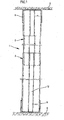
- a stand profile 1 that essentially consists of an inner profile 2 and a External profile 3 exists.
- the foot piece 4 of the outer profile 3 is in a U-rail 5 is used, which in turn on the ground. 6 a building is fixed while a head piece 7 of the Inner profile 2 is inserted at a further U-rail 8, the in turn fixed to a ceiling 9 of a building.
- the inner profile 2 and the outer profile 3 are in this embodiment made of metal, z. B. made of aluminum and the inner profile 2 is designed to be displaceable on the outer profile 3, so that depending on the height of the stand profile 1 to be used Inner profile 2 more or less pulled out of the outer profile 3 can be achieved until the required total height is.
- Fig. 2 illustrates the upright profile 1 with inserted inner profile is, from the connection profile 3, only the head piece. 7 the inner profile 2 is formed outstanding.
- Fig. 3 shows the upright profile 1 at partially pulled out Inner profile 2 is from this drawing as well as from Fig. 1 is clearly seen that the head 7 with respect to the further formed to the outer profile 3 directed inner profile 2 widened is.
- This broadening can z. B. by placing the widened Head piece 7 on the hull of the inner profile 2 done and by connecting these two elements.
- the head piece 7 has the same width as the outer profile 3, d. H. in an advantageous embodiment that has Headpiece 7 the same outer dimensions as the foot piece 4, for the attachment of both the foot piece 4 and the Headpiece 7
- Head piece 7 has the advantage that an undesired complete inward sliding of the inner profile 2 in the outer profile 3 is not possible is, but the head piece 7 on the front side of the outer profile 3 touches as shown in Fig. 2 can be seen.
- FIG. 5 is a cross section through the upright profile 1, wherein the inner profile 2 with his Outer clings to the inside of the outer profile 3.
- Both the inner profile 2 and the outer profile 3 are as C profile formed and have on the side walls 12, 14 as well as on the rear wall 10 profiling 15 to even with low wall thickness a desired stability of to reach entire stand profile 1.
- a spring 16 related to a piece of spring steel can be formed and under tension in the inner profile 2 is clipped, so that the spring force in the direction the direction shown by arrows, d. H . the spring 16 presses the inner profile 2 to the outer profile 3 and thus causes a clamping of the inner to the outer profile.
- This clamping effect is enough to the two profiles 2, 3 in the respectively desired Able to be with each other until z. B. plasterboard have been attached to the upright profile 1.
- any other suitable holding device be used to join the two profiles 2, 3 together to be noticed, such as B. screw, toggle connections, Clips o.
- the proposed spring 16 has however, the advantage that it is very easy to assemble, because it is sufficient to the already slightly preformed spring 16 with their one end in the inner profile 2 insert so that they on a horn 16 of the inner profile 2 is applied and then only needs the opposite end of the spring 16 in the Inner profile 2 are pressed in, so that it is on the opposite Horn rests.
- the spring 16 may, for. B. from a 1 cm wide and 0.5 mm thick spring steel piece exist.
- the proposed upright profile 1 also from more than two mutually displaceable profile elements consist of other telescopically designed Profile pieces.
Abstract
Description
Dies wird in einfacher Weise dadurch möglich, wenn das Außen-und das Innenprofil als C-Profil ausgebildet sind.
- Fig. 1
- ein Ständerprofil darstellt, das an Halteschienen an einem Bauwerk angeordnet ist,
- Fig. 2
- zeigt ein ineinander geschobenes Ständerprofil,
- Fig. 3
- zeigt ein auseinander gezogenes Ständerprofil,
- Fig. 4
- zeigt die Rückansicht eines Ständerprofils und
- Fig. 5
- stellt im Querschnitt ein Ständerprofil samt Feder dar.
Claims (11)
- Ständerprofil, insbesondere für den Trockenbau, gekennzeichnet durch das aus einem Außenprofil (3) und einem davon gehaltenen Innenprofil (2) ausgebildete Ständerprofil (1),
wobei das Außenprofil (3) und das Innenprofil (2) verschiebbar zueinander angeordnet sind, und
wobei das Außenprofil (3) die eine Endung und das Innenprofil (2) die andere Endung des Ständerprofils (1) ausbildet. - Ständerprofil gemäß Anspruch 1,
gekennzeichnet durch das Außenprofil (3), dass das Innenprofil (2) zumindest teilweise umgreifend ausgebildet ist. - Ständerprofil gemäß Anspruch 1 oder 2,
gekennzeichnet durch das als C-Profil ausgebildete Außenprofil (3) und Innenprofil (2). - Ständerprofil gemäß einem der vorherigen Ansprüche, gekennzeichnet durch das Innenprofil (2), das sich an die Innenwandungen des Außenprofils (3) anschmiegend ausgebildet ist.
- Ständerprofil gemäß einem der vorherigen Ansprüche, gekennzeichnet durch die Wandungen des Innenprofils (2) und des Außenprofils (3), die zumindest teilweise profiliert ausgebildet sind.
- Ständerprofil gemäß einem der vorherigen Ansprüche, gekennzeichnet durch mindestens eine lösbar ausgebildete auf das Ständerprofil (1) wirkende Haltevorrichtung zugunsten einer Fixierung des Außen- und Innenprofils in der gewünschten Lage zueinander.
- Ständerprofil gemäß Anspruch 6,
gekennzeichnet durch eine auf die Innenwandung des Innenprofils (2) wirkende Spreizvorrichtung als Haltevorrichtung. - Ständerprofil gemäß Anspruch 7,
gekennzeichnet durch eine Feder (16) als Spreizvorrichtung. - Ständerprofil gemäß einem der vorherigen Ansprüche, gekennzeichnet durch das Innenprofil (2), das an seiner einen Endung ein Kopfstück (7) aufweist, das gegenüber dem übrigen Innenprofil (2) verbreitert ausgebildet ist.
- Ständerprofil gemäß Anspruch 9,
gekennzeichnet durch das Kopfstück (7) des Innenprofils (2), das die gleichen Abmessungen eines Fußstückes (4) des Außenprofils (3) aufweist. - Ständerprofil gemäß einem der vorherigen Ansprüche, gekennzeichnet durch Bohrungen (11) in den Rückwandungen (10) des Ständerprofils (1).
Applications Claiming Priority (2)
| Application Number | Priority Date | Filing Date | Title |
|---|---|---|---|
| DE200420005703 DE202004005703U1 (de) | 2004-04-10 | 2004-04-10 | Ständerprofil |
| DE202004005703U | 2004-04-10 |
Publications (2)
| Publication Number | Publication Date |
|---|---|
| EP1584765A2 true EP1584765A2 (de) | 2005-10-12 |
| EP1584765A3 EP1584765A3 (de) | 2006-10-25 |
Family
ID=32892603
Family Applications (1)
| Application Number | Title | Priority Date | Filing Date |
|---|---|---|---|
| EP05007764A Withdrawn EP1584765A3 (de) | 2004-04-10 | 2005-04-08 | Ständerprofil |
Country Status (2)
| Country | Link |
|---|---|
| EP (1) | EP1584765A3 (de) |
| DE (1) | DE202004005703U1 (de) |
Cited By (2)
| Publication number | Priority date | Publication date | Assignee | Title |
|---|---|---|---|---|
| DE202010015260U1 (de) | 2010-11-10 | 2011-02-10 | Braun, Erwin | Längenverstellbares Ständerprofil für Leichtbauwände |
| FR3033604A1 (fr) * | 2015-03-09 | 2016-09-16 | Saint Gobain Isover | Systeme de deux profiles associes pour ossature |
Families Citing this family (1)
| Publication number | Priority date | Publication date | Assignee | Title |
|---|---|---|---|---|
| BE1026083B1 (nl) * | 2018-03-08 | 2019-10-10 | Junovation Bvba | Aanpasbaar profielsysteem |
Citations (4)
| Publication number | Priority date | Publication date | Assignee | Title |
|---|---|---|---|---|
| DE2123726A1 (de) * | 1971-05-13 | 1972-11-16 | Vasiljevic, Costa Silav, Dipl.-Ing. Dr., 7400 Tübingen | Schale, insbesondere für mehrschalige Trennwände |
| US4936067A (en) * | 1988-11-30 | 1990-06-26 | National Gypsum Company | Stud extender interlock and method of erection |
| WO1998015698A1 (en) * | 1996-10-07 | 1998-04-16 | 527233 B.C. Ltd. | Folding telescopic prefabricated framing units for non-load-bearing walls |
| DE19856542A1 (de) * | 1998-12-08 | 2000-06-15 | Zimmermann Norbert | Leichtbau-Trennwand und Bausatz zu ihrer Herstellung |
-
2004
- 2004-04-10 DE DE200420005703 patent/DE202004005703U1/de not_active Expired - Lifetime
-
2005
- 2005-04-08 EP EP05007764A patent/EP1584765A3/de not_active Withdrawn
Patent Citations (4)
| Publication number | Priority date | Publication date | Assignee | Title |
|---|---|---|---|---|
| DE2123726A1 (de) * | 1971-05-13 | 1972-11-16 | Vasiljevic, Costa Silav, Dipl.-Ing. Dr., 7400 Tübingen | Schale, insbesondere für mehrschalige Trennwände |
| US4936067A (en) * | 1988-11-30 | 1990-06-26 | National Gypsum Company | Stud extender interlock and method of erection |
| WO1998015698A1 (en) * | 1996-10-07 | 1998-04-16 | 527233 B.C. Ltd. | Folding telescopic prefabricated framing units for non-load-bearing walls |
| DE19856542A1 (de) * | 1998-12-08 | 2000-06-15 | Zimmermann Norbert | Leichtbau-Trennwand und Bausatz zu ihrer Herstellung |
Cited By (3)
| Publication number | Priority date | Publication date | Assignee | Title |
|---|---|---|---|---|
| DE202010015260U1 (de) | 2010-11-10 | 2011-02-10 | Braun, Erwin | Längenverstellbares Ständerprofil für Leichtbauwände |
| EP2453066A2 (de) | 2010-11-10 | 2012-05-16 | Erwin Braun | Längenverstellbares Ständerprofil für Leichtbauwände |
| FR3033604A1 (fr) * | 2015-03-09 | 2016-09-16 | Saint Gobain Isover | Systeme de deux profiles associes pour ossature |
Also Published As
| Publication number | Publication date |
|---|---|
| DE202004005703U1 (de) | 2004-08-19 |
| EP1584765A3 (de) | 2006-10-25 |
Similar Documents
| Publication | Publication Date | Title |
|---|---|---|
| DE2706437C2 (de) | Vorrichtung zum Verbinden von wenigstens zwei, vorzugsweise aus Hohlprofilen gebildeten Rahmenteilen mittels eines Verbindungselementes | |
| DE19941714A1 (de) | Haltevorrichtung in einem Kraftfahrzeug | |
| DE3702128C2 (de) | Halterung zur ausrichtbaren Befestigung der Pfosten eines Balkongeländers | |
| DE102008006917B4 (de) | Vorrichtung zur Lageverstellung eines Kabelkanals oder dergleichen | |
| DE102016012946A1 (de) | Vorrichtung zur Erleichterung der Anbringung von Hilfsmitteln zur Herstellung einer oberen Begrenzung einer Wandöffnung im Bauwesen | |
| EP1584765A2 (de) | Ständerprofil | |
| EP1655424B1 (de) | Verstellbare Richt- oder Abziehschiene | |
| DE2637749A1 (de) | Einbau-traggeruest fuer hohlkoerperwaende zur befestigung von wandhaengenden sanitaereinrichtungen | |
| DE202018103083U1 (de) | Befestigungssystem mit Kraftverteilung | |
| DE10200251B4 (de) | Schalungsbauteil und Sturzkasten | |
| DE19938970A1 (de) | Träger, insbesondere für den Messe- und Ladenbau | |
| DE202017102414U1 (de) | Rahmenkonstruktion für ein Regalsystem | |
| DE202004009557U1 (de) | System zur Aufhängung von Rohren, Leitungen o.dgl. an einer Decke | |
| EP0918127A1 (de) | Türfutter und Montagevorrichtung | |
| EP0468190A1 (de) | Trittleiter | |
| DE19612789C1 (de) | Vorrichtung zum Festlegen von Rohrleitungen | |
| DE202018100541U1 (de) | Verkleidungssystem zur Verkleidung einer Bauwerksfläche | |
| DE102018004030A1 (de) | Installationsblock | |
| DE3642846C2 (de) | ||
| EP2312085B1 (de) | Sichtschutzvorrichtung | |
| DE202008015022U1 (de) | Schlitzrinne mit Höhenverstellung | |
| DE2637846A1 (de) | An einem traggeruest befestigbare wandverkleidung | |
| DE7626246U1 (de) | Einbau-traggeruest fuer hohlkoerperwaende zur befestigung von wandhaengenden sanitaereinrichtungen | |
| DE3616838A1 (de) | Auf baustellen verwendbare vorrichtung zum anbringen von gelaenderbrettern od. dgl. | |
| EP3146123B1 (de) | Fugenabdeckvorrichtung |
Legal Events
| Date | Code | Title | Description |
|---|---|---|---|
| PUAI | Public reference made under article 153(3) epc to a published international application that has entered the european phase |
Free format text: ORIGINAL CODE: 0009012 |
|
| AK | Designated contracting states |
Kind code of ref document: A2 Designated state(s): AT BE BG CH CY CZ DE DK EE ES FI FR GB GR HU IE IS IT LI LT LU MC NL PL PT RO SE SI SK TR |
|
| AX | Request for extension of the european patent |
Extension state: AL BA HR LV MK YU |
|
| PUAL | Search report despatched |
Free format text: ORIGINAL CODE: 0009013 |
|
| AK | Designated contracting states |
Kind code of ref document: A3 Designated state(s): AT BE BG CH CY CZ DE DK EE ES FI FR GB GR HU IE IS IT LI LT LU MC NL PL PT RO SE SI SK TR |
|
| AX | Request for extension of the european patent |
Extension state: AL BA HR LV MK YU |
|
| AKX | Designation fees paid | ||
| STAA | Information on the status of an ep patent application or granted ep patent |
Free format text: STATUS: THE APPLICATION IS DEEMED TO BE WITHDRAWN |
|
| 18D | Application deemed to be withdrawn |
Effective date: 20070426 |
|
| REG | Reference to a national code |
Ref country code: DE Ref legal event code: 8566 |